

Systems
Technical
Publication
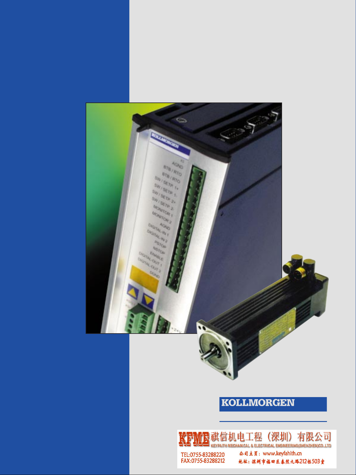
SERVOSTAR
®
600
with Kollmorgen GOLDLINE™
BH/MH Motors
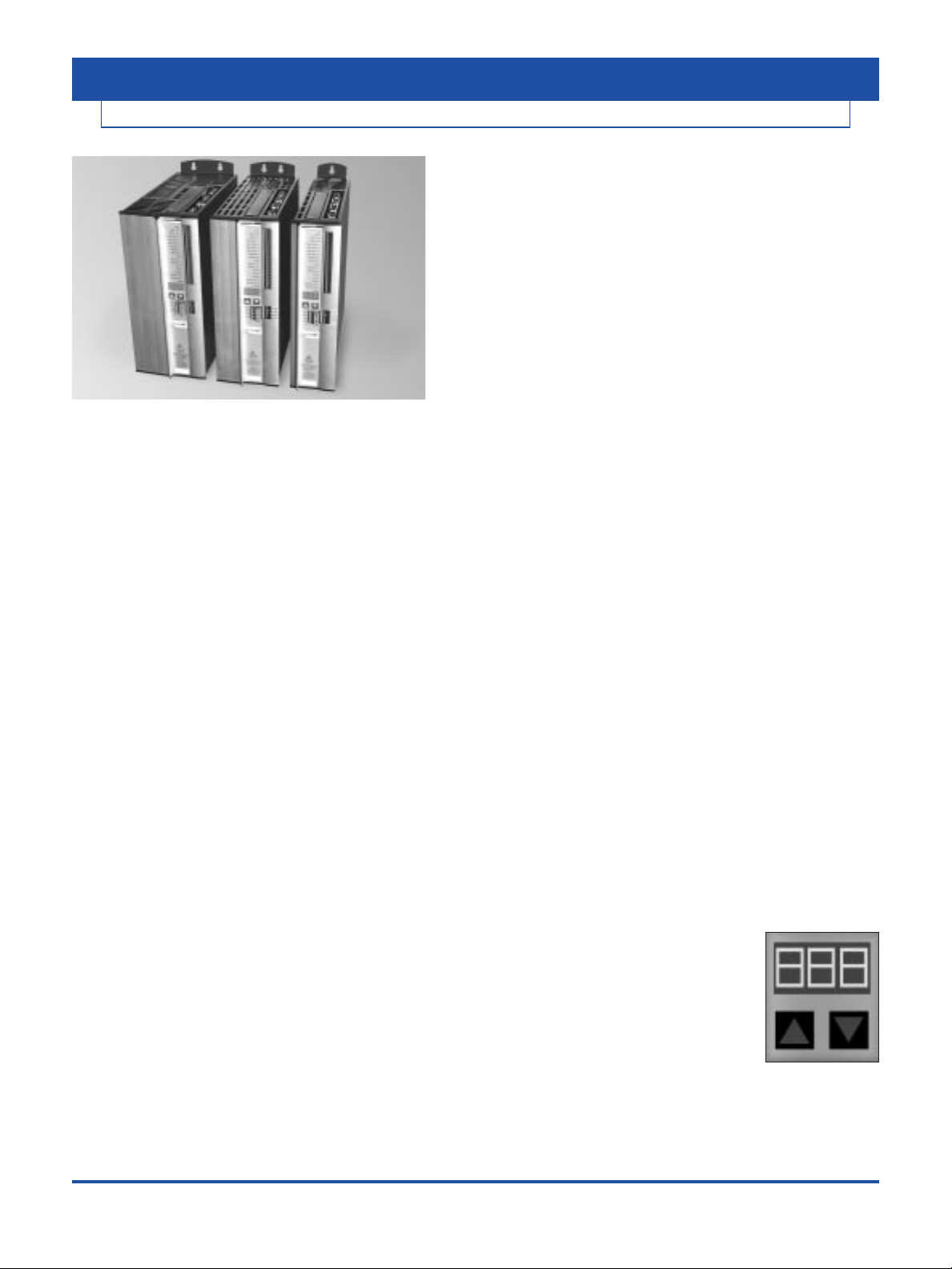
Kollmorgen SERVOST AR®600 Amplifier
• 400 to 480 Volt Three Phase
AC Input Power
• Resolver Feedback
• Integrated Power Supply
• Fully Digital Control
• CE, UL, cUL
The SERVOSTAR 600 amplifier is a compact, fully digital
drive-amplifier designed to simplify installation, system setup, and system reliability.
FEATURES:
Servo Control
• Easy to tune servo loops
• Advanced sinewave commutation technology
provides smooth, precise low-speed control and
high speed performance
• Velocity loop bandwidths to 400 Hz
• DQ Current control increases high speed peak torque
performance for faster cycle rates
• Space Vector Modulation reduces normal power stage
switching loses
• Torque angle control enhances motor performance
• Fully digital control loops
• Compact and attractive rugged metal package for spacesaving, modern appearance - metal package minimizes
electrical noise emmision & suceptability
• Command modes: Torque, Velocity, Position, Electronic
Gearing Pulse Following, and Motion Task
• Five current ratings: 3, 6, 10, 14, and 20 amp RMS/phase
continuous
• 2 to 1 peak/continuous current rating (5 second at peak)
• Run time counter
Easy Connectivity
• Built in encoder equivalent output can eliminate the need
for an additional position feedback device
• RS-232 Communication
• Unique multi-drop configuration allows a PC or PLC to
communicate to multiple SER VOSTAR600 amplifiers via
single RS-232 connection
• SERVOSTAR 600’s versatile communication capabilities
make it easy to integrate machine control data directly
from the factory floor to your information system
• Analog ±10V, pulse/direction, master encoder, and serial
port, I/O command options
Robust Design
• ESD rugged circuit design and fully metallic enclosure
• Full protection against short circuit, overvoltage,
undervoltage, heatsink overtemperature, motor overtemperature, overspeed, overcurrent, and feedback loss
• UL , cUL listed, and CE
• Built-in line filter for CE
• Flash memory
Windows Start-up Environment
• Graphical environment simplifies set up
• PC “Oscilloscope” for measuring real-time
motion performance
• Interactive MOTIONTASK Programming
Configurable I/O
• 2 separate analog inputs (14 and 12 bit resolution)
configurable to 6 different command modes
• 2 analog outputs
• 4 digital inputs
• 2 digital outputs
• I/O can be configured to a variety of functions to
customize the SERVOSTAR 600 to individual machines
I/O Option Card (see page 5)
• Adds 14 additional digital inputs and 8 digital outputs
• All I/O are optically isolated
• Simple plug in to top face of Amplifier
Regenerative Power Sharing
• Patented circuitry allows the DC bus from two or more
amplifiers to be connected together allowing regen power
to be shared among multiple drives
Built in Parameter Unit
• Perform basic drive set up without
the need for a PC
• Provides diagnostic information
• Allows motor selection from
parameters store in memory
Built in Safety Relay
• Switches off the power stage to ensure personnel safety
and prevents an unintended restart of the drive, even in
the event of a fault
• Allows DC bus to remain on
INTRODUCTION
SERVOSTAR®600
KOLLMORGEN
2
INCREMENT ALMOVE
ABSOLUTE MOVE
ELECTRONIC GEARING 5:1 (MASTER/SLAVE)
MACRO MOVE
• material handling
• bottle making
• packaging
• soft positioning
• robot
• conveyor belt controlling
• fast positioning
• special cleaning process
• part selection
• glass processing
• robot
• wirepuller
• textile industry
• printing
• electronics
• web converting
• cut to length
SERVOSTAR 600
KOLLMORGEN
INTRODUCTION
3
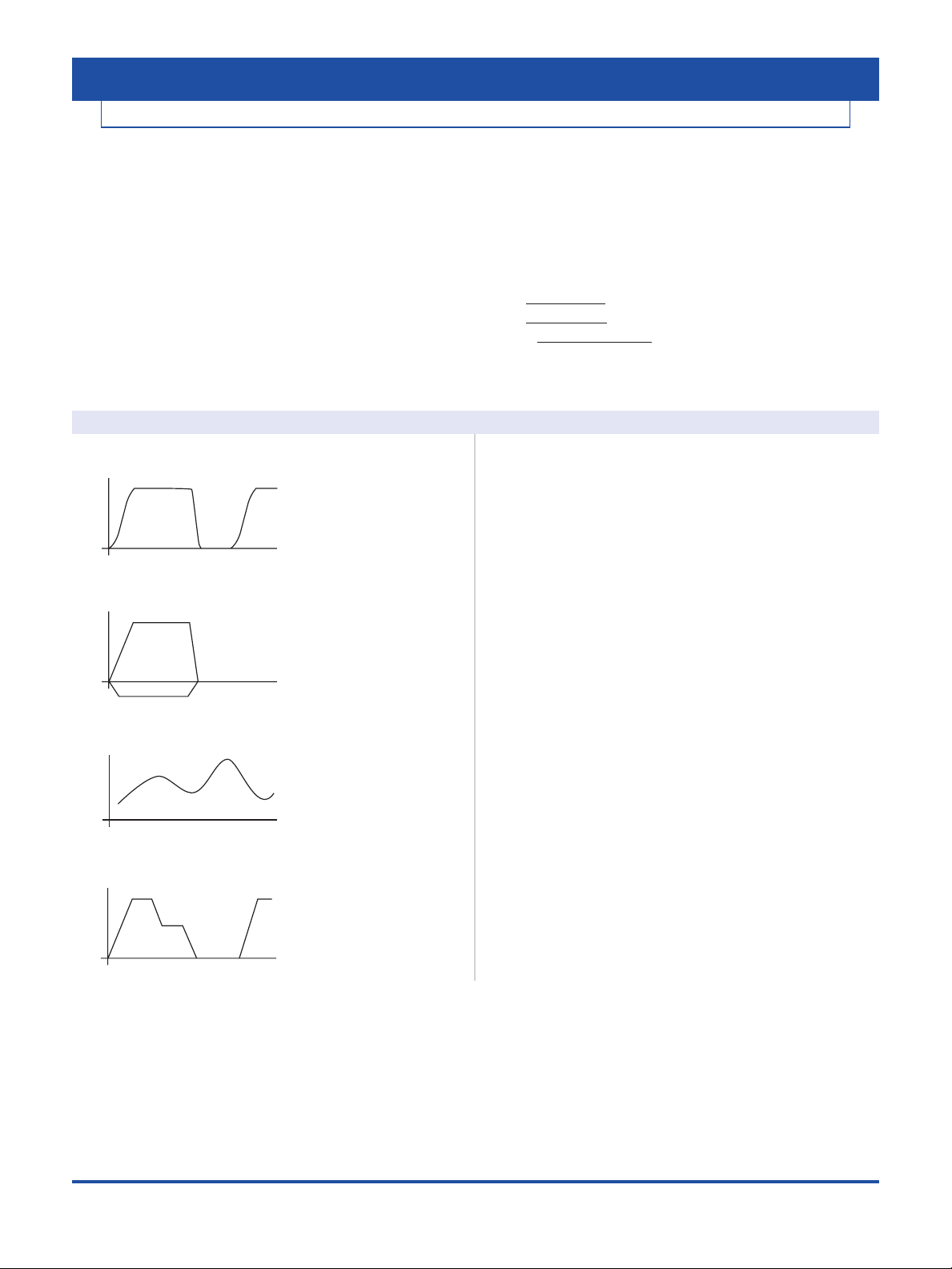
Motion Capabilities
The SER VOSTAR 600 can be configured to perform motion
control that normally requires a fully programmable drive
with a motion language. With the SERVOSTAR 600 there is
no programming language to learn; the user only “fill in the
blanks” to create common motion tasks
• Up to 180 motion task can be stored in
permanent memory
• Motion Tasked can be linked together.
• 10 types of homing
• Speed profile/registration control
• Adjustable S curve acceleration
• Absolute and relative (index) moves
• Linking of motion task (sequencing)
• Adjustable Following-Error window
• Adjustable window for the In Position signal
Linked motion tasks are started:
• Immediately upon reaching a targeted position
• Digital Input upon reaching the targeted position
• APreset Time Delayafter the targeted position is reached
Motion Examples Application Examples
Velocity
Time
Velocity
Position
Velocity
Time
Velocity
Time
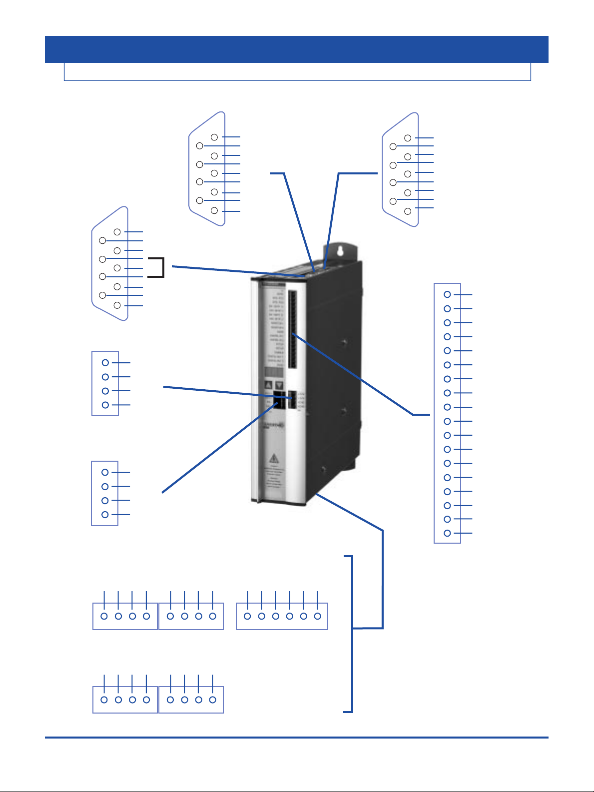
CONNECTOR INFORMATION
SERVOSTAR 600
AGND
BTB/RTO
BTB/RTO
SW/SETP.1+
SW/SETP.1SW/SETP.2+
SW/SETP.2MONITOR1
MONITOR2
AGND
DIGITAL-IN1
DIGITAL-IN2
PSTOP
NSTOP
ENABLE
DIGITAL-OUT1
DIGITAL-OUT2
DGND
1
2
3
4
X3 I/O
5
6
7
8
9
10
11
12
13
14
15
16
17
18
+24V 1
+24V 2
XGND 3
XGND 4
1
2
3
4
X4 24V INPUT
+8V
CANL
RxD
TxD
N.C.
CANH
PGND
X6 PC
1
6
2
7
3
8
4
9
5
PGND
B+ (DATA)
Motor +
B- (/DATA)
Motor +5V
A- (CLK)
N.C.
A+ (/CLK)
X5 Encoder Equivalent Output
1
6
2
7
3
8
4
9
5
R2
R1
S3
S1
S4
S2
THERMOSTAT
THERMOSTAT
SHIELD
X2 RESOLVER
5
9
4
8
3
7
2
6
1
L1
L2
L3
PE
-RB+R
Bint
R
BEXT
n.c.
1
2
3
4
XO
B
X8 R
REGEN
XO
A
X7 DC-circuit
Brake-
Brake+PEU2
V2
W2
1
2
3
4
5
6
X9 motor/brake
1
2
3
4
L1
L2
L3
PE
+DC
-DC
+DC
-DC
1
2
3
4
1
2
3
4
Connectors underneath:
KSO1 1
KSO2 2
KSI- 3
KSI+ 4
1
2
3
4
X10 MOTOR
DISCONNECT
RELAY
KOLLMORGEN
4
CONNECTOR POSITION
CONNECTOR ASSIGNMENTS
Connector Connector
X11A X11B
Terminal Fn. Description Terminal Fn. Description
1 In A0 1 In MT_Restart
2 In A1 2 In Start_MT
3 In A2 3 Out InPos
4 In A3 4 Out Next-InPos
5 In A4 5 Out Sfault
6 In A5 6 Out PosReg1
7 In A6 7 Out PosReg2
8 In A7 8 Out PosReg3
9 In Reference 9 Out PosReg4
10 In Sfault_clear 10 Out Reserve
11 In Start_MT Next 11 Sup. 24V DC
12 In Start_Jog v=x 12 Sup. I/O-GND
SERVOSTAR 600
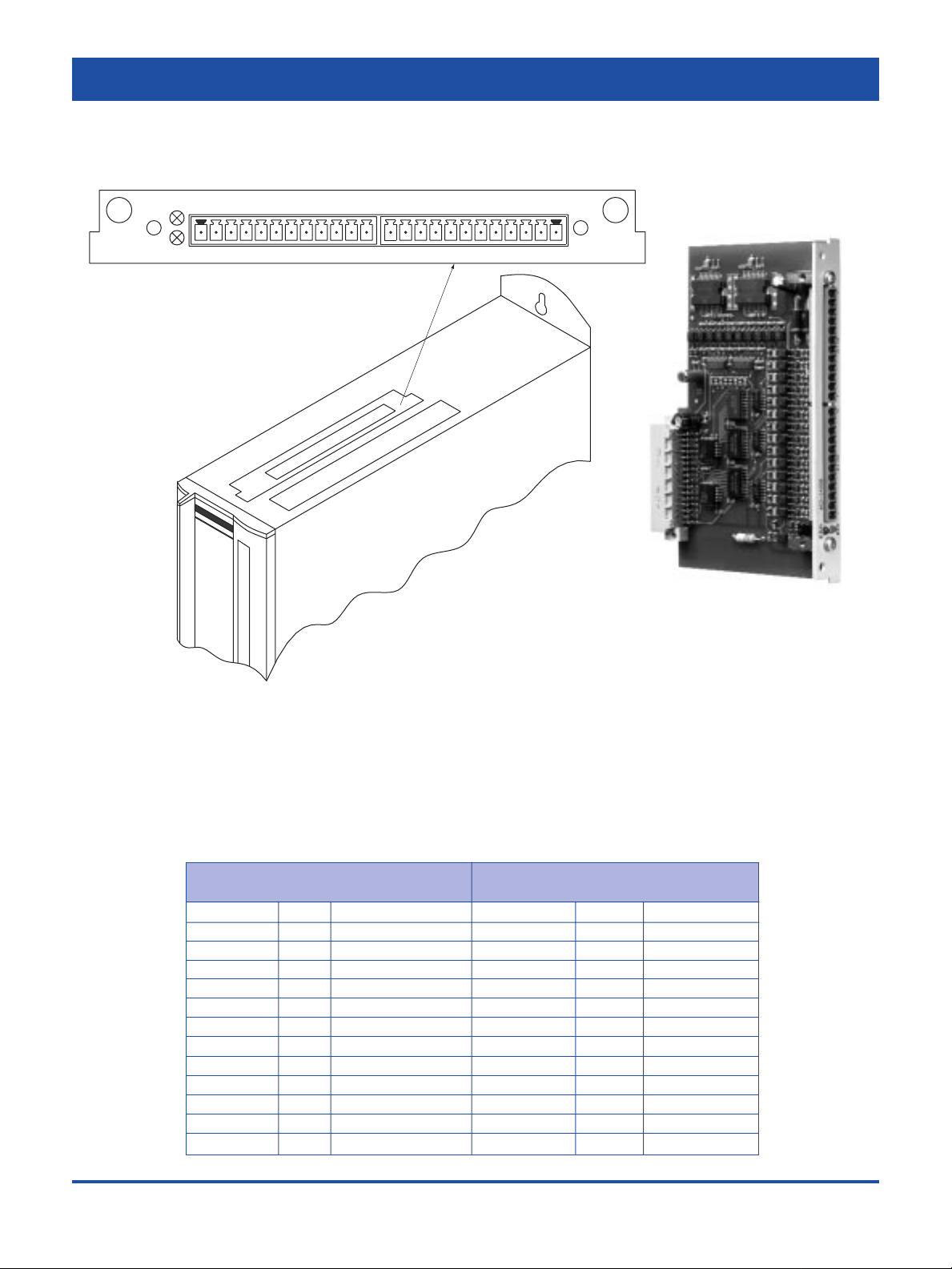
I/O OPTION CARD
ERR I/O-14/08 X11A
X11
X11B
12112124V
The I/O option card is an extremely economical way of operating
servo controllers under position control for simple automation tasks.
14 additional digital inputs permit the selection and start of the motion
tasks that are stored in the motion-task memory of the SERVOSTAR
®
600. All the important functions for the position controller that
is integrated into the servo controller can thus be operated from a
small, independent control system.
8 digital outputs report the status of the drive to the higher-level control.
KOLLMORGEN
5

AMPLIFIER SPECIFICATIONS
SERVOSTAR 600
Electrical characteristics
• Closed loop velocity bandwidth up to 400 Hz
• Motor current ripple frequency 16 kHz
• Switching frequency: 8 kHz
• Long term speed regulation (0.01%)
• Position loop update rate 250 µs (4 kHz)
• Velocity loop update rate 250 µs (4 kHz)
• Commutation update rate 62.5 µs (16 kHz)
• SVM Current loop update rate 62.5 µs (16 kHz)
Fault protection
• Output phase to phase and phase to ground short circuit protection
• Overvoltage
• Undervoltage
• Overtemperature (motor and amplifier)
• Overspeed
• Overcurrent
• Feedback loss
• Foldback
• Supply loss
• Excessive position error
Environmental
• Operation range
- Ambient 0 to 45°C (derated above ambient up to 55˚C)
- Storage -25°C to 55°C
• Humidity (non-condensing) max 85%
Velocity Loop Compensation
• PI Plus controller (PDFF Format) or PI controller
• Field tunable and digital repeatability
Position Loop Compensation
• Proportional loop with Feed Forward
Analog I/O
• 2 Configurable Inputs: ±10V, 12 and 14 bit resolution
• 2 Configurable Outputs: ±10V, 10 bit resolution
Digital I/O
• 4 Configurable Inputs: 24 volts, PLC-compatible
• 2 Configurable Outputs: 24 volts (open collector), PLC-compatible
• Remote enable Input: 24V, PLC-compatible
Drive Status Relay (BTB/RTO)
• Contact closure rated for 0.5 amps, 24 Volt
Pulse or Master/Slave Input
• Pulse command: pulse/direction or quadrature encoder format
• RS-485 receivers
• Up to 16 slave amplifiers can be connected together
• Input ratio is configurable
Position Feedback For User (Encoder Equivalent Output Port)
• Configurable to Encoder Equivalent (ROD) or SSI format
• Encoder Equivalent (ROD): A Quad B with Marker (zero) pulse,
RS-485 driver
• SSI (serial synchronous interface): max clock frequency is 1.5 Mhz,
RS-485 driver
• Programmable resolution
I/O Extension Card (Option)
• Field Installable
• 14 Digital Inputs 24V, PLC-compatible
• 8 Digital Outputs 24V, PLC-compatible
• 24V PLC Interface
Communications
• RS-232 Interface
Operational modes
• Torque control — from analog or digital command
• Velocity control — from analog or digital command
• Pulse following
• Gearing from quad encoder input
• Motion Task
• Serial Commands
Diagnostics
• 3 digit Seven segment LED display
• Error history log
• Internal variable monitoring
• PC scope
Motor Feedback
• Resolver
Motor Brake Control
• 24V optional holding brake in the motor can be controlled directly by
the SERVOSTAR 600
Power Inputs
• 400 to 480VAC 3phase, 50 or 60 Hz, built in line filter for
CE requirements
• 24 VDC @ 1 amp (3 amps with brake) For Logic
Power Regeneration Options
• Internal
• External - using BAR housed resistors
• Bus Sharing - Distributes regen power among multiple amplifiers
Built in Parameter Unit
• Displays drive status information
• Parameters: Drive Address, baud rate, Velocity loop tuning, Motor
type, Position output information format, brake, regen type
Model Output Continuous Output Peak Internal Power AC Input Rated Continuous Continuous
Current Per Phase Current Per Dissipation Line Input Internal External
(RMS/phase) Phase (Watts) Voltage Power (KVA) Regen Power Regen Power
(5 sec) (3 phase) @480 V (Watts) (Watts)
S603 3 6 40 400-480 2.3 80 500
S606 6 12 60 400-480 4.6 200 1,500
S610 10 20 90 400-480 8.1 200 1,500
S614 14 28 160 400-480 11.6 200 1,500
S620 20 40 200 400-480 16.6 200 1,500
Amplifier Ratings
KOLLMORGEN • keyfaith • 0755-83288220
6
DIMENSIONS/ORDERING INFORMATION
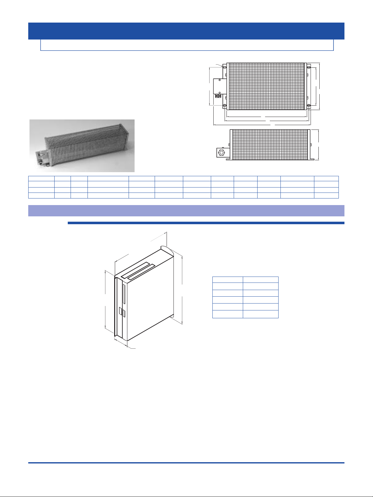
Resistive Regeneration Sizing
Shunt regeneration is required to dissipate energy that is pumped back
into the DC bus during load deceleration. The amount of shunt regeneration required is a function of the sum of simultaneously decelerating
loads. The loads need to be defined in terms of system inertia, maximum
speed, and deceleration time. In addition, the duty cycle must be known.
Application Note AS6000H details a calculation method to determine
proper regeneration sizing.
SERVOSTAR 600
SERVOSTAR 600 DIMENSIONS
S603/06/10
Dimensions in mm (inches)
Model Watts Ohms Amplifiers A B C D E1 E2 F G
BAR-250 250 33 S603, S606, S610 330(12.99) 390(15.35) 412(16.22) 66(2.60) 44(1.73) 35(1.38) 4,5x9(.20x.35) 77(3.03)
BAR-500 500 33 S603, S606, S610 400(15.75) 426(16.77) 486(19.13) 92(3.62) 64(2.52) 64(2.52) 6,5x9(.20x.35) 120(4.72)
BAR-1500 1500 33 S606, S610 500(19.69) 526(20.71) 586(23.07) 185(7.28) 150(5.91) 150(5.91) 6,5x9(.20x.35) 120(4.72)
DIM. “A”
3 AMP 70 (2.8)
6 AMP 70 (2.8)
10 AMP 70 (2.8)
14 AMP 100 (3.9)
20 AMP 120 (4.7)
KOLLMORGEN • keyfaith • 0755-83288220
7
F
E2
E1
D
A
B
C
G
265 (10.4)
with connector:
273 (10.7)
275
(10.8)
"A"
325
(12.8)
ADDITIONAL FUNCTIONS
KOLLMORGEN • keyfaith • 0755-83288220
8
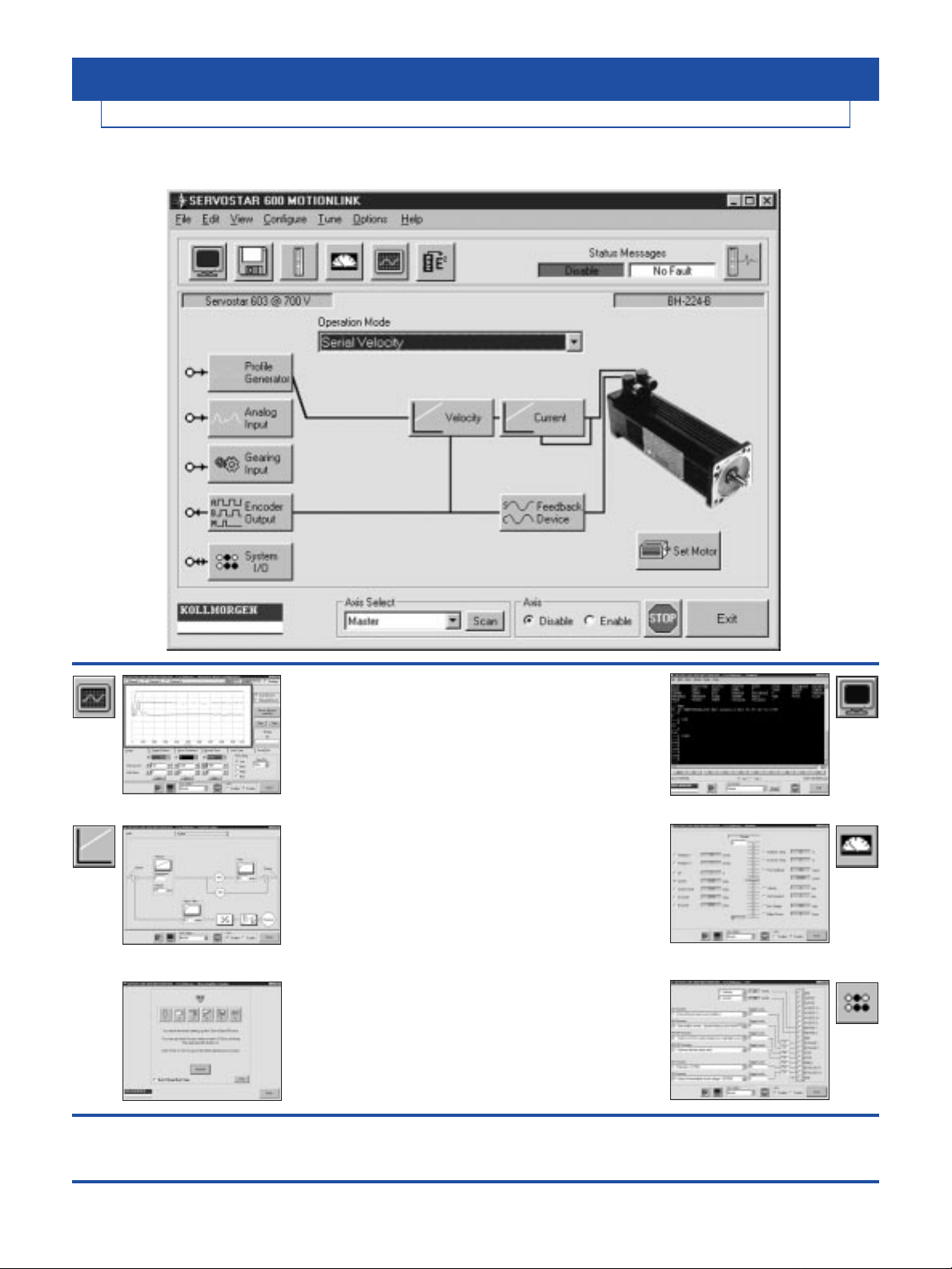
MOTIONLINK SERVOSTAR 600
PC Oscilloscope:
For closely evaluating system
performance MOTIONLINK includes
the functionality of an oscilloscope.
Y ou can very easily excite the load then
review performance graphically on
your computer screen.
Tuning:
Velocity and position loop tuning is
straight forward, allowing the novice user
to achieve the best machine performance.
Auto Set-up:
MOTIONLINK auto set-up environment
walks even the first time user through line
voltage, motor, operation mode and load
tuning to make system configuration
friendly and fast.
Direct Terminal Mode:
This mode turns your computer into a
“dumb terminal.” Variables or parameters
can be monitored and changed using
the SERVOSTAR
600’s
command
language. This mode is ideal for
advanced users who want to get directly
in the “heart” of the SERVOSTAR
600
.
Monitor Mode:
Allows you to monitor key operation
variables. Speed, torque, and other
variables can be viewed in real
PSEUDO time in linear gauge format.
Configuring I/O:
Inputs & Outputs are configurable to a
wide variety of functions to configure
the
SERVOSTAR 600
to individual
machine needs.
MOTIONLINK®for Windows takes the fear out of setting up a servo system. Designed for the novice as well as
the advanced user, MOTIONLINK lets users quickly set-up and fine tune system performance.
MOTIONLINK has many other features including: • Saving drive configuration to disk
• Activating position limits
• Displaying amplifier status
• Setting acceleration amps
• Limiting max speed or torque

KOLLMORGEN • keyfaith • 0755-83288220
9
CONFIGURABLE AND READABLE FUNCTIONS
Basic Set Up
• Input Power
• Main Phase Missing
• Max Regen Power
• Internal or External Regen Resistor
• Drive Name and Serial No *
• Run Time *
• Firmware Version *
• Hardware Version *
Drive Operation Modes
• Digital Speed
• Analog Speed
• Digital Torque
• Analog Torque
• Electronic Gearing
• External Position Control
• Internal Position - MotionTasks
Digital Scope Tool
• Record real time data
• Display on PC Oscilloscope
• Start Current Move
• Start Jog Move
• Start Position Move
• Record Start
• Adjust Trigger
• Recording in Process *
• Cancel Recording
• Recording Done *
• Transmit Data to PC Oscilloscope
Feedback Configuration
Resolvers:
• Number of Poles
• Resolver-zero offsetting
• Resolver Bandwidth
• Feedback Gain
Drive Monitoring
• Regen Wattage *
• Actual Position (within one rev) *
• Actual Position *
• Actual Speed *
• Command Speed *
• Current Foldback Level *
• Drive Temperature *
• Heatsink Temperature *
• Effective Current *
• D Current Component *
• Q Current Component *
• Analog Commands *
• DC Bus voltage *
MOTIONLINK
Velocity Control
• Speed Command Scaling
• Speed Command Ramp (Accel)
• Speed Command Ramp (Decel)
• Maximum Speed
• Proportional Gain
• Integral Time Constant
• Feedback Filter
• Motion direction
Current Control
• Current Command Scaling
• Current Foldback
• Cont Drive Current
• Peak Drive Current
• Proportional Gain
• Integral Time Constant
Motor Configuration
• Motor Name and Number *
• Motor Continuous Current
• Motor Peak Current
• Motor Inductance
• Motor Poles
• Motor Max Speed
• Motor Brake (with or without)
• Motor Adaptive Gain
• Motor Speed Angle Advance
• Motor Torque Angle Advance
Drive Status
• Actual Error *
• Actual Warning *
• Last 10 Errors *
• Rate of Occurrence *
• Drive Reset Command
Others
• Stop Drive
• Drive Enable
• Drive Disable
* READ ONLY
Motion Homing/Jogging
• Direction
• Homing Type
• Reference Offset
• Start Command
• Jog Command
• Homing Velocity
• Jog Velocity
Communications
• RS-232 from PC
• Drive Address
• Message Types from Drive
• Prompt Configuration
• Scan
Position Output (Motor)
• Format: Off, Encoder equivalent
output or SSI format
Encoder Equivalent Output
• Resolution of Encoder Equiv Output
• Marker Pulse Offset
SSI
• Baud rate of SSI Output
• Format type (binary or gray code)
• Standard or Inverted Clock
• Input Edge Positive or Negative
Position Control
• Proportional Gain
• Integral Action Time
• Feed Forward
• Following Error *
Motion-Gear Mode
• GearMode Type:
• Encoder Follower
• Pulse Follower
Mode 0
The amplifier uses Input 1 only, depending
on the operation mode.
Mode 1
The amplifier uses Input 1 or 2, depending
on the operation mode.
Mode 2
Both inputs are switched off.
Mode 3
The amplifier uses Input 1, depending on
the operation mode. Input 2 is used for limiting peak current.
Mode 4
The amplifier uses the sum of Inputs 1 and
2, depending on the setting of OPMODE.
Mode 5
The amplifier uses the product of Inputs 1
and 2, depending on the setting of
OPMODE. The voltage on Input 2 has the
effect of a weighting factor for Input 1.
OPMODE Input 1 Input 2
analog speed speed command inactive
analog torque torque command inactive
CONFIGURABLE AND READABLE FUNCTIONS
KOLLMORGEN • keyfaith • 0755-83288220
10
MOTIONLINK
• Change/Copy Motion Task
• Position Type (Rotary or Linear)
• Master/Slave
• Motion Task Stop
• In Position
• Set Position Registers
• Motion Task Start
• Acceleration ramp
• Deceleration Ramp
• Min Acceleration
• Max Velocity
• Position Capture (Positive or Negative Edge)
Motion Task (or Blocks)
OPMODE Input 1 + Input 2
analog speed speed setpoint
analog torque torque setpoint
OPMODE Input 1 Input 2
analog speed speed command inactive
analog torque inactive torque command
• Two Differential Analog Inputs that can be configured in the following ways:
Analog Input
OPMODE Input 1 Input 2
analog speed inactive inactive
analog torque inactive inactive
OPMODE Input 1 Input 2
analog speed speed command limits peak torque
analog torque torque command limits peak torque
OPMODE Input 1 • Input 2
analog speed speed setpoint
analog torque torque setpoint
Analog Output
• Two Analog Outputs can be configured for Actual Speed,
Actual Current, Commanded Speed, Commanded Current, or Contouring error window
• Signal dead band
• Signal offset
• Auto Offset command
• Input Configuration

MOTIONLINK
CONFIGURABLE AND READABLE FUNCTIONS
KOLLMORGEN • keyfaith • 0755-83288220
11
Digital I/O
Inputs:
The 4 digital inputs can be configured as follows:
IN1MODE=1 External drive reset (only available at Input 1)
IN3MODE=2 Activates PSTOP in positive direction of travel (only available at Input 3)
IN4MODE=3 Activates NSTOP in negative direction of travel(only available at Input 4)
IN3MODE=4 Activates PSTOP function combined with integral gain off (only available at Input 3)
IN4MODE=5 Activates NSTOP function combined with integral gain off (only available at Input 4)
IN3MODE=6 Activates both PSTOP and NSTOP (only available at Input 3)
IN3MODE=7 Activates both PSTOP and NSTOP with integral gain off (only available at Input 3)
INxMODE=8 Switch between analog input 1 and analog input 2
INxMODE=9 Select a motion task that is stored in memory
INxMODE=10 Turn integral gain off in the velocity loop
INxMODE=11 Switch between velocity and torque control
INxMODE=12 Home switch
INxMODE=13 Change over position feedback from encoder equivalent output format (ROD) to SSI format
INxMODE=14 Reset following error or limit infringement warning
INxMODE=15 Start next motion task once the targeted position is reached
INxMODE=16 Start a motion task. Enter task number through an auxiliary variable
INxMODE=17 Start motion task that is bit coded on the digital inputs
INxMODE=18 Switch over to second (lower) peak value of current
INxMODE=19 Reserved
INxMODE=20 Start jog. Enter speed through an auxiliary variable
INxMODE=21 Turn off undervoltage monitoring
INxMODE=22 Restart motion task that was interrupted
INxMODE=23 Same as INxMode 16 except motion task started on rising edge only
INxMODE=24 Switch between Opmodes a (Input high) and b (Input low) when INxTRIG = a*256+b
INxMODE=25 During set up, set encoder equivalent output marker pulse offset
IN2MODE=26 Position latch on rising edge of input (only available at Input 2)
INxMODE=30 On rising edge of input the string stored in INHCMD will be processed.
On falling edge of input the string stored in INLCMD will be processed. Multiple commands
in the string are possible up to total of 64 characters.
Outputs:
The 2 digital outputs can be configured as follows:
OxMODE=1 Motor speed is less than preset value
OxMODE=2 Motor seed is greater than preset value
OxMODE=3 Drive power stage ready
OxMODE=4 Preset regen power is exceeded
OxMODE=5 Software travel limit is reached
OxMODE=6 Actual position is greater than preset value
OxMODE=7 Target position reached (In Position)
OxMODE=8 Actual current feedback less than
preset value
OxMODE=9 Actual current feedback greater than
preset value
OxMODE=10 Following error exceeded
OxMODE=11 I2T monitoring threshold is reached
OxMODE=12 Preset function of position register
1 is reached
OxMODE=13 Preset function of position register
2 is reached
OxMODE=14 Preset function of position register
3 is reached
OxMODE=15 Preset function of position register
4 is reached
OxMODE=16 Target position reached for each task
in an automatically executed sequence of
motion task (Next-In Position)
OxMODE=17 Error or warning message is signaled
OxMODE=18 Error message is signaled
OxMODE=19 DC bus voltage is higher than an
auxiliary value
OxMODE=20 DC bus voltage is lower than an
auxiliary value
OxMODE=21 Drive is enabled
OxMODE=22 Marker pulse (low speeds only)
OxMODE=23 Option card status
OxMODE=24 Homing complete
OxMODE=28 Preset function of position register
0 is reached
OxMODE=29 Preset function of position register
5 is reached
OxMODE=35 Status of hardware and software enable
12
KOLLMORGEN • keyfaith • 0755-83288220
INTRODUCTION
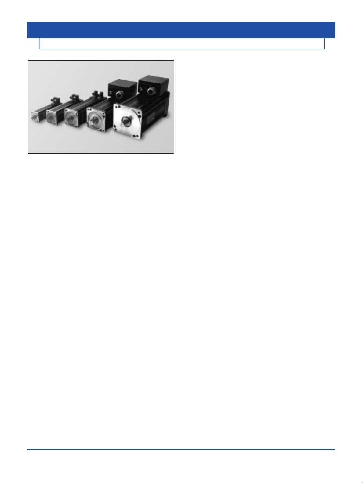
Kollmorgen GOLDLINE BH/MH
Kollmorgen GOLDLINE™ BH/MH Series
• 0.52 to 69 lb-ft (0.7 to 93 N-m)
• 70.0 to 190 mm (2.76 to 7.5 inches) Square Frame
• Resolver Feedback
• Speeds up to 7500 RPM
• 400/480 VAC, 565/680 VDC bus rated
Kollmorgen GOLDLINE BH/MH servomotors build on
the tradition of high performance motors from Kollmorgen.
Designed around the classic industry-standard Kollmorgen
GOLDLINE series, the BH/MH motors incorporate the
highest energy rare earth neodymium-iron-boron magnets
and excellent thermal design to provide exceptional
continuous torque and peak torque performance in a
compact package.
The servomotors incorporate the patented IPM (Interior
Permanent Magnet) design technology which results in
superior torque to inertia and torque per volume ratios.
The BH/MH line of servomotors is available in 5 frame
sizes and 3 stack lengths per frame. With multiple
windings per stack, the BH/MH series meet the needs of a
wide range of applications.
BH-Series (low inertia)
The BH-Series provides extremely low inertia rotors
allowing optimum performance in applications requiring
rapid acceleration and deceleration. The IPM magnetic
design provides for very high torque density and
torque/inertia ratios. When used with the SERVOSTAR
®
600 family of amplifiers, the resulting speed/torque is the
widest range in the industry.
MH-Series (medium inertia)
The MH-Series is an extension of the BH-Series. With
seven times higher inertia, this motor series offers the
advantage of better performance for systems having
compliant loads or larger inertia mismatches.
FEATURES: BH or MH Series
• Compact (high torque/volume ratio)
• Speeds to 7500 RPM standard
• IPM (Interior Permanent Magnet) design for low cogging
• CE Compliant, UL recognition
• Rugged resolver feedback
• Built-in thermostat
• Rear shaft extension for mounting additional feedback
devices
• Class H insulation system
• Rotatable CE connectors standard on 12x, 22x, 42x
• Terminal Box standard on 62x and 82x frames
OPTIONS:
• IP65 and IP67 sealing
• Fail-safe brake, 24 and 90VDC
• NEMA and Metric mountings
• Standard SERVOSTAR 600 UL/CE cable assemblies
available in 3 meter increments
MOTOR RATINGS
The motors performance capacity depends on the ability to
get rid of the heat generated within the motor package. The
ratings on the following pages assume that the motor is
mounted to a metal mounting bracket capable of drawing
heat energy away. The ratings assume the following:
a.) For BH12x and BH22x: Continuous Duty Ratings are
for a motor mounted to a 1/4 inch thick aluminum
faceplate of 96 square inches.
b.) For the BH42x, BH62x, and BH82x: Continuous Duty
Ratings are for a motor mounted to a 1 inch thick
aluminum faceplate plate of 452 square inches.
c.) Ambient temperature is 40° C (or less)
Equivalent thermal masses and radiating surface areas
are a common part of classical machine design. Other
applications require derating.
13
KOLLMORGEN • keyfaith • 0755-83288220
n
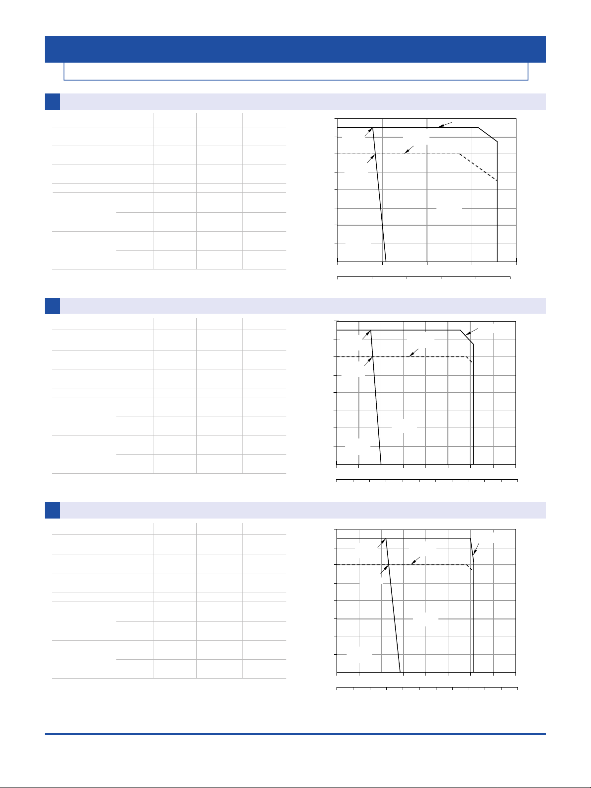
Motor BH-122-A or MH-123-AnAmplifier: S603
Performance Specification Symbol Units
Cont. Torque at stall Tc lb-ft 0.52
N-m 0.70
Peak Torque at stall Tp lb-ft 1.77
N-m 2.40
Cont. Power @480V
HP rated
HP 0.54
kW rated
kW 0.41
Max. Speed N RPM 7500
Motor Inertia BH Series Jm lb-ft-s
2
0.0000228
kg-m
2
0.000031
MH Series lb-ft-s
2
0.000156
kg-m
2
0.000212
Motor Weight BH Series Wt lb 5.5
kg 2.5
MH Series lb 7.0
kg 3.2
SYSTEM PERFORMANCE CURVES
Kollmorgen GOLDLINE BH/MH and SERVOSTAR 600
0
0 0.5 1.0 1.5 2.0 2.5
1.0 2.00.5 1.5
0
1000
2000
3000
4000
5000
6000
7000
8000
TORQUE
SPEED (RPM)
N-m
lb-ft
480V Limit
Intermittent
Duty Zone
400V Limit
(6,000 rpm)
0.41 kW
(0.54 HP)
Continuous
Duty Zone
0.4 kW
(0.5 HP)
0
0 0.5 1.0 1.5 2.0 2.5 3.0 3.5 4.0
1.0 2.0 3.00.5 1.5 2.5 3.5 4.0
0
1000
2000
3000
4000
5000
6000
7000
8000
TORQUE
SPEED (RPM)
4.5 5.0 5.5
lb-ft
N-m
480V Limit
Intermittent
Duty Zone
Continuous
Duty Zone
0.83 kW
(1.11 HP)
0.7 kW
(0.9 HP)
400V Limit
(6,000 rpm)
0
0 0.5 1.0 1.5 2.0 2.5 3.0 3.5 4.0
1.0 2.0 3.00.5 1.5 2.5 3.5 4.0
0
1000
2000
3000
4000
5000
6000
7000
8000
TORQUE
SPEED (RPM)
4.5 5.0 5.5
lb-ft
N-m
480V Limit
Intermittent
Duty Zone
Continuous
Duty Zone
400V Limit
(6,000 rpm)
1.2 kW
(1.6 HP)
1.0 kW
(1.3 HP)
1
2
3
n
Motor BH-124-B or MH-125-B nAmplifier: S603
Performance Specification Symbol Units
Cont. Torque at stall Tc lb-ft 1.00
N-m 1.35
Peak Torque at stall Tp lb-ft 3.10
N-m 4.20
Cont. Power @480V
HP rated
HP 1.11
kW rated
kW 0.83
Max. Speed N RPM 7500
Motor Inertia BH Series Jm lb-ft-s
2
0.0000340
kg-m
2
0.0000461
MH Series lb-ft-s
2
0.000249
kg-m
2
0.000338
Motor Weight BH Series Wt lb 7.0
kg 3.2
MH Series lb 9.0
kg 4.1
n
Motor BH-126-B or MH-127-B nAmplifier: S603
Performance Specification Symbol Units
Cont. Torque at stall Tc lb-ft 1.40
N-m 1.90
Peak Torque at stall Tp lb-ft 3.10
N-m 4.20
Cont. Power @480V
HP rated
HP 1.6
kW rated
kW 1.2
Max. Speed N RPM 7500
Motor Inertia B Series Jm lb-ft-s
2
0.0000564
kg-m
2
0.0000765
M Series lb-ft-s
2
0.00040
kg-m
2
0.00054
Motor Weight B Series Wt lb 8.5
kg 3.9
M Series lb 11.0
kg 5.0
• All curves shown at 60 Hz input, derate max. speed and peak power by 15% for 50 Hz operation.

14
KOLLMORGEN • keyfaith • 0755-83288220
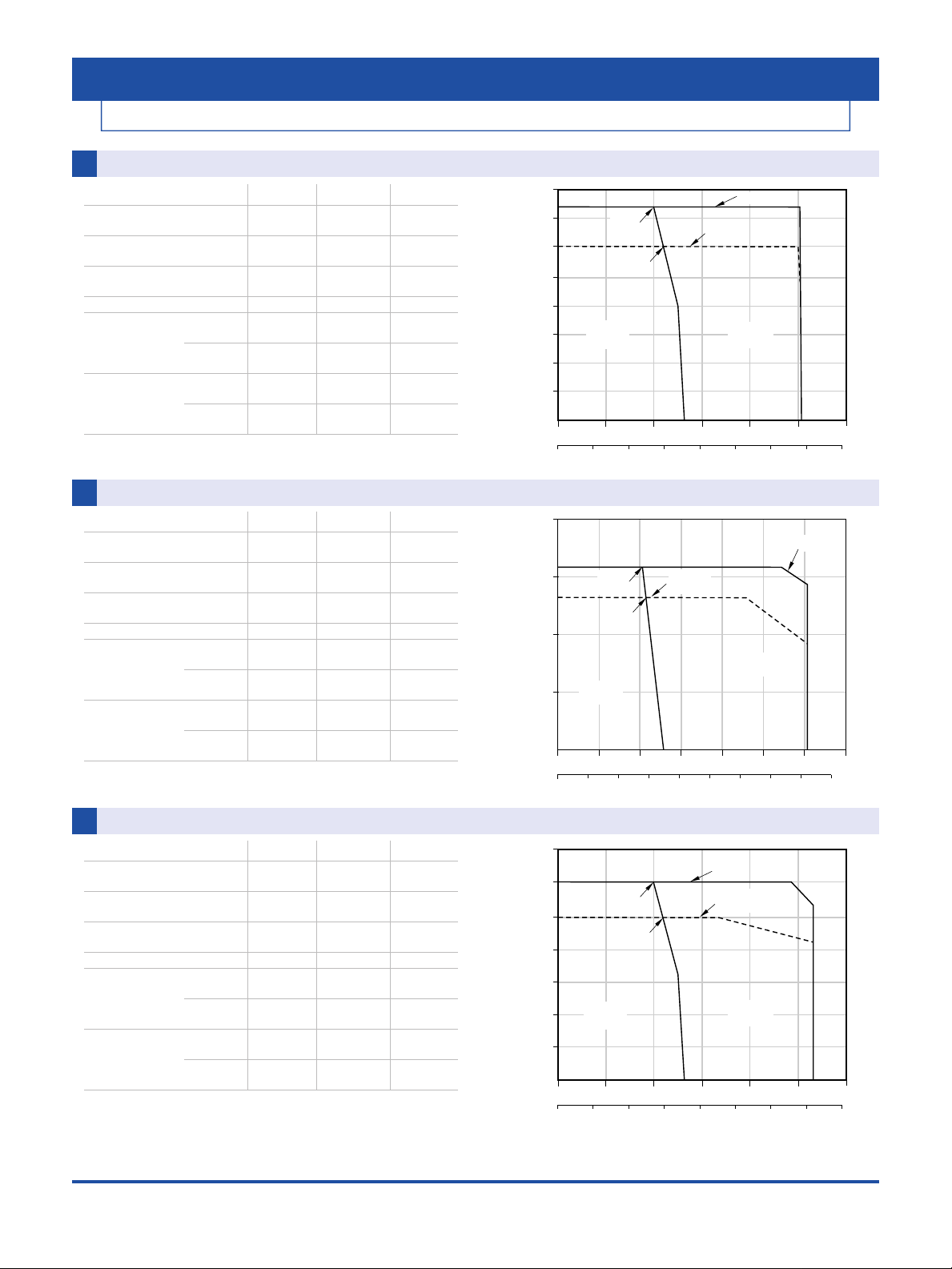
n
Motor BH-222-E or MH-223-E nAmplifier: S603
Performance Specification Symbol Units
Cont. Torque at stall Tc lb-ft 1.5
N-m 2.1
Peak Torque at stall Tp lb-ft 3.5
N-m 4.8
Cont. Power @480V
HP rated
HP 1.9
kW rated
kW 1.4
Max. Speed N RPM 7000
Motor Inertia BH Series Jm lb-ft-s
2
0.0000735
kg-m
2
0.0000996
MH Series lb-ft-s
2
0.000617
kg-m
2
0.000836
Motor Weight BH Series Wt lb 9.0
kg 4.1
MH Series lb 11.0
kg 5.0
SYSTEM PERFORMANCE CURVES
1000
2000
3000
5000
6000
7000
8000
4000
0
TORQUE
SPEED (RPM)
Continuous
Duty Zone
Intermittent
Duty Zone
480V Limit
0
0 1.0 2.0 3.0 4.0 5.0 6.0
2.0 4.01.0 3.0
lb-ft
N-m
1.4 kW
(1.9 HP)
1.1 kW
(1.5 HP)
400V Limit
(5,300 rpm)
1000
2000
3000
4000
5000
0
TORQUE
SPEED (RPM)
Continuous
Duty Zone
Intermittent
Duty Zone
0
0 1.0 2.0 3.0 4.0 5.0 6.0 7.0 8.0 9.0
2.0 4.0 6.01.0 3.0 5.0
lb-ft
N-m
1.6 kW
(2.1 HP)
1.3 kW
(1.7 HP)
400V Limit
(3,600 rpm)
480V Limit
4
5
n
Motor BH-226-C or MH-227-C nAmplifier: S606
Performance Specification Symbol Units
Cont. Torque at stall Tc lb-ft 4.1
N-m 5.6
Peak Torque at stall Tp lb-ft 10.5
N-m 14.2
Cont. Power @480V
HP rated
HP 2.9
kW rated
kW 2.2
Max. Speed N RPM 4900
Motor Inertia BH Series Jm lb-ft-s
2
0.0001853
kg-m
2
0.0002512
MH Series lb-ft-s
2
0.0013
kg-m
2
0.0018
Motor Weight BH Series Wt lb 16.7
kg 7.6
MH Series lb 21.0
kg 9.5
• All curves shown at 60 Hz input, derate max. speed and peak power by 15% for 50 Hz operation.
6
Kollmorgen GOLDLINE BH/MH and SERVOSTAR 600
n
Motor BH-224-G or MH-225-G nAmplifier: S603
Performance Specification Symbol Units
Cont. Torque at stall Tc lb-ft 2.8
N-m 3.8
Peak Torque at stall Tp lb-ft 5.4
N-m 7.3
Cont. Power @480V
HP rated
HP 2.1
kW rated
kW 1.6
Max. Speed N RPM 4600
Motor Inertia BH Series Jm lb-ft-s
2
0.0001275
kg-m
2
0.0001729
MH Series lb-ft-s
2
0.000843
kg-m
2
0.001143
Motor Weight BH Series Wt lb 13.6
kg 6.2
MH Series lb 16.0
kg 7.3
5000
4500
4000
3500
3000
2500
SPEED (RPM)
2000
1500
1000
500
0
TORQUE
2.2 kW
(2.9 HP)
1.9 kW
(2.5 HP)
Continuous
Duty Zone
0
0 1.0 2.0 3.0 4.0 5.0 6.0 7.0 8.0 9.0
2.0 4.0 6.0 8.0 9.0 10.0 11.01.0 3.0 5.0 7.0
400V Limit
(4,000 rpm)
Intermittent
Duty Zone
480V Limit
10.0 11.0 12.0 13.0 14.0 15.0
lb-ft
N-m

15
KOLLMORGEN • keyfaith • 0755-83288220
SYSTEM PERFORMANCE CURVES
Kollmorgen GOLDLINE BH/MH and SERVOSTAR 600
n
Motor BH-226-E or MH-227-E nAmplifier: S603
Performance Specification Symbol Units
Cont. Torque at stall Tc lb-ft 4.1
N-m 5.6
Peak Torque at stall Tp lb-ft 7.7
N-m 10.5
Cont. Power @480V
HP rated
HP 2.2
kW rated
kW 1.7
Max. Speed N RPM 3200
Motor Inertia BH Series Jm lb-ft-s
2
0.0001853
kg-m
2
0.0002512
MH Series lb-ft-s
2
0.0013
kg-m
2
0.0018
Motor Weight BH Series Wt lb 16.7
kg 7.6
MH Series lb 21.0
kg 9.5
7
9
n
Motor BH-424-D or MH-425-D nAmplifier: S606
Performance Specification Symbol Units
Cont. Torque at stall Tc lb-ft 7.8
N-m 10.6
Peak Torque at stall Tp lb-ft 14.7
N-m 20.0
Cont. Power @480V
HP rated
HP 4.4
kW rated
kW 3.3
Max. Speed N RPM 3700
Motor Inertia BH Series Jm lb-ft-s
2
0.000484
kg-m
2
0.000656
MH Series lb-ft-s
2
0.00325
kg-m
2
0.00441
Motor Weight BH Series Wt lb 27.5
kg 12.5
MH Series lb 34
kg 15.5
• All curves shown at 60 Hz input, derate max. speed and peak power by 15% for 50 Hz operation.
8
n
Motor BH-422-D or MH-423-D nAmplifier: S606
Performance Specification Symbol Units
Cont. Torque at stall Tc lb-ft 4.3
N-m 5.8
Peak Torque at stall Tp lb-ft 12.2
N-m 16.5
Cont. Power @480V
HP rated
HP 2.8
kW rated
kW 2.1
Max. Speed N RPM 4600
Motor Inertia BH Series Jm lb-ft-s
2
0.000238
kg-m
2
0.000323
MH Series lb-ft-s
2
0.00191
kg-m
2
0.00259
Motor Weight BH Series Wt lb 18.5
kg 8.4
MH Series lb 23.0
kg 10.5
1000
2000
3000
500
1500
2500
3500
4000
4500
5000
0
TORQUE
SPEED (RPM)
Continuous
Duty Zone
Intermittent
Duty Zone
0
0 2.0 4.0 6.0 8.0
2.0 4.0 6.0 8.0 9.0 10.0 11.0 12.0 13.01.0 3.0 5.0 7.0
10.0 12.0 14.0 16.0 18.0
lb-ft
N-m
2.1 kW
(2.8 HP)
1.7 kW
(2.3 HP)
400V Limit
(3,600 rpm)
480V Limit
4000
3500
3000
2500
2000
SPEED (RPM)
1500
1000
500
TORQUE
Continuous
Duty Zone
0
0
0 1.0 2.0 3.0 4.0 5.0 6.0 7.0 8.0 9.0
1.7 kW
(2.2 HP)
1.3 kW
(1.8 HP)
2.0 4.0 6.0 8.01.0 3.0 5.0 7.0
400V Limit
(2,500 rpm)
Intermittent
Duty Zone
480V Limit
10.0 11.0
lb-ft
N-m
4000
3500
3000
2500
2000
SPEED (RPM)
1500
1000
500
0
0
TORQUE
0 2.0 4.0 6.0 8.0
480V Limit
3.3 kW
(4.4 HP)
2.8 kW
(3.7 HP)
Continuous
Duty Zone
2.0 4.0 6.0 8.0 10.0 12.0 14.0 16.0
400V Limit
(3,000 rpm)
Intermittent
Duty Zone
10.0 12.0 14.0 16.0 18.0 20.0 22.0
lb-ft
N-m

16
KOLLMORGEN • keyfaith • 0755-83288220
SYSTEM PERFORMANCE CURVES
Kollmorgen GOLDLINE BH/MH and SERVOSTAR 600
n
Motor BH-426-B or MH-427-B nAmplifier: S610
Performance Specification Symbol Units
Cont. Torque at stall Tc lb-ft 11.7
N-m 15.8
Peak Torque at stall Tp lb-ft 27.4
N-m 37.1
Cont. Power @480V
HP rated
HP 5.7
kW rated
kW 4.2
Max. Speed N RPM 3200
Motor Inertia BH Series Jm lb-ft-s
2
0.000685
kg-m
2
0.000929
MH Series lb-ft-s
2
0.00485
kg-m
2
0.00657
Motor Weight BH Series Wt lb 35.0
kg 15.9
MH Series lb 44.0
kg 20.0
10
11
n
Motor BH-426-C or MH-427-C nAmplifier: S614
Performance Specification Symbol Units
Cont. Torque at stall Tc lb-ft 11.4
N-m 15.5
Peak Torque at stall Tp lb-ft 24.5
N-m 33.2
Cont. Power @480V
HP rated
HP 7.9
kW rated
kW 5.9
Max. Speed N RPM 5000
Motor Inertia BH Series Jm lb-ft-s
2
0.000685
kg-m
2
0.000929
MH Series lb-ft-s
2
0.00485
kg-m
2
0.00657
Motor Weight BH Series Wt lb 35.0
kg 15.9
MH Series lb 44.0
kg 20.0
1000
2000
3000
5000
6000
4000
0
SPEED (RPM)
TORQUE
0
0 5.0 10.0 15.0 20.0 25.0 30.0 35.0 40.0
10.0 20.0 30.05.0 15.0 25.0
lb-ft
N-m
Continuous
Duty Zone
Intermittent
Duty Zone
480V Limit
5.9 kW
(7.9 HP)
5.6 kW
(7.5 HP)
400V Limit
(4,200 rpm)
12
n
Motor BH-622-A or MH-623-AnAmplifier: S606
Performance Specification Symbol Units
Cont. Torque at stall Tc lb-ft 10.8
N-m 14.6
Peak Torque at stall Tp lb-ft 29.5
N-m 40.0
Cont. Power @480V
HP rated
HP 3.3
kW rated
kW 2.5
Max. Speed N RPM 2000
Motor Inertia BH Series Jm lb-ft-s
2
0.000758
kg-m
2
0.001028
MH Series lb-ft-s
2
0.00572
kg-m
2
0.00775
Motor Weight BH Series Wt lb 37.0
kg 16.8
MH Series lb 44.0
kg 20.0
1000
2000
500
1500
2500
0
TORQUE
SPEED (RPM)
Continuous
Duty Zone
Intermittent
Duty Zone
0
0 5.0 10.0 15.0 20.0 25.0 30.0 35.0 40.0
10.0 20.0 30.05.0 15.0 25.0
lb-ft
N-m
2.5 kW
(3.3 HP)
2.1 kW
(2.8 HP)
400V Limit
(1,600 rpm)
480V Limit
4000
3500
3000
2500
2000
SPEED (RPM)
1500
1000
500
0
TORQUE
4.2 kW
(5.7 HP)
3.5 kW
(4.7 HP)
Continuous
Duty Zone
0
0 5.0 10.0 15.0 20.0 25.0 30.0 35.0 40.0
10.0 20.0 30.05.0 15.0 25.0
400V Limit
(2,500 rpm)
Intermittent
Duty Zone
480V Limit
lb-ft
N-m

17
KOLLMORGEN • keyfaith • 0755-83288220
SYSTEM PERFORMANCE CURVES
Kollmorgen GOLDLINE BH/MH and SERVOSTAR 600
13
n
Motor BH-622-B or MH-623-B nAmplifier: S610
Performance Specification Symbol Units
Cont. Torque at stall Tc lb-ft 11.0
N-m 14.9
Peak Torque at stall Tp lb-ft 24.7
N-m 33.5
Cont. Power @480V
HP rated
HP 5.9
kW rated
kW 4.4
Max. Speed N RPM 4000
Motor Inertia BH Series Jm lb-ft-s
2
0.000758
kg-m
2
0.001028
MH Series lb-ft-s
2
0.00572
kg-m
2
0.00775
Motor Weight BH Series Wt lb 37.0
kg 16.8
MH Series lb 44.0
kg 20.0
14
n
Motor BH-624-C or MH-625-C nAmplifier: S620
Performance Specification Symbol Units
Cont. Torque at stall Tc lb-ft 18.6
N-m 25.2
Peak Torque at stall Tp lb-ft 41.4
N-m 56.2
Cont. Power @480V
HP rated
HP 9.5
kW rated
kW 7.1
Max. Speed N RPM 4500
Motor Inertia BH Series Jm lb-ft-s
2
0.0015
kg-m
2
0.002034
MH Series lb-ft-s
2
0.01037
kg-m
2
0.01406
Motor Weight BH Series Wt lb 51.0
kg 23.1
MH Series lb 63.0
kg 28.6
15
n
Motor BH-624-D or MH-625-D nAmplifier: S614
Performance Specification Symbol Units
Cont. Torque at stall Tc lb-ft 18.9
N-m 25.6
Peak Torque at stall Tp lb-ft 40.4
N-m 54.8
Cont. Power @480V
HP rated
HP 8.4
kW rated
kW 6.3
Max. Speed N RPM 3300
Motor Inertia BH Series Jm lb-ft-s
2
0.0015
kg-m
2
0.002034
MH Series lb-ft-s
2
0.01037
kg-m
2
0.01406
Motor Weight BH Series Wt lb 51.0
kg 23.1
MH Series lb 63.0
kg 28.6
• All curves shown at 60 Hz input, derate max. speed and peak power by 15% for 50 Hz operation.
4500
4000
3500
3000
2500
SPEED (RPM)
2000
1500
1000
500
TORQUE
5000
4000
3000
SPEED (RPM)
2000
1000
TORQUE
4.4 kW
(5.9 HP)
3.6 kW
(4.9 HP)
Continuous
Duty Zone
0
0
0 5.0 10.0 15.0 20.0 25.0 30.0 35.0 40.0
7.1 kW
(9.5 HP)
7.2 kW
(9.6 HP)
Continuous
Duty Zone
0
0
0 5.0 10.0 15.0 20.0 25.0 30.0 35.0 40.0 45.0
10.0 20.0 30.0 40.0 45.05.0 15.0 25.0 35.0
400V Limit
(3,000 rpm)
Intermittent
Duty Zone
10.0 20.0 30.05.0 15.0 25.0
400V Limit
(3,750 rpm)
Intermittent
Duty Zone
480V Limit
480V Limit
50.0 55.0 60.0
lb-ft
N-m
lb-ft
N-m
4000
3000
2000
SPEED (RPM)
1000
0
0
TORQUE
0 5.0 10.0 15.0 20.0 25.0 30.0 35.0 40.0 45.0
6.3 kW
(8.4 HP)
6.0 kW
(8.1 HP)
Continuous
Duty Zone
10.0 20.0 30.0 40.0 45.05.0 15.0 25.0 35.0
400V Limit
(2,750 rpm)
Intermittent
Duty Zone
480V Limit
50.0 55.0 60.0
lb-ft
N-m

KOLLMORGEN • keyfaith • 0755-83288220
18
SYSTEM PERFORMANCE CURVES
Kollmorgen GOLDLINE BH/MH and SERVOSTAR 600
n
Motor BH-624-E or MH-625-E nAmplifier: S614
Performance Specification Symbol Units
Cont. Torque at stall Tc lb-ft 18.9
N-m 25.6
Peak Torque at stall Tp lb-ft 34.6
N-m 46.9
Cont. Power @480V
HP rated
HP 9.8
kW rated
kW 7.3
Max. Speed N RPM 3850
Motor Inertia BH Series Jm lb-ft-s
2
0.0015
kg-m
2
0.0020
MH Series lb-ft-s
2
0.0104
kg-m
2
0.014
Motor Weight BH Series Wt lb 51.0
kg 23.1
MH Series lb 63.0
kg 28.6
16
n
Motor BH-626-C or MH-627-C nAmplifier: S610
Performance Specification Symbol Units
Cont. Torque at stall Tc lb-ft 27.0
N-m 36.6
Peak Torque at stall Tp lb-ft 61.1
N-m 82.9
Cont. Power @480V
HP rated
HP 6.5
kW rated
kW 4.9
Max. Speed N RPM 1550
Motor Inertia BH Series Jm lb-ft-s
2
0.0022
kg-m
2
0.0030
MH Series lb-ft-s
2
0.0156
kg-m
2
0.0212
Motor Weight BH Series Wt lb 66.0
kg 29.9
MH Series lb 83.0
kg 37.6
18
• All curves shown at 60 Hz input, derate max. speed and peak power by 15% for 50 Hz operation.
n
Motor BH-624-G or MH-625-G nAmplifier: S610
Performance Specification Symbol Units
Cont. Torque at stall Tc lb-ft 19.1
N-m 25.9
Peak Torque at stall Tp lb-ft 34.6
N-m 46.9
Cont. Power @480V
HP rated
HP 6.2
kW rated
kW 4.6
Max. Speed N RPM 2600
Motor Inertia BH Series Jm lb-ft-s
2
0.0015
kg-m
2
0.0020
MH Series lb-ft-s
2
0.010
kg-m
2
0.014
Motor Weight BH Series Wt lb 51.0
kg 23.1
MH Series lb 63.0
kg 28.6
17
4500
4000
3500
3000
2500
SPEED (RPM)
2000
1500
1000
500
0
0
TORQUE
0
3000
2500
2000
1500
SPEED (RPM)
1000
500
0
0
TORQUE
0 5.0 10.0 15.0 20.0 25.0 30.0 35.0 40.0 45.0
7.3 kW
(9.8 HP)
7.1 kW
(9.5 HP)
Continuous
Duty Zone
10.0 20.0 30.0 40.05.0 15.0 25.0 35.0
5.0 10.0 15.0 20.0 25.0 30.0 35.0 40.0 45.0
4.6 kW
(6.2 HP)
4.1 kW
(5.4 HP)
Continuous
Duty Zone
10.0 20.0 30.0 40.05.0 15.0 25.0 35.0
400V Limit
(2,100 rpm)
480V Limit
400V Limit
(3,200 rpm)
Intermittent
Duty Zone
Intermittent
Duty Zone
50.0 55.0
480V Limit
50.0 55.0
lb-ft
N-m
lb-ft
N-m
2000
1500
1000
SPEED (RPM)
500
Continuous
Duty Zone
0
0
TORQUE
0 10.0 20.0 30.0 40.0 50.0 60.0 70.0 80.0 90.0
480V Limit
4.9 kW
(6.5 HP)
4.1 kW
(5.5 HP)
20.0 40.0 60.010.0 30.0 50.0 70.0
400V Limit
(1,250 rpm)
Intermittent
Duty Zone
lb-ft
N-m
KOLLMORGEN • keyfaith • 0755-83288220
19
SYSTEM PERFORMANCE CURVES
Kollmorgen GOLDLINE BH/MH and SERVOSTAR 600
• All curves shown at 60 Hz input, derate max. speed and peak power by 15% for 50 Hz operation.
n
Motor BH-822-C or MH-823-C nAmplifier: S610
Performance Specification Symbol Units
Cont. Torque at stall Tc lb-ft 25.7
N-m 34.8
Peak Torque at stall Tp lb-ft 60.2
N-m 81.6
Cont. Power @480V
HP rated
HP 6.3
kW rated
kW 4.7
Max. Speed N RPM 1600
Motor Inertia BH Series Jm lb-ft-s
2
0.0036
kg-m
2
0.0049
MH Series lb-ft-s
2
0.0259
kg-m
2
0.0351
Motor Weight BH Series Wt lb 79.0
kg 36.0
MH Series lb 96.0
kg 43.7
20
n
Motor BH-822-D or MH-823-D nAmplifier: S620
Performance Specification Symbol Units
Cont. Torque at stall Tc lb-ft 25.6
N-m 34.7
Peak Torque at stall Tp lb-ft 53.6
N-m 72.7
Cont. Power @480V
HP rated
HP 11.4
kW rated
kW 8.5
Max. Speed N RPM 3000
Motor Inertia BH Series Jm lb-ft-s
2
0.0036
kg-m
2
0.0049
MH Series lb-ft-s
2
0.0259
kg-m
2
0.0351
Motor Weight BH Series Wt lb 79.0
kg 36.0
MH Series lb 96.0
kg 43.5
21
n
Motor BH-626-E or MH-627-E nAmplifier: S620
Performance Specification Symbol Units
Cont. Torque at stall Tc lb-ft 26.1
N-m 35.4
Peak Torque at stall Tp lb-ft 50.2
N-m 68.0
Cont. Power @480V
HP rated
HP 14.1
kW rated
kW 10.5
Max. Speed N RPM 3700
Motor Inertia BH Series Jm lb-ft-s
2
0.0022
kg-m
2
0.0030
MH Series lb-ft-s
2
0.0156
kg-m
2
0.0212
Motor Weight BH Series Wt lb 66.0
kg 29.9
MH Series lb 83.0
kg 37.6
19
4000
3500
3000
2500
2000
SPEED (RPM)
1500
1000
500
0
0
TORQUE
0
2000
1500
1000
SPEED (RPM)
500
0
0
TORQUE
0 10.0 20.0 30.0 40.0 50.0 60.0 70.0 80.0 90.0
10.5 kW
(14.1 HP)
9.8 kW
(13.1 HP)
Continuous
Duty Zone
20.0 40.0 60.010.0 30.0 50.0
10.0 20.0 30.0 40.0
4.7 kW
(6.3 HP)
4.0 kW
(5.3 HP)
Continuous
Duty Zone
400V Limit
(1,300 rpm)
20.0 40.0 60.010.0 30.0 50.0 70.0
480V Limit
400V Limit
(3,000 rpm)
Intermittent
Duty Zone
50.0 60.0 70.0 80.0
Intermittent
Duty Zone
lb-ft
N-m
480V Limit
lb-ft
N-m
3500
3000
2500
2000
SPEED (RPM)
1500
1000
500
0
0
TORQUE
0
10.0 20.0 30.0 40.0
8.5 kW
(11.4 HP)
8.3 kW
(11.2 HP)
Continuous
Duty Zone
480V Limit
400V Limit
(2,500 rpm)
Intermittent
Duty Zone
20.0 40.0 60.010.0 30.0 50.0
50.0 60.0 70.0 80.0
lb-ft
N-m

KOLLMORGEN • keyfaith • 0755-83288220
20
SYSTEM PERFORMANCE CURVES
Kollmorgen GOLDLINE BH/MH and SERVOSTAR 600
• All curves shown at 60 Hz input, derate max. speed and peak power by 15% for 50 Hz operation.
n
Motor BH-826-A or MH-827-AnAmplifier: S620
Performance Specification Symbol Units
Cont. Torque at stall Tc lb-ft 69.0
N-m 93.5
Peak Torque at stall Tp lb-ft 120.1
N-m 162.8
Cont. Power @480V
HP rated
HP 15.3
kW rated
kW 11.4
Max. Speed N RPM 1500
Motor Inertia BH Series Jm lb-ft-s
2
0.0093
kg-m
2
0.0126
MH Series lb-ft-s
2
0.0655
kg-m
2
0.0888
Motor Weight BH Series Wt lb 147.0
kg 66.7
MH Series lb 190.0
kg 86.2
22
2000
480V Limit
1500
1000
SPEED (RPM)
500
0
0
TORQUE
0 20.0 40.0 60.0 80.0 100.0 120.0 140.0 160.0 180.0
11.4 kW
(15.3 HP)
10.7 kW
(14.3 HP)
Continuous
Duty Zone
20.0 40.0 60.0 80.0 100.0 120.0 140.0
400V Limit
(1,250 rpm)
Intermittent
Duty Zone
lb-ft
N-m

Connections: Motor Receptacle: Resolver & Thermostat Receptacle:
INTERCONNECTRON INTERCONNECTRON
LEOBOBKNNNNN000 SFMB12TNNNN000
Pin 3 - Phase W (brown) Pin 3 - S3 (black), Sin Lo
Pin 4 - Phase V (red) Pin 4 - S4 (blue), Cos Lo
Pin 1 - Phase U (white) Pin 5 - R2 (yellow/white or black/white), Ref. Lo
Pin 2 - Ground (green/yellow) Pin 7 - S1 (red) Sin Hi
Pin A - (Optional)Brake (blue) Pin 8 - S2 (yellow) Cos Hi
Pin B - (Optional)Brake (blue) Pin 9 - R1 (red/white), Ref Hi
(brake not polarity sensitive) Pin 2
Pin 6
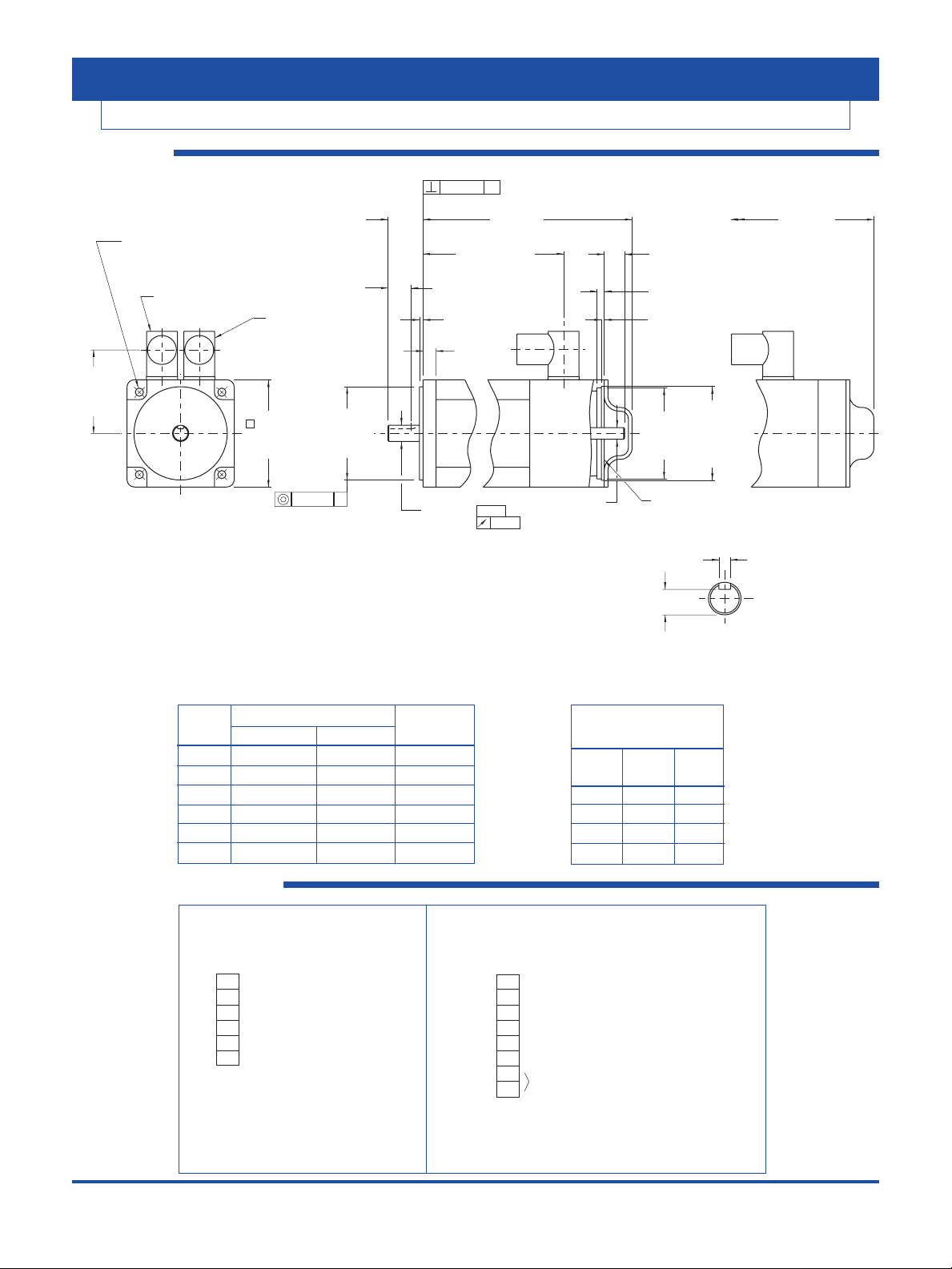
Kollmorgen GOLDLINE BH/MH
DIMENSIONS
BH/MH-12x
CONNECTOR PIN OUTS
“A” MAX.
Model without brake with brake “B” “C” “D” “E”
BH-122 204.0 (8.03) 243.8 (9.59) 159.0 (6.26) 18.0 (0.71) 23.0 (0.90) 10.997-11.008 (.4330-.4334)
BH-124 234.5 (9.23) 273.2 (10.76) 189.5 (7.46) 20.0 (0.79) 30.0 (1.18) 13.997-14.008 (.5511-.5515)
BH-126 265.0 (10.43) 303.7 (11.96) 220.0 (8.66) 20.0 (0.79) 30.0 (1.18) 13.997-14.008 (.5511-.5515)
MH-123 241.0 (9.49) 279.6 (11.01) 196.0 (7.72) 20.0 (0.79) 30.0 (1.18) 13.997-14.008 (.5511-.5515)
MH-125 283.1 (11.15) 321.7 (12.67) 238.1 (9.37) 20.0 (0.79) 30.0 (1.18) 13.997-14.008 (.5511-.5515)
MH-127 335.5 (13.21) 374.1 (14.73) 290.5 (11.44) 20.0 (0.79) 30.0 (1.18) 13.997-14.008 (.5511-.5515)
M3 X 0.5 THD X 10.0 (.39) DP.
4 PL. EQ. SPACED ON A
Ø80.00 (3.510) B.C.
4.00 (.157)
3.97 (.156)
8.50 (.335)
8.40 (.331)
KEYWAY DETAIL
BRAKE OPTION
Ø5.80 (.228) THRU
4 PL. EQ. SPACED
ON A Ø75.00 (2.953) B.C.
MIN.
2.36
"B"±1.5
(.06)
(.375)
(.093)
"D" ±.5 (.02)
.035
-A-
(.0014)
.08 TIR A
(.003)
.08 TIR A
(.003)
9.54
17.5
5.987
5.962
(.236)
(.235)
59.140
59.090
(2.328)
(2.326)
61.390
61.340
2.49
6.3
(.69)
(.25)
(.098)
SEE
NOTE #2
(2.417)
(2.415)
SEE NOTE #2
"A" MAX. "A" MAX.
WITH BRAKE
RESOLVER & THERMOSTAT
RECEPTACLE
MOTOR
RECEPTACLE
62.0
60.0
(2.44)
(2.36)
76.5
(3.01)
MAX.
71.5
70.0
(2.82)
(2.76)
60.012
59.993
(2.3627)
(2.3619)
Ø
Ø "E"
Ø
Ø
Ø
5.00 (.197)
4.97 (.196)
11.00 (.433)
10.90 (.429)
BH-122
BH-124, BH-126,
MH-123, MH-125, & MH-127
"C"
Notes:
1. Motor can be mounted in any position.
2. Counterbore for o-ring seal.
3. -61 and -71 models have been certified to meet IP65
sealing. -S model has been certified to meet IP67 sealing
and has viton shaft seal and viton o-rings.
4. -63 and -73 models meet sealing specs except for mounting face.
5. Kollmorgen approved mating plugs with filler plugs must be
installed before motor meets sealing specs.
6. Customer shaft key supplied with motor.
7. Dimensions in parentheses ( ) are in English and are for reference only.
8. Tolerances unless otherwise specified:
Metric: X decimal place ±.4 English: XX decimal places ±.015
XX decimal places ±.13 XXX decimal places ±.005
Thermostat:
Normally closed contacts
4 Amp, 120 VAC - thermostat
opens at 170ºC ±5ºC
and closes at 132ºC ±5ºC
(BH, MH-12x -- yellow leads)
Standard Options
Model Mating Shaft
No. Plugs Seal
-61 No Yes
-63 No No
-71 Yes Yes
-73 Yes No
KOLLMORGEN • keyfaith • 0755-83288220
21
Kollmorgen GOLDLINE BH/MH
DIMENSIONS
BH/MH-22x
11.2
(.44)
KEYWAY DETAIL
17.5 (.69)
3.0
(.12)
"A" MAX.
SEE NOTE #2
6.3 (.25)
2.49 (.098)
19.8
(.78)
MIN.
"B" ±1.5 (.06)
97.0
92.0
(3.82)
(3.62)
72.5
70.5
(2.85)
(2.78)
Ø7.00-7.36 (.276-.290) THRU
4 PL. EQ. SPACED
ON A Ø100.00 (3.937) B.C.
RESOLVER & THERMOSTAT
RECEPTACLE
MOTOR
RECEPTACLE
80.012
79.993
(3.1501)
(3.1493)
Ø
Ø
Ø
Ø
14.008
13.997
(.5515)
(.5511)
Ø
.035
-A-
(.0014)
30.5
29.5
(1.20)
(1.16)
78.16
78.11
(3.077)
(3.075)
11.00 (.433)
10.90 (.429)
5.00 (.197)
4.97 (.196)
80.44
80.39
(3.167)
(3.165)
SEE
NOTE #2
9.987
9.962
(.3932)
(.3922)
M5 X 0.8 THD. X 10.0 (.39)
MIN. DP. 4 PL. EQ. SPACED
ON A Ø100.00 (3.937) B.C.
BRAKE OPTION
"A" MAX.
WITH BRAKE
.08 TIR A
(.003)
.08 TIR A
(.003)
Notes:
1. Motor can be mounted in any position.
2. Counterbore for o-ring seal.
3. -61 and -71 models have been certified to meet IP65
sealing. -S model has been certified to meet IP67 sealing
and has viton shaft seal and viton o-rings.
4. -63 and -73 models meet sealing specs except for mounting face.
5. Kollmorgen approved mating plugs with filler plugs must be
installed before motor meets sealing specs.
6. Customer shaft key supplied with motor.
7. Dimensions in parentheses ( ) are in English and are for reference only.
8. Tolerances unless otherwise specified:
Metric: X decimal place ±.4 English: XX decimal places ±.015
XX decimal places ±.13 XXX decimal places ±.005
“A” MAX.
Model without brake with brake “B”
BH-222 236.2 (9.30) 276.5 (10.89) 179.7 (7.08)
BH-224 275.8 (10.86) 316.1 (12.44) 219.3 (8.63)
BH-226 315.4 (12.42) 355.1 (14.00) 258.9 (10.19)
MH-223 275.8 (10.86) 316.0 (12.44) 219.3 (8.63)
MH-225 315.4 (12.42) 355.7 (14.00) 258.9 (10.19)
MH-227 373.2 (14.69) 413.4 (16.28) 316.7 (12.47)
Connections: Motor Receptacle: Resolver & Thermostat Receptacle:
INTERCONNECTRON INTERCONNECTRON
LEOBOBKNNNNN000 SFMB12TNNNN000
Pin 3 - Phase W (brown) Pin 3 - S3 (black), Sin Lo
Pin 4 - Phase V (red) Pin 4 - S4 (blue), Cos Lo
Pin 1 - Phase U (white) Pin 5 - R2 (yellow/white), Ref. Lo
Pin 2 - Ground (green/yellow) Pin 7 - S1 (red) Sin Hi
Pin A - (Optional)Brake (blue) Pin 8 - S2 (yellow) Cos Hi
Pin B - (Optional)Brake (blue) Pin 9 - R1 (red/white), Ref Hi
(brake not polarity sensitive) Pin 2
Pin 6
CONNECTOR PIN OUTS
Thermostat:
Normally closed contacts
4 Amp, 120 VAC - thermostat
opens at 170ºC ±5ºC
and closes at 132ºC ±5ºC
(BH, MH-22x -- yellow leads)
Standard Options
Model Mating Shaft
No. Plugs Seal
-61 No Yes
-63 No No
-71 Yes Yes
-73 Yes No
KOLLMORGEN • keyfaith • 0755-83288220
22

BH/MH-42x
"B"
KEYWAY DETAIL
17.5 (.69)
2.49 (.098)
SEE NOTE #2
6.3 (.25)
±2.0 (.08)
3.5 (.14)
12.5 (.49)
"A" MAX.
118.8
115.0
(4.68)
(4.53)
84.0
(3.31)
Ø9.00-9.36 (.354-.369) THRU
4 PL. EQ. SPACED
ON A Ø130.00 (5.118) B.C.
RESOLVER & THERMOSTAT
RECEPTACLE
MOTOR
RECEPTACLE
110.013
109.991
(4.3312)
(4.3304)
Ø
Ø
24.009
23.996
(.9452)
(.9447)
37.00
(1.457)
MIN.
50.50
49.50
(1.988)
(1.949)
8.000 (.3149)
7.964 (.3135)
20.00 (.787)
19.80 (.780)
.10 TIR A
(.004)
.040
-A-
(.0016)
101.75
101.70
(4.006)
(4.004)
Ø
Ø
Ø
9.987
9.962
(.3932)
(.3922)
104.22
104.17
(4.103)
(4.101)
SEE
NOTE #2
M5 X 0.8 THD X 14.0
(.55) MIN. DP. 4 PL.
EQ. SPACED ON A
Ø130.00 (5.118) B.C.
.10 TIR A
(.004)
BRAKE OPTION
"A" MAX.
WITH BRAKE
Notes:
1. Motor can be mounted in any position.
2. Counterbore for o-ring seal.
3. -61 and -71 models have been certified to meet IP65
sealing. -S model has been certified to meet IP67 sealing
and has viton shaft seal and viton o-rings.
4. -63 and -73 models meet sealing specs except for mounting face.
5. Kollmorgen approved mating plugs with filler plugs must be
installed before motor meets sealing specs.
6. Customer shaft key supplied with motor.
7. Dimensions in parentheses ( ) are in English and are for reference only.
8. Tolerances unless otherwise specified:
Metric: X decimal place ±.4 English: XX decimal places ±.015
XX decimal places ±.13 XXX decimal places ±.005
CONNECTOR PIN OUTS
Kollmorgen GOLDLINE BH/MH
DIMENSIONS
“A” MAX.
without brake with brake “B”
BH-422 265.5 (10.45) 313.9 (12.36) 212.6 (8.37)
BH-424 318.8 (12.55) 367.3 (14.46) 265.9 (10.47)
BH-426 372.1 (14.65) 420.6 (16.56) 319.2 (12.57)
MH-423 318.8 (12.55) 367.3 (14.46) 265.9 (10.47)
MH-425 372.1 (14.65) 420.6 (16.56) 319.2 (12.57)
MH-427 444.9 (17.52) 493.4 (19.43) 392.0 (15.43)
Standard Options
Model Mating Shaft
No. Plugs Seal
-61 No Yes
-63 No No
-71 Yes Yes
-73 Yes No
Connections: Motor Receptacle: Resolver & Thermostat Receptacle:
INTERCONNECTRON INTERCONNECTRON
LEOBOBKNNNNN000 SFMB12TNNNN000
Pin 3 - Phase W (brown) Pin 3 - S3 (black), Sin Lo
Pin 4 - Phase V (red) Pin 4 - S4 (blue), Cos Lo
Pin 1 - Phase U (white) Pin 5 - R2 (yellow/white), Ref. Lo
Pin 2 - Ground (green/yellow) Pin 7 - S1 (red) Sin Hi
Pin A - (Optional)Brake (blue) Pin 8 - S2 (yellow) Cos Hi
Pin B - (Optional)Brake (blue) Pin 9 - R1 (red/white), Ref Hi
(brake not polarity sensitive) Pin 2
Pin 6
Thermostat:
Normally closed contacts
4 Amp, 120 VAC - thermostat
opens at 170ºC ±5ºC
and closes at 132ºC ±5ºC
(BH, MH-42x -- yellow leads)
KOLLMORGEN • keyfaith • 0755-83288220
23

BH/MH-62x
±2.0 [.08]
"A" MAX.
17.5 (.69)
6.3 (.25)
"B"
KEYWAY DETAIL
145.3
142.0
(5.72)
(5.59)
165.0
161.0
(6.50)
(6.34)
109.4
107.4
(4.31)
(4.23)
130.014
129.989
(5.1187)
(5.1177)
.10 TIR A
(.004)
24.009
23.996
(.9452)
(.9447)
Ø
32.018
32.002
(1.2606)
(1.2600)
Ø
.040
-A-
(.0016)
8.000
7.964
(.3149)
(.3135)
20.00 (.787)
19.80 (.780)
27.00 (1.063)
26.80 (1.055)
10.000
9.964
(.3937)
(.3923)
2.49 (.098)
SEE NOTE #2
9.987
9.962
(.3932)
(.3922)
127.15
127.10
(5.006)
(5.004)
Ø
Ø
Ø
3.5
(.14)
18.0
(.71)
37.00
(1.457)
50.50
49.50
(1.988)
(1.949)
"A" MAX.
WITH BRAKE
129.62
129.57
(5.103)
(5.101)
SEE
NOTE #2
M5 X 0.8 THD X 14.0
(.55) MIN. DP. 4 PL.
EQ. SPACED ON A
Ø164.00 (6.457) B.C.
Ø11.00 (.433) THRU
4 PL. EQ. SPACED ON
A Ø165.00 (6.496) B.C.
RESOLVER & THERMOSTAT
RECEPTACLE
BH-626, MH-623,
MH-625, & MH-627
BH-622 & BH-624
SEE KEYWAY DETAIL
.10 TIR A
(.004)
BRAKE OPTION
Notes:
1. Motor can be mounted in any position.
2. Counterbore for o-ring seal.
3. -41 and -51 models have been certified to meet IP65
sealing. -S model has been certified to meet IP67 sealing, except for PG-21,
and has viton shaft seal and viton o-rings.
4. -43 and -53 models meet sealing specs except for mounting face.
5. Kollmorgen approved cables and mating plugs with filler plugs must be
installed before motor meets sealing specs.
6. Customer shaft key supplied with motor.
7. Dimensions in parentheses ( ) are in English and are for reference only.
8. Tolerances unless otherwise specified:
Metric: X decimal place ±.4 English: XX decimal places ±.015
XX decimal places ±.13 XXX decimal places ±.005
PG-21 LIQUID TIGHT
FITTING FOR MOTOR LEADS
PG-11 LIQUID TIGHT FITTING
(5.0-9.9 (.20-.39) CABLE Ø
RANGE) WITH BRAKE OPTION
159.8
(6.29)
REF.
CONNECTOR PIN OUTS
Kollmorgen GOLDLINE BH/MH
DIMENSIONS
“A” MAX.
without brake with brake “B”
BH-622 299.2 (11.79) 355.6 (14.00) 96.8 (3.81)
BH-624 367.8 (14.48) 424.2 (16.70) 165.4 (6.51)
BH-626 436.4 (17.18) 492.8 (19.40) 234.0 (9.21)
MH-623 367.8 (14.48) 424.3 (16.70) 165.4 (6.51)
MH-625 436.4 (17.18) 492.9 (19.41) 234.0 (9.21)
MH-627 531.5 (20.93) 588.0 (23.15) 329.1 (12.96)
Connections: Motor Terminal Strip: Resolver & Thermostat Receptacle:
INTERCONNECTRON SEFA12AMREN000
Terminal U - white lead Pin 3 - S3 (black), Sin Lo
Terminal V - red lead Pin 4 - S4 (blue), Cos Lo
Terminal W - brown lead Pin 5 - R2 (yellow/white), Ref. Lo
Pin 7 - S1 (red) Sin Hi
(M6 pan head screw with external Pin 8 - S2 (yellow) Cos Hi
tooth lockwasher is provided for Pin 9 - R1 (red/white) Ref. Hi
use as a case ground.) Pin 2
Pin 6
Brake Terminal Strip:
(2) blue leads
Thermostat:
Normally closed contacts
4 Amp, 120 VAC - thermostat
opens at 170ºC ±5ºC
and closes at 132ºC ±5ºC
(BH, MH-62x -- yellow leads)
Standard Options
Model Mating Shaft
No. Plugs Seal
-41 No Yes
-43 No No
-51 Yes Yes
-53 Yes No
KOLLMORGEN • keyfaith • 0755-83288220
24

“A” MAX.
without brake with brake “B” “C” “D” “E”
BH-822 360.4 (14.19) 416.9 (16.41) 158.3 (6.23) 39.00 (1.535) 58.00 (2.283) 32.002-32.018 (1.2600-1.2606)
MH-823 449.9 (17.71) 506.4 (19.94) 247.8 (9.76) 54.00 (2.126) 82.00 (3.228) 48.002-48.018 (1.8898-1.8905)
BH-826 520.2 (20.48) 595.9 (23.46) 337.3 (13.28) 54.00 (2.126) 82.00 (3.228) 48.002-48.018 (1.8898-1.8905)
MH-827 648.7 (25.54) 686.0 (27.01) 446.6 (17.58) 54.00 (2.126) 82.00 (3.228) 48.002-48.018 (1.8898-1.8905)
Kollmorgen GOLDLINE BH/MH
DIMENSIONS
CONNECTOR PIN OUTS
BH/MH-82x
Connections: Motor Terminal Strip: Resolver & Thermostat Receptacle:
INTERCONNECTRON SEFA12AMREN000
Terminal U - white lead Pin 3 - S3 (black), Sin Lo
Terminal V - red lead Pin 4 - S4 (blue), Cos Lo
Terminal W - brown lead Pin 5 - R2 (yellow/white), Ref. Lo
Pin 7 - S1 (red) Sin Hi
(M6 pan head screw with external Pin 8 - S2 (yellow) Cos Hi
tooth lockwasher is provided for Pin 9 - R1 (red/white) Ref. Hi
use as a case ground.) Pin 2
Pin 6
Brake Terminal Strip:
(2) blue leads
Thermostat:
Normally closed contacts
4 Amp, 120 VAC - thermostat
opens at 170ºC ±5ºC
and closes at 132ºC ±5ºC
(BH, MH-82x -- yellow leads)
Standard Options
Model Mating Shaft
No. Plugs Seal
-41 No Yes
-43 No No
-51 Yes Yes
-53 Yes No
KOLLMORGEN • keyfaith • 0755-83288220
25
Ø14.00 (.551) THRU
4 PL. EQ. SPACED ON
A Ø215.00 (8.464) B.C.
RESOLVER & THERMOSTAT
RECEPTACLE
133.4
131.4
(5.25)
(5.17)
PG-11 LIQUID TIGHT FITTING
(5.0-9.9 (.20-.39) CABLE Ø
RANGE) WITH BRAKE OPTION
PG-21 LIQUID TIGHT
FITTING FOR MOTOR LEADS
189.0
185.0
(7.44)
(7.28)
Ø
192.4
190.0
(7.57)
(7.48)
180.014
179.989
(7.0872)
(7.0862)
19.0
(.75)
.10 TIR A
(.004)
(.02)
"C"
"D"
±.5
±2.0 [.08]
"B"
4.0
(.16)
"A" MAX.
17.5 (.69)
7.5 (.30)
3.68 (.145)
SEE NOTE #2
171.58
Ø
171.53
(6.755)
(6.753)
WITH BRAKE
BRAKE OPTION
"A" MAX.
.10 TIR A
Notes:
1. Motor can be mounted in any position.
2. Counterbore for o-ring seal.
3. -41 and -51 models have been certified to meet IP65 sealing.
-S model has been certified to meet IP67 sealing, except for PG-36,
and has viton shaft seal and viton o-rings.
4. -43 and -53 models meet sealing specs except for mounting face.
5. Kollmorgen approved cables and mating plugs with filler plugs must be
installed before motor meets sealing specs.
6. Customer shaft key supplied with motor.
7. Dimensions in parentheses ( ) are in English and are for reference only.
8. Tolerances unless otherwise specified:
Metric: X decimal place ±.4 English: XX decimal places ±.015
XX decimal places ±.13 XXX decimal places ±.005
(.004)
Ø"E"
-A .050
(.002)
27.00 (1.063)
26.80 (1.055)
M5 X 0.8 THD X 14.0
(.55) MIN. DP. 4 PL.
EQ. SPACED ON A
Ø227.00 (8.937) B.C.
10.000
9.964
(.3937)
(.3923)
42.50 (1.673)
42.30 (1.665)
KEYWAY DETAIL
MH-823BH-822
9.987
Ø
9.962
(.3932)
(.3922)
Ø
NOTE #2
14.000
13.957
(.5512)
(.5495)
175.51
175.46
(6.910)
(6.908)
SEE

*Motor Continuous Peak Continuous Max Amplifier Amplifier **Cable Set Curve
Torque Torque Power Speed
Cont/
Peak Current Number
lb-ft (N-m) lb-ft
(N-m)
HP (kW) RPM (RMS/Phase)
BH-122-A-61
MH-123-A-61 0.52 (0.70) 1.77 (2.40) 0.54 (0.41) 7500 S60301 3/6 CS-SS-RHG1HE-xx 1
BH-124-B-61
MH-125-B-61 1.00 (1.35) 3.10 (4.20) 1.11 (0.83) 7500 S60301 3/6 CS-SS-RHG1HE-xx 2
BH-126-B-61
MH-127-B-61 1.40 (1.90) 3.10 (4.20) 1.6 (1.2) 7500 S60301 3/6 CS-SS-RHG1HE-xx 3
BH-222-E-61
MH-223-E-61 1.5 (2.1) 3.5 (4.8) 1.9 (1.4) 7000 S60301 3/6 CS-SS-RHG1HE-xx 4
BH-224-G-61
MH-225-G-61 2.8 (3.8) 5.4 (7.3) 2.1 (1.6) 4600 S60301 3/6 CS-SS-RHG1HE-xx 5
BH-226-C-61
MH-227-C-61 4.1 (5.6) 10.5 (14.2) 2.9 (2.2) 4900 S60601 6/12 CS-SS-RHG1HE-xx 6
BH-226-E-61
MH-227-E-61 4.1 (5.6) 7.7 (10.5) 2.2 (1.7) 3200 S60301 3/6 CS-SS-RHG1HE-xx 7
BH-422-D-61
MH-423-D-61 4.3 (5.8) 12.2 (16.5) 2.8 (2.1) 4600 S60601 6/12 CS-SS-RHG1HE-xx 8
BH-424-D-61
MH-425-D-61 7.8 (10.6) 14.7 (20.0) 4.4 (3.3) 3700 S60601 6/12 CS-SS-RHG1HE-xx 9
BH-426-B-61
MH-427-B-61 11.7 (15.8) 27.4 (37.1) 5.7 (4.2) 3200 S61001 10/20 CS-SS-RHG1HE-xx 10
BH-426-C-61
MH-427-C-61 11.4 (15.5) 24.5 (33.2) 7.9 (5.9) 5000 S61401 14/28 CS-SS-RHG2HE-xx 11
BH-622-A-41
MH-623-A-41 10.8 (14.6) 29.5 (40.0) 3.3 (2.5) 2000 S60601 6/12 CS-SS-RHG2UE-xx 12
BH-622-B-41
MH-623-B-41 11.0 (14.9) 24.7 (33.5) 5.9 (4.4) 4000 S61001 10/20 CS-SS-RHG2UE-xx 13
BH-624-C-41
MH-625-C-41 18.6 (25.2) 41.4 (56.2) 9.5 (7.1) 4500 S62001 20/40 CS-SS-RHG2UE-xx 14
BH-624-D-41
MH-625-D-41 18.9 (25.6) 40.4 (54.8) 8.4 (6.3) 3300 S61401 14/28 CS-SS-RHG2UE-xx 15
BH-624-E-41
MH-625-E-41 18.2 (24.7) 34.5 (46.8) 9.8 (7.3) 3850 S61401 14/28 CS-SS-RHG2UE-xx 16
BH-624-G-41
MH-625-G-41 18.2 (24.7) 34.5 (46.8) 6.2 (4.6) 2600 S61001 10/20 CS-SS-RHG2UE-xx 17
BH-626-C-41
MH-627-C-41 27.0 (36.6) 61.1 (82.9) 6.5 (4.9) 1550 S61001 10/20 CS-SS-RHG2UE-xx 18
BH-626-E-41
MH-627-E-41 26.1 (35.4) 50.2 (68.0) 14.1 (10.5) 3700 S62001 20/40 CS-SS-RHG2UE-xx 19
BH-822-C-41
MH-823-C-41 25.7 (34.8) 60.2 (81.6) 6.3 (4.70) 1600 S61001 10/20 CS-SS-RHG2UE-xx 20
BH-822-D-41
MH-823-D-41 25.6 (34.7) 53.6 (72.7) 11.4 (8.5) 3000 S62001 20/40 CS-SS-RHG2UE-xx 21
BH-826-A-41
MH-827-A-41 69.0 (93.5) 120.1 (162.8) 15.3 (11.4) 1500 S62001 20/40 CS-SS-RHG2UE-xx 22
SYSTEM SUMMARY
Kollmorgen GOLDLINE BH/MH and SERVOSTAR 600
System Summary and Configurations
Notes: *All motors have resolver feedback. **Cable “xx” designation denotes length= 01, 03, 06, 09 meters
KOLLMORGEN • keyfaith • 0755-83288220
26

ORDERING INFORMATION
Kollmorgen GOLDLINE BH/MH and SERVOSTAR 600
Model Number Description
External Regen Resistors (in housing): BAR-250 250 watts
BAR-500 500 watts
BAR-1500 1500 watts
Communications Cables: A-97251-004 RS-232 (9 pin) communication cable
A-SR6Y Y- adapter cable with 5 DB9 connectors for connecting PC
up to 4 drives, includes termination
SERVOSTAR 600 Option Slot: I/O Extension Card S6xxxx-EI
BH - 82 2 x - C - 4 1 B231a- 100
b
Brushless Motor Sequential Specials
(With frameless resolver)
BH-Low Inertia Series Standard Additions
MH-Medium Inertia Series B2 - 90 VDC fail-safe brake
B3 - 24 VDC fail-safe brake
Motor Frame E1 - Encoder adapter and/or encoder
12, 22, 42, 62, 82 Exxx - Special adapter and/or encoder
S - IP67 sealing (Viton) available on 12, 22, 42 models
Stack Length 62 and 82 models IP67 except for PG21 & 36 fittings
2, 4, 6 - B Series
3, 5, 7 - M Series Mounting and Shaft Seal Options:
1 - Std. metric mount with IP65 sealing and rear shaft extensions
S-Non-UL recognized models only 3 - Same as 1, except w/o front shaft seal
Winding Connector (ref. outline drawing) pages 18-22
A, B, etc.
a
Omit when no
standard additions
are used
b
Omit if not special
Note:BH/MH Series motors are available with custom mechanicals including special shafts and keyways.
Contact the Kollmorgen Customer Support Network (1-800-77 SERVO) for more information.
S
6 xx 01-xx
SERVOSTAR Family Option Slot
NA - No Option
600 Series EI - Extended I/O
Current Rating (Cont. Arms/Ø) Configuration
03 - 3.0 amps 01 - Standard
06 - 6.0 amps
10 - 10.0 amps
14 - 14.0 amps
20 - 20.0 amps
SERVOSTAR 600 ORDERING INFORMATION
Kollmorgen GOLDLINE®BH ORDERING INFORMATION
KOLLMORGEN • keyfaith • 0755-83288220
27

Kollmorgen Sales Offices
E-mail: servo@kollmorgen.com
Internet: http://www.kollmorgen.com
Motion Technologies Group
1-800-77 SERVO
E-mail: servo@kollmorgen.com
Americas Europe & Middle East
Radford, VA Duesseldorf, Germany
Tel: (800) 77 SERVO Tel: (49) 203 9979 0
Fax: (540) 639-1640 Fax: (49) 203 9979 155
Kollmorgen Manufacturing Locations
Kollmorgen Artus Kollmorgen PMI
Avrillé, France Commack, NY
Ho Chi Minh City, Vietnam
Kollmorgen Electro-Optical Kollmorgen Seidel
Northampton, MA Duesseldorf, Germany
Kollmorgen Industrial Drives Kollmorgen Servotronix
Radford, VA Tel Aviv, Israel
Kollmorgen Inland Motor Kollmorgen Tandon Inc
Radford, VA Bombay, India
Kollmorgen enjoys a reputation of excellence based on constant endeavors to
update products. Information in this brochure is subject to change.
Windows is a registered trademark of Microsoft Corporation.
Kollmorgen SERVOSTAR
®
600, MOTIONLINK®, Kollmorgen GOLDLINE,
and MOTIONEERING are trademarks of Kollmorgen.
 Loading...