

Page 1

V ersion 1.0
Page 2

2
Page 3

3
Table of contents
1. Safety instructions......................................................................................................... 3
2. Operating dete rminations ............................................................................................. 4
3. Description of the device .............................................................................................. 5
4. Inst allation...................................................................................................................... 6
4.1Fitting the lamp........................................................................................................... 6
4.2 Lamp adjustment:...................................................................................................... 7
4.3 Inserting/Exchanging rotating gobos......................................................................... 7
4.4 Rigging the fixture .....................................................................................................8
4.5 Connection to the mains........................................................................................... 9
4.6 DMX-512 connection/connectio n be tw een fi xtu re s ...................................................9
5. DMX PR O T OCOL.......................................................................................................... 10
6. Addressing................................................................................................................... 13
7. Remotely controllable functions ................................................................................ 13
7.1 Lamp .......................................................................................................................13
7.2 Switching On and Off the lamp by t he control board................................................ 13
7.3 Colour wheels ......................................................................................................... 13
7.4 Static gobo wheel.................................................................................................... 13
7.5 Rotating gobo wheel ...............................................................................................14
7.6 3-facet rotating prism............................................................................................... 14
7.7 Iris ........................................................................................................................... 14
7.8 Focus-multistep zoom ............................................................................................. 14
7.9 Dimmer/Shutt er/Strobe............................................................................................14
7.10 F an........................................................................................................................ 14
8. Control Board .............................................................................................................. 14
8.1 Main functions ......................................................................................................... 14
8.2 SPEC - Special functions........................................................................................ 16
9. Error and information messages................................................................................ 22
10.T echnical specificati ons ............................................................................................23
11. Maintenance and cleaning ........................................................................................ 25
12. Appendix .................................................................................................................... 25
Page 4

4
CAUTION!
Keep this device away from rain and moisture!
Unplug mains lead before opening the housing!
FOR YOUR OWN SAFETY, PLEASE READ THIS USER MANUAL CAREFULLY
BEFORE YOU INITIAL START - UP!
1. Safety instructions
Every person involv ed with installation and maintenance of this de vice ha v e to:
- be qualilfied
- follow the instructions of this manual
Caution ! Be careful with your operations.
With a voltage of 230V you can suffer
a dangerous electric shock when touching the wires!
This device has left our premises in absolutely perf ect condition. In order to maintain this condition and to ensure
a safe operation, it is absolutely necessary for the user to follo w the safety instructions and warning notes written
in this manual.
Important:
The manufacturer will not accept liability f or any resulting damages caused by the non-observance of this manual
or any unauthorized modification to the device.
Please consider that damages caused by manual modifications to the device are not subject to w arranty.
Never let the po wer-cord come into contact with other cables! Handle the power-cord and all connections with
the mains with particular caution!
Always plug in the power plug last. Make sure that the power-switch is set to OFF-position before you connect
the device to the mains. The pow er-plug has to be accessib le after installing the de vice .
Make sure that the power-cord is nev er crimped or damaged by sharp edges. Check the device and the pow er-
cord from time to time.
Always disconnect from the mains, when the device is not in use or before cleaning it. Only handle the power-
cord by the plug. Never pull out the plug by tugging the power-cord.
This device falls under protection class I. Theref ore it is essential to connect the yello w/green conductor to earth.
The electric connection, repairs and servicing must be carried out by a qualified employee.
Do not connect this device to a dimmer pack.
Do not switch the fixture on and off in short intervals as this would reduce the lamp’s lif e.
During the initial start-up some smoke or smell may arise. This is a normal process and does not necessarily
mean that the device is def ectiv e.
Do not touch the device’ s housing with bare hands during its oper ation (housing becomes hot)!
For replacement use lamps and fuses of the same type and rating only.
CAUTION ! EYEDAMAGES !
Avoid looking directly into the light source
(meant especially for epileptics) !
Page 5

5
2. Operating determinations
This device is a moving-head spot f or creating decorative effects and was designed for indoor use only.
If the device has been exposed to drastic temper ature fluctuation (e .g. after transportation), do not switch it on
immediately. The arising condensation water might damage your device. Leave the device switched off until it
has reached room temperature.
Never run the device without lamp!
Do not shake the device . Avoid brute f orce when installing or operating the de vice .
Never lift the fixture by holding it at the projector-head, as the mechanics may be damaged. Always hold the
fixture at the transport handles.
When choosing the installation-spot, please make sure that the device is not e xposed to extreme heat, moisture
or dust.There should not be any cables lying around. You endanger your own and the safety of others!
The minimum distance between light-output and the illuminated surface must be more than 1 meter.
Make sure that the area below the installation place is bloc ked when rigging, derigging or servicing the fixture.
Always fix the fixture with an appropriate safety-rope . Fix the safety-rope at the correct eye bolt only.
Only operate the fixture after having checked that the housing is firmly closed and all screws are tightly fast ened.
The lamp must never be ignited if the objective-lens or any housing-cover is open, as discharge lamps may
explose and emit a high ultraviolet radiation, which ma y cause b urns.
The maximum ambient temperature
t
a
= 40° C must never be e xceeded. Otherwise, the lamp is switched off and
the fixture is out of operation for 5 minutes.
Allow the fixture to cool for at least 15 minutes bef ore replacing the lamp .
CAUTION!
The lens has to be replaced when it is obviously damaged,
so that its function is impaired, e. g. due to cracks or deep scratches!
Operate the device only after having familiarized with its functions. Do not permit operation by persons not
qualified for operating the de vice. Most damages are the result of unprofessional operation!
CAUTION!
The lamp has to be replaced when it is damaged
or deformed due to the heat!
Please use the original packaging if the device is to be transported.
Please consider that unauthorized modifications on the device are forbidden due to safety reasons!
If this device will be operated in any way different to the one described in this manual, the product may suffer
damages and the guarantee becomes void. Furthe rmore, any other operation may lead to dangers like shortcircuit, burns, electric shock, burns due to ultraviolet radiation, lamp explosion, crash etc.
Page 6
6
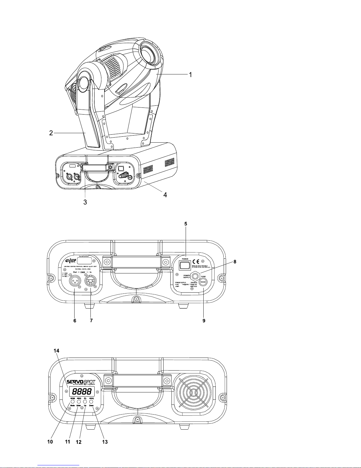
1 - Moving head
2 - Y oke
3 - Carrying handles
4 - Base
3. Description of the device
Rear panel:
5 - Power switch
6 - DMX output
7 - DMX input
8 - Power cord
9 - Fuse holder
Front panel:
10 - Mode-button
11 - Enter-button
12 - Up-button
13 - Down-button
14 - Display
Page 7

7
4. Installation
4.1Fitting the lamp
DANGER !
Install the lamps with the device switched off only .
Unplug from mains before !
T o insert the lamp OSRAM HSR 575/2 95V/575W GX-9,5 or PHILIPS MSR 575/2 95V/575W GX-9,5 , MSD 575
95V/575W GX-9,5 loosen the lamp cover at the rear of head (see the drawings ) by remowing the 3 fastening
screws which are marked "X,Y,Z".Carefully pull out the cover with the lamp socket assembly.If changing the
lamp, remove the old lamp from the soc k et. Insert the lamp to the socket.
Do not install a lamp with a higher wattage! A lamp like this generates temperatures the de vice is not designed for .Damages caused b y non-observance are not subject to warran ty. Please follow the lamp
manufacturer‘s notes!Do not touch the glass-bulb with bare hands during the installation! Make sure that the
lamp is installed tightly into the lampholder system.
Reclose the lamp cover and tighten the 3 screws.
Before striking the lamp, reset the "LAti" counter in the main menu of the Control Board, b y pressing the
"Up" and "Down" buttons in one time and then confirming with the Enter-button.
Adjust the lamp position by turning the screw "A,B,C" (see "Lamp adjustment " below).
Do not operate this fixture with opened housing-cover!
Lamp assembly:
3 phillips screws "X,Y,Z"
Lamp cover
Page 8

8
4.2 Lamp adjustment:
The ServoSpot 575 lampholder is aligned at the factory . Due to differences between lamps , fine adjustment may
improve light perf ormance.
Strike the lamp,open the shutter and the iris,set the dimmer intensity onto 100% and focus the light on a flat
surface (wall).Center a hot-spot(the brightest part of the image) by using the 3 adjustment screws "A,B,C".Turn
one screw after another a quarter-turn clokwise(counter-clokwise) to set the hot-spot in the center of the image.If
you cannot detect the hot-spot,adjust the lamp until the light is ev enly distributed.
4.3 Inserting/Exchanging rotating gobos
DANGER!
Install the gobos with the device switched off only.
Unplug from mains before!
If you wish to use other forms and patterns as the standard-gobos, or if gobos are to be e xchanged, open the top
cover of the head by loosening 2 scre ws on the top co v er.
Remove the fixation ring with an appropriate tool. Remov e the gobo and insert the new gobo . Press the fixation
ring together and insert it in the front of the gobo.
CAUTION!
Never unscrew the screws of the rotating gobo
as the ball bearing will otherwise be opened!
3 adjustment screws "A,B,C"
Page 9
9
4.4 Rigging the fixture
Danger of fire !
When installing the device, make sure there is no highly inflammable
material (decoration articles, etc.) in between a distance of min. 0,5 m.
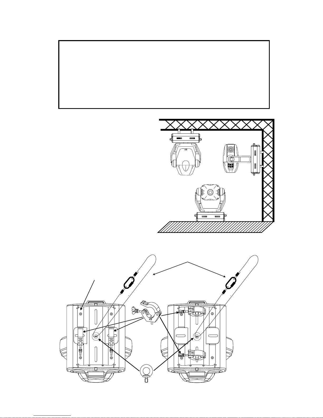
Warning ! Use 2 clamps to rig the fixture on the truss.
Follow the instructions mentioned at the bottom of the base.
Make sure that the device is fixed properly! Ensure that
the structure (truss) to which you are attaching the fixtures is secure.
The ServoSpot 575 can be placed directly on the
stage floor or rigged in any orientation on a truss
without altering its operation characteristics (see the
drawing).
The fixture’s base enables to be mounted in two w ays.
Use the clamps with screws M12.
Fix a mounting plate and an eye bolt (a part of
delivery) on the underside of the base(see the drawing
below).
Fasten a safety chain to eye bolt.The safety
chain(cord) must hold at least 10 times the weight of
the fixture. Never use the carrying handles for
secondary attachment.
Secure chain
Clamp
Eye bolt
Mounting plate
Page 10
10
4.5 Connection to the mains
Connect the fixture to the mains with the enclosed power-plug.
The earth has to be connected!
The occupation of the connection-cables is as follows:
Cable Pin International
Brown Live L
Blue Neutral N
Yellow/Green Earth
4.6 DMX-512 connection/connection between fixtures
The wires must not come into contact with each other, otherwise
the fixtures will not work at all, or will not work properly.
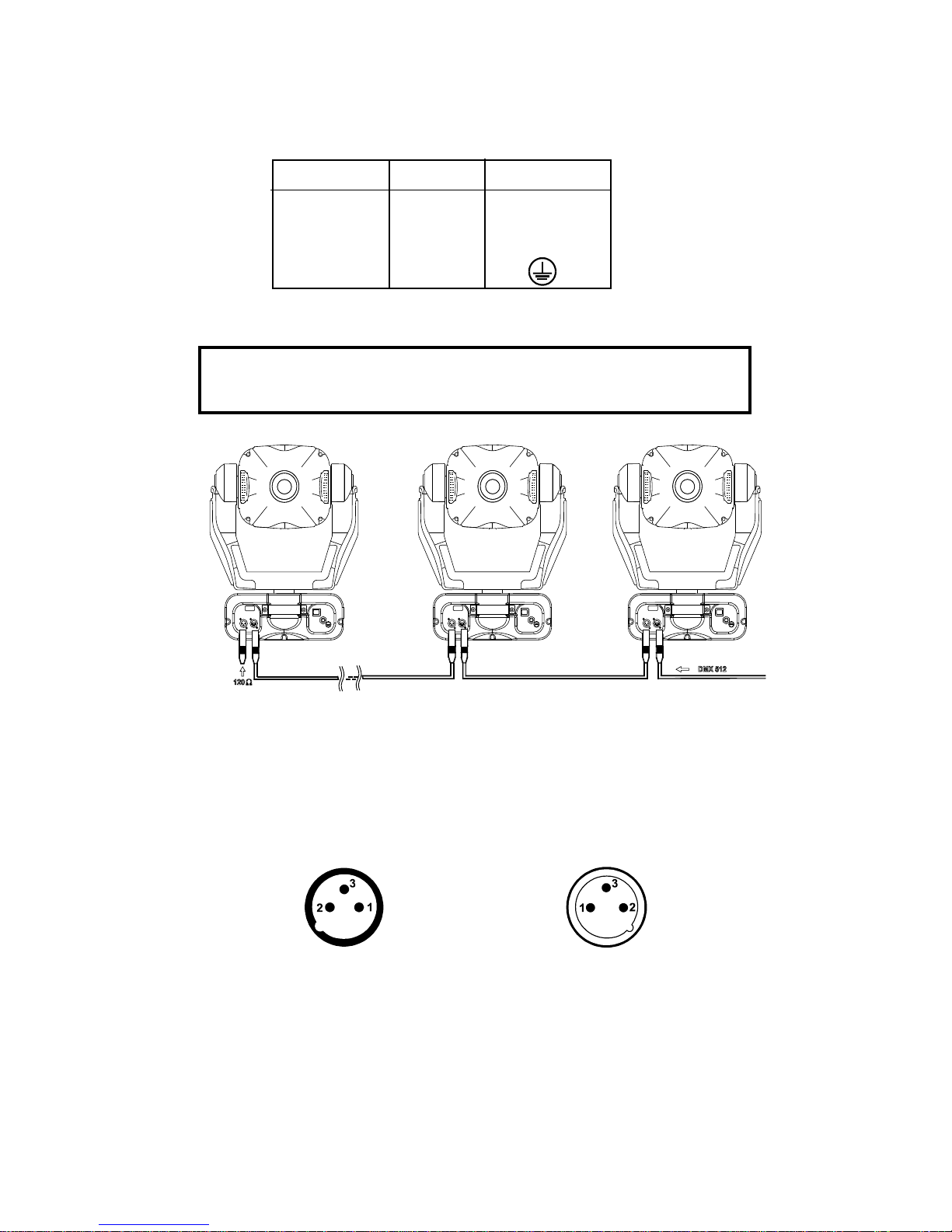
Only use a stereo shielded cable and 3-pin XLR-plugs and connectors in order to connect the controller with the
fixture or one fixture with another.
Occupation of the XLR-connection:
DMX - output DMX-input
XLR mounting-socket: XLR mounting-plug:
If you are using the standard controllers, you can connect the DMX-output of the controller directly with the
DMX-input of the first fixture in the DMX-chain. If you wish to connect DMX-controllers with other XLR-outputs,
you need to use adapter-cables.
Building a serial DMX-chain:
Connect the DMX-output of the first fixture in the DMX-chain with the DMX-input of the next fixture. Always
connect one output with the input of the next fixture until all fixtures are connected.
Caution: At the last fixture, the DMX-cable has to be terminated with a terminator. Solder a 120 Ohm resistor
between Signal (–) and Signal (+) into a 3-pin XLR-plug and plug it in the DMX-output of the last fixture.
1 - Ground
2 - Signal (-)
3 - Signal (+)
1 - Ground
2 - Signal (-)
3 - Signal (+)
Page 11
11
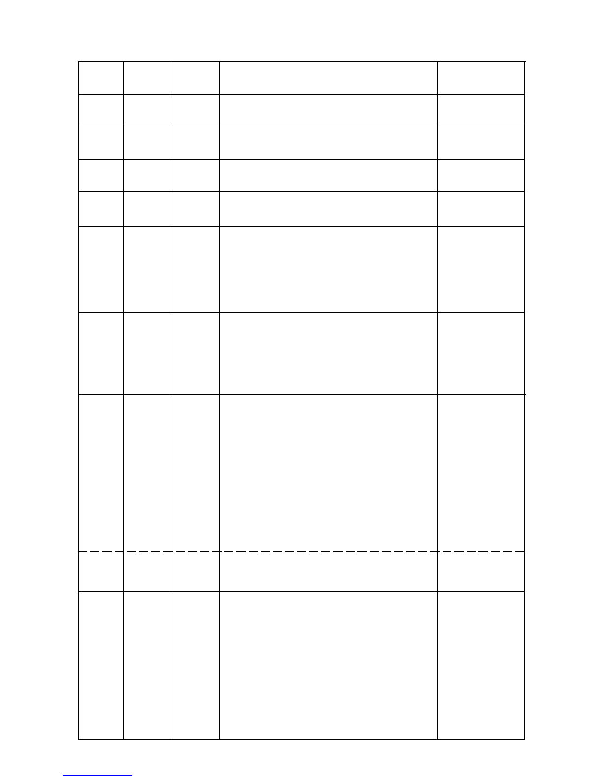
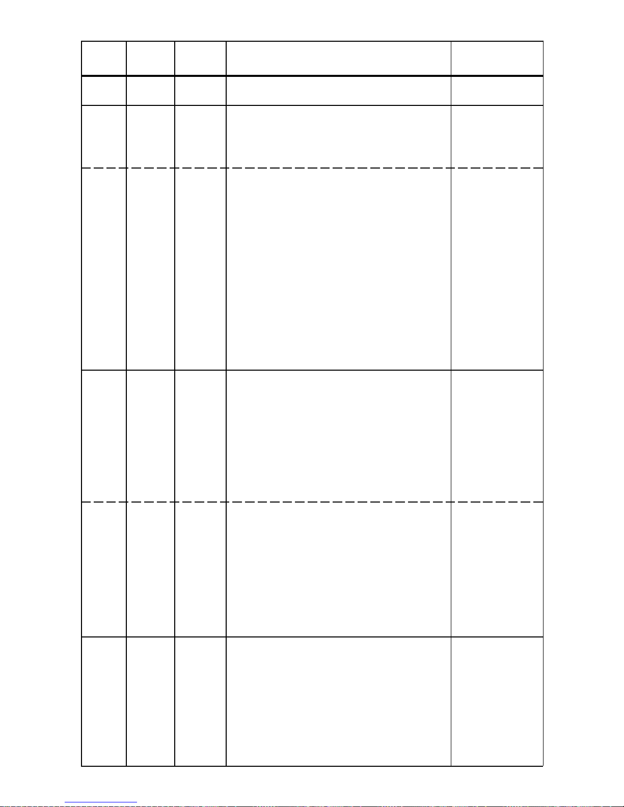
5. DMX PROTOCOL
Channel Channel Value Function Type of control
16 bit 8 bit
11 Pan
0-255 Pan mov ement b y 530° proportional
2 Pan fine
0-255 Fine control of pan movement proportional
3 2 Tilt
0-255 Tilt movement by 280° proportional
4 Tilt fine
0-255 Fine control of tilt movement proportional
5 3 Speed of PAN/TIL T mo vement
0 Max. speed (trac king mode) step
1-249 From max. speed to min.speed (vector mode) proportional
250-252 Max. speed,(track.mode),black-out while color or step
gobo changes
253-255 Max.speed (vector mode),black out while pan/tilt step
moving or color/gobo changes
6 4 Lamp on/off,reset,fans speed control
0-127 From max.speed of f an to min. speed of fan proportional
128-139 Lamp on,reset, step
140-229 No function step
230-239 Lamp off after 3 sec step
240-255 No function step
7 5 Colours 1
0 Open/white proportional
13 Light blue proportional
26 Red proportional
38 Blue proportional
51 Light green proportional
64 Yel low proportional
77 Magenta proportional
90 Cyan proportional
102 Green proportional
115 Orange proportional
128-190 Forwards rai nbow effect from fast to slow proportional
191-193 No rotation step
194-255 Backwards rainbow effect from slow to f ast pr op ortional
0-255 Colour macro function (channel 8 set from 128- proportional
255)-64 different colours in f ollowing order:white,
pink,magenta,red,orange,yellow ,green,cy an,blue,UV
8 6 Colours 2
0-11 White step
12-23 Deep red step
24-35 Deep blue step
36-47 Pink step
48-59 Cyan step
60-71 Magenta step
72-83 Y el low step
84-95 5600K correction filter step
96-107 3200K correction filter step
108-119 UV filter step
Page 12
12
Channel Channel Value Function Type of control
16 bit 8 bit
120-127 White step
128-255 Enable macro color function on channel 7 step
9 7 3-facet prism rotatin control,Prism macr os
0 Open position (no prism) step
1- 63 Forwards rotation from fast to slow proportional
64 No rotation step
65-127 Backwards rotation from slow to fast proportional
128-255 Prism/gobo macros
128-135 Macro 1 step
136-143 Macro 2 step
144-151 Macro 3 step
152-159 Macro 4 step
160-167 Macro 5 step
168-175 Macro 6 step
176-183 Macro 7 step
184-191 Macro 8 step
192-199 Macro 9 step
200-207 Macro 10 step
208-215 Macro 11 step
216-223 Macro 12 step
224-231 Macro 13 step
232-239 Macro 14 step
240-247 Macro 15 step
248-255 Macro 16 step
10 8 Static gobos
0-7 Open/hole step
8-15 Gobo 1 step
16-23 Gobo 2 step
24-31 Gobo 3 step
32-39 Gobo 4 step
40-47 Gobo 5 step
48-55 Gobo 6 step
56-63 Gobo 7 step
64-71 Gobo 8 step
72-79 Gobo 9 step
80-223 Shaking gobos with variable speed
80-95 Gobo 1 step
96-111 Gobo 2 step
112-127 Gobo 3 step
128-143 Gobo 4 step
144-159 Gobo 5 step
160-175 Gobo 6 step
176-191 Gobo 7 step
192-207 Gobo 8 step
208-223 Gobo 9 step
224-255 Gobo wheel rotation from slow to fast proportional
11 9 Rotating gobos
0-31 Open/hole step
32-63 Rot.gobo 1 (metal) step
64-95 Rot.gobo 2 (metal) step
96-127 Rot.gobo 3 (metal) step
128-159 Rot.gobo 4 (dichroic) step
160-191 Rot.gobo 5 (dichroic) step
192-223 Rot.gobo 6 (glass) step
224-255 Rot.gobo wheel cont.rotation from slow to fast proportional
Page 13

13
Channel Channel Value Function Type of control
16 bit 8 bit
12 10 Rotating gobo index,rotating gobo rotation
0-127 Gobo indexing proportional
128-190 Forwards gobo rotation from fast to slow proportional
191-192 No rotation step
193-255 Backwards gobo rotation from slow to fast proportional
13 11 Iris
0 Open step
1-179 Max.diameter to min.diameter proportional
180-191 Closed step
192-223 Pulse closing from slow to fast proportional
224-255 Pulse opening from fast to slow proportional
14 12 Focus,multistep zoom
0-85 Zoom 15°-Continuous adjustment from far to near proportional
86-170 Zoom 18°-Continuous adjustment from far to near proportional
171-225 Zoom 22°-Continuous adjustment from far to near proportional
15 13 Shutter,strobe
0-31 Shutter closed step
32-63 No function (Shutter open) step
64-95 Strobe-effect from slow to fast (max.10 flashes/s) proportional
96-127 No function (Shutter open) step
128-159 Pulse-effect in sequences from slo w to fast proportiona l
160-191 No function (Shutter open) step
192-223 Random strobe-effect from slow to fast proportional
224-255 No function (Shutter open) step
16 14 Dimmer intensity
0-255 Gradual adjustment of the dimmer intensity proportional
from 0 to 100%
Page 14

14
6. Addressing
The control board on the front panel of the ServoSpot 575 allows you to assign the DMX fixture address, which
is defined as the first channel from which the ServoSpot 575 will respond to the controller.
If you set, for ex ample, the address to channel 5, the ServoSpot 575 will use the channel 5 to 20 f or control.
Please, be sure that you don’t hav e any o verlapping channels in order to control each ServoSpot 575 correctly
and independently from any other fixture on the DMX data link.
If two, three or more ServoSpot 575 are addressed similarly, they will work similarly.
For address setting follow this procedure:
1) Switch On the ServoSpot 575 and wait until the fixture reset has finished ("rSt" is flashing at the display).
2) Press the [Mode] key in order to access the main menu. Browse through the menu by pressing the [Up]
and [Down] keys until the displa y shows "A001". Confirm by pressing [Enter] ke y and the letter "A" will flash.
3) Use the [Up] and [Down] keys to select the desired address .
4) Confirm by pressing [Enter] or [Mode] to cancel.
Controlling:
After having addressed all ServoSpot 575 , you may n ow start operating these via your lighting controller.
Note: After switching on, the ServoSpot 575 will automatically detect whether DMX 512 data is received or not.
If there is no data received at the DMX-input, the display will start to flash "A001" with actually set address.
This situation can occur if:
- the 3 PIN XLR plug (cable with DMX signal from controller) is not connected with the input of the device
- the controller is switched off or defective, if the cable or connector is defective or the signal wires are
swap in the input connector .
Note: It’s necessary to insert the XLR termination plug (with 120 Ohm) in the last lighting in the link in order to
ensure proper transmission on the DMX data link.
7. Remotely controllable functions
7.1 Lamp
The ServoSpot 575 is run with a PHILIPS MSD 575,MSR 575/2 or OSRAM HSR 575/2 lamp.
A relay inside of the ServoSpot 575 allows you to s witch On and Off the lamp via itself control board on the front
panel of base or via your controller without affecting the rest of the lighting.
7.2 Switching On and Off the lamp by the control board
1. Switch On the ServoSpot 575 and wait until the fixture reset has finished.
2. Press the [Mode] key in order to access the main menu. Browse through the men u by pressing the [Up] and
[Down] keys until the displa y shows "LAMP". Confirm by pressing [Enter] key.
3. Use the [Up] and [Down] k eys to select "On" for switch On the lamp and "Off" for switch Off the lamp and
press [Enter] to confirm or [Mode] to cancel.
Note: It is also important to note, that the discharge lamp is cold restrike types, that means, that they ha ve to be
cold before re-striking. For this reason, you have to wait 5 minutes (max. speed of fan must be adjusted) after
having switched Off the lamp before you can switch it back On again. If you try to switch On the lamp within 5
minutes after having switched it Off, the ServoSpot 575 will store this information and automatically ignite the
lamp when the 5 minutes period has expired. The message "HEAt" will appear on the control board display of
the ServoSpot 575. If the ignition of the lamp is se ven times unsuccessful, on the display will appear "LA.Er",
meaning that the lamp could be damaged or even missed, or there could be a f ailure on the ignitor or ballast.
7.3 Colour wheels
The ServoSpot 575 contains two colour wheels both with 10 color positions - 9 of these with dichroic colors and
the last one white. The wheel 1 can be positioned between two adjacent colors in any position. It is also possible
to rotate the color wheel 1 continuously at different speeds("Rainbow effect“ in both directions). Hot and cold
colour temperature filters (3200K and 5600K) and UV filtr are situated on the colour wheel 2.
By color macro function it is possible to obtain 64 different colours in f ollo wing order: white , pink, magenta, red,
orange, yell ow, green, cyan, b lue, UV
7.4 Static gobo wheel
The wheel has 9 metal gobos plus an open position.Adjustable gobo wheel rotation from slow to fast,gobo-shake
function.
Page 15

15
7.5 Rotating gobo wheel
The rotating gobo wheel includes 3 metal gobos, 1 glass gobo and 2 dichroic gobos rotating in both directions,
indexable, rotating gobo wheel contin uousli rotation from slow to f ast. The rotating gobos can be interchanged.
7.6 3-facet rotating prism
The 3-facet prism rotating in both directions at different speeds,16 prism-gobo macros
7.7 Iris
Motorized adjustable iris,variable pulse eff ects.
7.8 Focus-multistep zoom
Motorized focus enables the beam to be focused an ywhere on stage at different beam angles: 15°,18°,22°,pro vided
by the special multistep zoom.
7.9 Dimmer/Shutter/Strobe
Smooth 0 - 100 % dimming is provided by the combined mechanical dimmer/shutter unit. This unit may also be
used for strobe effect (1 - 10 flashes per second)
7.10 Fan
The ServoSpot 575 is cooled by three axial fans - two in the projector head and one in the base. The speed of
the fan (and of course the noise) can be continuously reduced if very quiet performance is required.
By the Control Board using the "F AnS" function you can choose 5 types of lo w fan speed operating:
1. "HIGH" - high (max.) speed of fans
The cooling fans w ork on max. speed (max. cooling)
2. "rEG" - continuous controlling of the fan speed
the fan automatically raises its speed in order to control inside temperature of the lighting, if the
temperature inside increases about certain level (the low fan speed reduces the cooling of the lighting).
This cycle can repeat several times until the temper ature inside is on suitab le le v el.
3. "LoOF" - low speed/Switch Off the lamp operating
the fan keeps the adjusted low speed until the temperature exceeds max. inside temp. Then the
ServoSpot 575 automatically switch Off the lamp.
4. "LoHI" - low/high speed of the fan operating
the fan keeps the adjusted low speed until the temperature exceeds max. inside temp. of the fixture,
then the ServoSpot 575 automatically switch from low to high the fan speed.
5."Auto" - continuous controlling of the fan speed without the DMX value.
This mode is similar to "reG", but the initial level of the fan speed can´t be adjusted by the DMX.
8. Control Board
The control board situated on the front panel of the ServoSpot 575 offers several f eatures. You can simply set the
lighting address, read the number of lamp or unit hours, switch On and Off the lamp , run test show , make a reset
and also use special functions for manual, demo and service purposes.
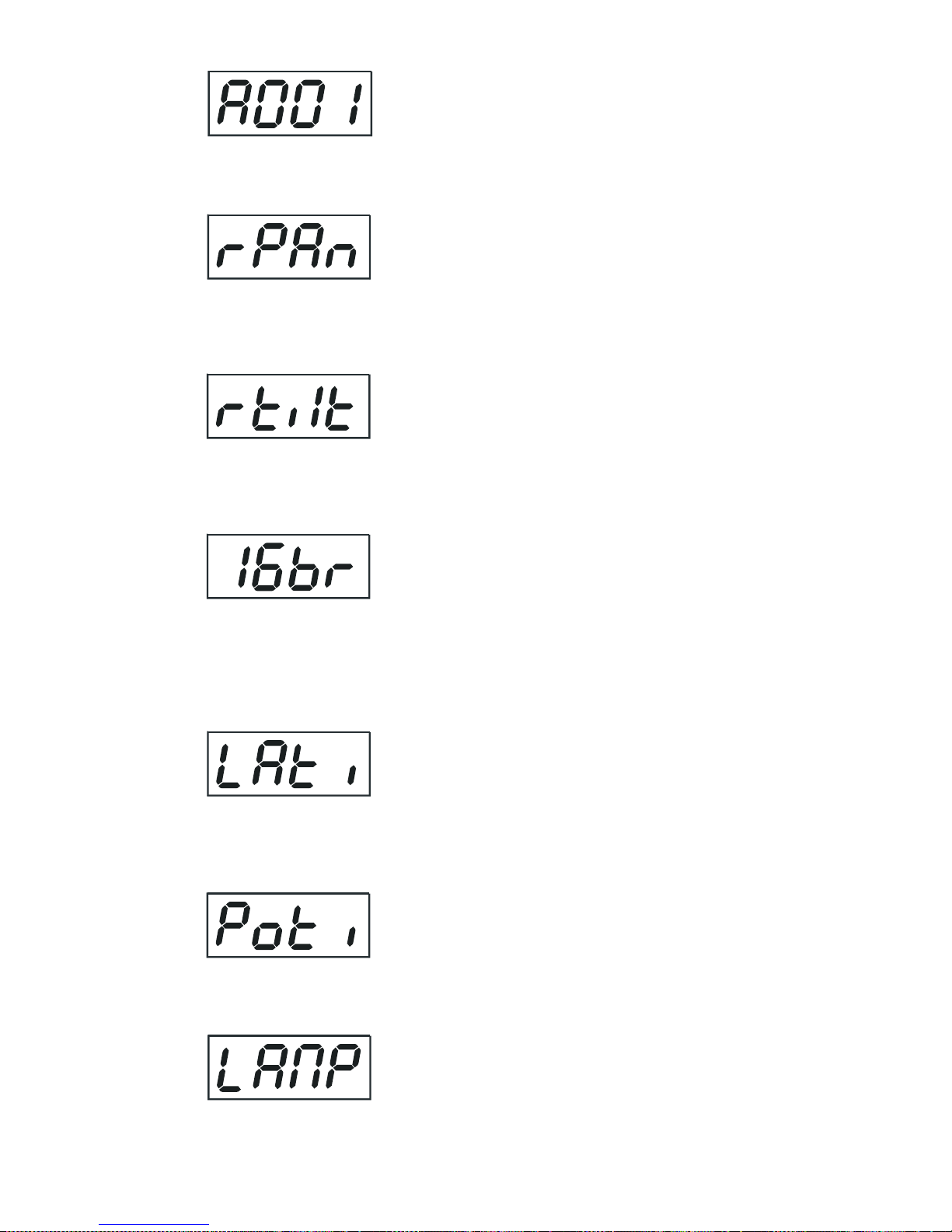
8.1 Main functions
The main menu is accessed by pressing the [Mode] key - press this one so man y times until the display shows
message "A001" (with actually stored address). Browse through the menu by the pressing [Up] and [Down]
keys - the display sho ws step by step these messages: A001, rPAn, rTilt, 16br , Lati, P oti, LAMP, dEMo, rESE,
SPEC. Press [Enter] if you wish to select one of them. The functions are described in the foll owing sections and
the function hierarchy is shown below.
Page 16
16
DMX 512 Address settings
The letter "A" flashes. Use the [Up] and [down] keys to select required address (001 - 497) and press [Enter] to
confirm or [Mode] to cancel and return to the main menu.
Pan reverse
This function allows you to inv ert the pan movement. Use the [Up] and [Down] k e ys to select "On" if y ou wish
this feature or "Off" if you don’t wish this f eature and press [Enter] to confirm or [Mode] to cancel and return to
the main menu.
Tilt reverse
This function allows you to inv ert the tilt movement. Use the [Up] and [Down] ke ys to select "On" if you wish this
feature or "Off" if you don’t wish this f eature and press [Enter] to confirm or [Mode] to cancel and return to the
main menu.
Movement resolution
By this function you can adjust the desired movement resolution 8 or 16 bit. Use the [Up] and [Down] keys to
select "On" if you wish the 16 bit high resolution or "Off" if you wish only 8 bit resolution and press [Enter] to
confirm or [Mode] to cancel and return to the main menu.
Note: If you adjust the 16 bit resolution , the fixture will occup y 16 DMX channels, if y ou adjust the 8 bit resolution,
the fixture will be operated by only 14 DMX channels. Please, check the DMX protocol.
Lamp On time
This option enables you to read the total number of hours that the lamp has been po wered On. Press [Enter] or
[Mode] to return to the main menu. In order to reset the counter to 0, you have to hold the [Up] and [Down]-
button and press the [Enter]-button.
Power On time
By this option you can read the total number of hours that the ServoSpot 575 has been powered On. Press
[Enter] or [Mode] to return to the main menu.
Switch On/Off the lamp
Use the [Up] and [Down] ke ys to select "On" if you wish the s witch On the lamp or "Off" if you wis h s witch Off
the lamp and press [Enter] to confirm or [Mode] to cancel and return to the main menu.
Page 17
17
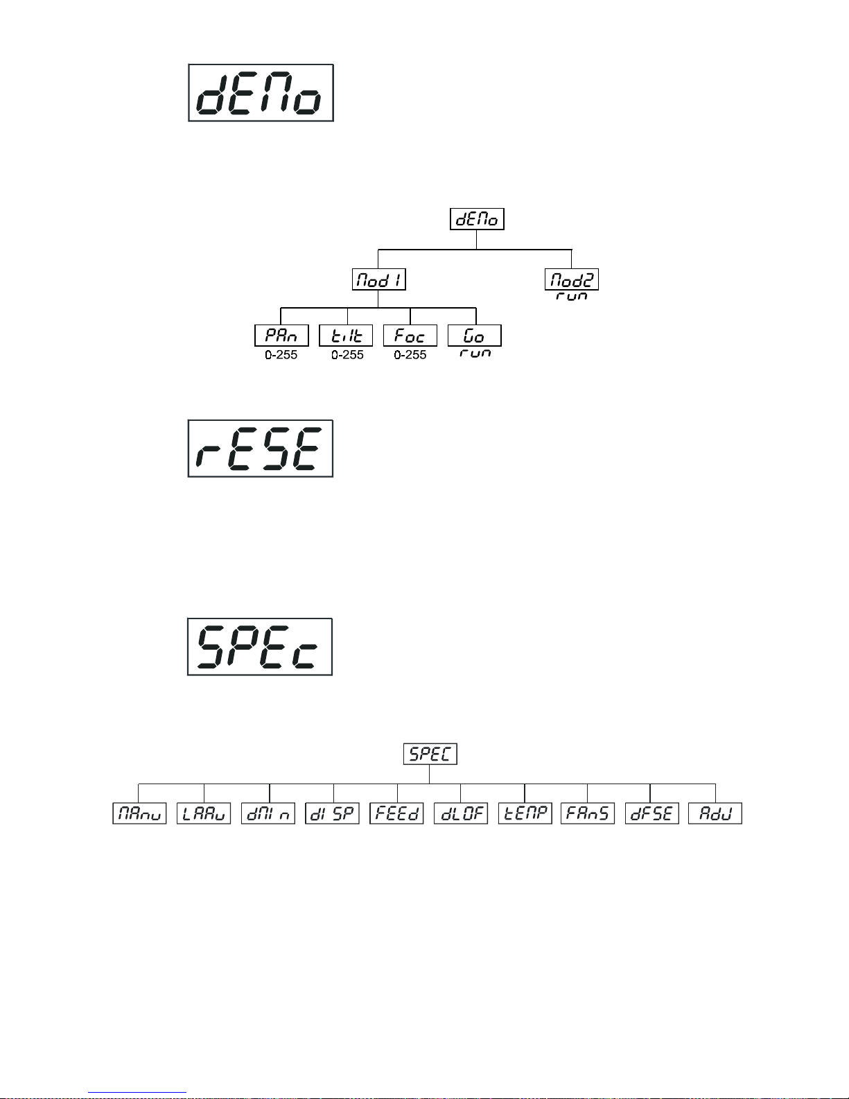
Demo sequences
This function allows you to run a special demo-test sequences without an external controller , which will show you
some possibilities of using ServoSpot 575. Press [Up] and [Down] keys to select the "Mod1" or "Mod2"
sequences. The "Mod1" is suitable for projections on the wall, ceiling or ground without any head-movement,
the "Mod2" uses all ServoSpot 575 functions and therefore is good for a complete introduction of the fixture.
Reset Function
Press [Enter] key to run reset. This option enab les the ServoSpot 575 to index all eff ects (functions) and return
to their standard positions.
8.2 SPEC - Special functions
Use the [Up] and [Down] ke ys to browse through the special functions and select the one by pressing [Enter].
Page 18
18
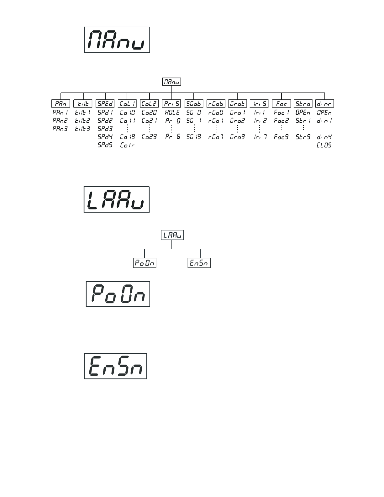
Manual control of effects
This function allows you to control manually the channel functions of the fixture. Use the [Up] and [Down] keys
to select desired function and press [Enter] to adjust the effect or [Mode] to cancel and return to the menu.
Lamp On automatically
This menu allows you to turn the lamp On after switching the fixture On and s witch On/Off the lamp light sensor.
Lamp On after switching the fixture On
This function enables to turn the lamp On automatically after switching the fixture On. Use the
[Up] and [Down] keys to select "On" if y ou wish to turn the lamp On automatically after switching
the fixture On or "Off" if you wish the lamp Off after switching On the fixture and press [Enter] to
confirm or [Mode] to cancel and return to the menu.
Switch On/Off the lamp light sensor
Use the [Up] and [Down] keys to select "On" if you wish to switch the lamp light sensor On and
press [Enter] to confirm or [Mode] to cancel and return to the menu.The option"On" is for the
standard operation.
Use the [Up] and [Down] keys to select "Off" if y ou wish to s witch the lamp light sensor Off and
press [Enter] to confirm or [Mode] to cancel and return to the menu.
Important: The option"Off" is for "emergency operation" only if the lamp light sensor is def ective and
you will wait for a delivery of the spare light sensor! If the lamp light sensor was switched Off,the error
messages "LAEr,SnEr,HEAt" will not appear on the display (only the message "HEAt" will appear if the lamp
was turned Off and On within 5 minutes ) and at switching On of the lamp the electronics will still try to ignite the
lamp until it shines (even when the lamp is damaged or absent), on this account some electronics parts could be
damaged!
Page 19
19
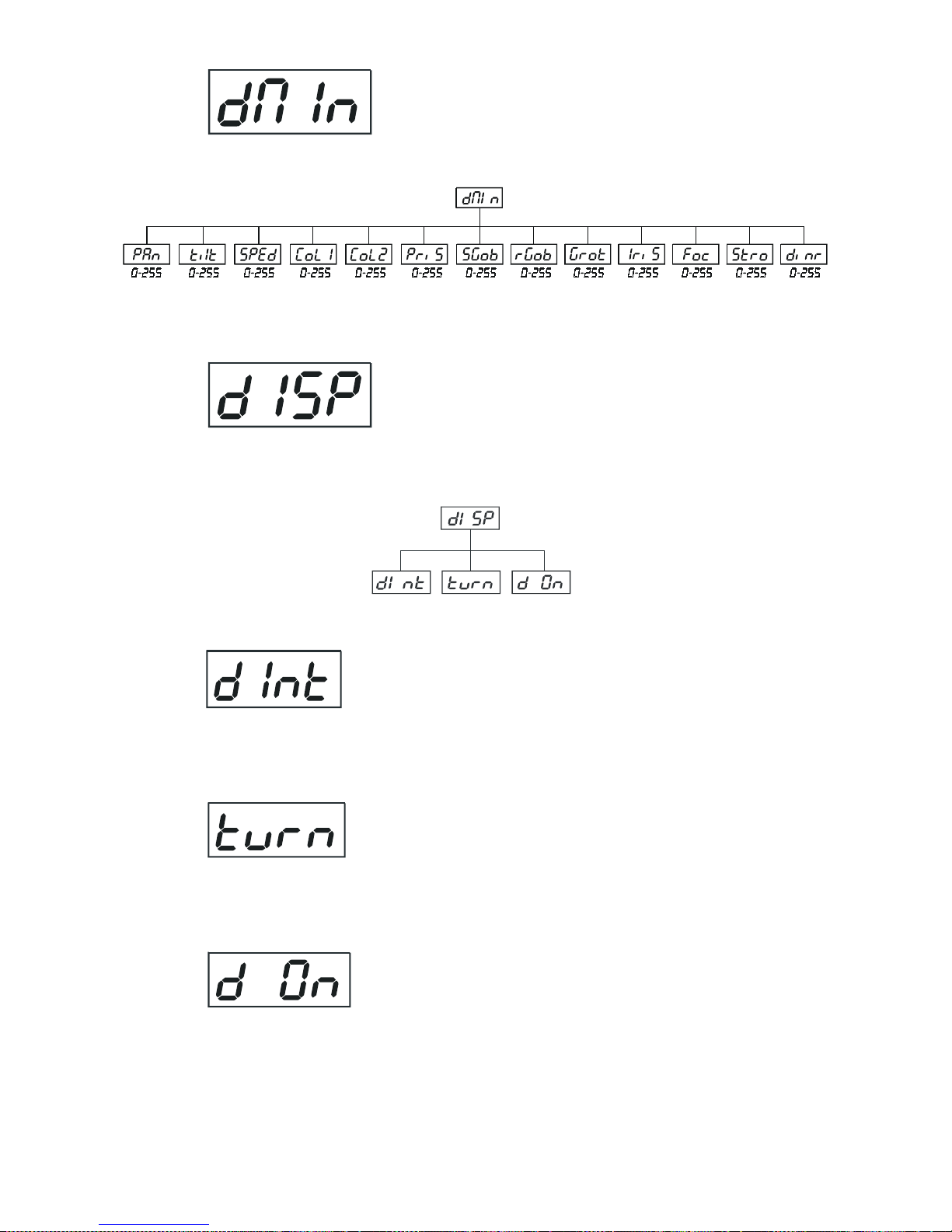
DMX values
Readout DMX values of each channel received b y the fixture . Use the [Up] and [Down] ke ys to select desired
channel and press [Enter] to read its value coming to the fixture or [Mode] to cancel and return to the menu.
Display adjusting
This function allows you to adjust the display settings:
Display intensity
By this function you can adjust from 20% to 100% the display intensity . Use the [Up] and [Down]
keys to select the lev el of the display intensity and press [Enter] to confirm or [Mode] to cancel and
return to the menu.
Display-reverse
With this function, you can rotate the display by 180°. Use the [Up] and [Down] keys to select
"normal display" or "display turned by 180°" and press [Enter] to confirm or [Mode] to cancel
and return to the menu.
Display- On
This function allows you to keep the display On or to turn Off automatically 2 minutes after last
pressing any key on the control board. Use the [Up] and [Down] keys to select "On" if y ou wish to
keep the display On or "Off" if you wish to turn Off automatically 2 minutes after last pressing any
key on the control board and press [Enter] to confirm or [Mode] to cancel and return to the menu.
Page 20
20
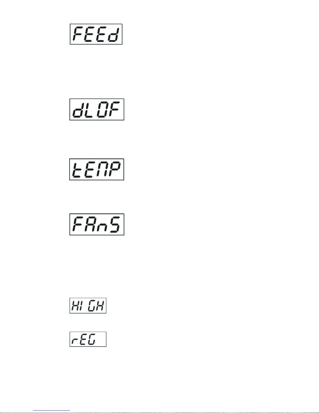
PAN/TILT feedback
This function allows to return the mowing head to the required position after changing the position by external
force (e.g.by strok e) . Use the [Up] and [Down] keys to select "On" if you wish to anab le this function or "Off"
if you wish not to return the mowing head to the required position and press [Enter] to confirm or [Mode] to
cancel and return to the menu.
Note: If the feedback was switched Off , the pan/tilt position is changed by external force and the feedbeck is
switched On again, the moving head might not to be synchronized with the DMX signal .Y ou ha ve to make a reset
in order to synchronize the moving head with the DMX signal.
Lamp Off via DMX
This function allows you to switch Off the lamp by DMX. Use the [Up] and [Down] keys to select "On" if you
want to switch Off the lamp b y DMX or "Off" if y ou don’t want to s witch Off the lamp by DMX and press [Enter]
to confirm or [Mode] to cancel and return to the menu.
Temperature
T emperature readouts of the fixture inside in Celsius . Inside temper atures below 80° C are not critical. 80° C and
more lead to the lamp being switched off. Please note that the outside temperature should not exceed 40° C .
Low fan speed operating
By using this function you can choose 5 types of low fan speed operating. Browse through this menu by the
pressing [Up] and [Down] keys - the display shows step by step these messages: "Auto,HIGH, reG, LoOF,
LoHI". Press [Enter] if you wish to select one of them or [Mode] to cancel and return to the menu.
high (max.) speed of fans
The cooling fans work on max. speed (max. coo ling)
continuous controlling of the fan speed
the fan automatically raises its speed in order to control inside temperature of the lighting, if the
temperature inside increases about certain level (the low fan speed reduces the cooling of the
lighting).This cycle can repeat several times until the temperature inside is on suitab le le v el.
Page 21
21
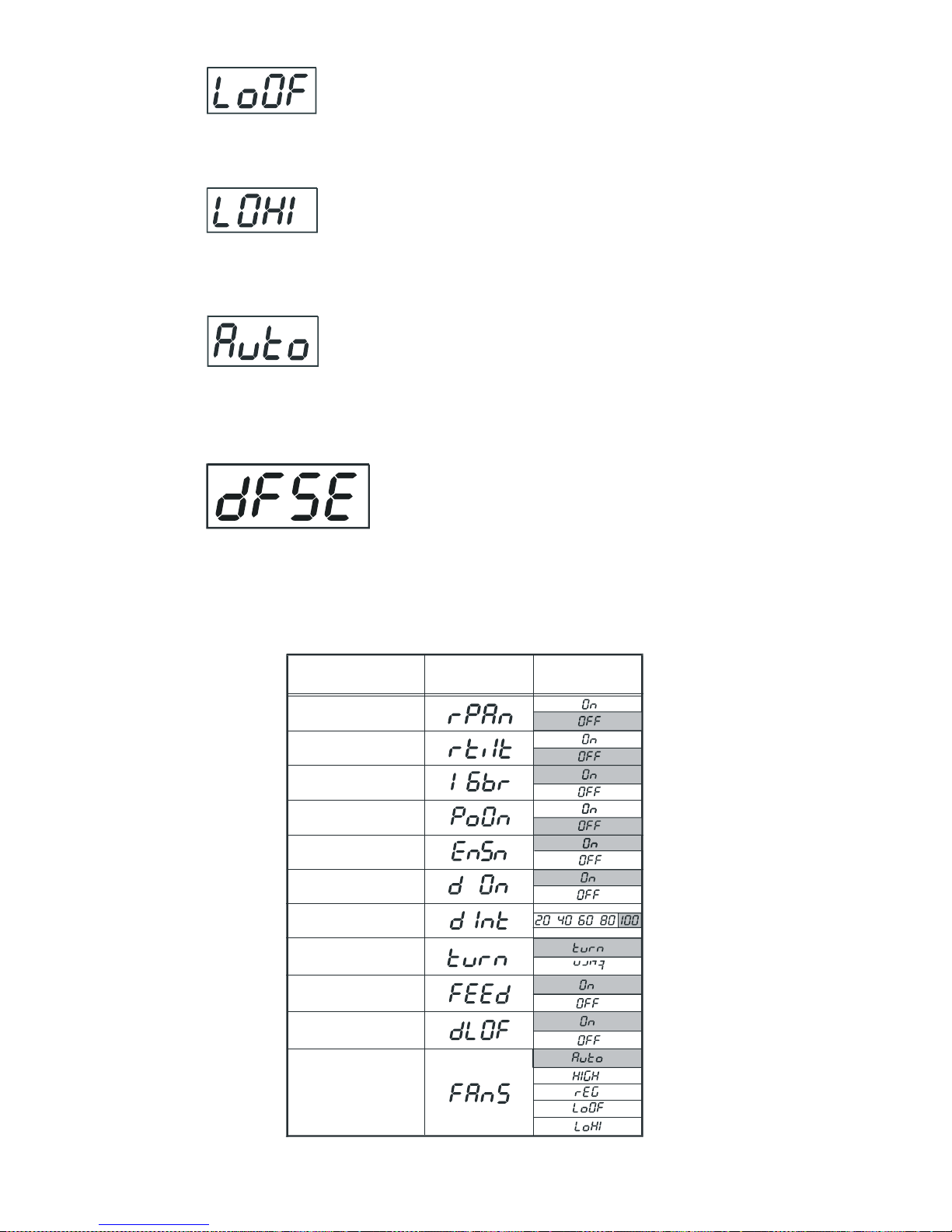
low speed/Switch Off the lamp operating
the fan keeps the adjusted low speed until the temperature exceeds max. inside temperature of the
fixture, then the ServoSpot 575 automatically switch Off the lamp.
low/high speed of the fan operating
the fan keeps the adjusted low speed until the temperature exceeds max. inside temperature of the
fixture, then the ServoSpot 575 automatically switch from low to high the fan speed.
continuous controlling of the fan speed without the DMX value
This mode is similar to "reG", but the initial lev el of f an speed can´t be adjusted b y the DMX.
Default settings
Press [Enter] to reset all fixture personalities (not the adjusting functions) to the default values. On the display
will appear "rSt" meaning that the fixture makes the reset. See the table of personality setting and their default
positions.
Perso nal ity Di sp lay Default values
(SHADED)
Pan rev erse
Tilt reverse
Movement resolution
Lamp On after switch.
the fixture On
Display intensity
Display- rev erse
PAN/TILT feedback
Lamp Off via DMX
Low fan speed
operating
Display-On
Switch On/Off
the lamp light sensor
Page 22
22
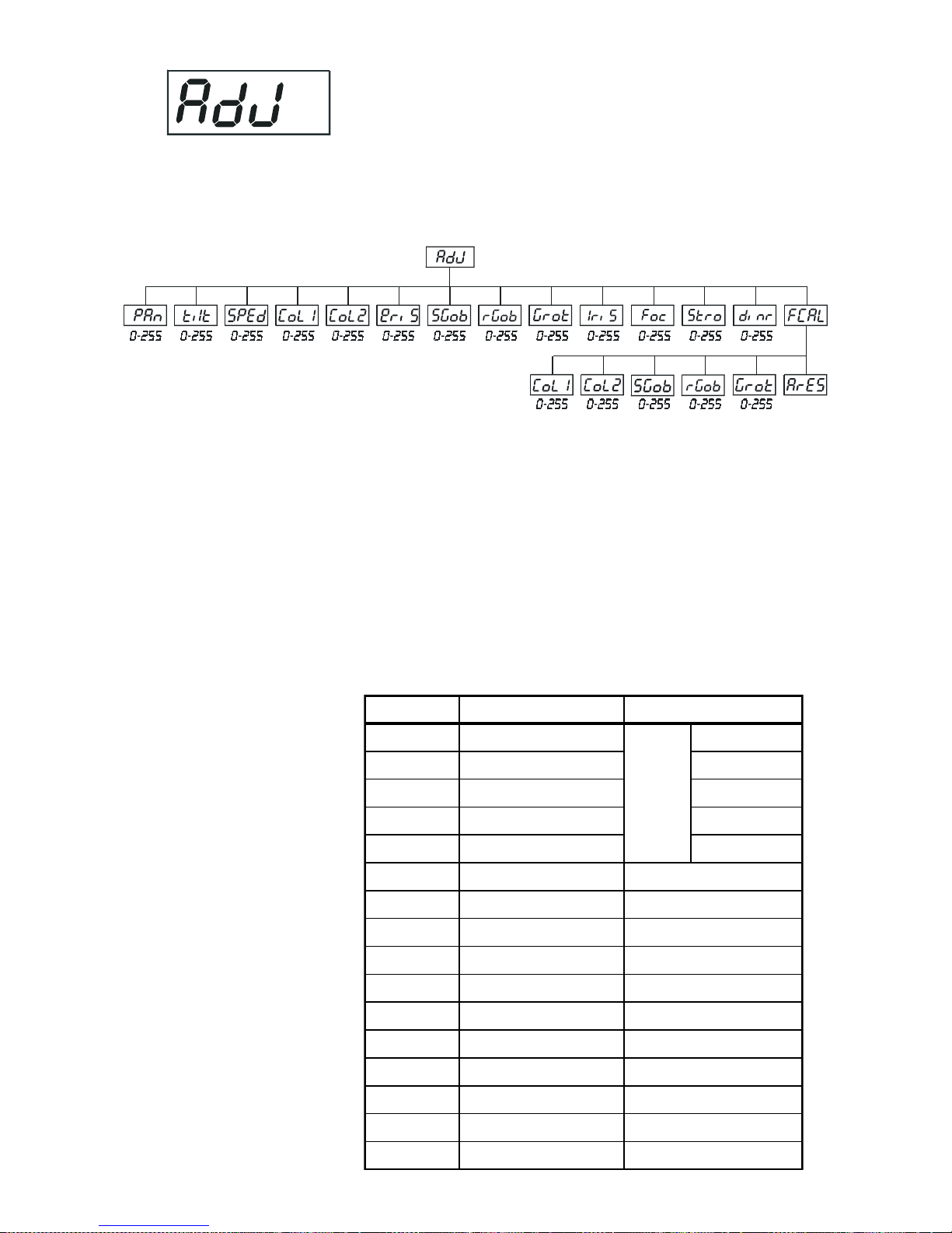
Adjusting the default positions of colour, gobo and effect wheels
By this function you can calibrate and adjust the colour and gobo wheels to their standard/right positions. Use the
[Up] and [Down] keys to browse through the adjusting menu - the display shows step by step these messages:
"P An, Tilt, SPEd, Col1, Col2, PriS, SGob, rGob, Grot, IriS, Foc, Stro, dimr , FC AL" by which you can adjust the
fixture to the required/desired position (0-255) before the function calibration. Then when the positioning is finished
use the last "FCAL" function (Fixture calibration).
1. Calibration via the control board
Press [Enter] and the [Up] and [Down] keys in order to display the following messages: "Col1, Col2, SGob,
rGob,Grot" for very smooth function calibration. Select one of them, press [Enter] and use the [Up] and [Down]
keys in order to adjust their right value from 0 to 255. Then pre ss [Enter] to confirm or [Mode] to cancel and return
to the menu. This can be repeated for each calibration parameter if it is required. When the calibr ation is finished,
it is necessary to use the "ArES" function in order to write the calibration values to the memory (EPROM) and to
make a reset in order to check the newly adjusted positions of the colour and gobo wheels . When the reset of the
fixture is finished, the display will show the "FCAL" message. Press [Enter] to repeat the calibration or [Mode] to
return to the "AdJ" menu.
2. Calibration via the external controller
Press [Enter] and the [Up] and [Down] keys in order to display the following messages: "Col1,Col2,SGob,
rGob, Grot" - calibration parameters. Select one of them and press [Enter].
Now you can calibrate the colour 1,colour 2, static gobo and rotating gobo wheels b y y our controller. The DMX
calibration protocol is described in the table.
DMX Calibration protocol:
DMX chanel
Function
1
Colour 1
Calibration 0-255
2
Colour 2
Calibration 0-255
3
Static gobo
Calibration 0-255
4
Rotating gobo
Calibration 0-255
5
Gobo rotating
Calibration 0-255
6
No function
7
Colours 1
8
Colours 2
9
Prism
10
Static gobos
11
Rotating gobos
12
Gobo rotation
13
Iris14Focus
15
Strobe
16
Dimmer
Smoothmicrostepmovement
Standard protocol
Standard protocol
Standard protocol
Standard protocol
Standard protocol
Standard protocol
Standard protocol
Standard protocol
Standard protocol
Standard protocol
Page 23

23
After having calibrated required functions press [Enter] to confirm (or [Mode] to cancel and return to the menu
without reset by the "ArES" function) and use the "ArES" function in order to write the calibration values to the
memory (EEPROM) and to make a reset in order to check the new adjusted positions of the colour 1, colour
2,static gobo and rot.gobo wheel and gobo indexing.
9. Error and information messages
HEAt
This message appears if you try to switch on the lamp within 5 minutes after having switched it off (the
lamp is too hot). The message will appear on the display if the lamp doesn't ignite within 28 seconds. The
ServoSpot 575 will store this information and automatically ignite the lamp when the 5 minutes period has expired.
Caution: The message is disabled if the lamp light sensor (function "EnSn") is switched Off (only if the
lamp was turned Off and On within 5 minutes,the message "HEAt" will appear).
LAEr
The ignition of the lamp is seven times unsuccessful (the HEAt message appeared six times before), and
the display shows "
LAEr
", meaning that the lamp could be damaged or even missed, the fixture is overheating
(this can occur if the ambient temperature is 40° C or more) or there could be a failure on the ignitor or ballast.
Please place or replace the lamp, check the ambient temperature or contact your dealer if the situation was not
caused by the lamp.
Caution:The message is disabled if the lamp light sensor (function "EnSn") is switched Off.
FAn
The message informs you that the fixture was ov erheating and the lamp w as s witched off . This message
will appear on the display if the fan speed operating "LOOF" is selected.
MbEr
This messsage informs you that the main PCB does not communicate correctly with the Control Board.
CIEr
(color-wheel 1 error)
This messsage will appear after the reset of the fixture if the magnetic-indexing circuit malfunctions (sensor failed or magnet missing) or the stepping-motor is defectiv e (or its driver circuit on the main PCB). The colorwheel is not located in the default position after the reset.
C2Er
(color-wheel 2 error)
This messsage will appear after the reset of the fixture if the magnetic-indexing circuit malfunctions (sensor failed or magnet missing) or the stepping-motor is defectiv e (or its driver circuit on the main PCB). The colorwheel is not located in the default position after the reset.
rGEr
(rotating gobo-wheel error)
This message will appear after the reset of the fixture if the magnetic-indexing circuit malfunctions (sensor fai led
or magnet missing) or the stepping-motor is defective (or its driver circuit on the main PCB). The rotating gobowheel is not located in the default position after the reset.
IGEr
(rotating gobo indexing error)
This message will appear after the reset of the fixture and if the magnetic-indexing circuit malfunctions
(sensor failed or magnet missing) or the stepping-motor is defective (or its driv er circuit on the main PCB). The
rotating gobo is not located in the default position after the reset.
SGEr
(static gobo-wheel error)
This message will appear after the reset of the fixture if the magnetic-indexing circuit malfunctions (sensor
failed or magnet missing) or the stepping-motor is defective (or its driver circuit on the main PCB). The static
gobo-wheel is not located in the default position after the reset.
PrEr
(prism error)
This message will appear after the reset of the fixture if the magnetic-indexing circuit malfunctions (sensor
failed or magnet missing) or the stepping-motor is defective (or its driver circuit on the main PCB). The prismwheel is not located in the default position after the reset.
FtEr
The message informs you that the fixture was overheating (occured if the ambient temperature is40° C or
more) and that the relay switched off the lamp . This message will appear on the displa y until the temperature will
be on a suitable level, then the display will show the HEAt message meaning the lamp is too hot.
Page 24
24
SnEr
This message appears if the lamp lighting sensor is failed. Please, contact your dealer.
Caution: The message is disabled if the lamp light sensor (function "EnSn") is switched Off.
PoEr
This message will appear if the fixture was shortly disconnect from the main.
PAEr
(PAN-yoke movement error)
This message will appear after the reset of the fixture if the yoke’ s magnetic-inde xing circuits malfunction
(sensors failed or magnet missing) or the stepping motor is defective. (Or its driving IC on the main PCB). The
yoke is not located in the default position after the reset.
tiEr
(TILT-head movement error)
This message will appear after the reset of the fixture if the head’ s magnetic-indexing circuit malfunctions
(sensor failed or magnet missing) or the stepping motor is defective. (Or its driving IC on the main PCB). The
head is not located in the default position after the reset.
FrEr
It will appear if the frequency of the mains is not standard 50 or 60Hz.
10. Technical specifications
Power supply:
EU-model:........................208/230/240V AC, 50/60Hz ~
Fuse:...............................T 5.0A@ 230V
US-model:........................100/115/208/230V AC, 50/60Hz ~
Fuse:................................T 10A@115V
Pow er consumption:..........900 VA
Lamp:
-OSRAM HSR 575/2 95V/575W GX-9,5 750h ; PHILIPS MSR 575/2 95V/575W GX-9,5 750h or
MSD 575 95V/575W GX-9,5 2000h
Optical System:
- High luminous-efficiency parabolic reflector , focus lens and m ultistep z oom lenses
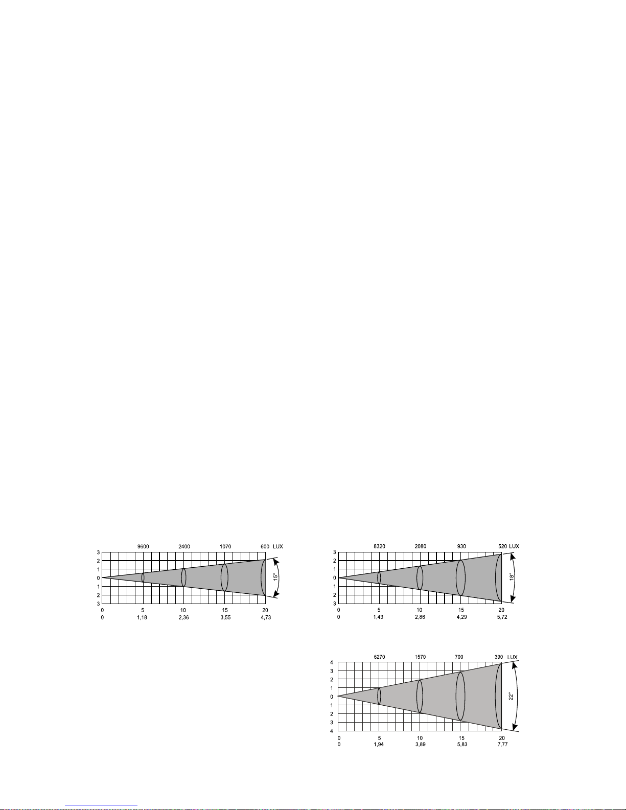
system(15°,18°,22° beam angles)
- All lenses are anti-reflection coated
Beampath:
Beam angle 22°
Beam opening (m)
Beam opening (m)
Beam opening (m)
Distance (m)
Diameter (m)
Distance (m)
Diameter (m)
Distance (m)
Diameter (m)
Beam angle 15° Beam angle 18°
Page 25

25
Colours:
Colour wheel 1:
- 9 dichroic colour-filters plus white,colour-wheel with variable rotation speed in both directions
Colour wheel 2:
- 6 dichroic-colour filters,colour temperature filters 3200 K and 5600 K,UV filter plus white
Static gobos:
- 9 static metal-gobos plus an open position
- static gobo wheel cont. rotation
Rotating gobos:
- 6 interchanged gobos plus an open position:3 metal gobos, 1 glass gobo and 2 dichroic gobos
rotating in both directions at different speeds
- Gobo indexing
- Rotating gobo-wheel cont. rotation
- Outside diameter 27 mm, image diameter 23 mm.
Strobe:
- Strobe effect with variable speed (1 - 10 flashes per second)
Dimmer:
- Smooth dimmer from 0 - 100 %
Prism:
- 3-facet-prism rotating in both directions at different speeds
Focus:
- Remotely controllable via DMX
- Motorized multi-step-zoom with three different apertures (15°,18°,22° )
Iris:
- Motorized (steplessly adjustable) iris for different beam diameters
Effects:
- 16 prism-gobo macros
- 9 static shacking gobos with variable speed
- preprogrammed variable iris pulse effects
Motors:
- 16 high quality stepping-motors controlled by microprocessors
Electronics:
-Addressing,special functions setting,effects calibration via control panel with 4-digit LED display
-Readout fixture and lamp usage,receiving DMX values,temperature, etc
-Built-in analyzer for easy fault finding,error messages
-Remotely switching of the lamp
-Bilt-in demo sequences
-Black-out while head moving or gobo/color changing
-Silent fans cooling,remotely controllable speed of fans
-Self-resetable thermo-fuse
-Digital serial input DMX-512
-16 control-channels (full 16 bit protocol):
Channel 1: Horizontal head-movement 8 bit
Channel 2: Fine Horizontal head-movement 16 bit
Channel 3:V ertical head-movement 8 bit
Channel 4: Fine V ertical head-movement 16 bit
Channel 5: P an/Tilt speed
Channel 6: F an speed, On/Off lamp, reset
Channel 7: Colours 1
Channel 8: Colours 2
Channel 9: Prism rotation control,Prism/Gobo macros
Channel 10: Static gobos
Page 26
26
Channel 11: Rotating gobos
Channel 12: Gobo rotation, gobo indexing
Channel 13: Iris
Channel 14: Focus,multistep zoom
Channel 15: Shutter, strobe
Channel 16: Dimmer
Pan/Tilt:
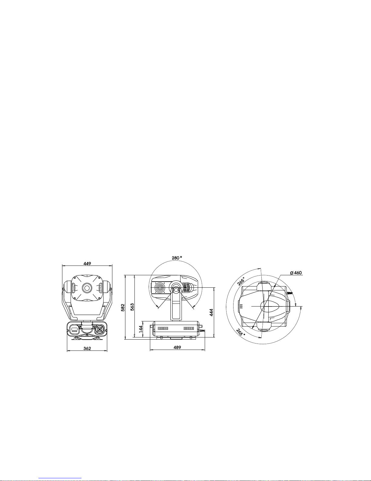
-Pan movement r ange 530°
-Tilt movement range 280°
-8/16 bit movement resolution
-Automatic Pan / Tilt position correction
-Maximum P AN-mo vement 530° in 2.65 s
-Maximum TILT-movement 280° in 1.68 s
Rigging:
-Stands directly on the floor
-Mounts horizontally or vertically with 2 clamps
-2 truss orientation
-Safety chain/cord attachment bolt
T emperatures:
-Maximum ambient temperature
t
a
: 40° C
-Maximum housing temperature
t
B
(steady state): 80° C
Dimensions and weight:
-Length of base (including handles): 467 mm
-Width of yoke: 449 mm
-Height (head horizontal): 582 mm
-Weight (net): 33 kg
-Shipping weight: 38 kg
Page 27

27
11. Maintenance and cleaning
It is absolutely essential that the fixture is kept clean and that dust, dirt and smoke-fluid residues must not build
up on or within the fixture. Otherwise, the fixture‘s light-output will be significantly reduced. Regular cleaning will
not only ensure the maximum light-output, but will also allow the fixture to function reliably throughout its life.
A soft lint-free cloth moistened with any good glass cleaning fluid is recommended, under no circumstances
should alcohol or solvents be used!
DANGER !
Disconnect from the mains before starting any
maintenance work
The objective lens will require weekly cleaning as smoke-fluid tends to building up residues, reducing the lightoutput very quickly . The cooling-fans should be cleaned monthly.
The gobos may be cleaned with a soft brush. The interior of the fixture should be cleaned at least annually u sing
a vacuum-cleaner or an air-jet.
The dichroic colour-filters, the gobo-wheel and the internal lenses should be cleaned monthly.
T o ensure a proper function of the gobo-wheel, we recommend lubrication in six month intervals. The quantity of
oil must not be excessive in order to avoid that oil runs out when the gobo-wheel rotates.
Replacing the fuse
If the lamp burns out, the fine-wire fuse of the device might fuse, too . Only replace the fuse b y a fuse of same type
and rating.
Before replacing the fuse, unplug mains lead.
Procedure:
1) Unscrew the fuseholder on the rear panel with a fitting screwdriver from the housing (anti-clockwise).
2) Remove the old fuse from the fuseholder .
3) Install the new fuse in the fuseholder .
4) Replace the fuseholder in the housing and fix it.
12. Appendix
We believ e y ou will enjo y y our ServoSpot 575. W e assure you will enjoy this product for years if you f ollow the
instructions given in this manual.
If you have any questions and comments, please do not hesitate to contact us.
Please note: errors and omissions for every information given in this manual excepted. Every information is
subject to change without prior notice. Any claim due to missing or wrong information in this manual is herewith
excluded!
 Loading...