

Page 1
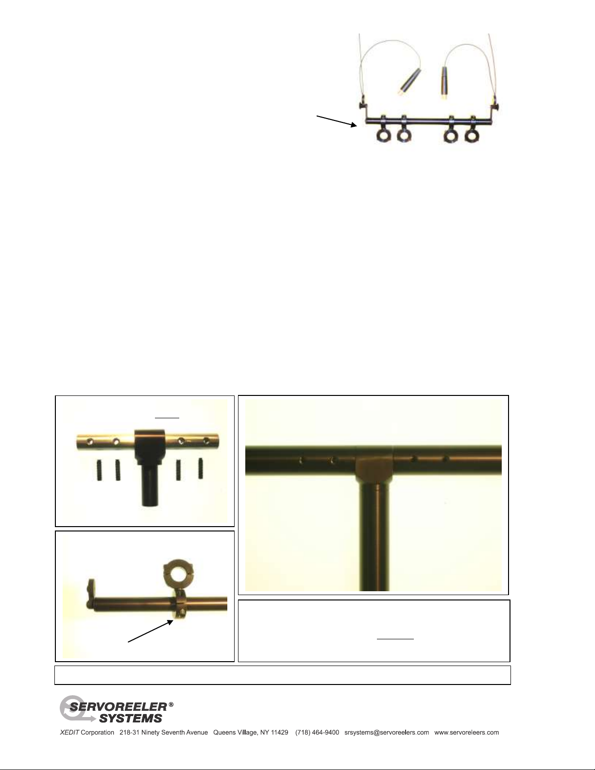
Trapeze Decca Tree
The Central “T” fitting - showing the threaded
holes and nylon tipped set screws.
The Assembled SRS-Decca Tree central section showing the four
securing set screw holes. This basic “T” formation is the heart of
the (2m x 1.5m) Decca Tree Array configuration.
The CP-1 cable clamp end of the 1m section
One of the universal microphone brackets
This stable microphone platform can support several microphones.
The three Servoreelers® supporting each leg of the SRS-Decca-Tree can
be configured with two or four-conductor cable, enabling them to feed
three or more microphone positions. CAUTION This is an assembly that
is used overhead and the assurance of a proper and safe installation is the
responsibility of the installer and or the user.
Please contact us should you have any questions about the safe installation of this product. [email protected]
Standard Trapeze with
four Universal Clamps
Set-Up Instructions
Servoreeler® Systems is offering its version of the industry standard Decca Tree microphone platform.
The Decca Tree was first developed in the early 1950s at Decca records. This microphone array was originally
supported on a tall boom or stand. Having produced a number of its Trapeze microphone bars and multi-microphone
array platforms, Servoreeler® Systems has now designed a Decca Tree platform employing the original 2m x 1.5m
configuration. This SRS-DECCA TREE employs the same light weight tubular components as pictured above. It
employs our CP-1 non-marring 2mm cable clamps and our universal microphone brackets. The entire assembly can
be “flown” by three Servoreelers® – each supporting one of the three ends through a CP-1 2mm cable clamp. This
provides the possibility of remote control positioning of the entire Decca Tree microphone array.
The SRS Decca Tree relies on a precision central “T” fitting to which the three tubular members are securely joined.
The main 1.5m section has the “T” fitting permanently attached to one end. The solid connecting “pin” installed in this
fitting has four tapped holes, two on each extension. These are designed to accept each of the two 1m sections. The
1m tubular sections have two matching clearance holes to align with the tapped holes. The four 8-32” Allen set
screws have a soft nylon tip. After sliding the 1m sections onto the central pin, align the clearance hole with the
tapped hole; then, carefully start engaging the set screws with the nylon tip facing into the threaded holes. Be careful
not to force the start of the screw engagement to avoid cross-threading the steel screw into the aluminum pin. Notice
that the clearance holes in the 1m sections do not go through to the other side of the tubing. It is this other inside tube
wall that the set screw will tighten against. Tighten set screws slightly past initial inside contact, just enough to allow
the nylon tips to conform to the inner wall - while applying pressure of the tubular section towards the central T fitting
to eliminate any play. Once tightened, the heads of the screws will still extend into and be securely retained by the
holes in the1m sections. This will be form a very stable 2m long assembly with a 1.5m central extension arm.
Please refer to the accompanying Trapeze Bar instructions for the installation of the CP-1 2mm cable clamps.
 Loading...