

Page 1
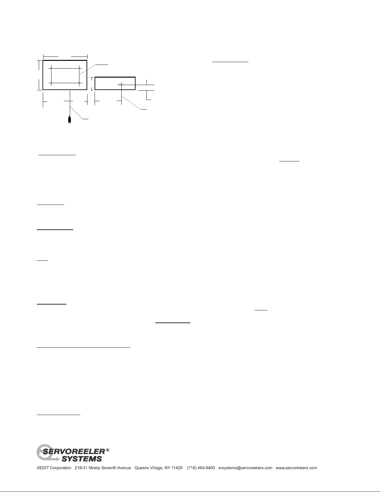
1.062" for 2mm
rear surface
cable exit point
RJ-45 Pin Out
1- Down Sense
2- Down Control
3- Common
4- + 24 VDC
5- + 24 VDC
6- Common
7- Up Control
8- Up Sense
bot.
front
Patern on the rear frame surface.
Cable exit point
2mm dia. Kevlar, Shielded Cable
D
L
H
Housing Dimensions: H = 13.25" L = 16" D = 2.60"
1/4-20 Threaded Mounting Holes
4 plcs on 9"H x 15"L Centered -
11.00"
11.00"
CAUTION: Test mounting screws by hand before tightening, -
threaded holes in aluminum frame are easily damaged.
5.0"
Distance from rear
1.312" for 6mm(.25")
SRL-90 Servoreeler
Installation and Operation
®
TEST RUNNING: We strongly urge you to test run these devices prior to installation. CAUTION ! This Servoreeler
designed to operate in a vertical orientation, with the cable exit point facing down. In addition, a minimum
payload weight of aproximately two (2) ounces is required for proper down feeding of the cable. Should the reeler be
operated in a horizontal orientation, too lightly loaded or with its cable impeded from down feeding freely; an internal
spill sensor will stop the reeler. This sensor interlock is designed to prevent internal cable accumulation and jamming.
Please note that this is a back-up system, conditions causing its intervention should be avoided. Normally this
condition is not encountered after permanent installation.
MOUNTING: The SRL-90 is provided with (4) ¼-20 threaded holes on a 9” x 15” grid on its rear surface. Prior to
installing try the machine screws by hand to assure a proper fit. Screw length should be selected so that no more than
a nominal one inch extends into the rear plate. The SRL-90 weighs Twenty One pounds all of these mounting holes
should be utilized to achieve a stable and safe mounting of the mechanism.
C A U T I O N Professional care and judgement must be exercised when mounting equipment overhead.
Mounting screws must engage a permanent, solid structural member or a metal bracket that is in turn securely attached
to such a structure. Should mounting against a wood beam or surface be required, screws of adequate size may be
employed from the inside, through the threaded holes into a load bearing structure; loosen the four cover screws about
two turns and slip the cover up from the body of the reeler. Note, when mounting against a wood surface, all four holes
must be used. Install washers as shims if required so that the center of the reeler frame is elevated clear of any
irregularities or high spots on the mounting surface.
Please note, the installer and the purchaser must assure that these devices do not pose a hazard to others,
both during and after installation. Architectural or engineering guidance is highly recommended to help assure
a safe installation that is consistent with the particular physical requirements of your project.
OPERATION: A linear regulated, 24 VDC source is required for system power. Common is connected to pins three (3)
and six (6); positive (+24V) is connected to pins four (4) and five (5) of the RJ-45 connector. Note: The RJ-45 is
organized in a symetrical configuration. A 180 degree error in the orientation when installing a connector will simply
result in reverse operation, i.e.; Up will be Down etc. C A U T I O N : Never apply any external voltage to the Up or
Down Sense terminals Pins 1 and 8, this may cause circuit damage. The sense outputs are utilized for remote
speed adjustment, logic Hold and remote indication of operating mode. If Cat-3 or 5 is employed, test before using !
SETTING the OPERATING STOP POINT: The IR sensor that controls the length of cable deployment is mounted on a
track and is easily adjusted by loosening a finger screw and positioning the sensor to obtain the desired stopping point.
To access this adjustment; loosen the four cover screws about two turns and slip the cover up from the body of the
reeler. To the middle left of the center of the storage reel, you will see a track with a small wire connected module. This
sensor module may be positioned as follows: The Servoreeler® is shipped from our factory set to maximum deployment;
with this sensor close to the storage reel hub. To reset, loosen the locking thumbscrew just enough to enable the sensor
to be moved. Positioning towards the rim of the reel will decrease payout length. Slide and tighten the sensor module to
re-locate the sensor to a new position. Activate the down mode to test the new stop point; repeat until desired length is
achieved. NOTE:This Operational stop position may be bypassed. Re-activating the down mode permits the
microphone to be lowered to a service level. Take Care that obstacles are not struck at full cable deployment!
SPECIFICATIONS: 2MM Cable capacity: 100 feet .25” Diameter - Multi-conductor Cable capacity: 34 feet
Thank you for selecting the SRL-90 Servoreeler. Should you require any assistance or have any
questions regarding its application or installation, please call our toll free line at: (800) 431-8900.
Payload: 2.2Lbs tested at 5 Lbs Weight: 21 Lbs Operating voltage: 24Vdc@1A
®
is
 Loading...