

Page 1
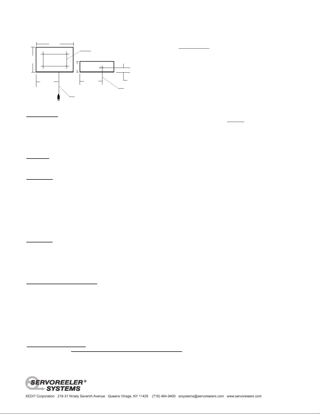
.937 (15/16)"
rear surface
cable exit point
RJ-45 Pin Out
1- Down Sense
2- Down Control
3- Common
4- + 24 VDC
5- + 24 VDC
6- Common
7- Up Control
8- Up Sense
bot.
front
mounting grid on the rear frame surface.
Cable exit point
2mm dia. Kevlar, satin black, shielded cable
D
L
H
Housing Dimensions: H = 9.25" L = 11.125" D = 2.05" 235mm x 282.6mm x 52mm
1/4-20 threaded holes in 4 places
on a 5.75"H x 10"L (14.6cm x 25.4cm)
23.8mm
5.95"
151.1mm
5.95"
151.1mm
SRL-40 Servoreeler ®
Installation and Operation
TEST RUNNING: We strongly urge you to test run these devices prior to installation. The reeler is designed for operation in a vertical
position; when test running, hold the SRL-40 in a vertical orientation with the cable exit point facing down. A minimum payload weight of
approximately two (2) ounces is required for proper down feeding of the cable. A standard XLR cable connector provides this minimum
ballast. An internal spill sensor is employed to stop the reeler if it is operated with too light a payload or with its cable impeded from
down feeding freely; This interlock is designed to prevent internal cable spill resulting in jamming the mechanism. This safety interlock
may not offer adequate protection if the unit is operated horizontally.
Please note that this interlock is a back-up system, it is prudent to avoid conditions that would overly rely on its intervention.
MOUNTING: The SRL-40 is provided with (4) ¼-20 threaded mounting holes on a 5.75” x 10” (14.6cm x 25.4cm) grid on its rear
surface. These holes are threaded to accept standard ¼-20 machine screws or other fastner. Prior to installing, try the machine screws
by hand to assure a proper fit, a faulty screw can damage the frame. Screw length should be selected so that no more than a nominal
1.0” (25.4mm) extends into the rear plate. Two or more of these mounting holes must be utilized for mounting.
C A U T I O N Professional care and judgement must be exercised when mounting equipment overhead. Mounting screws must
engage a permanent, solid structural member or a metal bracket that is in turn securely attached to such a structure. Should mounting
against a wood beam or surface be required, sheet rock or wood screws may be employed from the inside, through the threaded holes
or slots into the structure (to remove the cover, loosen the four cover screws about two turns and slip the cover up from the body of the
reeler.) Note, when mounting against a wood surface, all four holes must be used. Install washers as required so that the center of the
reeler frame is elevated clear of any irregularities or high spots on the mounting surface. This is to prevent the Servoreeler® frame
from being distorted when the mounting screws are tightened.
Please note, the installer and the purchaser must assure that these devices do not pose a hazard to others, both during and
after installation. Architectural or engineering guidance is highly recommended to help assure a safe installation, that is
consistent with the particular physical requirements of your project.
OPERATION: Servoreelers® are operated by a remotely located controller. SRC controllers provide linear regulated 24vdc system
power. Operation is initiated by either pusbutton control or through interface with an external computer control system like AMX or
Crestron. IR sensors are employed to provide empty and full limits. An adjustable operating stop is also provided. This adjustable stop
operates from the deploy mode. After this preset stop is reached, re-start with a sustained down command to reach a lower “service
level”. Automatic or incremental operation is selectable. The automatic mode provides locked-in operation that is initiated by a single
“Deploy” or “Retract” momentary signal. The incremental mode facilitates fine positioning by allowing the Servoreeler® to respond to
individual, incremental, commands. Test running as described below, should always be performed in the incremental mode.
SETTING OPERATING STOP POINT: The IR sensor that controls the length of cable deployment is mounted on an adjustable module
and track. To access this adjustment; loosen the four cover screws about two turns and slip the cover up from the body of the Reeler.
To the middle right of the cable storage reel, you will see an aluminum track with a guide slot in the middle. It is calibrated at three
relative settings: 20’ (6m), 30’ (9m) and 40’ (12m) An adjustable module is set into this slot with a thumbscrew. The Reeler is shipped
from our factory set to 30 feet (9m) of deployment. To reset, loosen the locking thumb screw just enough to enable the module to slide;
utilizing the left edge as a pointer, push on the bracket utilizing firm finger pressure to re-locate the sensor to a new position. Retract
above this point then re-activate the down mode to test the new stop point; repeat until desired length is achieved. Final positioning may
require very slight movement of this module. Gently tighten the thumbscrew to retain the setting. Excessive force is not required and
should not be used when tightening. This pre-set stop position will take place from the down mode and may be bypassed to reach a
lower service position by another sustained down command signal. CAUTION: Maximum deployment of this Servoreeler® is 45 feet;
verify that this reach does not exceed the physical height limits of your facility and permit the microphone to collide with a surface.
OPERATIONAL CAUTION: When handling the cable after installation, DO NOT pull on the cable exerting a force greater than the
normal payload weight. Never exceed 10Lbs (4.5kg) of pull on the end of the cable. Non-linear or excessive pull force of the cable will
distort the concentricity of the cable pack on the storage reel. This will adversely affect the operation of the IR sensors. Should this
occur, cable pack concentricity, can be restored by fully deploying and then retracting the microphone cable with its normal payload.
Should you require any assistance in the US, please call (800) 431-8900.
 Loading...