

Page 1
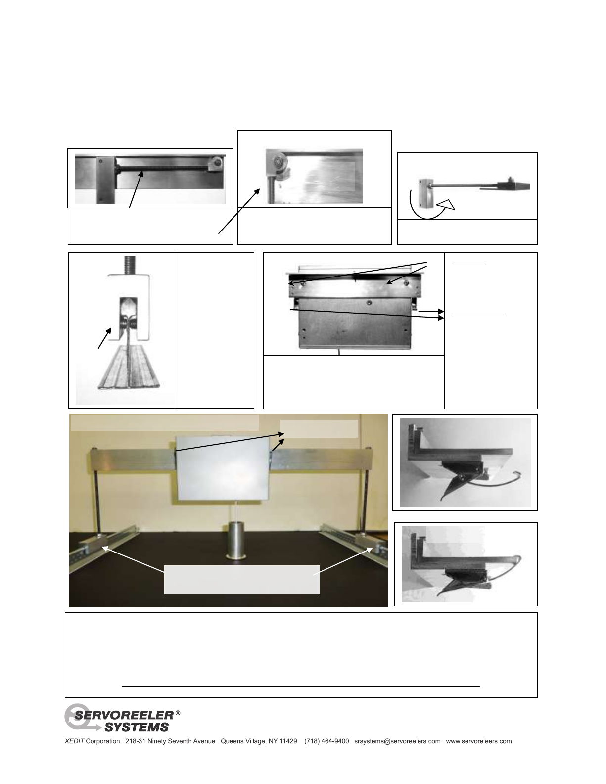
Support arm folded in its stowed position.
The next step shows the arm
extended to its installation position.
Toggle Clamps
“Inverted”
“L” beam Bridge
Ceiling Strut - Bridge support foot -
fixed in place by 10-32” set-screws
Suspended Ceiling Bridge Installation
The machined aluminum feet are positioned and secured by tightening the set screws – centering these screws so that these feet
are aligned straight onto the ceiling support truss – Engage the Servoreeler / Slide assembly onto the inverted “L” beam. The
Servoreeler Carrier bracket can then slide along the length of the inverted “L” shaped bridge to be centered on the bore of the
Bezel. When correctly aligned, secure in place by engaging the two toggle clamps on each side of the mechanism – latching to
the bottom edge of the inverted “L” bridge. When the installation is complete, insure that all fasteners are tight.
Please contact us if there are any questions with regard to this product: [email protected]
The image above illustrates the Servoreeler
mounting slide attached to a Servoreeler with
the 8-32” flat head socket screws - using the
3/32” Allen key that has been provided.
Foot support tightened to install
position.
Stop Pins
Hook over inverted “L”
beam to restrain the
Servoreeler mounting
– slide assembly.
Toggle Clamps
Slide the Servoreeler
carrier bracket to align
the microphone cable
with the center of the
bezel. To secure latch the bracket onto
the bottom of the “L”
Beam Bridge with the
toggle clamps.
Evenly
center
Allen
set screws
and
tighten.
REAR view of
the bridge rail.
Example of typical above ceiling configuration
Deploy the threaded rod support clock-
wise and tighten to position as shown.
Engage the foot
section of the
vertical bridge
support - onto the
ceiling truss.
Adjust set screws
with the 3/32” key
so that the foot is
centered on the
ceiling truss..
Toggle Clamp Open
Toggle Clamp Closed
New Product!
SCB-24 Bridge Fixture
Folding Servoreeler® Ceiling Bridge Fixture
 Loading...