

Page 1
2700
Combustion Gas Analyser
™
Please record your analyser details below
Part Number
Serial Number
Tag Number
Page 2

Blank
Page 3
2700
Series
i
Page 4

Blank
Page 5
2700 Series
ii
Page 6

Blank
Page 7
Servomex 2700 Quickstart Manual
Servomex 2700 Quickstart Manual
1
1. INTRODUCTION
1.1 Warnings, Cautions and Notes
This manual includes WARNINGS, CAUTIONS and NOTES
which provide information relating to the following:
1.2 Scope of this manual
This manual describes the operation of the Servomex 2700
Combustion Gas Analyser and details the various options that
are available.
• For the technical specification, see Section 5 of this
manual.
• For installation details, see the Installation Manual (part
no. 02700005C).
• For servicing details, see the Service Manual (part
no. 02700002C). This is written for use by suitably qualified
personnel.
• For the addresses for technical assistance and spares, see
the rear cover of this manual.
WARNINGS
Hazards which could result in personal injury or death
CAUTIONS
Hazards which could result in damage to equipment
or property
NOTES
Alert the user to pertinent facts and conditions
About this manual
Reference: 02700/003C/3
Order as part number: 02700003C
Page 8

Servomex 2700 Quickstart Manual
Servomex 2700 Quickstart Manual
2
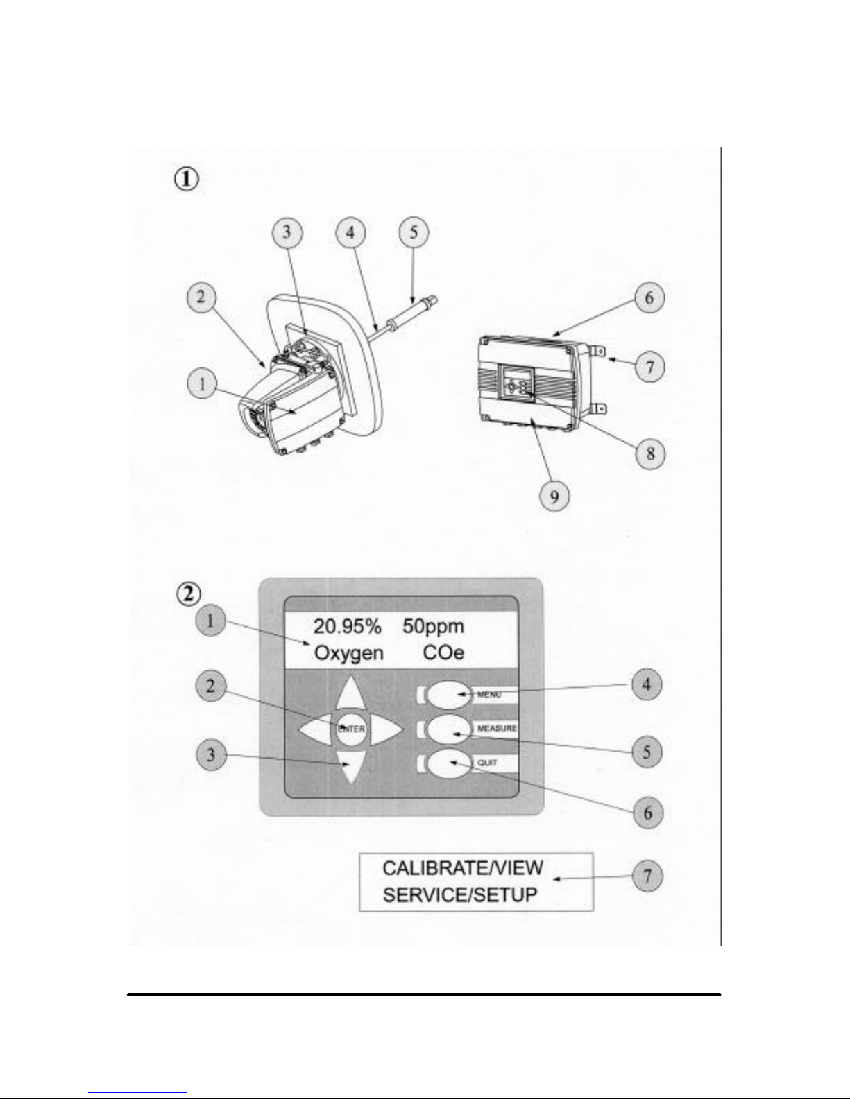
1.3 Key to Figures on inside of front cover of this manual
(Figures 3a and 3b can be found at the end of this manual)
CE Marking
The Servomex 2700 analyser carries the CE mark which
indicates conformity with the European Community
Directives on CE Marking (93/68/EEC), Electromagnetic
Compatibility (EMC 89/336/EEC) and Low Voltage Directive
(LVD 73/23/EEC).
Servomex 2700 control units are marked in conformity with
the Explosive Atmospheres (ATEX) Directive (94/9/EC)
when fitted with a European hazardous area certification
marking plate.
Figure 1 Sensor head and control unit
1 Terminal box 6 Control unit
2 Sensor head 7 Wall mounting straps
3 4" mounting flange 8 Display and keypad
4 Sample probe 9 Hinged access door
5 Sample filter
Figure 2 Control unit display and keypad layout
1 LCD with measurement display 5 MEASURE key
2 ENTER key 6 QUIT key
3 ARROW keys 7 Alternative main
menu display
4 MENU key
NOTES
As good practice it is recommended that the analyser is
checked/validated with check gas every month and then
calibrated as required. This period can be extended as a
result of operating experience.
Page 9

Servomex 2700 Quickstart Manual
Servomex 2700 Quickstart Manual
3
2. STARTUP AND SHUTDOWN
2.1 Analyser startup
If the sensor head and sample probe have been removed from
the flue, then refit the sensor head and sample probe to the flue
and reconnect any interconnecting wiring (see Installation
Manual).
Switch on the electrical power to the sensor head and to the
control unit.
Leave the unit for two hours to warm up and then check that no
faults are indicated on the control unit display screen.
Connect the aspirator air supply to the sensor head. The correct
operating pressure is stated on a label attached to the inside of
the terminal enclosure on the side of the sensor head.
If necessary, connect calibration gases to the sensor head to
verify correct operation. See Section 3.4 for Calibration
procedure.
CAUTION
If the analyser is to be installed in a low temperature
environment (-20°C) then it should be powered up for a
period of two hours before the compressed air aspirator
supply is applied. This prevents corrosive sample gases
from condensing inside the sensor head pipe work.
NOTES
• The analyser should be allowed to stabilise for several
hours (typically overnight) before calibration.
• It is then recommended that calibration gases be passed
through the sensor head to confirm operation of the
analyser.
Page 10

Servomex 2700 Quickstart Manual
Servomex 2700 Quickstart Manual
4
2.2 Analyser shutdown
Attach a dry air supply to the calibration port of the sensor head
and purge the sensor head for 5 minutes at 600 ml/min flow
rate. The aspirator air supply should be left on at this point.
Switch off the aspirator air supply to the sensor head.
Switch off the electrical supply at the control unit and then at the
sensor head.
Leave the sensor head to cool down for a minimum of two
hours.
If the analyser is to be un-powered for more than 1 week then
please note the cautions above.
WARNING
The sensor head is heated and may be attached to a hot
flue. The external surfaces will be uncomfortably hot even
after power down for several hours. Exercise care when
handling the sensor head even when un-powered on a hot
flue.
CAUTION
• The sensor head should always be powered when left on
a flue which is in use. If left un-powered, the sensor head
can suffer corrosion damage.
• If the process is out of service for a short time it is
recommended that the analyser sensor head is left
powered. It is not essential that the aspirator air is left
flowing.
• If the analyser has to be switched off for more than
1 week whilst on a flue which is in use, it is
recommended that a flow of dry air be connected to the
calibration port. Alternatively, the sensor head can be
removed from the flue and a blanking plate fitted. This will
prevent corrosive gases from entering the sensor head.
Page 11

Servomex 2700 Quickstart Manual
Servomex 2700 Quickstart Manual
5
3. OPERATION
3.1 Operating the analyser (Refer to Figure 2)
The Servomex 2700 control unit has a tactile 8 button keypad
and back lit LCD (2 lines x 16 characters). During normal use
the LCD will display either the default measurement display or
a menu-based screen editor display. A user can toggle between
the menu display and measurement display and access the
menu-based screen editor using the keypad.
The functions of the keys on the keypad are:
MEASURE Returns the analyser to the measurement display.
MENU Activates the top level menu of the screen editor.
QUIT Aborts the current activity returning the screen
editor to the menu level at which the activity was
selected.
ARROWS Arrow keys select the desired option. When
entering numeric information, the left and right
arrow keys are used to move between digits and
the up and down arrow keys are used to change the
value of each digit. The active digit is highlighted by
blinking. The user presses the 'ENTER' key to
indicate that the numeric input is complete and the
data is to be saved. If the 'QUIT' key is pressed then
the data is not saved and the input is aborted.
Measurement display - Scrolls through alarm
and/or fault messages.
ENTER Indicates that the menu selection is to be
processed or that numerical input is complete.
To initiate any menu operation the MENU key should be
pressed. The LCD will then present the top level menu, which in
turn leads on to other menus.
At each menu, the user highlights the desired option using the
arrow keys and then presses ENTER. Blinking is used to
highlight the selected menu option. During any menu operation,
the fundamental measurements are still being made by the
analyser and all relevant outputs, alarms and diagnostics
remain active.
Page 12

Servomex 2700 Quickstart Manual
Servomex 2700 Quickstart Manual
6
The measurement display is shown in Figure 2. The top line of
the display shows the current measured value (with its units) for
each of the sensors fitted.
In normal operation the bottom line of the display labels the
gases measured. Should a fault or alarm occur then the lower
line of the display will detail the nature of the fault or alarm.
Should more than one fault and/or alarm be active then arrow
keys on the keypad may be used to scroll through these
messages.
The fault messages that may appear are as follows:
OXYGEN LOW Oxygen too low for reliable COe
measurement
OXYGEN °C LOW Oxygen sensor temperature too low
OXYGEN °C HIGH Oxygen sensor temperature too high
COe mV LOW Combustibles sensor output voltage
low
COe mV HIGH Combustibles sensor output voltage
high
COe °C LOW Combustibles sensor temperature too
low
COe °C HIGH Combustibles sensor temperature too
high
SENSOR °C HIGH Sensor head temperature too high
(OPTIONAL)
SENSOR °C LOW Sensor head temperature too low
(OPTIONAL)
AUTO CAL FAIL Autocalibration out of tolerance error
COe mV OUTPUT LOW Combustibles sensor sensitivity low
(updated after calibration only)
COe CONC HI Combustibles sensor has been
exposed to very high Coe levels
mV
OUT OF TOLERANCE
Combustibles sensor mV greater than
+/-60mV
DISPLAY OVER RANGE Measurement is too large to display
COe WARMING Combustibles sensor is warming up
O
2
WARMING Oxygen sensor warming up
The MEASURE key may be used to return to the measurement
display at any time.
Page 13

Servomex 2700 Quickstart Manual
Servomex 2700 Quickstart Manual
7
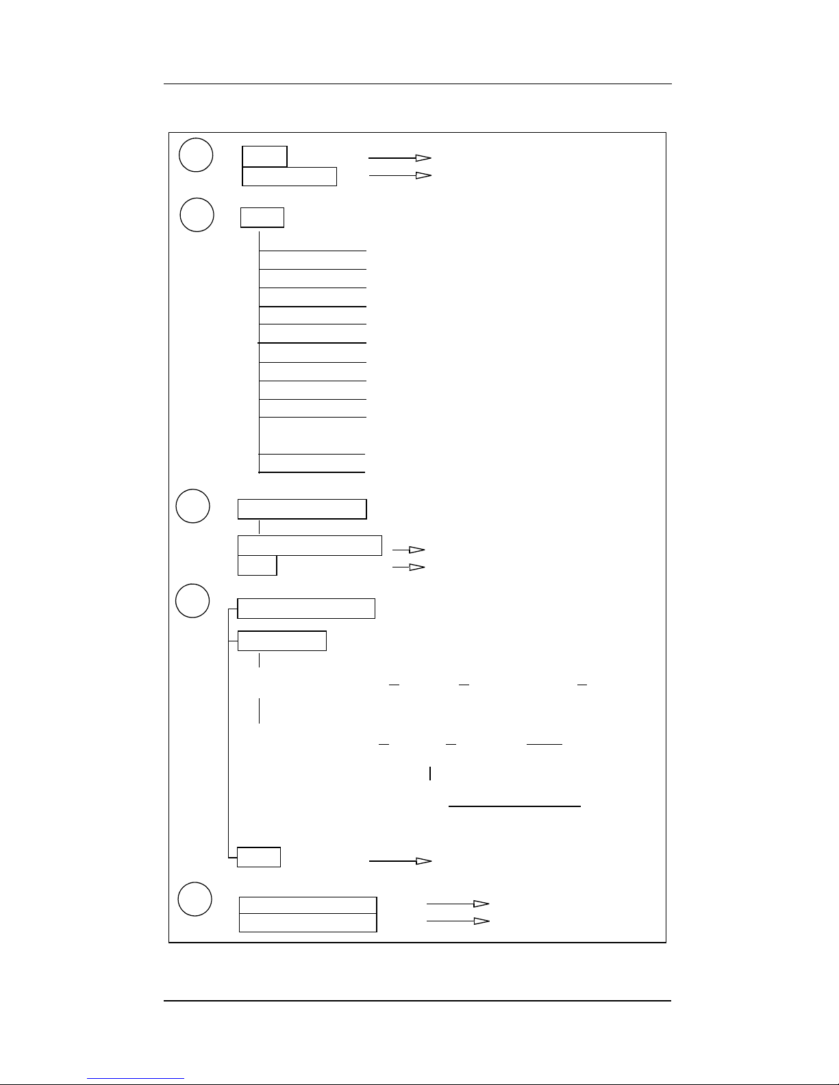
3.2 View/Configure functions (Refer to Figures 3a & 3b)
The view functions allow the user to interrogate the analyser
diagnostics and examine the alarm and fault history logs. No
password is required to access the view functions. The view
functions are updated dynamically and values may change
while they are being viewed. To access this display, press the
MENU key and then select VIEW. If the DIAGNOSTICS option
is chosen, the diagnostics appear as a scrolling list of values
and associated descriptions. There are up to ten diagnostics
depending on which sensors are fitted.
The ↑ ↓ keys are used to switch between the following
diagnostic measurements:
Software version
Oxygen sensor output voltage in mV
Oxygen sensor temperature in °C
Oxygen high calibration point in mV
Oxygen low calibration point in mV
Combustibles sensor output voltage in mV
Combustibles sensor temperature in °C
Combustibles high calibration point in mV
Combustibles low calibration point in mV
(Negative values are unfiltered and will differ from those
displayed at top level)
Probe head temperature in °C (if connected)
If the HISTORY option is chosen, either the alarm or fault history
logs can be examined. The ↑ ↓ keys are used to scroll through
the list of history entries in chronological order.
The configure function allows the user to modify and view the
analyser settings. These functions are password protected. To
access these functions, press the MENU key, select
CONFIGURE and then enter a password. There are two
passwords that can be entered; a supervisor password
(default - 2700) which gives access to CALIBRATE, VIEW,
SERVICE & SETUP and an operator password (default - 2000)
which gives access to CALIBRATE and VIEW only. Both
passwords are factory set and may be changed if required.
Page 14

Servomex 2700 Quickstart Manual
Servomex 2700 Quickstart Manual
8
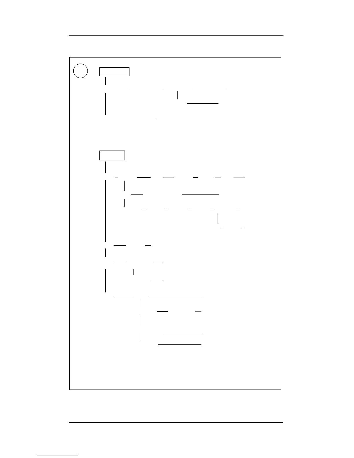
3.3 Analyser setup (Refer to Figures 3a and 3b)
The setup function allows the user to modify and view the
analyser configuration (outputs, alarms, blowback, clock and
passwords).
3.3.1 Setting up the concentration alarms
The control unit has 2 concentration alarms that can be
assigned to either of the 2 possible sensors in the sensor head.
Each concentration has a user configurable level, hysteresis
and polarity (high or low alarm).
Each alarm may also be configured to either freeze (remain
fixed at the last value) or follow (track the concentration
changes) during analyser calibration.
The setup process is as follows:
1. Press the MENU key, then select CONFIGURE, enter a
valid password, select SETUP and then ASSIGN.
2. Select ALARMS to set up the concentration alarms.
3. Select AL1 or AL2 to specify which alarm is to be set up.
4. Select either NONE, OXYGEN or COe to disable the alarm
or to specify the measurement to be the subject of the
alarm.
5. Select either FREEZE or FOLLOW to specify if the alarm is
to be fixed at its current value or to track the concentration
during analyser calibration.
6. Select either LOW or HIGH to specify the alarm as a low
alarm or a high alarm.
7. Use the arrow keys followed by the ENTER key to set the
concentration level at which the alarm is to be triggered.
8. Use the arrow keys followed by the ENTER key to set the
hysteresis on the alarm level.
The alarm assignment is now complete and the user is returned
to the select alarms display (step 3 above) to allow other alarms
to be configured. Use the QUIT or MEASURE key to return to
the assign menu or the measure display as required.
Page 15

Servomex 2700 Quickstart Manual
Servomex 2700 Quickstart Manual
9
3.3.2 Setting up the relay outputs
The Servomex 2700 analyser is supplied with 4 relay outputs
that can be assigned to a number of outputs. Output options
include concentration alarms, analyser fault, calibration in
progress, blowback in progress, autocalibration solenoid valve
control lines and blowback solenoid valve control line.
Default relay assignments are: Relay 1 is concentration
alarm (AL1), Relay 2 is concentration alarm (AL2), Relay 3 is
Analyser Fault (AF) and Relay 4 is the 'IN CALIBRATION'
message. The default assignments can be changed as follows:
1. Press the MENU key, then select CONFIGURE, enter a
valid password, select SETUP and then ASSIGN.
2. Select RELAYS to set up relay outputs.
3. Select 1, 2, 3 or 4 for the relevant relay number.
4. The available assignments are presented as a scrolling list.
Use the ↑ or ↓ keys to select the required assignment and
then press the ENTER key.
The possible relay assignments are:
ALARM 1 Concentration alarm AL1
ALARM 2 Concentration alarm AL2
FAULTS Analyser fault present AF
IN CALIBRATION Calibration in progress
IN BLOWBACK Blowback in progress
GAS 1 Autocalibration gas 1 solenoid valve
GAS 2 Autocalibration gas 2 solenoid valve
GAS 3 Autocalibration gas 3 solenoid valve
BLOWBACK AIR Blowback air solenoid valve
5. The display is returned to the relay number select screen to
allow other relays to be assigned. Use the QUIT or
MEASURE keys to return to the assign menu or
measurement display as required.
Page 16

Servomex 2700 Quickstart Manual
Servomex 2700 Quickstart Manual
10
3.3.3 Setting up the analogue outputs
The Servomex 2700 is supplied with one dedicated analogue
output for each sensor fitted in the sensor head (maximum of
2 analogue outputs). Each analogue output has a minimum and
maximum analogue output range.
For the oxygen sensor, 0-1% is the minimum range and 0-25%
is the maximum. For a 1750702 combustibles sensor,
0-500ppm is the minimum range and 0-30000ppm is the
maximum.
Each analogue output can be configured as either 0-20mA or
4-20mA and to either freeze (remain at the last value) or follow
(track the concentration changes) during calibration and
blowback. The 20mA high point is limited to an over-range of
20.5mA during normal operation. If 4-20mA is selected, then
this can also be configured to under-range that can be set down
to 3.6mA in 0.1mA increments.
An optional "Jam" facility is available to allow the output to set
to 0mA (LOW) or 21mA (HIGH) when an analyser fault is
detected. The outputs are capped so that their value can not
exceed 21mA. The setup process is as follows:
1. Press the MENU key, then select CONFIGURE, enter the
supervisor password, select SETUP and then ASSIGN.
2. Select mA OUTPUTS to set up the analogue outputs.
3. If two sensors are fitted then the analyser will prompt the
user to select the output to be configured. Select either
OXYGEN or COe to specify the output dedicated to the
oxygen sensor or combustibles sensor as required.
4. Select the measuring range required, then ENTER.
5. Select either FREEZE (to freeze the output at the last
value) or FOLLOW (to follow concentration changes during
calibration or blowback).
6. Select either 4-20mA or 0-20mA for the analogue output
type.
7. If 4-20mA is selected, set the low limit desired.
8. Select either LOW, HIGH or NONE to specify whether the
output should be fixed at 0mA (LOW), 21mA (HIGH) or be
unaffected should an analyser fault occur.
The analogue output configuration is now complete. The user is
returned to the sensor selection display (step 3 above) to allow
Page 17

Servomex 2700 Quickstart Manual
Servomex 2700 Quickstart Manual
11
other analogue outputs to be configured. Use the QUIT or
MEASURE keys to return to the assign menu or measurement
display as required.
3.3.4 Setting up a blowback process
The blowback procedure allows the user to apply a burst of a
selected gas to the calibration port of the analyser to back flush
the sample probe and filter. The blowback gas is controlled via
a solenoid valve switched by one of the relay outputs. The
required relay output must be assigned before starting a
blowback operation. The blowback setup will include a start
time and date, a time period between blowback processes, and
a duration for the blowback process.
A blowback operation may be executed by one of the following
means:
1. By timer when the indicated start time and date is reached.
2. By external contact closure between pins 13 and 14 on
terminal block TB2 on control unit PCB.
3. From the keypad using the START BLOWBACK entry in
the setup blowback menu. The supervisor password will be
required and a relay output must be assigned to blowback.
If a start date and time is not set then the blowback can only be
initiated by contact closure or from the keypad. If the period
between blowback processes is set to zero then only a single
timed blowback will be executed. The process for setting the
blowback parameters is as follows:
1. Press the MENU key, then select CONFIGURE, enter a
valid password, select SETUP and then BLOWBACK.
2. Select SET UP BLOWBACK to set the blowback
parameters.
3. Use the arrow keys to define the duration in minutes (MM)
and seconds (SS) of the blowback. Use the ENTER key to
save the value.
4. Use the arrow keys to define the period in days and hours,
between successive blowback processes. Use the ENTER
key to save the value.
Page 18

Servomex 2700 Quickstart Manual
Servomex 2700 Quickstart Manual
12
5. Use the arrow keys to define the start date for the first
blowback. The format will be either day/month/year
(DDMMYY) or month/day/year (MMDDYY) as defined in
the setup clock procedure (see Section 3.3.5).
Use the ENTER key to save the value.
6. Use the arrow keys to define the start time for the first
blowback. Use the ENTER key to save the value.
Successive blowback operations will start at the time and
frequency previously set.
3.3.5 Setting up the real time clock and date format
The process for changing the time, date and the date display
format is as follows:
1. Press the MENU key, then select CONFIGURE, enter a
valid password, select SETUP and then UTILITY.
2. Select CLOCK to change the time and date.
3. The current time and date will be shown on the display for 4
seconds before proceeding. Select YES to continue
changing the time/date or NO to return to the utility menu.
4. Use the arrow keys to define the new date. The date will be
specified either as day/month/year (DDMMYY) or
month/day/year (MMDDYY). Press the ENTER key to save
the new date.
5. Use the arrow keys to define the new time. The format is
hours:minutes (HH:MM).
6. Select either DDMMYY or MMDDYY to specify if dates are
to be displayed in day/month/year or month/day/year
format.
7. The new time and date will be displayed in the selected
format for 4 seconds before returning to the utility menu.
NOTE
After completion of the BLOWBACK process, if FREEZE
has also been selected the analogue outputs remain at
freeze and display shows ‘flushing’ for a fixed period of
120 seconds.
Page 19

Servomex 2700 Quickstart Manual
Servomex 2700 Quickstart Manual
13
3.3.6 Setting a new password
Both passwords are factory set and can be changed as follows:
1. Press the MENU key, then select CONFIGURE, enter a
valid password, select SETUP and then UTILITY.
2. Select PASSW ORD to change the passwords.
3. Select either SUPERVISOR (default - 2700) or
OPERATOR (default - 2000) to define which password is to
be changed.
4. Use the arrow keys to set a new 4 digit password. Use the
ENTER key to save the new password.
5. The new password will be repeated by the analyser. Select
either YES or NO to accept or reject the new password
value.
3.3.7 Setting the auxiliary air option
The auxiliary air is intergrated into the sensor head and
therefore this feature must always be set to YES when the
combustibles sensor is used
1. Press the MENU key, then select CONFIGURE, enter a vaid
password, select SETUP and then UTILITY.
2. Selet AUX AIR to set the auxiliary air status.
3. Select either YES or No to indicate if auxiliary air is applied to
sensor head or not.
3.4 Calibration (Refer to Figures 3a & 3b)
The operator/supervisor passwords are required to access the
calibration functions. The user may either perform a manual
calibration, set up the automatic calibration parameters or
execute an automatic calibration. Servomex recommend that
the oxygen sensor is calibrated every three months and the
combustibles sensor every one month. In some applications the
calibration interval may be extended as a result of operating
experience.
During manual calibration, a LOW calibration must be
made prior to a HIGH calibration for the combustibles
sensor.
Page 20

Servomex 2700 Quickstart Manual
Servomex 2700 Quickstart Manual
14
3.4.1 Manual calibration procedure
1. Press the MENU key, then select CONFIGURE, enter a
valid password and then select CALIBRATE.
2. If two sensors are fitted in the sensor head then select
either OXYGEN or COe for the sensor to be calibrated.
3. Select LOW CAL or HIGH CAL for a low calibration or high
calibration measurement. The procedure for performing the
low or high calibration of an OXYGEN or COe sensor are
the same.
4. Use the arrow keys to set the actual concentration value for
the calibration gas used. Press the ENTER key to accept
the value.
5. Use the arrow keys to set the required tolerance level.
This is the permitted change in the stored calibration value.
Press the ENTER key to accept the value.
6. Apply the calibration gas to the sensor head calibration port
at a flow of 600ml/min. Note: if autocalibration is selected
then the relay outputs will be automatically set to admit the
required calibration gas.
7. Wait until the value displayed on the screen is stable.
Select Y and the ENTER key to accept the measured
value. Note: the displayed value will be calculated using the
existing stored calibration value.
8. Should the user accept a value that is outside of the
tolerance limits an OUT OF TOLERANCE message will be
NOTE
1. When a low calibration is performed, the zero may be
offset between the limits of -500 and +99ppm which
enables the effects of non-CO combustibles to be
compensated for. If this is done, the span calibration
target value should be adjusted by the same amount in
order to maintain accuracy. E.g. if the zero is adjusted by
-50ppm then the span should be set to 450ppm when
using a 500ppm CO calibration gas.
2. In calibration mode negative ppm combustibles values
are unfiltered and will differ from those displayed at top
level.
Page 21

Servomex 2700 Quickstart Manual
Servomex 2700 Quickstart Manual
15
displayed. Select Y or N and press the ENTER key to
accept or refuse the new calibration value.
9. Press MEASURE to view and check the actual
concentration value and then remove the calibration gas
from the analyser.
3.4.2 Automatic calibration
The automatic calibration facility allows the Servomex 2700
analyser to perform routine calibrations without user
intervention. The calibration procedure to be used is specified
by a number of calibration parameters. These parameters must
be set up before an autocalibration is started. The
autocalibration procedure can perform either a low calibration
only or a high and low calibration on either one or both of the
possible sensor combinations in the analyser.
An automatic calibration may be started in three ways:
1. By timer
The automatic calibration will commence when a specified
start time and date is reached. If the start time is not
specified then the timed start is disabled. The calibration
procedure will then be repeated at specified time intervals.
If the specified time interval is zero then only one calibration
process will be done.
2. By contact closure
The automatic calibration will commence when the
automatic calibration initiation contacts (TB2 pins 11
and 12) are closed.
3. From the keypad
From the CALIBRATE menu, select AUTOCALIBRATE
and then START AUTOCAL.
In the automatic calibration process the calibration gases are
admitted to the sensor head via remotely actuated solenoid
valves. These solenoid valves are controlled by the relay
outputs on the control unit PCB. If a single sensor is being
calibrated then two gases and two relay outputs will be required.
If two sensors are being calibrated then three gases and three
relay outputs will be required. The relay outputs to be used are
configured and assigned by the user in the Setup facility (see
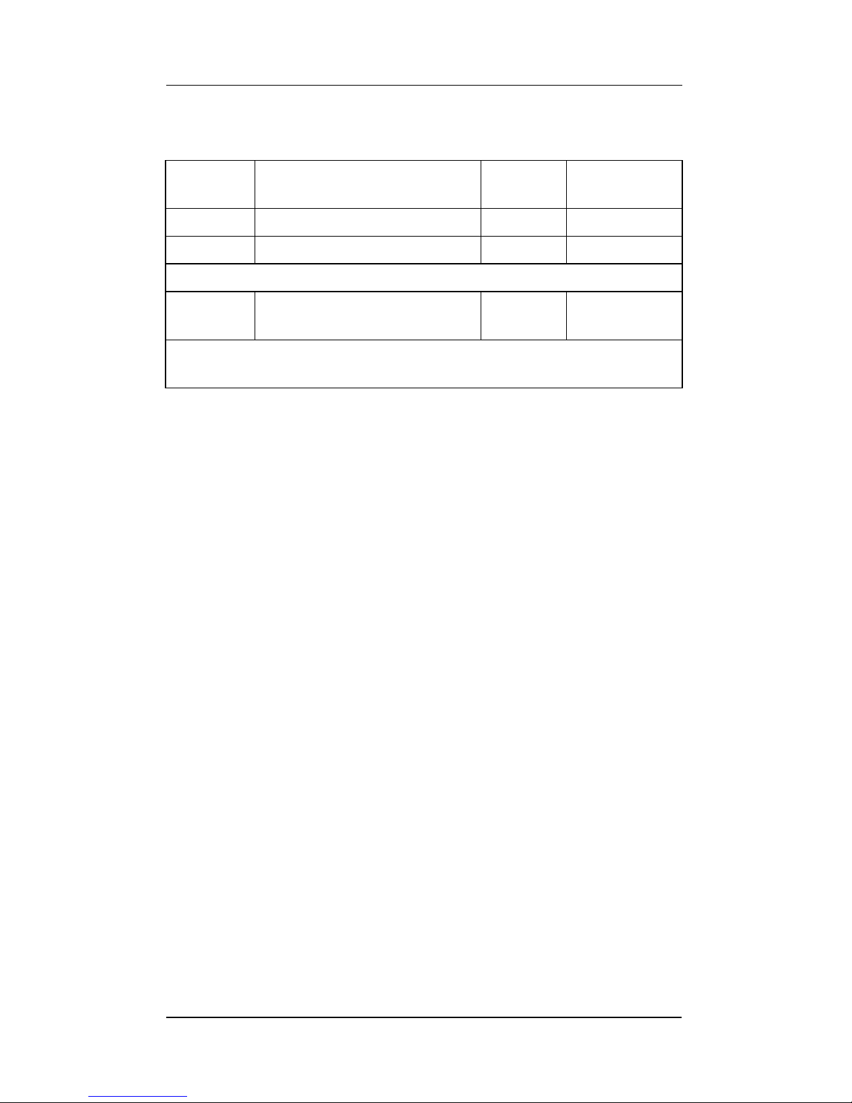
Section 3.3). Table 1 specifies the composition and calibration
duty for the three calibration gases.
Page 22
Servomex 2700 Quickstart Manual
Servomex 2700 Quickstart Manual
16
The following procedure is executed on automatic calibration.
• The relay assignments are checked to ensure that the
required relay contacts have been assigned as solenoid
valve drives. If the relay assignments are incorrect then the
autocalibrate will abort with an appropriate error message
being displayed for 5 seconds.
• The required calibration gases will be admitted to the
sensor head in turn. When each gas is admitted the
process will wait for a user-defined flushing time before
recording the calibration response values. Between 1 and 3
gases will be admitted depending on the calibrations to be
performed.
• The new calibration parameters are calculated and
compared with the existing stored values. If the change in
the calibration parameters is outside of the specified
tolerance values then the autocalibration is aborted, a fault
is raised and the calibration values are not updated.
Table 1: Recommended calibration gas
Solenoid
number
Gas composition Oxygen
sensor
Combustibles
sensor
GAS 1 Zero air (20.95%(v) O
2
)HIGHLOW
GAS 2 0.3%(v) O
2
balance N2 *LOW N/A
* gas composition can be between 0.25% and 2.5% O
2
in N
2
GAS 3 1000ppm(v) CO balance
air**
N/A HIGH
** gas composition can be between 500ppm and 1000ppm
CO balance air for a 1750702 sensor.
Page 23

Servomex 2700 Quickstart Manual
Servomex 2700 Quickstart Manual
17
3.4.3 Setting up the automatic calibration parameters
From the CALIBRATE menu, select AUTO CALIBRATE and
then SET UP AUTO CAL.
1. If two sensors are fitted in the sensor head then select
OXYGEN, COe or OXYGEN & COe to calibrate either the
oxygen sensor only, the combustibles sensor only or both
the oxygen and combustibles sensors.
2. Select LOW CAL ONLY to perform a low point only
calibration for the selected sensors or LOW AND HIGH
CAL to perform both a low point and high point calibration.
3. The user will be prompted to enter a calibration level and
tolerance level (see manual calibration procedure,
Section 3.4.1) for the low (and, if selected, high) calibration
gas for each sensor to be calibrated.
4. Use the arrow keys to select the flushing time to be used.
This is the time delay to allow the reading to stabilise after
each change of gases. The up/down keys alter the
selection by 0.5 minutes over the range 0.5 to 8.0 minutes.
5. Use the arrow keys to set the time period between
successive automatic calibrations. The period is specified
in days with a range 0 to 999 days. If the period is set as 0
then only the first automatic calibration will be made.
6. The current date and time are displayed for five seconds for
reference. Then use the arrow keys to set the start date
and start time for the first automatic calibration. The start
date and time will then be displayed for five seconds.
7. When the automatic calibration parameters are complete
the display will return to the start time entry screen. The
user should press the QUIT key if all is satisfactory.
3.5 Service functions (Refer to Figure 3b)
The supervisor password is required to access the service
functions. The service functions are accessed by pressing the
MENU key, then selecting CONFIGURE, enter a valid
password and then select SERVICE.
Page 24

Servomex 2700 Quickstart Manual
Servomex 2700 Quickstart Manual
18
3.5.1 Testing the analogue outputs
This function allows the user to test and adjust the analogue
outputs. Select SET OUTPUTS, then mA OUTPUTS, then
0mA, 4mA or 20mA and then press ENTER to set all the
analogue outputs to 0, 4 or 20mA. If the span of the analogue
outputs needs adjustment, then potentiometers RV3 and RV4
on the control PCB may be used to set the 20mA point for the
combustibles and oxygen sensor outputs. Select QUIT or press
the MEASURE key to return to normal measurement. The test
function times out after 5 minutes.
3.5.2 Testing the relay outputs
This function allows the user to test the operation of the relay
outputs. Select SET OUTPUTS, then RELAYS and then SET
TO DISABLED or SET TO ENABLED to set all 4 of the relay
outputs to enabled or disabled state. Select QUIT or MEASURE
to return to normal measurement. The test function times out
after 5 minutes.
3.5.3 Delete history
Select SERVICE and then HISTORY. The option to delete the
alarm and fault history logs is then available.
3.6 Software filtration (Refer to Figure 3b)
Due to the fast response of the analyser, it maybe required to
'slow' the measurement signal, allowing it to be integrated into
certain control systems more easily.
This function allows the user to achieve this by setting a filtration
rate for the analyser from 0 to 9, in unit increments; 0 being
unfiltered and 9 being the maximum filtration rate. As a default
the filtration rate is set to 0.
CAUTION
Do not use this function if autocalibration is assigned to the
relays as this could cause damage to the transformer in the
utilities unit.
Page 25

Servomex 2700 Quickstart Manual
Servomex 2700 Quickstart Manual
19
The software filter will also progressively reduce the output
fluctuation of the instrument as the filter setting is increased
from 0 to 9.
1. Press the MENU key, then select CONFIGURE, enter a
valid supervisor password, select SETUP.
2. From the SETUP menu, select FILTER.
3. If two sensors are fitted in the sensor head then select
OXYGEN or COe.
4. Input a value from 0 to 9, then press the QUIT or
MEASURE key when all is satisfactory.
The user may need to make several adjustments to optimise the
filter settings for their process conditions and control system
requirements.
3.7 Language options (Refer to Figure 3b)
The user is able to configure the display of the analyser to one
of three languages; English, French or German.
1. Press the MENU key, then select CONFIGURE, enter a
valid supervisor password and select SETUP.
2. From the SETUP menu, select UTILITY, then LANG and
then select ENGLISH, FRANCAIS, or DEUTSCH.
3. Press the QUIT or MEASURE key, when all is satisfactory.
Page 26

Servomex 2700 Quickstart Manual
Servomex 2700 Quickstart Manual
20
NOTES
Page 27
Servomex 2700 Quickstart Manual
Servomex 2700 Quickstart Manual
21
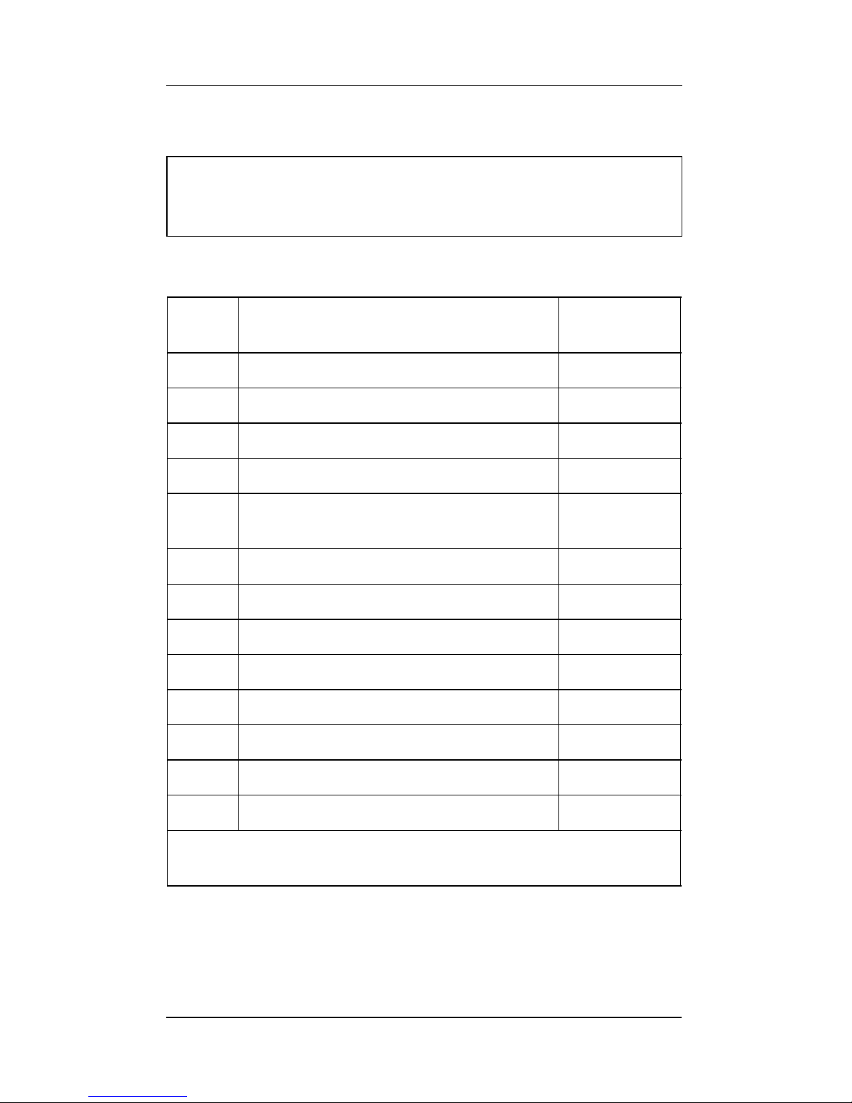
4. ROUTINE MAINTENANCE AND SPARES
4.1 Spare parts
WARNING
2700 spares must be supplied by Servomex
Item Servomex 2700 Control Unit -
description
Spare part
number
1 Control Unit PCB O
2
only S2710903A
2 Control Unit PCB COe only S2710913A
3 Control Unit PCB O2 & COe S2710923A
4 Transformer 4961-1173
5 Keypad Assembly 02710353
02710353A
6 Display Assembly 2553-9307
7 Mains Protection Cover S2710994
8 Purge Kit S2710995
9 Breather 2371-0052
10 Wall Mounting Kit S2710997
11 Rack Mounting Kit S2710996
12 Enclosure Gasket Kit S2700999
13 Fuse Kit (Control Unit & Sensor Head) S2700998 *
* includes: F1.6A HRC (5 x 20mm), F2.5A HRC (5 x 20mm),
F3.15A HRC (5 x 20mm) & F6.3A HRC (5 x 20mm)
Page 28

Servomex 2700 Quickstart Manual
Servomex 2700 Quickstart Manual
22
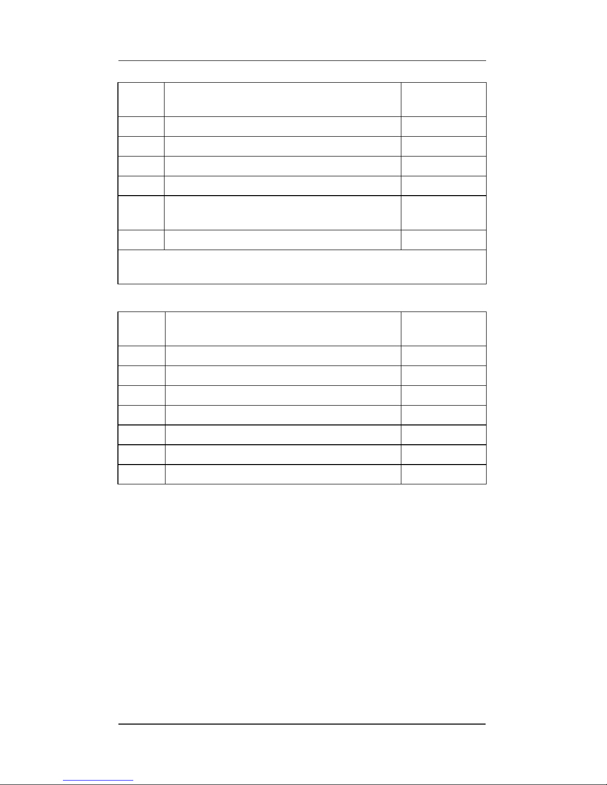
Item Servomex 2700 Sensor Head -
description
Spare part
number
1 Sensor Head O
2
only, 100-120Vac S2720704A
2 Sensor Head Low COe Only, 100-120Vac S2720715A
3 Sensor Head High COe Only, 100-120Vac S2720717A
4 Sensor Head O
2
& Low COe, 100-120Vac S2720716A
5 Sensor Head O
2
& High COe, 100-120Vac S2720718A
6 Sensor Head O
2
only, 220-240Vac S2721704A
7 Sensor Head Low COe only, 220-240Vac S2721715A
8 Sensor Head High COe Only, 220-240Vac S2721717A
9 Sensor Head O
2
& Low COe, 220-240Vac S2721716A
10 Sensor Head O2 & High COe, 220-240Vac S2721718A
11 Solenoid Valve Kit S2720993
12 Solid State Relay (SSR) Kit S2720992
13 Sensor Head PCB O
2
only S2720902A
14 Sensor Head PCB COe only S2720912A
15 Sensor Head PCB O
2
& COe S2720922A
16 Zr 703 Oxygen Cell S2720995
17 Tfx 1750702 Combustibles Cell S1750702
18 ----- ---
19 Cell Connector O
2
only S2720991
20 Cell Connector COe only S2720990
21 Cell Connector O
2
& COe S2720989
22 Aspirator pipe O
2
& O2/COe S2720988
23 Aspirator Kit S2720987
24 Flame Trap Kit 00022907
25 Internal Filter/Flame Arrester Assembly 02720955
26 Thermostat Assembly 02720994
27 Thermistor 2651-7131
28 Band Heater - 120Vac 2653-1825
Page 29
Servomex 2700 Quickstart Manual
Servomex 2700 Quickstart Manual
23
* Item 4 (Probe Support Disc) is required for Items 13 to 16 when
replacing the <700°C filtered probe in a Supported Probe Installation.
Sample Probes continued on next page.
29 Band Heater - 240Vac 2653-1832
30 4" Mounting Gasket Kit S2720985
31 4" Weld-On Flange Mounting Kit S2720984
32 Mains Protection Cover S2720983
33 Enclosure Gasket Kit (Control Unit &
Sensor Head)
S2700999
34 Fuse Kit (Control Unit & Sensor Head) S2700998 *
* includes: F1.6A HRC (5 x 20mm), F2.5A HRC (5 x 20mm),
F3.15A HRC (5 x 20mm) & F6.3A HRC (5 x 20mm)
Item Servomex 2700 Sample Probes -
description
Spare part
number
1 Silicon Carbide Filter Kit S2740998
2 Probe Tube Coupling 2344-2294
3 Probe Shroud S2740996A
4 Probe Support Disc* S2740995
5 Thermal Spacer Flange Kit 02750997
6 High Temperature Standoff 02750995
7 Probe Retention Flange Kit 02750998
Item Servomex 2700 Sensor Head -
description
Spare part
number
Page 30

Servomex 2700 Quickstart Manual
Servomex 2700 Quickstart Manual
24
Servomex 2700 Sample Probes continued.
* Item 4 (Probe Support Disc) is required for Items 13 to 16 when
replacing the <700°C filtered probe in a Supported Probe Installation.
** Items 14,15 and 16. Filter probes exceeding 1.5m in length are only
available as part of a supported probe installation and should not be
used alone.
Item Servomex 2700 Sample Probes -
description
Spare part
number
8 <700°C, Probe, Open-ended, 0.5m S2740701A
9 <700°C, Probe, Open-ended, 1.0m S2740701B
10 <700°C, Probe, Open-ended, 1.5m S2740701C
11 <700°C, Probe, Filtered, 0.5m S2740702A
12 <700°C, Probe, Filtered, 1.0m S2740702B
13 <700°C, Probe, Filtered, 1.5m * S2740702C
14 <700°C, Probe, Filtered, 2.0m * & ** S2740702D
15 <700°C, Probe, Filtered, 2.5m * & ** S2740702E
16 <700°C, Probe, Filtered, 3.0m * & ** S2740702F
17 <1000°C, Probe, Open-ended, 0.5m S2740704A
18 <1000°C, Probe, Open-ended, 1.0m S2740704B
19 <800°C, Probe, Open-ended, 1.5m S2740704C
20 <700°C, Probe, Open-ended, 2.0m S2740704D
21 <1000°C, Probe, Filtered, 0.5m S2740705A
22 <1000°C, Probe, Filtered, 1.0m S2740705B
23 <700°C, Probe Support, 1.5m S2740997C
24 <700°C, Probe Support, 2.0m S2740997D
25 <700°C, Probe Support, 2.5m S2740997E
26 <700°C, Probe Support, 3.0m S2740997F
27 <1750°C, Ceramic Probe, 0.5m 02740707A
28 <1750°C, Ceramic Probe, 1.0m 02740707B
29 <1750°C, Ceramic Probe, 1.5m 02740707C
Page 31
Servomex 2700 Quickstart Manual
Servomex 2700 Quickstart Manual
25
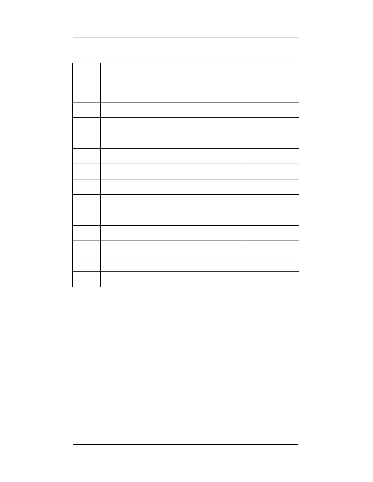
Item Description Spare part
number
1 Quickstart Manual - English 02700003C
2 Quickstart Manual - French 02700013C
3 Quickstart Manual - German 02700023C
4 --- ---
5 --- ---
6 --- ---
7 Installation Manuals - English 02700005C
8 Installation Manuals - French 02700015C
9 Installation Manuals - German 02700025C
10 --- ---
11 --- ---
12 --- ---
13 Service Manual - English 02700002C
Page 32

Servomex 2700 Quickstart Manual
Servomex 2700 Quickstart Manual
26
NOTES
Page 33

Servomex 2700 Quickstart Manual
Servomex 2700 Quickstart Manual
27
5. TECHNICAL SPECIFICATION
5.1 Oxygen measurement performance
* whichever is greater
5.2 Combustibles measurement performance
Item Specification
Analogue output ranges 0-1 min. to 0-25% max. O
2
, in
1% steps
Display resolution 0.01% O
2
Accuracy ±1% of reading or 0.1% O2*
Response time (T
90
),
unfiltered software
<10 seconds (sensor head only at
300ml/min)
Item Specification
Analogue output ranges 1750702 – 0-500 min. to
0-30000ppm max. COe, in
1ppm steps
Display resolution 1ppm(v) COe
Accuracy ±5% of full scale output range
Response time (T
90
),
unfiltered software.
<20 seconds (sensor head only at
300ml/min)
Page 34

Servomex 2700 Quickstart Manual
Servomex 2700 Quickstart Manual
28
5.3 General specification
Analyser inputs and outputs
Digital display 2 line by 16 character back lit LCD.
User interface Menu driven with 8 button tactile keypad.
Analogue outputs One user-configurable 0-20mA or
4-20mA isolated current output dedicated
to each measurement.
Maximum load 1 kΩ. Clamped at 21mA.
Relay outputs Four SPCO relays. Contact rating
3A/250V AC or 1A/28V DC (non
inductive) maximum and 10mA/5V AC or
DC minimum. User assigned as
concentration (2), fault alarms, calibration
in progress, blowback in progress,
autocalibration solenoid valves (2/3) and
blowback solenoid valve control.
Digital inputs Two external digital inputs for
autocalibration and auto-blowback
initiation. Non-isolated, requiring
voltage-free contact closure (or
equivalent) to analyser ground to initiate.
Physical
Size Sensor head 301mm x 330mm x 256mm
Control unit 391mm x 167mm x 260mm
Weight Sensor head <17kg (37.5lbs)
Control unit <10kg (24.3lbs)
Power Supply Two voltage ranges are provided:
100-120Vac, 50/60Hz
220-240Vac, 50/60Hz
Control unit 250VA
Sensor head 600VA
Sensor head and control unit are powered
separately.
Control unit voltage is user set.
Sensor head voltage is factory set.
Page 35

Servomex 2700 Quickstart Manual
Servomex 2700 Quickstart Manual
29
Ambient temperature Operating -10°C to +55°C
(+14°F to +131°F)
Control unit Storage -20°C to +55°C
(-4°F to +131°F)
Ambient temperature Operating -20°C to +70°C
(-4°F to +160°F)
Sensor head Storage -30°C to +80°C
(-2°F to +176°F)
Installation category Category II. Local level power
distribution with over voltage
withstand up to 2,500V in accordance
with IEC 664.
Ingress protection IP66 to IEC529:1989 and
BS EN60529:1992.
Type 4X to NEMA standards
publication no. 250.
Aspirator air requirements Pressure 0.2 to 0.3 barg
(3 to 5 psig).
Flow 1.5 litres/min typical.
Instrument grade compressed air, free
from oil, water and dirt
(See ISA-S7.0.01-1996).
Materials in contact with sample
Oxygen sensor 316 and 310 stainless steel, zirconia,
platinum, alumina, Ni/Fe/Cr alloy, high
temperature sealing glasses.
Combustibles sensor 316 stainless steel, platinum,
platinum/iridium, zirconia, alumina,
corrosion resistant glass, graphite
gasket.
Sensor head 316 and 303 stainless steel, gasket
sealing material.
Sample probes 316 and 310 stainless steel, Haynes
alloy 556, silicon carbide, high
temperature ceramic.
Page 36

Servomex 2700 Quickstart Manual
Servomex 2700 Quickstart Manual
30
Hazardous area classification
Sensor head Non hazardous locations.
Control unit Approved as Ex ic nA nC IIC T5 Gc, Ex tc
IIIB T75°C Dc (Ta = -10°C to +55°C) for
ATEX Group II, Category 3,
Gas and Dust hazardous atmospheres,
certificate number ITS10ATEX47005X.
Approved as non-incendive for:
Class I, Div. 2, Groups A,B,C & D.
Class II, Div. 2, Groups F & G.
Class III, Div. 1 & 2.
Enclosure Type 4X.
T5. Ambient Temperature 55°C max.
(Factory Mutual - FMRC)
Suitable for use in:
Class I, Div. 2, Groups A,B,C & D.
Class II, Div. 1, Groups E,F & G.
Class III, Div. 1.
T5. Ambient Temperature 55°C max.
Enclosure Type 4X.
(Canadian Standards Association - CSA)
Design standards
Conforms to the following standards:
Electromagnetic Compatibility
IEC 61326-1: 1997 (BS EN 61326-1: 1997)
Control unit - Emission Class B
Sensor head - Emission Class A
Electrical Safety
EN61010-1: 1993
IEC1010-1: 1990: amendments A1:1992 and A2:1995
WARNING
To minimise the risk of propagating brushed discharges, do
not install in a high velocity dust laden environment.
Page 37
Servomex 2700 Quickstart Manual
Servomex 2700 Quickstart Manual
31
Figure 3a
1
2
3
4
5
VIEW
Go to 2
VIEW
Diagnostics
CONFIGURATION
ENTER PASSWORD
0000
Operators Password Go to 4
Supervisor Password Go to 5
Operator Password Functions
CALIBRATE / VIEW
CALIBRATE
MANUAL CALIBRATE Oxygen Low Calibration Calibration
COe High Calibration Procedure
CONFIGURE
Go to 3
Set Up Oxygen
AUTO CALIBRATE Auto COe
Calibrate Oxygen & COe
Start Initiate
Auto Automatic
Calibrate Calibration
VIEW Go to 2
Supervisor Password Functions
CALIBRATE / VIEW
SERVICE / SET UP
Go to 4
Go to 6
Software Version
Oxygen sensor output voltage in mV
Oxygen sensor temperature in
o
C
Oxygen Sensor High Cal Point in mV
Oxygen Sensor Low Cal Point in mV
Combustibles sensor output voltage in mV
Combustibles sensor temperature in
o
C
Combustibles Sensor High Cal Point in mV
Combustibles Sensor Low Cal Point in mV
Sensor Head temperature in
o
C (if connected)
Calibration
Procedure
History
Alarm History
Fault History
Page 38
Servomex 2700 Quickstart Manual
Servomex 2700 Quickstart Manual
32
Figure 3b
6
SERVICE
Set Outputs mA Outputs Set 0,4 or 20mA
Relays
Disabled
Enabled
History Delete History
SET-UP
Assign Alarms
AL1
AL2
None
Oxygen
COe
Freeze
Follow
High
Low
Set Up
Procedure
Relays R1, R2, R3 & R4 Set Up Procedure
mA Outputs
Oxygen
Coe
Set
Range
Freeze
Follow
0-20mA
Jam
High/Low/None
4.2mA
Set Low
Point
Jam
High/Low/None
Filter
Oxygen
Coe
Set Filtration 0-9
Blow
Back
Set Up Blow
Back
Blowback Setup Procedure
Start Blow
Back
Initiate Blowback
Utility Clock Clock Setting Procedure
Password
Supervisor
Operator
Password Setting Procedure
Auxiliary Air
Yes
(Yes ialways required with
combustibles)
No
Language English/Francais/Deutsch
Page 39
Servomex 2700 Quickstart Manual
Servomex 2700 Quickstart Manual
33
CONFIGURE
ENTER PASSWORD
0000 (supervisor)
CALIBRATE
MANUAL Oxygen Low Cal Cal Cal
Coe High Cal Level Tol
Calibration Tolerance
Oxygen Low ….0.2%
Oxygen High …1.0%
01750/702
Coe Low…. 100ppm
Coe High …100ppm
AUTO Setup Oxygen Low Cal Cal Cal
Autocal Coe Low & High Cal Level Tol.
Oxygen & Coe
SETUP
Minimum Output Ranges
ASSIGN ma Oxygen Coe 01750/702 Coe …500ppm
Output Coe
FILTER Oxygen Filter Settings
Coe Oxygen ….. 4
Coe ……… 5
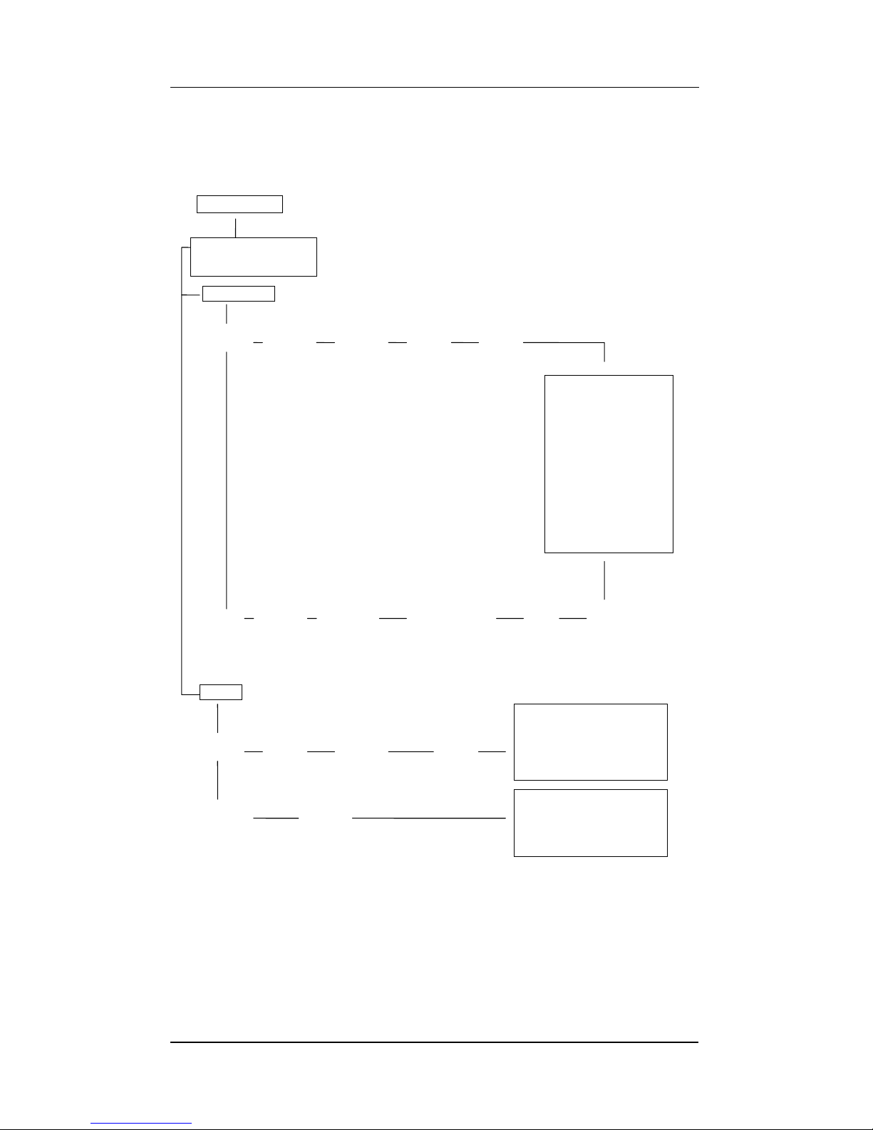
It is advised that the parameters for Calibration Tolerances,
Combustibles Output Ranges and Filters are set as follows.
Figure 3c
Page 40

Servomex 2700 Quickstart Manual
Servomex 2700 Quickstart Manual
34
NOTES
 Loading...