

Page 1

SR10M/SR15M
FLEX-WING MECHANICAL LEVEL
LIFT ROTARY CUTTER/SHREDDER
Published 02-12-03 Part No. 00759799C
OPERATOR'S MANUAL
This Operator's Manual is an integral part of the safe operation
of this machine and must be maintained with the unit at all times.
READ, UNDERSTAND, and FOLLOW the Safety and Operation
Instructions contained in this manual before operating the
equipment.
RHINO
1020 S. Sangamon Ave.
Gibson City , IL 60936
800-446-5158
Email: parts@servis-rhino.com
®
© 2004 Alamo Group Inc.
$0.00
Page 2

TO THE OWNER/OPERATOR/DEALER
All implements with moving parts are potentially hazardous. There is no substitute for a cautious, safe-minded
operator who recognizes the potential hazards and follows reasonable safety practices. The manufacturer has
designed this implement to be used with all its safety equipment properly attached to minimize the chance of
accidents.
BEFORE YOU START!! Read the safety messages on the implement and shown in your manual.
Observe the rules of safety and common sense!
WARRANTY INFORMATION:
Read and understand the complete Warranty Statement found in this Manual. Fill out the Warranty Registration Form
in full and return it within 30 Days. Make certain the Serial Number of the Machine is recorded on the Warranty Card
and on the Warranty Form that you retain. The use of "will-fit" parts will void your warranty and can cause catastrophic
failure with possible injury or death.
Page 3

BE SAFE!
BE ALERT!
BE ALIVE!
BE TRAINED
before operating
the Mower!
Safety T raining
Makes the Difference
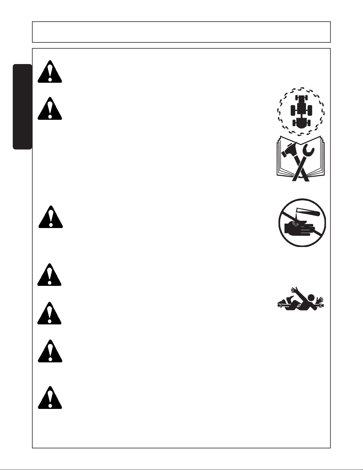
In order to reduce accidents and enhance the safe operation of mowers, Alamo Group Ag Division, in
cooperation with other industry manufacturers has developed the AEM/FEMA Industrial and Agricultural
Mower Safety Practices video and guide book.
The video will familiarize and instruct mower-tractor operators in safe practices when using industrial and
agricultural mowing equipment. It is important that Every Mower Operator be educated in the operation of
their mowing equipment and be able to recognize the potential hazards that can occur while operating a
mower . This video, along with the mower operator’ s manual and the warning messages on the mower, will
significantly assist in this important education.
Y our Authorized Alamo Ag Dealer may have shown this video and presented you a DVD V ideo when you
purchased your mower . If you or any mower operator have not seen this video, Watch the Video, Read
this Operator’ s Manual, and Complete the Video Guidebook before operating your new mower . If you
do not understand any of the instructions included in the video or operator’s manual or if you have any
questions concerning safety of operation, contact your supervisor, dealer or Alamo Group Ag.
If you would like a VHS video tape of the video, please email AEMVideo@alamo-group.com or Fax AEM
VHS V ideo at (830) 372-9529 or mail in a completed copy of the form on the back of this page to AEM
VHS V ideo 1502 E W alnut Street, Seguin, TX 78155. and request the VHS video version. Please include
your name, mailing address, mower model and serial number .
Every operator should be trained for each piece of equipment (Tractor and Mower), understand the intended
use, and the potential hazards before operating the equipment.
Page 4

Alamo Group Ag. Division is willing to provide
one (1) AEM Mower Safety Practices Video
Please Send Me: VHS Format – AEM/FEMA Mower Operator Safety Video
DVD Format – AEM/FEMA Mower Operator Safety Video
Mower Operator’s Manual
AEM Mower Operator’s Safety Manual
Requester Name:
Requester Address:
City
State
Zip Code
Mower Model: Serial Number:
Date Purchased: Dealer Salesperson:
Dealership Name: Dealership Location:
Phone:
Mail to:
Or Fax to:
Or Email to:
AEM V ideo Services
1502 E Walnut street
Seguin, TX 78155
(830) 372-9529
AEMVideo@alamo-group.com
Page 5

TABLE OF CONTENTS
SAFETY SECTION ................................................................................................................................1-1
Safety Information .....................................................................................................................1-2
Decal Location ...........................................................................................................................1-13
Federal Laws & Regulations ....................................................................................................... 1-18
INTRODUCTION SECTION ................................................................................................................... 2-1
ASSEMBLY SECTION .......................................................................................................................... 3-1
Blade Carrier Attachment .......................................................................................................... 3-2
Tongue Attachment ................................................................................................................... 3-3
Center Axle Attachment............................................................................................................. 3-3
Level Rod Attachment ............................................................................................................... 3-4
Wing Section Attachment .......................................................................................................... 3-5
Wing Axle Attachment ...............................................................................................................3-5
Axle Adjustment Rod Attachment .............................................................................................. 3-6
Wheel Attachment .....................................................................................................................3-6
Spring Assembly Attachment.....................................................................................................3-8
Center Axle Cylinder Attachment............................................................................................... 3-8
Wing Section Cylinder Attachment ............................................................................................3-9
Hose Bracket Attachment .......................................................................................................... 3-10
Deflector Attachment ................................................................................................................. 3-10
Driveline Attachment ................................................................................................................. 3-11
Equal Angle Jackshaft................................................................................................................ 3-12
Winch Assembly........................................................................................................................ 3-13
Three Spool Control Valve Installation.......................................................................................3-13
OPERATION SECTION ......................................................................................................................... 4-1
MAINTENANCE SECTION .................................................................................................................... 5-1
Lubrication Information ..............................................................................................................5-2
Tongue ......................................................................................................................................5-3
Center & Wing Gearbox.............................................................................................................5-3
Divider Gearbox.........................................................................................................................5-4
Drivelines....................................................................................................................................5-4
Protective Shields ......................................................................................................................5-5
Blades ....................................................................................................................................... 5-7
Slip Clutches..............................................................................................................................5-9
Hydraulic Hoses.........................................................................................................................5-10
Skid Shoes ................................................................................................................................5-10
Torque Chart .............................................................................................................................. 5-11
Disassembly & Assembly of Gearbox ........................................................................................5-12
Servis Rhino® is a registered trademark of Alamo Group Inc.
Page 6

Page 7

SAFETY
SECTION
Safety Section 1-1
Page 8
SAFETY
A safe and careful operator is the best operator. Safety is of primary importance to the
manufacturer and should be to the owner/operator. Most accidents can be avoided by being
aware of your equipment, your surroundings, and observing certain precautions. The first
section of this manual includes a list of Safety Messages that, if followed, will help protect the
operator and bystanders from injury or death. Read and understand these Safety Messages
before assembling, operating or servicing this mower. This equipment should only be operated by those persons who have read the Manual, who are responsible and trained, and who
know how to do so safely and responsibly.
SAFETY
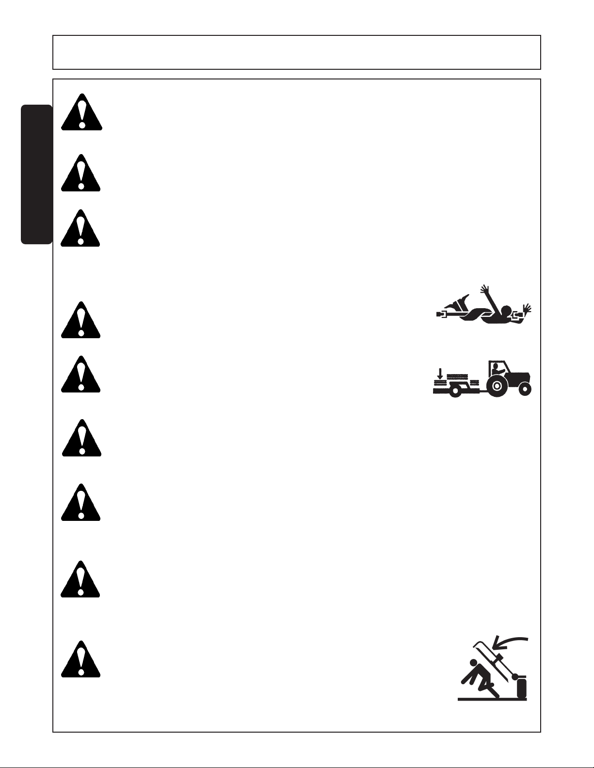
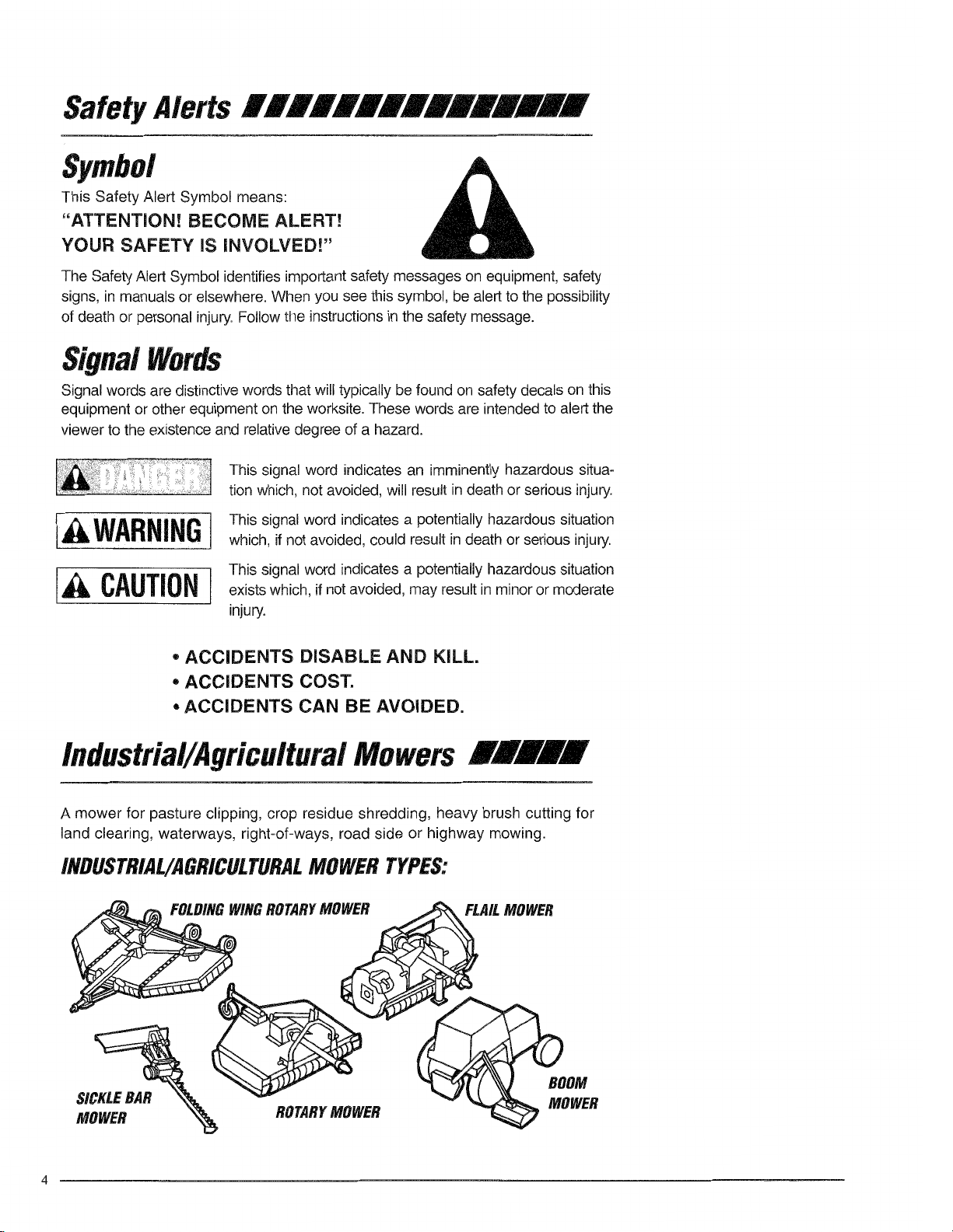
The Safety Alert Symbol combined with a Signal Word, as seen below, is used throughout this
manual and on decals which are attached to the equipment. The Safety Alert Symbol means:
“ATTENTION! BECOME ALERT! YOUR SAFETY IS INVOLVED!” The Symbol and Signal
Word are intended to warn the owner/operator of impending hazards and the degree of
possible injury faced when operating this equipment..
Practice all usual and customary safe working precautions and
above all---remember safety is up to YOU. Only YOU can prevent
serious injury or death from unsafe practices.
CAUTION! The lowest level of Safety Message; warns of possible injury. Decals
located on the Equipment with this Signal Word are Black and Yellow.
WARNING! Serious injury or possible death! Decals are Black and Orange.
DANGER! Imminent death/critical injury. Decals are Red and White. (SG-1)
SR15 10-01
© 2004 Alamo Group Inc.
Safety Section 1-2
Page 9
SAFETY
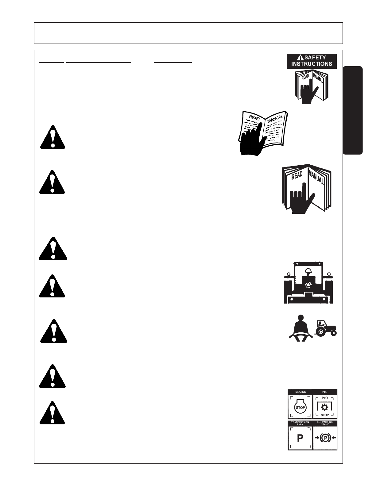
READ, UNDERSTAND, and FOLLOW the following Safety
Messages. Serious injury or death may occur unless care is
taken to follow the warnings and instructions stated in the Safety
Messages. Always use good common sense to avoid hazards.
(SG-2)
SAFETY
PELIGRO!
DANGER!
WARNING!
WARNING!
Si no lee Ingles, pida ayuda a alguien que si lo lea
para que le traduzca las medidas de seguridad. (SG-3)
Never operate the Tractor or Implement until you have read and
completely understand this Manual, the Tractor Operator’s Manual,
and each of the Safety Messages found in the Manual or on the
Tractor and Implement. Learn how to stop the tractor engine
suddenly in an emergency. Never allow inexperienced or untrained
personnel too operate the Tractor and Implement without supervision.
Make sure the operator has fully read and understood the manuals
prior to operation. (SG-4)
Always maintain the safety decals in good readable condition. If the
decals are missing, damaged, or unreadable, obtain and install replacement decals immediately. (SG-5)
Make certain that the “Slow Moving Vehicle” (SMV) sign is installed in
such a way as to be clearly visible and legible. When transporting the
Equipment use the Tractor flashing warning lights and follow all local
traffic regulations. (SG-6)
¡LEA EL
INSTRUCTIVO!
WARNING! Operate this Equipment only with a Tractor equipped with an approved
roll-over-protective system (ROPS). Always wear seat belts. Serious
injury or even death could result from falling off the tractor--particularly
during a turnover when the operator could be pinned under the
ROPS. (SG-7)
WARNING!
DANGER!
SR15 10/01
© 2004 Alamo Group Inc.
Do not modify or alter this Implement. Do not permit anyone to modify or alter this Implement,
any of its components or any Implement function. (SG-8)
BEFORE leaving the tractor seat, always engage the brake and/or set
the tractor transmission in parking gear, disengage the PTO, stop the
engine, remove the key, and wait for all moving parts to stop. Place the
tractor shift lever into a low range or parking gear to prevent the tractor
from rolling. Never dismount a Tractor that is moving or while the engine
is running. Operate the Tractor controls from the tractor seat only.
(SG-9)
Safety Section 1-3
Page 10
SAFETY
DANGER!
DANGER!
SAFETY
WARNING!
DANGER!
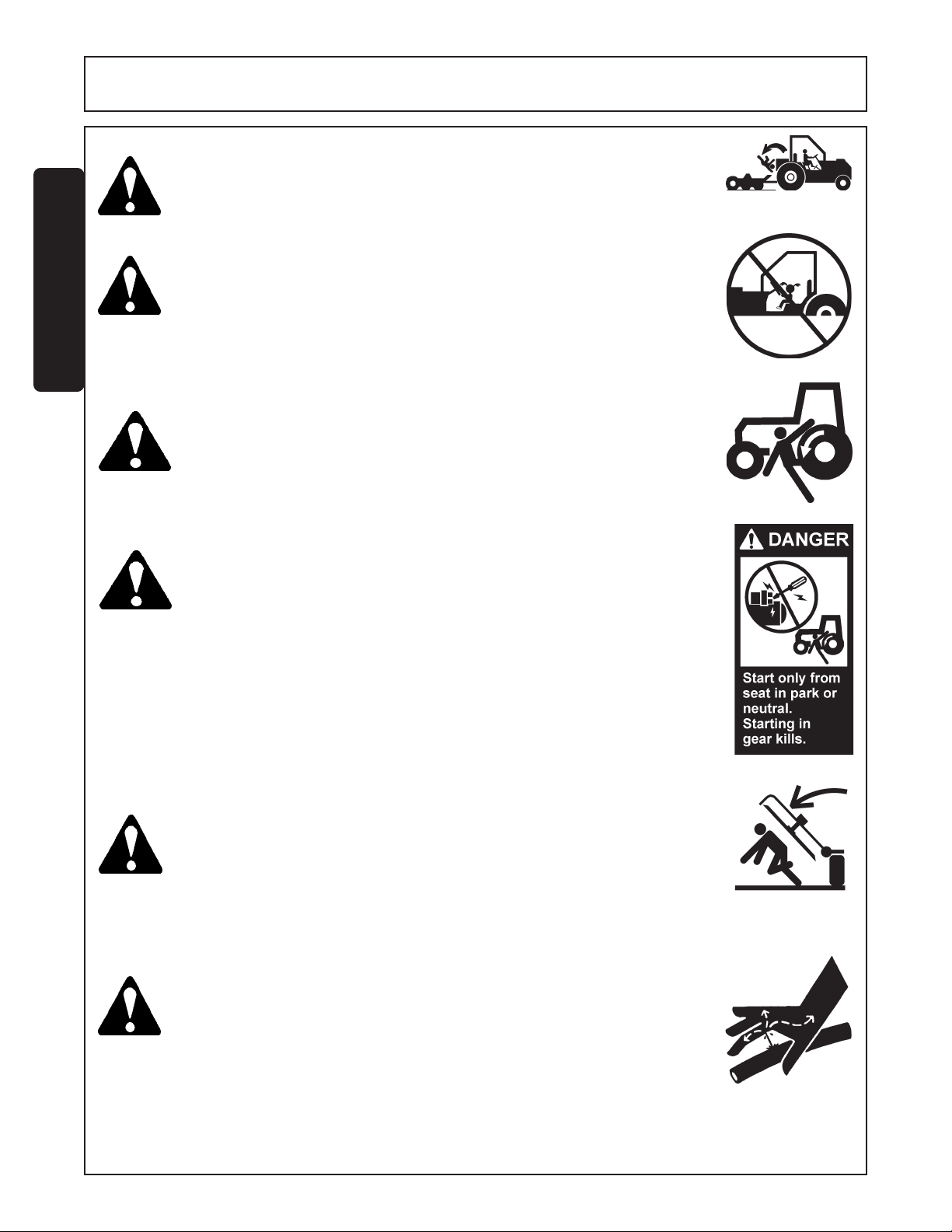
Never allow children or other persons to ride on the Tractor or Implement.
Falling off can result in serious injury or death. (SG-10)
Never allow children to operate or ride on the Tractor or Implement.
(SGM-11)
Do not mount the Tractor while the tractor is moving. Mount the
Tractor only when the Tractor and all moving parts are completely
stopped. (SG-12)
Start tractor only when properly seated in the Tractor seat. Starting a
tractor in gear can result in injury or death. Read the Tractor operators
manual for proper starting instructions. (SG-13)
DANGER!
DANGER!
SR15 10-01
© 2004 Alamo Group Inc.
Never work under the Implement, the framework, or any lifted
component unless the Implement is securely supported or blocked
up to prevent sudden or inadvertent falling which could cause
serious injury or even death. (SG-14)
Do not operate this Equipment with hydraulic oil leaking. Oil is
expensive and its presence could present a hazard. Do not check for
leaks with your hand! Use a piece of heavy paper or cardboard.
High-pressure oil streams from breaks in the line could penetrate the
skin and cause tissue damage including gangrene. If oil does
penetrate the skin, have the injury treated immediately by a physician knowledgeable and skilled in this procedure. (SG-15)
Safety Section 1-4
Page 11
SAFETY
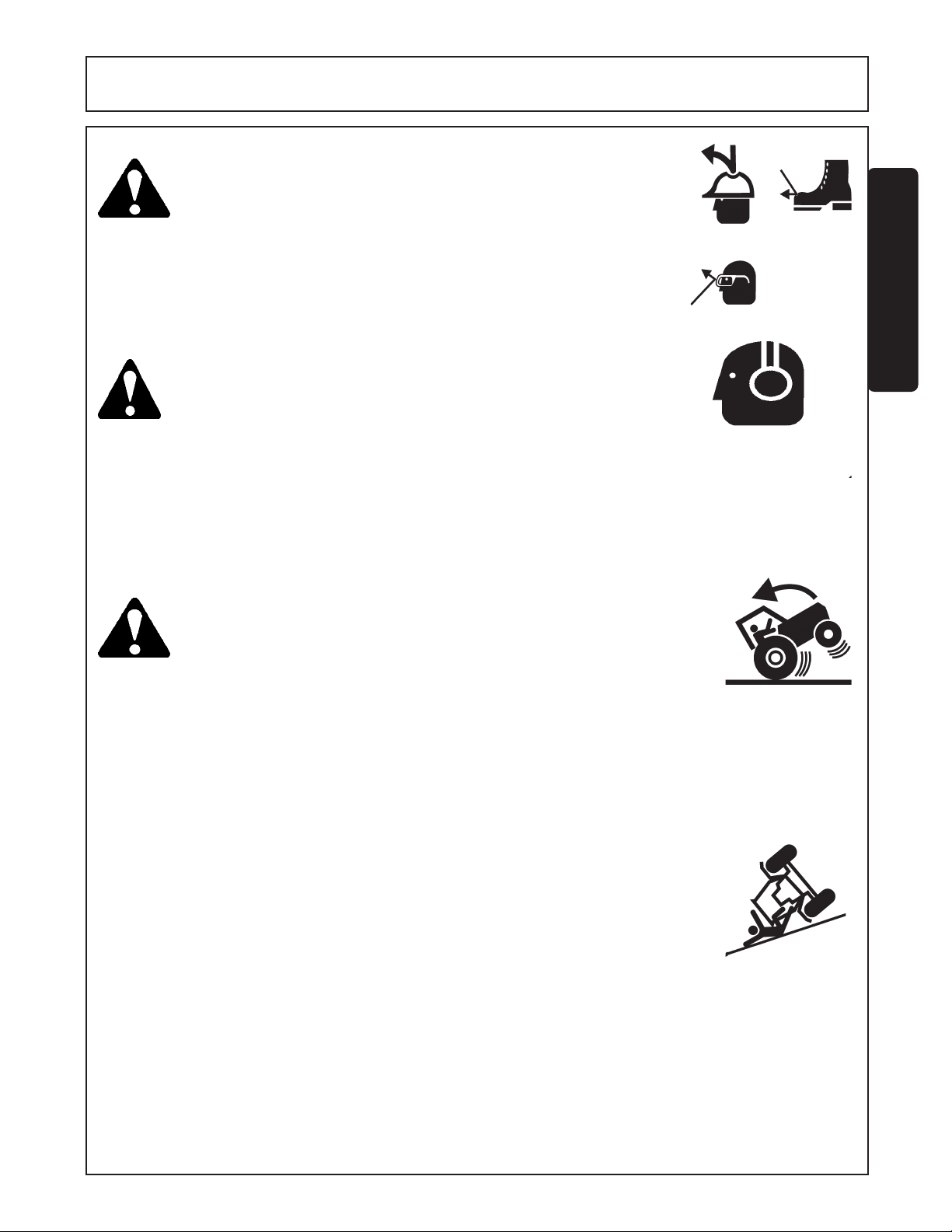
WARNING! The operator and all support personnel should wear hard hats,
safety shoes, safety glasses, and proper hearing protection at all
times for protection from injury including injury from items thrown by
the equipment. (SG-16)
SAFETY
CAUTION!
WARNING!
SR15 10/01
PROLONGED EXPOSURE TO LOUD NOISE MAY CAUSE PERMANENT HEARING LOSS! Tractors with or without an Imple-
ment attached can often be noisy enough to cause permanent
hearing loss. We recommend that you always wear hearing protection if the noise in the Operator’s position exceeds 80db. Noise
over 85db over an extended period of time will cause severe
hearing loss. Noise over 90db adjacent to the Operator over an
extended period of time will cause permanent or total hearing loss.
Note: Hearing loss from loud noise [from tractors, chain saws,
radios, and other such sources close to the ear] is cumulative over
a lifetime without hope of natural recovery. (SG-I7)
Transport only at safe speeds. Serious accidents and injuries can
result from operating this equipment at unsafe speeds. Understand
the Tractor and Implement and how it handles before transporting on
streets and highways. Make sure the Tractor steering and brakes are
in good condition and operate properly.
Before transporting the Tractor and Implement, determine the safe
transport speeds for you and the equipment. Make sure you
abide by the following rules:
1. Test the tractor at a slow speed and increase the speed slowly.
Apply the Brakes smoothly to determine the stopping
characteristics of the Tractor and Implement.
As you increase the speed of the Tractor the stopping distance
increases. Determine the maximum safe transport speed for
you and this Equipment.
2. Test the equipment at a slow speed in turns. Increase the speed
through the turn only after you determine that it is safe to operate
at a higher speed. Use extreme care and reduce your speed when
turning sharply to prevent the tractor and implement from turning
over. Determine the maximum safe turning speed for you and this
equipment before operating on roads or uneven ground.
3. Only transport the Tractor and Implement at the speeds that you
have determined are safe and which allow you to properly control the
equipment.
Be aware of the operating conditions. Do not operate the Tractor with
weak or faulty brakes. When operating down a hill or on wet or rain
slick roads, the braking distance increases: use extreme care and
reduce your speed. When operating in traffic always use the Tractor’s
flashing warning lights and reduce your speed. Be aware of traffic
around you andwatch out for the other guy. (SG-19)
Safety Section 1-5
© 2004 Alamo Group Inc.
Page 12
SAFETY
WARNING!
WARNING! Periodically inspect all moving parts for wear and replace when
SAFETY
WARNING!
Never attempt to lubricate, adjust, or remove material from the Implement while it is in motion
or while tractor engine is running. Make sure the tractor engine is off before working on the
Implement! (SG-20)
necessary with authorized service parts. Look for loose fasteners,
worn or broken parts, and leaky or loose fittings. Make sure all pins
have cotter pins and washers. Serious injury may occur from not
maintaining this machine in good working order. (SG-21)
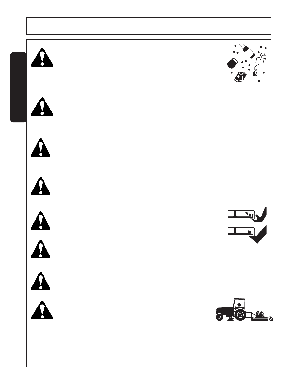
Always read carefully and comply fully with the manufacturers
instructions when handling oil, solvents, cleansers, and any other
chemical agent. (SG-22)
DANGER!
DANGER!
DANGER!
WARNING!
Never run the tractor engine in a closed building or without adequate ventilation. The
exhaust fumes can be hazardous to your health. (SG-23)
KEEP AWAY FROM ROTATING ELEMENTS to prevent entanglement
and possible serious injury or death. (SG-24)
Never allow children to play on or around Tractor or Implement. Children can slip or fall off the
Equipment and be injured or killed. Children can cause the Implement to shift or fall crushing
themselves or others. (SG-25)
Do not exceed the rated PTO speed for the Implement. Excessive PTO
speeds can cause Implement driveline or blade failures resulting in
serious injury or death. (SG-26)
SR15 10-01
© 2004 Alamo Group Inc.
Safety Section 1-6
Page 13
SAFETY
DANGER!
DANGER! Operate the Tractor and/or Implement controls only while properly
WARNING!
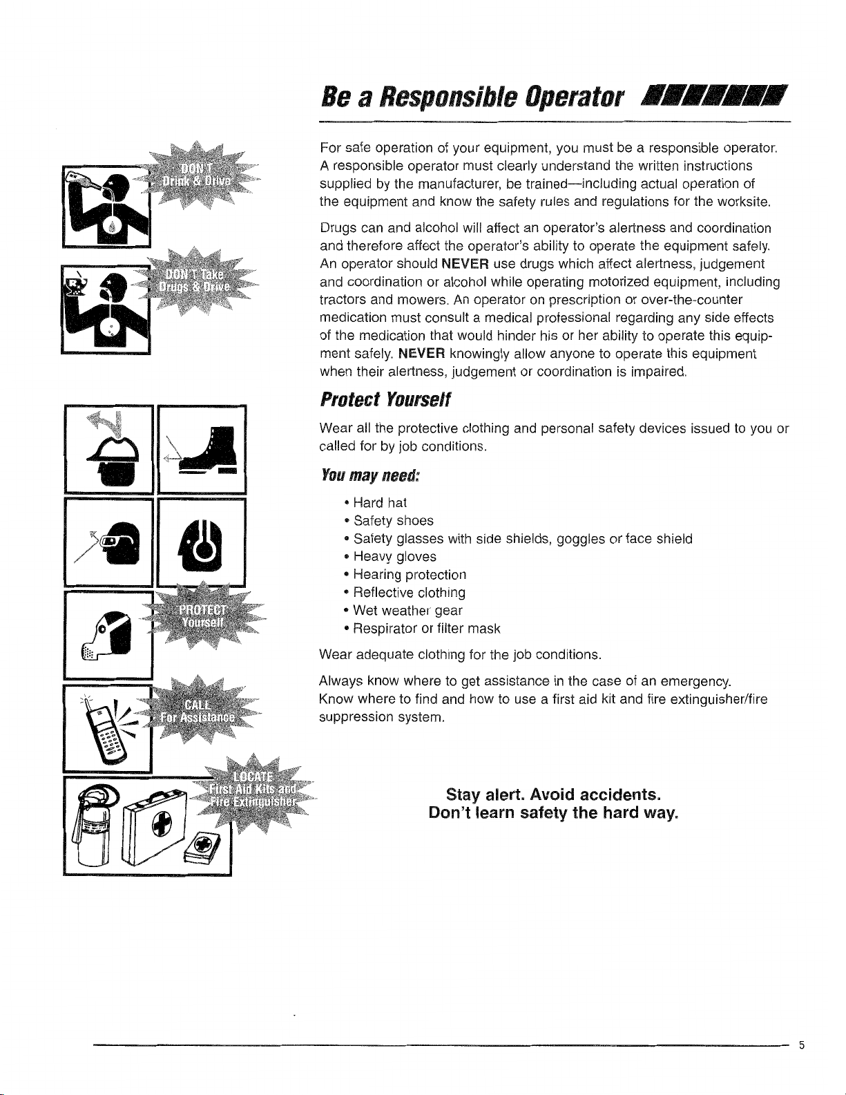
NEVER use drugs or alcohol immediately before or while operating
the Tractor and Implement. Drugs and alcohol will affect an operator’s
alertness and coordination and therefore affect the operator’s ability to
operate the equipment safely. Before operating the Tractor or
Implement, an operator on prescription or over-the-counter
medication must consult a medical professional regarding any side
effects of the medication that would hinder their ability to operate
the Equipment safely. NEVER knowingly allow anyone to operate
this equipment when their alertness or coordination is impaired.
Serious injury or death to the operator or others could result if the
operator is under the influnce of drugs or alcohol. (SG-27)
seated in the Tractor seat with the seat belt securely fastened around
you. Inadvertent movement of the Tractor or Implement may cause
serious injury or death.
Mow only in conditions where you have clear visibility in daylight or with
adequate artificial lighting. Never mow in darkness or foggy conditions
where you cannot clearly see at least 100 yards in front and to the sides of
the tractor and mower. Make sure that you can clearly see and identify
passersby, steep slopes, ditches, drop-offs, overhead obstructions, power
lines, debris and foreign objects. If you are unable to clearly see this type
of items discontinue mowing. (SGM-1)
(SG-29)
SAFETY
DANGER!
DANGER!
DANGER!
SR15 10/01
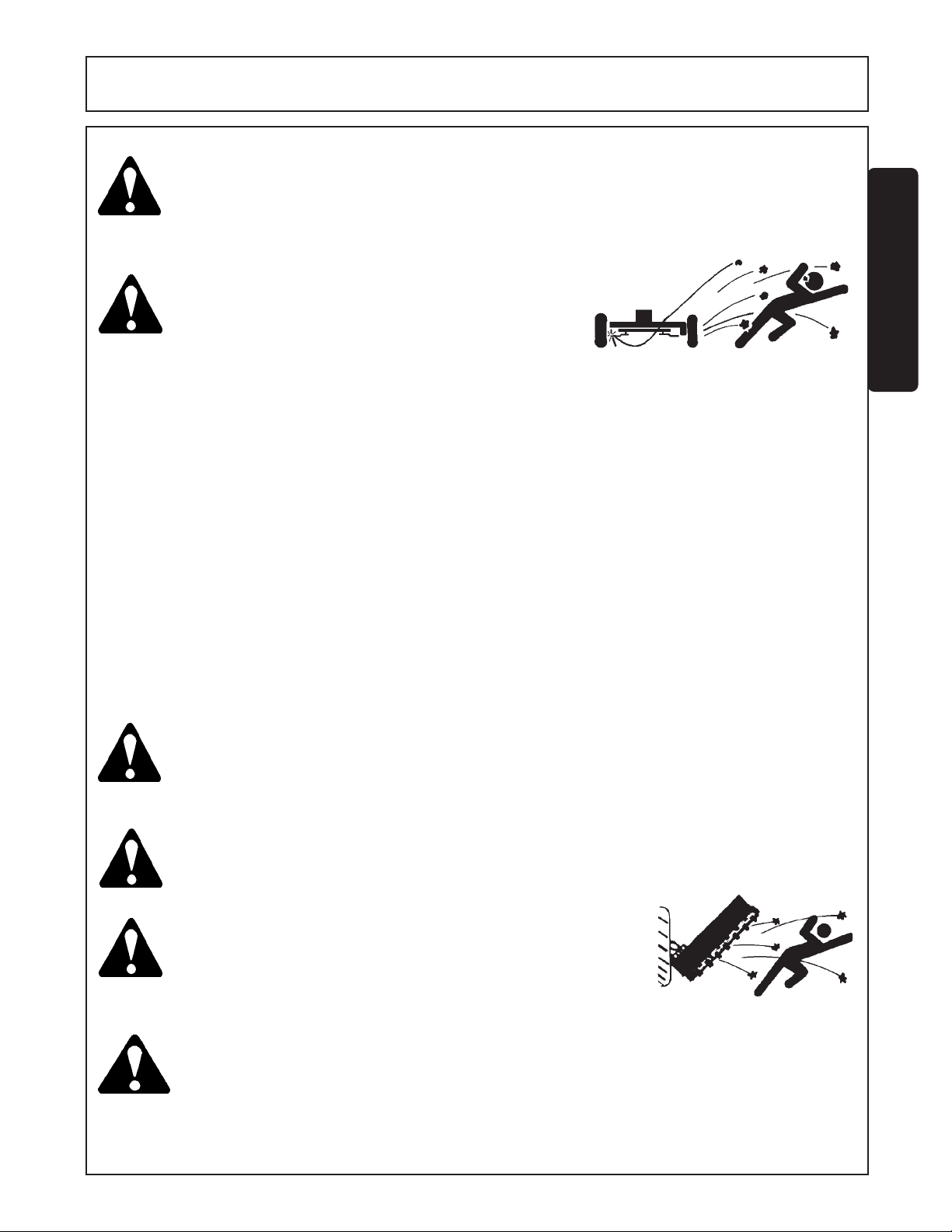
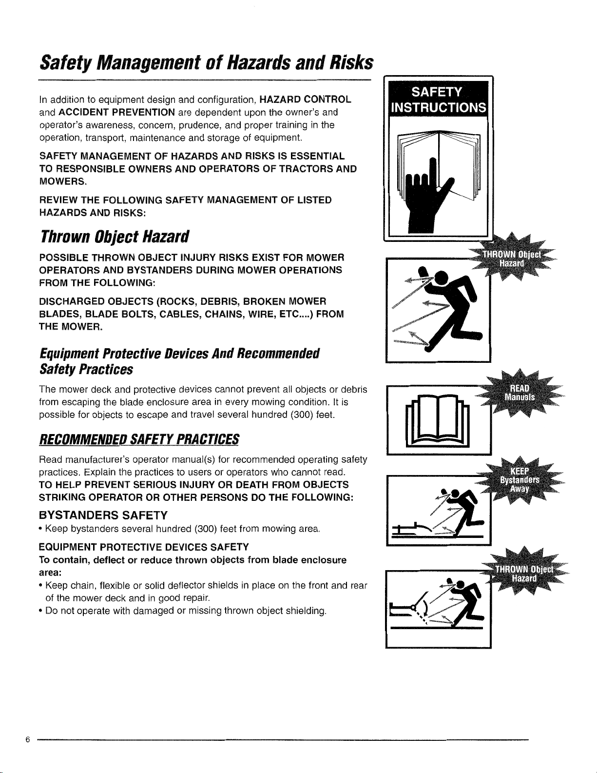
There are obvious and hidden potential hazards in the operation of
this Mower. REMEMBER! This machine is often operated in heavy
brush and in heavy weeds. The Blades of this Mower can throw
objects if shields are not properly installed and maintained. Serious
injury or even death may occur unless care is taken to insure the
safety of the operator, bystanders, or passersby in the area. Do not
operate this machine with anyone in the immediate area. Stop
mowing if anyone is within 100 yards of mower. (SGM-2)
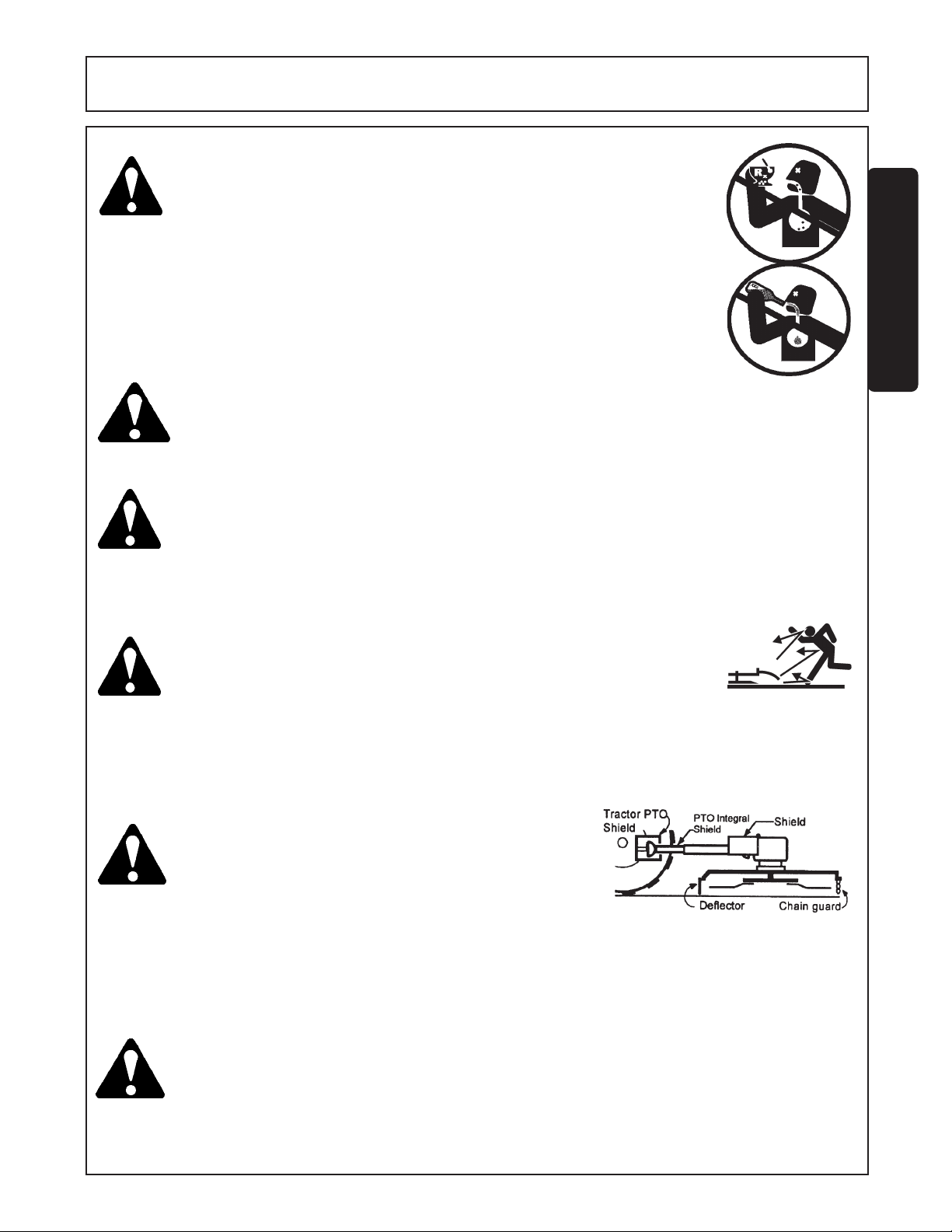
All Safety Shields, Guards and Safety devices including (but not limited to) - the Deflectors, Chain Guards,
Steel Guards, Gearbox Shields, PTO integral shields ,
and Retractable Door Shields should be used and
maintained in good working condition. All safety devices should be inspected carefully at least daily for
missing or broken components. Missing, broken, or
worn items must be replaced at once to reduce the
possibility of injury or death from thrown objects, entanglement, or blade contact. (SGM-3)
The rotating parts of this machine have been designed and tested for
rugged use. However, the blades could fail upon impact with heavy,
solid objects such as metal guard rails and concrete structures.
Such impact could cause the broken objects to be thrown outward
at very high velocities. To reduce the possibility of property damage, serious injury, or even death, never allow the cutting blades to
contact such obstacles. (SGM-4)
Safety Section 1-7
© 2004 Alamo Group Inc.
Page 14
SAFETY
WARNING!
WARNING!
SAFETY
WARNING!
WARNING!
WARNING!
Extreme care should be taken when operating near loose objects
such as gravel, rocks, wire, and other debris. Inspect the area before
mowing. Foreign objects should be removed from the site to prevent
machine damage and/or bodily injury or even death. Any objects
that cannot be removed must be clearly marked and carefully
avoided by the operator. Stop mowing immediately if blades strike
a foreign object. Repair all damage and make certain rotor or blade
carrier is balanced before resuming mowing.
Many varied objects, such as wire, cable, rope, or chains, can become
entangled in the operating parts of the mower head. These items could
then swing outside the housing at greater velocities than the blades.
Such a situation is extremely hazardous and could result in serious
injury or even death. Inspect the cutting area for such objects before
mowing. Remove any like object from the site. Never allow the cutting
blades to contact such items. (SGM-6)
Mow at the speed that you can safely operate and control the tractor and
mower. Safe mowing speed depends on terrain condition and grass
type, density, and height of cut. Normal ground speed range is from 0
to 5 mph. Use slow mowing speeds when operating on or near steep
slopes, ditches, drop-offs, overhead obstructions, power lines, or when
debris and foreign objects are to be avoided. (SGM-7)
Avoid mowing in reverse direction when possible. Check to make sure
there are no persons behind the mower and use extreme care when
mowing in reverse. Mow only at a slow ground speed where you can
safely operate and control the tractor and mower. Never mow an area
that you have not inspected and removed debris or foreign material. (SGM-
8)
Do not put hands or feet under mower decks. Blade Contact can result
serious injury or even death. Stay away until all motion has stopped
and the decks are securely blocked up. (SGM-9)
(SGM-5)
DANGER!
WARNING!
WARNING!
SR15 10-01
© 2004 Alamo Group Inc.
Replace bent or broken blade with new blades. NEVER ATTEMPT
TO STRAIGHTEN OR WELD ON BLADES SINCE THIS WILL
LIKELY CRACK OR OTHERWISE DAMAGE THE BLADE WITH
SUBSEQUENT FAILURE AND POSSIBLE SERIOUS INJURY FROM
THROWN BLADES. (SGM-10)
Do not mow with two machines in the same area except with Cab tractors
with the windows closed. (SGM-11)
Follow these guidelines to reduce the risk of equipment and grass fires
while operating, servicing, and repairing the Mower and Tractor:
-Equip the Tractor with a fire extinguisher in an accesible location.
-Do Not operate the Mower on a Tractor with an underframe exhaust.
-Do Not smoke or have an open flame near the Mower and Tractor .
-Do Not drive into burning debris or freshly burnt areas.
-Ensure slip clutches are properly adjusted to prevent excessive slippage
and plate heating.
-Never allow clippings or debris to collect near drivelines, slip clutches,
and gearboxes. Periodically shut down the Tractor and Mower and clean
clippings and collected debris from the mower deck. (SGM-12)
Safety Section 1-8
Page 15
SAFETY
WARNING!
DANGER!
Avoid mowing in the reverse direction when possible. Check to
make sure there are no persons behind the mower and use extreme
care when mowing in reverse. Mow only at a slow ground speed
where you can safely operate and control the Tractor and Mower.
Never mow an area in the reverse direction that you have not
inspected and removed debris or foreign material. (SGM-13)
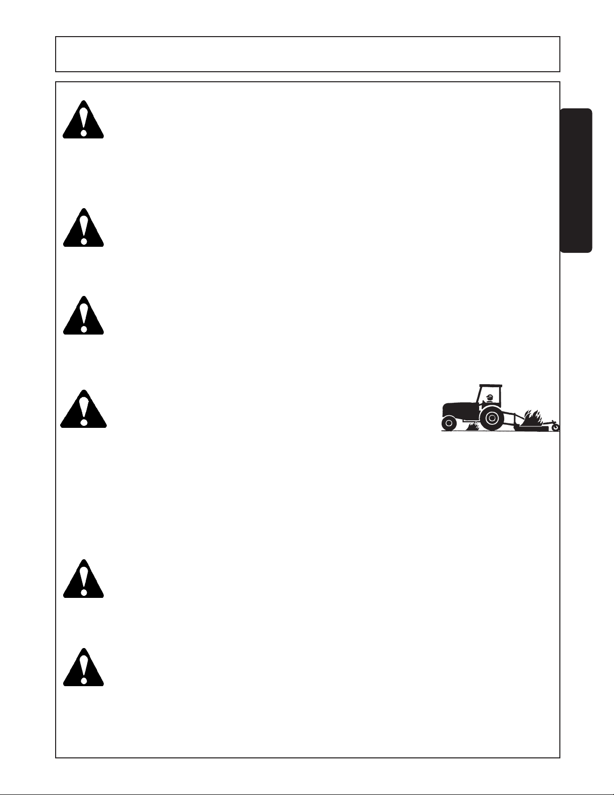
Rotary Mowers are capable under adverse conditions
of throwing objects for great distances (100 yards
or more) and causing serious injury or death. Follow
safety messages carefully
STOP MOWING IF PASSERSBY ARE WITHIN 100 YARDS UNLESS:
-Front and Rear Deflectors, Chain Guards, or Bands are installed
and in good, workable condition;
-Mower sections or Wings are running close to and parallel to the
ground without exposed Blades;
-Passerby are outside the existing thrown-object zone;
-All areas have been thoroughly inspected and all foreign material
such as rocks, cans, glass, and general debris has been removed.
NOTE: Where there are grass and weeds high enough to hide
debris that could be struck by the blades, the area should be:
inspected and large debris removed, mowed at an intermediate
height, inspected, closely with any remaining debris being removed,
and mowed again at desired final height. (This will also reduce
power requiredto mow, reduce wear and tear on the Mower drivetrain,
spread cut material better, eliminate streaking, and make the final
cut more uniform.)
DANGER! Always disconnect the main PTO Driveline from the Tractor before
performing service on the Mower. Never work on the Mower with the
tractor PTO driveline connected and running. Blades or Drivelines
could turn without warning and cause immediate entanglement, injury
or death. (SRM-3)
(SRM-1)
SAFETY
DANGER!
WARNING!
WARNING!
SR15 10/01
© 2004 Alamo Group Inc.
Do not turn so sharp or lift mower so high to produce a severe
"knocking" of the Driveline which will cause accelerated wear and
breakage of drive train components and could result inpossible injury
from the separated Driveline sections. (SRM-4)
Do not let the Blades turn when the Mower Deck is raised for
any reason, including clearance or for turning. Raising the
Mower deck exposes the Cutting Blades which creates a
potentially serious hazard and could cause serious injury or
even death from objects thrown from the Blades. (SRM-7)
Never leave Tractor and Implemented unattended while the implement
is in the lifted position. Accidental operation of lifting lever or a hydraulic
failure may cause sudden drop of unit with injury or death by crushing.
To properly park the implement when disconnecting it from the tractor,
lower the stand and put the retaining pin securely in place, or put a
secure support under the A-Frame. Lower the implement carefully to the
ground. Do not put hands or feet under lifted components. (S3PT-1)
Safety Section 1-9
Page 16
SAFETY
WARNING!
CAUTION!
DANGER!
SAFETY
DANGER!
WARNING!
Use extreme care when lowering or unfolding the implement’s wings.
Make sure no bystanders are close by or underneath the wings. Allow
ample clearance around the implement when folding or unfolding the
wings. Use extreme caution around buildings or overhead power lines.
(S3PT-5)
To prevent tipping of implement when stored in folded position, use
carrying wheels or adequate stands on center frame. (S3PT-6)
There are obvious and hidden potential hazards in the operation of
this Implement as in all power-driven or pulled equipment.
REMEMBER! This machine is often operated in rough terrain conditions
that include tall grass, weeds, gullies, holes, slopes, hidden obstructions
and the like. Serious injury or even death may occur unless care is taken
to assure the safety of the operator and bystanders in the area. Do not
operate this machine with anyone in the immediate area. (S3PT-7)
Make sure the PTO shield, integral driveline shields, and input shields
are is installed when using PTO-driven equipment. Always replace
any shield if it is damaged or missing.
Relieve hydraulic pressure prior to doing any maintenance or repair
work on the Implement. Place the Implement on the ground or securely
blocked up, disengage the PTO, and turn off the tractor engine. Push
and pull the Remote Cylinder lever in and out several times prior to
starting any maintenance or repair work. (S3PT-9)
(S3PT-8)
WARNING!
DANGER!
DANGER!
DANGER!
The rotating parts of this machine continue to rotate even after the PTO
has been turned off. The operator should remain in his seat for 60
seconds after the brake has been set, the PTO disengaged, the tractor
turned off, and all evidence of rotation has ceased. (3PT-10)
“Wait a minute...Save a life!”
Be particularly careful when transporting the Implement using the
tractor. Turn curves or go up or down hills only at a low speed and at a
gradual steering angle. Make certain that at least 20% of the tractor’s
weight is on the front wheels to maintain safe steerage. Slow down on
rough or uneven surfaces. (STI-1)
When the Wings are folded for transport, the center of gravity is raised
and the possibility of overturn is increased. Drive slowly and use
extremecaution when turning on hillsides. Overturning the Implement
could cause the Implement to overturn the Tractor and vice versa
resulting in serious injury or even death. Never fold wings on a
hillside...the Implement may overturn. (STI-2)
DO NOT allow any person under a folded wing unless wing is securely
locked up or supported. DO NOT approach the Implement unless the
Tractor is turned off and all motion has ceased. Never work under the
frame work, or any lifted component unless the implement is securely
supported or blocked up. A sudden or inadvertent fall by any of these
components could cause serious injury or even death. (STI-3)
SR15 10-01
© 2004 Alamo Group Inc.
Safety Section 1-10
Page 17
SAFETY
WARNING!
CAUTION!
WARNING!
WARNING!
Never unhitch without using the Tongue Jack. The Tongue is
very heavy. Attempting to lift the Tongue without using the Tongue
Jack could cause strains or other injury. Allowing the tongue to
fall suddenly and unexpectedly could result in crushing injury.
Use the Tongue Jack for lifting the mower only. Overloading the
Tongue Jack can cause failure with possible serious bodily injury
or even death. (STI-4)
On a fully-assembled unit, do not remove the Wing Retaining Strap
until hoses are attached to the tractor and the Wing Cylinders are
filled with oil. Lower the Wings slowly and carefully. Keep bystanders away during operations.
Only tow the Implement behind a properly sized and equipped Tractor which exceeds the weight
of the Implement by at least 20%. DO NOT tow the Implement behind a truck or other type of
vehicle. Never tow the Implement and another Implement connected in tandem. Never tow the
Implement at speeds over 20 MPH. (STI-6)
Follow these guidelines to reduce the risk of equipment and grass fires
while operating, servicing, and repairing the Mower and T ractor:
-Equip the Tractor with a fire extinguisher in an accesible location.
-Do Not operate the Mower on a Tractor with an underframe exhaust.
-Do Not smoke or have an open flame near the Mower and T ractor .
-Do Not drive into burning debris or freshly burnt areas.
-Ensure slip clutches are properly adjusted to prevent excessive slippage
and plate heating.
-Never allow clippings or debris to collect near drivelines, slip clutches,
and gearboxes. Periodically shut down the Tractor and Mower and clean
clippings and collected debris from the mower deck. (SGM-12)
(STI-5)
SAFETY
WARNING!
DANGER!
SR15 10/01
© 2004 Alamo Group Inc.
Do not mow with two machines in the same area except with Cab tractors with the windows closed.
(SGM-11)
Replace bent or broken blade with new blades. NEVER ATTEMPT TO STRAIGHTEN OR WELD
ON BLADES SINCE THIS WILL LIKELY CRACK OR OTHERWISE DAMAGE THE BLADE
WITH SUBSEQUENT FAILURE AND POSSIBLE SERIOUS INJURY FROM THROWN BLADES.
(SGM-10)
Safety Section 1-11
Page 18

SAFETY
PARTS INFORMATION
Servis-Rhino mowers use balanced and matched system components for blade carriers, blades, cuttershafts,
knives, knife hangers, rollers, drivetrain components, and bearings. These parts are made and tested to
Servis-Rhino specifications. Non-genuine "will fit" parts do not consistently meet these specifications. The
use of “will fit” parts may reduce mower performance, void mower warranties, and present a safety hazard.
Use genuine Servis-Rhino mower parts for economy and safety.
SAFETY
SEE YOUR SERVIS-RHINO DEALER
In addition to the design and configuration of this Implement, including Safety Signs and Safety Equipment,
hazard control and accident prevention are dependent upon the awareness, concern, prudence, and proper
training of personnel involved in the operation, transport, maintenance, and storage of the machine. Refer also
to Safety Messages and operation instruction in each of the appropriate sections of the Tractor and Equipment
Manuals. Pay close attention to the Safety Signs affixed to the Tractor and Equipment. (SG-18)
(SPRM-1)
SR15 10-01
© 2004 Alamo Group Inc.
Safety Section 1-12
Page 19
SAFETY
30
31
13
27
28
31
32
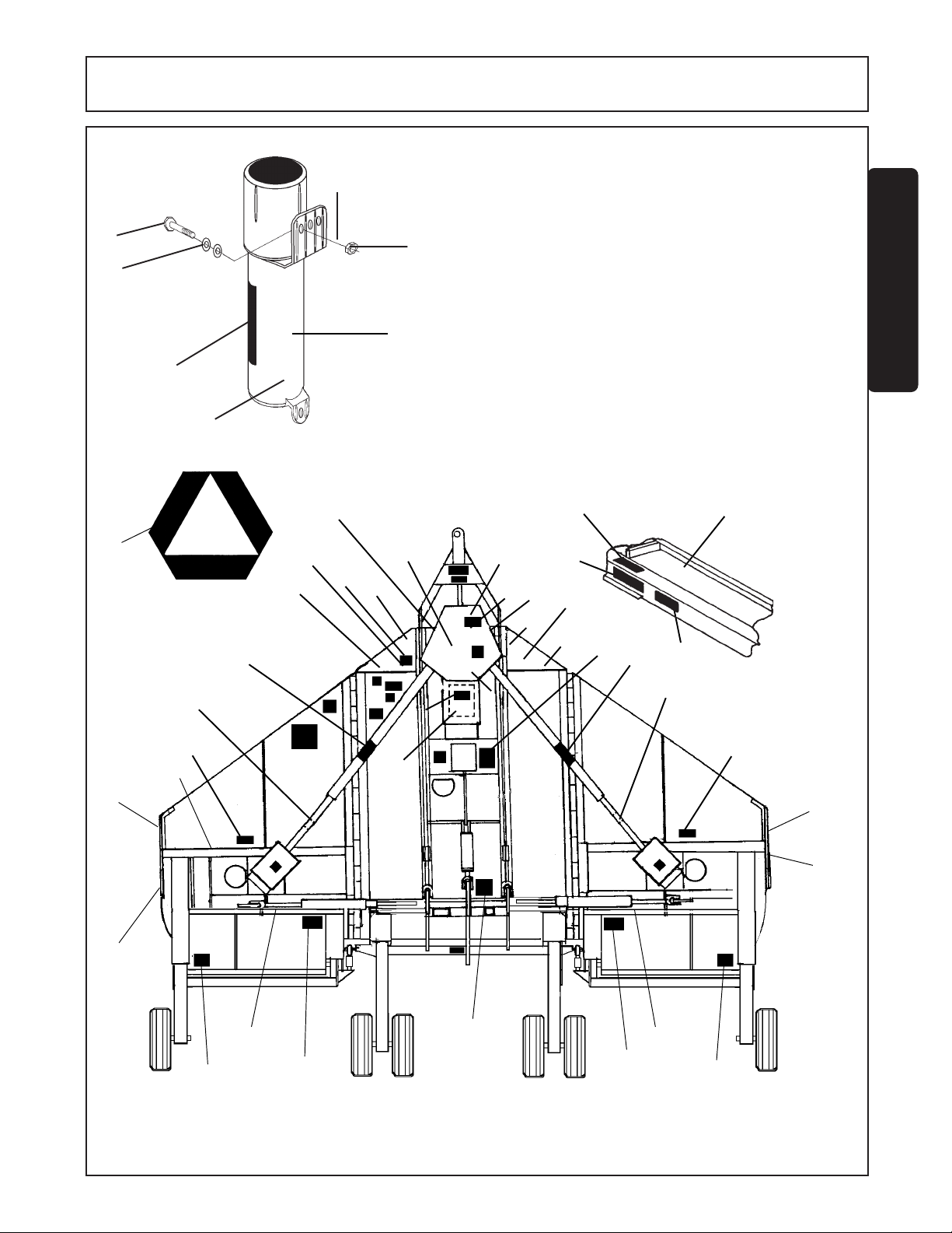
product to promote safe operation. Damage
to the decals may occur while in shipping, use,
or reconditioning. Rhino cares about the
SAFETY
safety of its customers, operators, and
bystanders, and will replace the safety decals
on this product in the field, free of charge
NOTE: Rhino supplies safety decals on this
29
(Some shipping and handling charges may
apply). Contact your Rhino dealer to order
replacement decals.
Counterweight
For two-section
Cutter.
33
21
22
10
11
8
19
24
4
21
12
5
9
4
18
1
17
16
22
24
15
3
20
4
3
14
7
2
26
6
3
19
24
22
14
2
7
SR15 10/01
© 2004 Alamo Group Inc.
Safety Section 1-13
Page 20

SAFETY
SAFETY
ITEM PART NO. QT Y TYPE DECAL DESCRIPTION
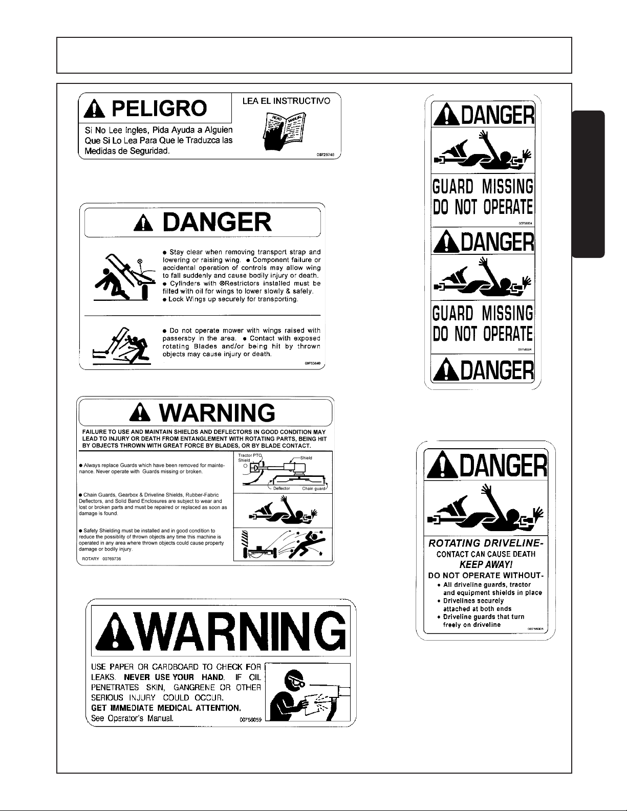
1 00725746 1 PELIGRO Get Manual Translated
2 00753840 2(1) DANGER Folding Wing, Thrown Objects
3 00756004 1((3)) DANGER D/L Shield Missing, Do Not Oper.
4 00756005 1((3)) DANGER Rotating D/L, Entanglement/all shields
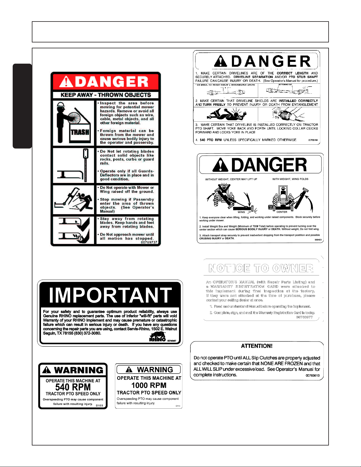
5 00769736 1 WARNING Use/Repair Shields & Guards
6 00756059 1 DANGER Oil Leak Detection
7 00769737 2(1) DANGER Cutting Blades, Thrown Objects
8 00756494 1 DANGER Driveline Multi Hazards
9 00760657 1 IMPORTANT Genuine Rhino Parts
10 00749117 1 DANGER Multiple Hazard, Folding Rotary
11 999403 0(1) DANGER Overturn of Two-section Flex
12 D103 [1] WARNING 540 RPM
D114 [1] WARNING 1000 RPM
13 03200347 *1 REFLECT SMV Emblem
14 1458392 2 REFLECT Red Reflectors
15 1458393 1 REFLECT Amber Reflectors
16 00763613 1 INSTRUCT Slip Clutch Adjustment
17 00763977 1 INSTRUCT Notice To Owner
18 D102 1 INSTRUCT Drbar-to-PTO distance and Safety Chain
19 D137 2 INSTRUCT CCW Blade Rotation
20 D138 1(0) INSTRUCT CW Blade Rotation
21 D302 2 LOGO RHINO (4-7/8 x 6-1/2)
22 D303 2 L.NAME RHINO (4-3/8 x 16-3/4) for RHINO Flexes
23 99101 1 L.NAME RHINO (2 x 7-3/8)
24 00757157 [2] NAME SR15M
00766719 [2] NAME SR10M
25 nfs 1 SER. PLT SR15M
26 00771283 1 INSTRUCT 5-Year Gearbox
00771284 1 INSTRUCT 2-Year Driveline
27 00776481 1 INSTRUCT Operators Manual Inside
28 00776031 1 --------------- Canister, Operators Manual
29 00759799C 1 --------------- Operators Manual
30 10058000 3 --------------- Bolt
31 00024100 6 --------------- Flatwasher
32 02959924 3 --------------- Locknut
33 00773723 1 PELIGRO Rotating Driveline Translation
Decal Sheets
Center Section 00773384
Divider Gearbox 00773388
Right Wing 00773379 SR15
Left Wing 00773378 SR15
Right Wing 00773385 SR10
Weight 00773380 SR10
* Provided by Tractor Manufacturer
( ) For Two-Section Unit Only
(( )) Installed by Driveline Manufacturer
[ ] Use one or the other
SR15 10-01
© 2004 Alamo Group Inc.
Safety Section 1-14
R 04-23-02
Page 21
1 - - 00725746
SAFETY
SAFETY
2 - - 00753840
5 - - 00769736
3 - - 00756004
4 - - 00756005
SR15 10/01
© 2004 Alamo Group Inc.
6 - - 00756059
Safety Section 1-15
R 8-31-92
Page 22
SAFETY
SAFETY
8 - - 00756494
12 - - D103
7 - - 00769737
9 - - 00760657
12 - - D114
11 - - 999403
17 - - 00763977
16 - - 00763613
10 - - 02967827 FRONT COVER
13 - - 03200347 SMV REFLECTOR
14 - - 99203 RED REFLECTOR
15 - - 99204 YELLOW REFLECTOR
SR15 10-01
© 2004 Alamo Group Inc.
Safety Section 1-16
R 04-20-99
Page 23

18 - - D102
SAFETY
SAFETY
26 - - 00771283
22- - D303
21- - D302
23 - - 99101
27 -- 00776481
19 - - D137
24 - - 00757157 NAME (SR 15)
00766719 NAME (SR 10)
25 - - SERIAL PLATE
20 - - D138
SR15 10/01
© 2004 Alamo Group Inc.
Safety Section 1-17
33-- 00773723
R 04-23-02
Page 24

SAFETY
FEDERAL LAWS AND REGULATIONS
This section is intended to explain in broad terms the concept and effect of federal laws and regulations concerning
employer and employee equipment operators. This section is not intended as a legal interpretation of the law
and should not be considered as such.
Employer-Employee Operator Regulations
U.S. Public Law 91-596 (The Williams-Steiger Occupational and Health Act of 1970) OSHA
This Act Seeks:
SAFETY
“...to assure so far as possible every working man and woman in the nation safe and healthful
working conditions and to preserve our human resources...”
DUTIES
Sec. 5 (a) Each employer(1) shall furnish to each of his employees employment and a place of employment which are free
from recognized hazards that are causing or are likely to cause death or serious physical harm to
his employees;
(2) shall comply with occupational safety and health standards promulgated under this Act.
(b) Each employee shall comply with occupational safety and health standards and all rules,
regulations and orders issued pursuant to this Act which are applicable to his own actions
and conduct.
OSHA Regulations
OSHA regulations state in part: “At the time of initial assignment and at least annually thereafter,
the employer shall instruct every employee in the safe operation and servicing of all equipment
with which the employee is, or will be involved.”
Employer Responsibilities:
To ensure employee safety during Tractor and Implement operation, it is the employer’s responsibility to:
1. Train the employee in the proper and safe operation of the Tractor and Implement.
2. Require that the employee read and fully understand the Tractor and Implement Operator’s manual.
3. Permit only qualified and properly trained employees to operate the Tractor and Implement.
4. Maintain the Tractor and Implement in a safe operational condition and maintain all shields and guards on
the equipment.
5. Ensure the Tractor is equipped with a functional ROPS and seat belt and require that the employee operator
securely fasten the safety belt and operate with the ROPS in the raised position at all times.
6. Forbid the employee operator to carry additional riders on the Tractor or Implement.
7. Provide the required tools to maintain the Tractor and Implement in a good safe working condition and
provide the necessary support devices to secure the equipment safely while performing repairs and service.
8. Require that the employee operator stop mowing if bystanders or passerbys come within 100 yards.
Child Labor Under 16 Years of Age
Some regulations specify that no one under the age of 16 may operate power machinery. It is your responsibility
to know what these regulations are in your own area or situation. (Refer to U.S. Dept. of Labor, Employment
Standard Administration, Wage & Home Division, Child Labor Bulletin #102.)
SR15 10-01
© 2004 Alamo Group Inc.
Safety Section 1-18
Page 25
Page 26
Page 27
Page 28
Page 29
Page 30
Page 31

Page 32

Page 33

Page 34

Page 35

Page 36

Page 37

Page 38

Page 39

Page 40

Page 41

Page 42

Page 43

Page 44

Page 45

Page 46

Page 47

Page 48

Page 49

Page 50

Page 51

Page 52

Page 53

Page 54

Page 55

Page 56

Page 57

Page 58

Page 59

Page 60

Page 61

Page 62

Page 63

Page 64

Page 65

Page 66

Page 67

Page 68

Page 69

INTRODUCTION
SECTION
Introduction Section 2-1
Page 70

INTRODUCTION
INTRODUCTION
Your medium-duty Cutter is designed primarily for weed, grass, and brush to 3" diameter. With proper
maintenance as described in this manual, your Cutter will provide you with years of dependable service with a
minimum of repairs.
It is recommended that all operators of this implement read this manual or be instructed of its contents as to
safety, proper operation, and maintenance before beginning operation.
Your Cutter has been assembled for operation with a tractor PTO input speed of either 540 or 1000 RPM.
Should you desire to change PTO input speed, contact your local Rhino dealer who will assist you in performing
the necessary modifications. This machine is recommended for use with tractors rated 50 HP (37kW) to 100
HP (75kW) for 540 RPM drive and 50 HP (37kW) to 140 HP (104kW) for 1000 RPM drive.
When ordering parts for the Gearboxes and the Drivelines, be sure to specify the serial number. The serial
number is located outside of the right Tongue attaching Plate on the center Mainframe section.
Chain Guards are extra equipment. Deflectors, Driveline Integral Shields, and Gearbox Shields are standard
equipment and are to be used at all times.
To place the warranty into effect, fill out the warranty card in full, giving all the requested information, and mail
promptly. Be sure to give the serial number of this Cutter.
SR15 10-01
© 2004 Alamo Group Inc.
Introduction Section 2-2
Page 71

ASSEMBLY
SECTION
Assembly Section 3-1
Page 72

ASSEMBLY
Set up mower as received from factory with these instructions. Refer to Parts Listing Section for further
information when necessary.
Select a suitable working area. Open parts box and lay out parts to make location easy. Refer to parts listing
and exploded view drawings in the Parts Listing Section and the packing list.
Cut all wire ties, including those on blades if present.
This mower is shipped partially assembled. Assembly will be easier if components are aligned and loosely
assembled before tightening hardware. Refer to Torque Chart when tightening hardware.
Position Center Section on a flat surface. Elevate approximately 10 inches from ground to permit the installation
of Wing Sections.
BLADE CARRIER AND BLADES
The Frame sections are shipped from the factory without the Blades attached to the Blade Carrier. Optional
Straight or Fan Blades are available.
WARNING Do not install Blades or do any work under the Cutter sections unless the section(s) are
safely and securely blocked or latched in place.
The Blade Bolts must be tightened to 250 ft. lbs. torque before operating. NOTE: Blade Bolts have left-hand
ASSEMBLY
threads.
To insure proper installation, check to see that Blade cutting surfaces are correct for counterclockwise rotation
on the Center Section and on the Right Wing Blade Carrier. FIGURE 1. (Clockwise on Left Wing)
Blade Carrier
Left Wing Shown
NOTE: Cutting Edge
for Clockwise Rotation
FIGURE 1
SR10M/SR15M 10-01
© 2004 Alamo Group Inc.
FIGURE 1
Assembly Section 3-2
Page 73

ASSEMBLY
TONGUE ATTACHMENT
Long Tongue FIGURE A
To assemble the long tongue. Align the lugs of the tongue with the top holes of the mainframe hitch plate (1).
Insert the pivot pin (2) and fasten with 2 - 3/8" x 1 1/4" bolt (3) and 3/8" locknut (4). To assemble the control rod
install a jam nut onto the short rod (5), then thread the short rod (5) into the long rod (6). Align the hole of the
short control rod (5) to the top hole of the center lug on the mainframe (7). Insert pin and lock with cotter pins.
Align the hole of the long rod (6) to the clevis hitch (8) and insert pin with cotter pin (9).
Short Tongue FIGURE B
To assemble the short tongue align the tongue with the lower holes of the mainframe hitch plate (10). Insert the
pivot pin (11) and fasten with 2 - 3/8" x 1 1/4" bolts (12) and 3/8" locknut (13). Align the control rod (14) to the
lower hole of the center lug on the mainframe (15). To attach the control rod follow the same procedure as
stated in the long tongue.
Short Tongue
Assembly
10
10
15
1
11,12,13
14
8
FIGURE B
CENTER AXLE ATTACHMENT- LEVEL LIFT & NON LEVEL LIFT
6
9
FIGURE A
ASSEMBLY
Long Tongue
Assembly
7
2,3,4
5
Install Center Axle (1) to lugs (2) at rear of Center Section with (2) 1" x 7" lg. bolts (3), and locknuts (4). Figure 2.
4
2
SR10M/SR15M 10-01
© 2004 Alamo Group Inc.
1
FIGURE 2. Axle Attachment
Assembly Section 3-3
3
Page 74

ASSEMBLY
LEVEL ROD ASSEMBLY
Slide Long Level Rods (1) through Center Section frame channel and attach to Tongue with Level Rod Pins (2),
washers (3), and cotter pins (4). FIGURE 3. Attach Jam Nuts (5) and Adjusting Nuts (6) to the Long Level Rods.
Install Short Level Rods to Adjusting Nuts. Measure and adjust to the same length. Then attach the Short Level
Rods to the Rear Axle with Level Rod Pins, washers, and cotter pins. Figure 4.
1
4
2
ASSEMBLY
FIGURE 3. Long Level Rod Attachment to Tongue.
TONGUE CLEVIS LEVELING
Tongue Clevis is leveled with Control Rod under Tongue. With Tongue, all Control Rod, Rear Axles and all other
components assembled to Main Frame, Set Jack under Drawbar Clevis and exert enough lift on Clevis to hold
it up and pull all slack out of Tongue Control Rod. Adjust Control Rod for length to raise or lower Clevis as
required until it is parallel and will sit level on Tractor Drawbar. This Adjustment will keep Clevis level as mower
is raised and lowered as long as weight of mower is resting on Clevis, and all components are in good condition.
DRAWBAR CLEVIS
3
FIGURE 4. Short Level Rod Attachment To Axle.
TONGUE HITCH CONTROL ROD
6
5
SR10M/SR15M 10-01
© 2004 Alamo Group Inc.
Assembly Section 3-4
Page 75

ASSEMBLY
WING SECTIONS ATTACHMENTS
While the Center Section is still solidly blocked, attach the Wing Sections (1) in the horizontal plane. Using
Hinge Pins (2), attach the Right and Left Wing Sections to the Center Sections.
NOTE: Wing Sections may require slight lifting after the Hinge Pin is started to aid pin installation.
Lock the Wing Sections in place with the Hinge Pins. Insert 5/16 x 1-1/2 bolt (3) and locknut (4) at the end of
each of the Hinge Pins and tighten securely. FIGURE 5.
FIGURE 5. Wing Sections Attachments
ASSEMBLY
WING AXLE ATTACHMENT- MECHANICAL LEVEL LIFT
Attach the Wing Axles (1) to the Wing Sections (2) with 1 x 7 bolts (3), flatwashers (4), and locknuts (5) on
outboard side and 1 x 4-3/4 bolt (6), and locknuts (5) on the inboard side. FIGURE 6.
2
6
3
1
5
R 11-11-99
SR10M/SR15M 10-01
© 2004 Alamo Group Inc.
5
FIGURE 6. Wing Axle Attachment
Assembly Section 3-5
Page 76

ASSEMBLY
AXLE ADJUSTMENT ROD ATTACHMENT
Attach the Axle Adjustment Rod w/Bushings (1) to
the Center Axle and Wing Axle with bolts and
locknuts. FIGURE 7.
1
FIGURE 7. Axle Adjustment Rod Attachment
TIRES AND WHEELS
Before installing any tires and wheels make certain the Cutter is jacked up high enough and is securely
supported. When installing laminated or airplane tires, be sure the flat side of the lug nut is against the
Wheel. There are only three types of tires that can be used on this cutter DO NOT USE ANY OTHER TYPE
OF TIRE OR WHEEL, such as automotive tires and rims. DO NOT EXCEED THE MAXIMUM SPEED FOR
EACH TYPE OF TIRE. As excessive speed can cause damage to the machine, tire, and wheel.
ASSEMBLY
When installing Sectional Tires and Wheels note the direction of travel and the curvature of rubber
segments in the tire and install as shown in FIGURE 8. Do not exceed 15 M.P.H. on Sectional Tires. When
removing Airplane Tires, let all of the air out of the tire before removing lug nuts or wheel bolts or nuts.
Remove valve core to make certain that there is no air pressure left in tube before seperating wheel halves
to dismount tires. DO NOT LOOSEN WHELL CLAMP BOLTS BEFORE PRESSURE IS REMOVED FROM
TUBE AND TIRE TO PREVENT EXPLOSIVE SEPERATION OF WHEEL HALVES WITH POSSIBLE
SERIOUS BODILY INJURY. Do not exceed 20 M.P.H. on Airplane or Rib Implement Tires.
Maximum airplane tire inflation pressure is 50 PSI, minimum inflation pressure is 20 PSI. Inflate ribbed
implement tires to manufacturer rated PSI as shown on the tire sidewall.
SR10M/SR15M 10-01
© 2004 Alamo Group Inc.
Assembly Section 3-6
Page 77

ASSEMBLY
ASSEMBLY
SR10M/SR15M 10-01
© 2004 Alamo Group Inc.
FIGURE 8. Wheel Attachment
Decal for Airplane tire Only.
Assembly Section 3-7
Page 78

ASSEMBLY
SPRING ASSEMBLY ATTACHMENT
Attach the Spring Assembly (1) to the Center Section Lug with pin (2) and cotter pin. FIGURE 10.
1
2
ASSEMBLY
CENTER AXLE HYDRAULIC CYLINDER ATTACHMENT
Install the clevis rod of the 8" stroke Hydraulic Cylinder to the lug on the Center Axle. The clevis base fastens
to the lug or Spring Assembly on the Center Section. FIGURE 11.
FIGURE 10. Spring Assembly Attachment
SR10M/SR15M 10-01
© 2004 Alamo Group Inc.
FIGURE 11. Center Axle Hydraulic Cylinder Attachment
Assembly Section 3-8
Page 79

ASSEMBLY
WING SECTION HYDRAULIC CYLINDER ATTACHMENT
Mount the 14" stroke Hydraulic Cylinder butt clevis to the upright lugs on the Center Section and the rod end to
lugs on wing. Make sure the ports of the Hydraulic Cylinder are facing upwards. Keep the ports capped until the
hoses are attached to the tractor and are ready to attach to the cylinder ports. FIGURE 12. Install the Transport
Bars to retain the Wing Sections in the upright position for transport on roads and highways. When in transport
keep the Center Section as low to the ground as possible to increase stability but high enough to prevent the
Skid Shoes from dragging.
Wing Hydraulic
Cylinder
Transport BarOperating Position
ASSEMBLY
FIGURE 12. Wing Section Hydraulic Cylinder Attachment.
COUNTERWEIGHT BOX ATTACHMENT ON TWO SECTION UNITS
Keep everyone clear when lifting, and working under raised components. Block securely before working
under mower. Install Weight Box and Weight (Minimum of 700# Total) before operating to prevent turning
over the center section which can cause SERIOUS BODILY INJURY or DEATH. Without weight. Do not fold
wing. Attach transport strap securely to prevent inadvertent dropping from the transport position and possible
CRUSHING INJURY or DEATH.
SR10M/SR15M 10-01
© 2004 Alamo Group Inc.
Assembly Section 3-9
Page 80

ASSEMBLY
HOSE BRACKET ATTACHMENT
Hose Brackets are attached in the front and rear of the mower. The Front Hose Bracket bolts to the tongue lug
brackets. The Rear Hose Bracket mounts to the center hydraulic suspension spring bracket. FIGURE 13.
FIGURE 13. Hose Bracket Attachment
CHAINGUARDS (EXTRA) OR RUBBER DEFLECTORS (STANDARD)
ASSEMBLY
Fasten the front Chainguards or Rubber Deflector
(Figure 14) to the Center Section and Wing Sections
with bolts (1) and locknuts (3) through the deflector
bracket (#2).
Fasten the rear Chainguards (Figure 15) or Rubber
Deflector to the Center Section and Wing Sections
with bolts (1) and locknuts (3).
3
1
3
2
1
FIGURE 14. Front Deflectors (Standard)
3
1
REAR CENTER SECTION REAR RIGHT WING SECTION
SR10M/SR15M 10-01
© 2004 Alamo Group Inc.
FIGURE 15. Rear Chainguards Attachment (Extra)
Assembly Section 3-10
Page 81

ASSEMBLY
DRIVELINE ATTACHMENT
Remove Divider Gearbox Shield if installed. Remove any tape from Gearbox shafts. Attach the Slipclutch end
of the Wing Driveline to the Divider Gearbox. Attach the clamp collar end of Driveline to Wing Gearbox. Tighten
bolts evenly to their proper torque. FIGURE 16 & FIGURE 17. Install the Main Driveline with clamp collar to the
Divider Gearbox .
WING DRIVELINE
SLIP CLUTCH END
NOTE: Divider Gearbox Shield must be
in place to guard connecting yokes and
clutches.
FIGURE 16. Wing Driveline Clutch End Attachment
NOTE: Wing Gearbox Shield must
be in place and lowered to guard
connecting yokes and clutches.
DIVIDER GEARBOX
ASSEMBLY
MAIN DRIVELINE
SR10M/SR15M 10-01
© 2004 Alamo Group Inc.
WING DRIVELINE
CLAMP COLLAR END
FIGURE 17. Wing Driveline Clamp Collar End Attachment
Assembly Section 3-11
Page 82

ASSEMBLY
DRIVELINE CLAMP CONE YOKE OPERATING
INSTRUCTIONS
Loosen the yoke clamp cone with a 11/16” (17mm) wrench and
remove the cone from yoke. Slide yoke onto the shaft and
align hole for clamping cone with annular groove of gearbox
shaft. Reinstall cone and tighten (75 lb-ft torque). Push and pull
the driveline to ensure it is securely attached to the shaft.
Regularly check the driveline yoke to ensure a tight connection.
To remove the yoke, remove the connecting cone and pull yoke
off the shaft. If the cone cannot be easily removed by hand,
drive it out from the other side using a hammer and punch.
NOTE: The clamping cone is serviced only as a complete
assembly. Do not attempt to disassemble the clamping cone.
EQUAL ANGLE JACKSHAFT DRIVELINE
10
ASSEMBLY
12
11/16" Bolt End
Clamping Cone
3
5
Driveline Yoke
MOUNT IN THIS HOLE FOR 1000
MOUNT IN THIS HOLE FOR 540
4
8,9
1
2
11
13
6,7
Attach bearingsupport weldment (ref #1) to torque weldment as shown. Install jackshaft bearing (ref #2) onto
jackshaft stub end.
SR10M/SR15M 10-01
Assembly Section 3-12
R 12-06-01
© 2004 Alamo Group Inc.
Page 83

ASSEMBLY
(540 RPM 1-3/8"-6)
(1000 RPM 1-3/8"-21)
ASSEMBLY
WINCH ASSEMBLY ATTACHMENT (OPTIONAL EQUIPMENT)
Attach the Winch Stand to the cross bar on the Center Section with bolts and locknuts. Attach the Winch to the
Winch Stand with bolts and locknuts. See Operation Section for use.
THREE SPOOL CONTROL VALVE INSTALLATION
A Three-Spool Control Valve is available from your dealer for use with tractors having either an open or closed
center Hydraulic System. If a 3 spool valve bank is required assemble on bracket and install on tractor fender at
desired location. Refer to Parts List Section. To install the hydraulics from the Mower to the Control Valve,
connect the Center Axle Lift Cylinder Hose to the Right Port on the Hydraulic Valve. Connect the Wing Folding
Cylinder Hoses to the same side of the Control Valve as the Cylinder are on the Mower rather than crossing the
Hoses. Route hoses through front and rear hose brackets. Remove plastic plug from Breather of Cylinder
before operation.
3-Spool Control Valve
SR10M/SR15M 10-01
© 2004 Alamo Group Inc.
Assembly Section 3-13
Page 84

Page 85

OPERATION
SECTION
Operation Section 4-1
Page 86

OPERATION
RHINO SR10/SR15 ROTARY MOWER
OPERATION INSTRUCTIONS
Rhino SR10/SR15 rotary mowers are manufactured with quality material by skilled workers. These mowers are
designed to cut grass, weeds, crop stalks, small brush and other vegetative material up to 3” diameter . The mower
is equipped with protective deflectors and/or chain guards to prevent objects being thrown from the mower by the
blades, however, no shielding is 100% ef fective. All shields, guards, deflectors, and chains equipped on the unit
must be maintained on the mower in good operational condition.
It is the operator’s responsibility to be knowledgeable of all potential operating hazards and to take every reasonable
precaution to ensure oneself, others, animals, and property are not injured or damaged by the mower, tractor , or a
thrown object. Do not operate the mower if passersby , pets, livestock, or property are within 300 feet of the unit.
This section of the Operator’s Manual is designed to familiarize, instruct, and educate safe and proper mower use
to the operator. Pictures cont ained in this section are intended to be used as a visual aid to assist in explaining
the operation of a flex-wing rotary mower and are not necessarily of a SR10/SR15 cutter. Some pictures may
show shields removed for picture clarity. NEVER OPERATE this implement without all shields in place and in
good operational condition. The operator must be familiar with the mower and tractor operation and all associated
safety practices before operating the mower and tractor. Proper operation of the mower, as detailed in this
manual, will help ensure years of safe and satisfactory use of the mower.
IMPORTANT: To avoid mower damage, retorque all bolts after the first 10 hours of operation. Retighten blade
carrier retaining nut on gearbox lower shafts to 450 ft. lbs..
MOWER STANDARD EQUIPMENT AND SPECIFICATIONS.................................................................4-4
(1) OPERATOR REQUIREMENTS....................................................................................................4-5
(2) TRACTOR REQUIREMENTS.......................................................................................................4-6
(2.1) ROPS and Seatbelt............................................................................................................4-6
(2.2) Tractor Safety Devices.......................................................................................................4-6
(2.3) Tractor Horsepower............................................................................................................4-6
(2.4) Drawbar............................................................................................................................4-7
OPERATION
(2.5) Tractor Hydraulics.............................................................................................................4-8
(2.6) Front End Weight...............................................................................................................4-8
(2.7) Power Take Off (PTO).........................................................................................................4-8
(2.8) Tire Spacing......................................................................................................................4-9
(3) GETTING ON AND OFF THE TRACTOR........................................................................................4-9
(3.1) Boarding the Tractor...........................................................................................................4-9
(3.2) Dismounting the Tractor......................................................................................................4-9
(4) STARTING THE TRACTOR.........................................................................................................4-10
(5) CONNECTING THE MOWER T O THE TRACTOR..........................................................................4-11
(5.1) Connecting the Mower Tongue to the Tractor........................................................................4-11
(5.2) Connecting Mower Hydraulic Lines to the Tractor..................................................................4-12
(6) SETTING THE MOWER.............................................................................................................4-13
(6.1) Setting Deck Height..........................................................................................................4-13
(6.2) Setting Deck Pitch............................................................................................................4-14
SR10M/SR15M 10-01
© 2004 Alamo Group Inc.
Operation Section 4-2
R 09-16-02
Page 87

OPERATION
(7) DRIVELINE ATTACHMENT..........................................................................................................4-14
(7.1) Driveline Length Check......................................................................................................4-15
(7.2) Constant Velocity (CV) Driveline.........................................................................................4-17
(8) PRE-OPERATION INSPECTION AND SERVICE.........................................................................4-18
(8.1) Tractor Pre-Operation Inspection/Service.............................................................................4-19
(8.2) Mower Pre-Operation Inspection/Service.............................................................................4-19
(9) DRIVING THE TRACTOR AND MOWER......................................................................................4-22
(9.1) Starting the Tractor............................................................................................................4-23
(9.2) Brake and Differential Lock Setting.....................................................................................4-23
(9.3) Operating the Mower Wings...............................................................................................4-24
(9.4) Driving the Tractor and Mower.............................................................................................4-25
(9.5) Crossing Ditches and Steep Inclines...................................................................................4-26
(10) OPERATING THE TRACTOR AND MOWER...............................................................................4-27
(10.1) Foreign Debris Hazards...................................................................................................4-27
(10.2) Bystander/Passersby Precaution......................................................................................4-28
(10.3) Engaging the Power Take Off (PTO)........................................................................................4-29
(10.4) PTO RPM and Ground Speed...........................................................................................4-29
(10.5) Operating the Mower........................................................................................................4-30
(10.6) Shutting Down the Mower................................................................................................4-33
(1 1) DISCONNECTING THE MOWER FROM THE TRACT OR...........................................................4-34
(12) MOWER STORAGE.................................................................................................................4-35
(13) TRANSPORTING THE TRACTOR AND MOWER......................................................................4-36
(13.1) Transporting on Public Roadways....................................................................................4-38
(13.2) Hauling the Tractor and Mower..........................................................................................4-40
(14) TROUBLE SHOOTING GUIDE..................................................................................................4-41
READ AND UNDERSTAND THE ENTIRE OPERATING INSTRUCTIONS AND SAFETY SECTION OF THIS
MANUAL AND THE TRACTOR MANUAL BEFORE ATTEMPTING TO USE THE TRACTOR AND MOWER.
If you do not understand any of the instructions, contact your nearest authorized dealer for a full explanation.
Pay close attention to all safety signs and safety messages contained in this manual and those affixed to the
cutter and tractor.
DANGER!
READ, UNDERSTAND, and FOLLOW the following Safety Messages. Serious
injury or death may occur unless care is taken to follow the warnings and
instructions stated in the Safety Messages. Always use good common sense
to avoid hazards. (SG-2)
OPERATION
PELIGRO!
Si no lee Ingles, pida ayuda a alguien que si lo lea para que le traduzca las
medias de seguridad. (SG-3)
SR10M/SR15M 10-01
© 2004 Alamo Group Inc.
!LEA EL
INSTRUCTIVO!
Operation Section 4-3
Page 88

Horsepower Required (Min.).......50 HP 40 HP
Cutting Capacity (Diameter)....... 3” 3”
Cutting Height............................1”-15” 1”-15”
Safety Deflectors*.......................Standard Standard
Cutting Width............................ 180” 126”
Transport Width.........................90-1/2” 88”
Overall Width.............................186” 133”
Overall Length............................183” 183”
Blade Overlap.............................6” 6”
Weight (Approximate)................ 4345 lbs. 3910 lbs.
Wing Lift....................................Hydraulic Hydraulic
Wing Flex (Degrees).................. 90° Up-22° Down 90° Up-22° Down
Jack Stand............................... Standard Standard
Hitch........................................ Heavy-Duty Clevis Heavy-Duty Clevis
Blade Carrier..............................Pan Pan
Gearbox Rating:**
Power Divider.......................180 HP 180 HP
Center & Wings...................140 HP 140 HP
Output Shaft Diameter............... 2-3/8” 2-3/8”
Blade Tip Speed
Center 540 RPM................ 14,861 FPM 14,861 FPM
Wings 540 RPM.................14,242 FPM 14,242 FPM
Driveline Size:
Main (44R or CV)................ Cat 5 Cat 5
OPERATION
Wings................................ Cat 4 or 5 Cat 4 or 5
Deck Thickness........................ 10 Gauge 10 Gauge
Side Skirts............................... 1/4”x10-1/2” 1/4”x10-1/2”
Replaceable Skid Shoes............ Standard Standard
OPERATION
Standard Equipment and Specifications
SR15 SR10
1000 RPM................15,570 FPM 15,570 FPM
1000 RPM...............14,624 FPM 14,624 FPM
*Safety Deflectors are standard equipment. Single and double chain guards are available
as extra equipment at extra cost. Servis-Rhino recommends mowers be equipped with
deflectors or double chain guards for all mowing purposes. Single chain guards may be
used for agriculture purposes only and are specifically not recommended for highway,
right-of-way, parks or greenbelt mowing.
**Ratings based on actual field performance.
SR10M/SR15M 10-01
© 2004 Alamo Group Inc.
Operation Section 4-4
Page 89

OPERATION
1. OPERATOR REQUIREMENTS
Safe operation of the rotary mower is the responsibility of a qualified operator. A qualified operator has read and
understands both the mower and tractor Operator Manuals and is experienced in tractor and mower operations
and all associated safety practices. In addition to the safety messages contained in this manual, safety message
decals are affixed to the mower and tractor. If any part of the operation and safe use of the mower and tractor is
not completely understood, consult an authorized dealer for a full explanation.
Safe mower operation requires that the operator wear approved Personal Protective Equipment (PPE) for the
job conditions while connecting, operating, servicing and repairing the mower and tractor. PPE is designed to
provide operator protection from bodily injury and includes the following:
Personal Protective Equipment (PPE)
Protective eye glasses, goggles, or face shield
Hard hat
Steel toed safety footwear
Gloves
Hearing protection
Close fitting clothing
Respirator or filter mask
OPERATION
DANGER!
SR10M/SR15M 10-01
© 2004 Alamo Group Inc.
NEVER use drugs or alcohol immediately before or while operating
the Tractor and Implement. Drugs and alcohol will affect an
operator’s alertness and coordination and therefore affect the
operator’s ability to operate the Equipment safely. Before
operating the Tractor or Implement, an operator on prescription
or over-the-counter medication must consult a medical
professional regarding any side effects of the medication that
would hinder their ability to operate the Equipment safely. NEVER
knowingly allow anyone to operate this Equipment when their
alertness or coordination is impaired. Serious injury or death to
the operator or others could result if the operator is under the
influence of drugs or alcohol. (SG-27)
Operation Section 4-5
Page 90

OPERATION
2. TRACTOR REQUIREMENTS
The tractor used to operate the mower must have the power capacity to lift, pull, and operate the Power Take Off
(PTO) at the mower’s rated speed while traveling at a ground speed between 2 and 5 MPH. Operating the
mower with a tractor that does not meet the following requirements may cause tractor or mower damage and be
a potential danger to the operator and passersby.
Tractor Requirements and Capabilities
ASAE approved Roll-Over Protective Structure (ROPS) or ROPS cab and seat belt.
Tractor Safety Devices...........................……… Slow Moving Vehicle (SMV) emblem, lighting,
PTO master shield
Tractor Horsepower -Minimum .........................SR10 40 HP; SR15 50 HP
-Maximum…….................. 540 RPM Unit - 100 HP; 1000 RPM Unit 140 HP
Drawbar......................................................... Set length according to operating speed of the mower and
driveline type, rated to carry weight of the mower,
safety chain attachment point
Hydraulics...................................................... Minimum of 1 hydraulic port (extra 3-spool valve required).
Minimum 2 ports, 3 ports recommended if additional
3-spool control valve is not used.
Front End Weights..…………........................... As needed to maintain 20% weight on front axle
Power Take Off.....................…….................... Operating speed and shaft size depends on operating speed
and driveline type of the mower.
Tire Wheel Spacing..............…….................... Set tires minimum width of 60” from inside to inside of tires.
2.1 ROPS and Seat Belt
A Roll-Over-Protective-Structure (ROPS) and seat belt are essential to protect the operator from falling off the
tractor, especially during a roll over where the driver could be crushed and killed. The ROPS and seat belt must
be used in conjunction with one another. Only operate the tractor with the ROPS in the raised position and seat
belt fastened. Tractor models not equipped with a ROPS and seat belt should have these life saving features
installed by an authorized tractor dealer.
WARNING!
OPERATION
Operate this Equipment only with a Tractor equipped with an approved roll-overprotective system (ROPS). Always wear seat belts. Serious injury or even death
could result from falling off the Tractor--particularly during a turnover when the
operator could be pinned under the ROPS. (SG-7)
2.2 Tractor Safety Devices
If transporting or operating the tractor and mower near a public roadway, the tractor must be equipped with
proper warning lighting and a Slow Moving Vehicle (SMV) emblem which are clearly visible from the rear of the
unit. Lights and a SMV emblem must be equipped directly on implements if the visibility of the tractor warning
signals are obscured.
Maintain all manufacturer equipped safety shields and guards. Always replace shields and guards that were
removed for access to connect, service, or repair the tractor or mower. Never operate the tractor PTO with the
PTO master shield missing or in the raised position.
2.3 Tractor Horsepower
The horsepower required to operate the mower depends on several operating factors including the vegetation to
be cut, terrain condition, operator experience, condition of the mower and tractor, and others. For most mowing
conditions, the SR10 mower requires a tractor with a minimum of 40 HP and the SR15 mower requires a tractor
with a minimum of 50 HP. Operating the mower with a tractor that does not have adequate power may damage
the tractor engine. Exceeding 100 HP for a 540 RPM drive and 140 HP for a 1000 RPM drive may cause mower
damage by overpowering the unit in heavy cutting conditions.
SR10M/SR15M 10-01
© 2004 Alamo Group Inc.
Operation Section 4-6
Page 91

OPERATION
2.4 Drawbar
Constant Velocity and Standard Driveline
Position the length of the drawbar from the end of the
tractor PTO shaft to the drawbar hitch hole according
to the operating speed of the mower. If the mower is
a 540 RPM unit, position the drawbar length from shaft
end to hitch hole at 14”. For 1000 RPM mowers, set
the drawbar length at 16” for 21 spline 1-3/8” mowers
and at 20” for 1-3/4” 20 spline mowers.
Equal Angle Driveline Adjustment Procedure
(Not available on 1000 RPM 1-3/4”-20 mowers)
Set drawbar length measured from PTO shaft end to hitch hole at 14” for 540 and 16” for
1000 RPM operating speeds. Position carrier bearing to align driveline in as straight of line as possible. Make
certain that the Yokes on the Driveline and the Equal Angle Jackshaft are aligned with each other, otherwise the
drivelines will not phase properly, possibly causing damage to your machine.
Tractor Drawbar Length
(Based on Mower Operating Speed)
14" (540 RPM 1-3/8”-6)
TONGUE
16" (1000 RPM 1-3/8”-21)
20” (1000 RPM 1-3/4”-20)
DRAWBAR
Pintle Hook Hitch-Optional Equipment
Drawbar length must be modified to obtain dimension
"A" (CV Driveline = 17" ± 2", Standard Driveline = 19”
± 2" ).
Tongue
(540 RPM 1-3/8"-6)
(1000 RPM 1-3/8"-21)
OPERATION
PTO
Shaft
A
Drawbar
SR10M/SR15M 10-01
© 2004 Alamo Group Inc.
Operation Section 4-7
Tongue
Cont. Rod
Pintle
Clevis
Pintle
Hook
Pintle Hook
Mount
Page 92

OPERATION
2.5 Tractor Hydraulics
The mower center section and each wing are positioned with hydraulic cylinders that are operated by the tractor
hydraulic pump. The tractor must have a minimum of 2 hydraulic control valves devoted to the mower unless
the tractor is fitted with a 3-spool control valve (extra equipment).
A 3-spool control valve is required if the tractor is equipped with a single valve and is recommended for those
with two valves so that the center section and each wing can be controlled independent of one another. Refer
to the Assembly Section of this manual for properly equipping the tractor with a 3-spool control valve. Tractors
equipped with three hydraulic ports can position the center section and each wing independently with no extra
equipment. If the tractor is equipped with only two hydraulic ports and a 3-spool control valve is not used, the
wings cannot be operated independently and will raise and lower at different speeds.
2.6 Front End Weight
A minimum of 20% total tractor weight must be maintained on the tractor front end at all times. Front end weight
is critical to maintain steering control and to prevent the tractor from rearing up while driving. If the front end is
too light, add weight until a minimum of 20% total weight is reached on the front tires. Front weights and weight
carriers can be purchased through an authorized tractor dealership.
2.7 Power Take Off (PTO)
Depending on the unit, the mower is designed to operate at a PTO speed of 540 or 1000 RPM. Most tractors
operate at either 540, or a combination of 540 and 1000 RPM PTO speeds. The operating speed of the mower
and tractor can be determined by the number of splines on the driveline yoke and PTO output shaft. Those
operating at 540 RPM will have a 1-3/8” diameter 6-spline shaft and those operating at 1000 RPM will have a 13/8” 21-spline shaft or a 1-3/4” 20 spline shaft. Refer to the tractor owner’s manual for instructions to change
PTO speeds on models that operate at more than one speed.
OPERATION
If operating an older model tractor where the tractor’s transmission and PTO utilize one master clutch, an overrunning clutch must be used between the PTO output shaft and the driveline of the mower. An authorized tractor
dealer can provide the over-running clutch and its installation if needed.
WARNING!
WARNING!
DO NOT use a PTO adapter to attach a non-matching Implement driveline to a Tractor PTO.
Use of an adapter can double the operating speed of the Mower resulting in excessive
vibration, thrown objects, and blade and mower failure. Adapter use will also change the
working length of the driveline exposing unshielded driveline areas. Serious bodily injury
and/or equipment failure can result from using a PTO adapter. Consult an authorized dealer
for assistance if the Implement driveline does not match the Tractor PTO.
(S3PT-14)
Never operate the Tractor and Mower if the Mower main driveline is directly connected to
the Tractor transmission. Tractor braking distances can be substantially increased by the
momentum of the rotating Mower blades driving the Tractor transmission even though the
Tractor clutch has been engaged. Install an over running clutch between the Tractor PTO
and the Mower driveline to prevent this potentially dangerous situation.
SR10M/SR15M 10-01
© 2004 Alamo Group Inc.
Operation Section 4-8
Page 93

OPERATION
2.8 Tire Spacing
Tractor tires should be set a minimum of 60” apart
measured from inside of tire to inside of tire. Refer to
the tractor Operator’s Manual or consult an authorized
dealer for instructions to change tractor tire spacing.
Tire Spacing
Minimum Width 60”
3. GETTING ON AND OFF THE TRACTOR
Before getting onto the tractor, the operator must read and completely understand the mower and tractor operator
manuals. If any part of either manual is not completely understood, consult an authorized dealer for a complete
explanation.
WARNING!
Do not mount the Tractor while the tractor is moving. Mount the
Tractor only when the Tractor and all moving parts are completely
stopped. (SG-12)
3.1 Boarding the Tractor
Use both hands and equipped handrails and steps for support when getting on the tractor. Never use tractor
control levers for support when mounting the tractor. Always seat yourself in the operator’s seat and fasten the
seatbelt. Only operate the tractor and mower with the ROPS in the raised position.
Never allow passengers to ride on the tractor or mower. Riders can easily fall off and be seriously injured or
killed from being ran over by both the tractor and mower. It is the operator’s responsibility to forbid riders.
DANGER!
DANGER!
Never allow children or other persons to ride on the Tractor or Implement.
Falling off can result in serious injury or death. (SG-10)
Never allow children to operate or ride on the Tractor or Implement.
(SG-11)
OPERATION
3.2 Dismounting the Tractor
Before dismounting, park the tractor and mower on a reasonably level surface, apply the parking brake, idle the
engine down, disengage the PTO, and lower the mower to the ground. Shut down the tractor engine according
to the operator’s manual, remove the key, and wait for all motion to completely stop. Never leave the seat until
the tractor, its engine and all moving mower parts are completely stopped.
SR10M/SR15M 10-01
© 2004 Alamo Group Inc.
Operation Section 4-9
Page 94

OPERATION
DANGER!
Use hand rails and steps when exiting the tractor. Be careful of your step and use extra caution when mud, ice,
snow or other matter has accumulated on the steps or hand rails. Use all handrails and steps for support and
never rush or jump off the tractor.
BEFORE leaving the Tractor seat, always engage the brake and/or set the
Tractor transmission in parking gear, disengage the PTO, stop the engine,
remove the key, and wait for all moving parts to stop. Place the Tractor shift
lever into a low range or parking gear to prevent the Tractor from rolling.
Never dismount a Tractor while it is moving or while the engine is running.
Operate the Tractor controls from the Tractor seat only. (SG-9)
4. STARTING THE TRACTOR
The operator must have a complete understanding of the placement, function, and operational use of all tractor
controls before starting the tractor. Review the tractor operator’s manual and consult an authorized dealer for
tractor operation instructions if needed.
Essential Tractor Controls:
Locate the light control lever
Locate the engine shut off control
Locate the brake pedals and the clutch
Locate the PTO control
Locate the 3 point hitch control lever
Locate the hydraulic remote control levers
Before starting the tractor ensure the following:
Conduct all pre-start operation inspection and service according to the tractor operator’s manual.
Make sure all guards, shields, and other safety devices are securely in place.
The parking brake is on.
The PTO control lever is disengaged.
The 3-point hitch control lever is in the lowered position.
The hydraulic remote control levers are in the neutral position.
The tractor transmission levers are in park or neutral.
OPERATION
Refer to the tractor owner’s manual for tractor starting procedures. Only start the tractor while seated and
belted in the tractor operator’s seat. Never bypass the ignition switch by short circuiting the starter solenoid.
After the tractor engine is running, avoid accidental contact with the tractor transmission to prevent sudden
and unexpected tractor movement.
DANGER!
DANGER!
Never run the Tractor engine in a closed building or without adequate ventilation. The
exhaust fumes can be hazardous to your health. (SG-23)
Start the Tractor only when properly seated in the Tractor seat. Starting a
Tractor in gear can result in injury or death. Read the Tractor operator’s
manual for proper starting instructions. (SG-13)
SR10M/SR15M 10-01
© 2004 Alamo Group Inc.
Operation Section 4-10
Page 95

OPERATION
5. CONNECTING THE MOWER TO THE TRACTOR
Use extreme caution when connecting the mower to the tractor. The mower should be securely resting at
ground level or on blocks. Place a block in front of and behind the center section wheels to prevent the mower
from moving. Keep hands and feet out from under the mower and clear of pinch points between the tractor and
mower.
DANGER!
5.1 Connecting the Mower Tongue to the Tractor
1. Ensure the tractor is equipped with the correct
PTO shaft and the drawbar is set at the correct
length.
Always shut the Tractor completely down, place the transmission in park, and set the
parking brake before you or anyone else attempts to connect or disconnect the Implement
and Tractor hitches. (S3PT-15)
2. Using the parking jack, position the tongue clevis
to the height of the tractor drawbar. Adjust the
mower tongue to be level and parallel with the
tractor drawbar using the control rod connecting
the mower tongue to the deck.
3. Board the tractor and start the engine. Back the
tractor to the mower aligning the drawbar hitch
hole with the mower tongue clevis. Turn off the
tractor engine, place the tractor in park, and set
the parking brake before dismounting.
4. To attach the mower, place two 1” flatwashers
positioned under top lip of tongue clevis and to
the top of drawbar. Add additional 1” flatwashers
between the bottom of drawbar and bottom lip of
clevis to fill open space. Insert a 1” diameter grade
5 or 8 bolt through clevis and drawbar and retain
in position with a 1” locknut. Tighten the locknut
securely but do overtighten which could spring or
break the clevis. NEVER attach the mower to the
tractor with a pin not having a nut.
5. Securely attach the mower safety chain to the
tractor drawbar or drawbar support frame.
Drawbar
TongueClevis
Positioning
Nut
OPERATION
Parking
Jack
6. Lower the jack until the tongue is completely
supported by the drawbar. Remove jack from the
tongue and place on storage bracket of mower.
Safety Tow Chain
If the mower is towed on a public roadway, a safety chain with tensile strength equal to or greater than the gross
weight of the mower must be connected between the tractor and mower. This will help control the implement in
the event the tongue becomes disconnected from the drawbar. After connecting both ends of the safety chain,
drive the tractor to the right and left to check for proper chain length. Adjust length as necessary and allow only
enough slack in the chain to make a maximum turn in both directions.
SR10M/SR15M 10-01
© 2004 Alamo Group Inc.
Operation Section 4-11
Page 96

OPERATION
5.2 Connecting Mower Hydraulic Lines to the Tractor
With the tractor shut down and secured in position, relieve hydraulic pressure from the tractor by moving the
control levers back and forth several times or placing the levers in the float position.
When connecting the mower hydraulic lines, keep hoses, quick couplers, and swivels free of contamination.
Never leave a disconnected hose end open and cap the tractor hydraulic outlet ports when not in use. If the
tractor ports or mower hydraulic hose ends become contaminated, wipe clean with a rag before connecting.
Operating Mower Hydraulics with Three Tractor Hydraulic Ports
Connect one hose into each hydraulic port. Connect lines to correspond with position of hydraulic control
levers.
Operating Mower Hydraulics with Two Tractor Hydraulic Ports
The lines that operate the wings must be plumbed together and will be controlled using one hydraulic control
valve and the center section with the remaining control valve. Ensure that the operator is aware that each wing
cannot be controlled independently nor will they raise and lower simultaneously.
Operating the Mower Hydraulics with a 3-Spool Hydraulic Control Valve (Extra Equipment)
Ensure the valve matches the hydraulic operating system of the tractor (open or closed center). Refer to the
Assembly Section for additional information on equipping the tractor with a 3-spool control valve.
Mount the valve bank to a tractor fender or other accessible location. Connect valve bank inlet and outlet lines
to outlets of the same tractor hydraulic port. Connect the mower hydraulics to the control valve bank with the
center section line to the right port. Connect the wing cylinder lines to the control valve positioned to correspond
with the left and right wing.
To activate the 3-spool hydraulic control valve, tie the tractor’s hydraulic control lever back to keep hydraulic oil
continuously fed to the valve bank.
3-Spool Control Valve
OPERATION
Hydraulic Line Support
After connecting the mower hydraulic lines to the tractor, support the hoses with the equipped brackets. Ensure
that hoses do not contact the driveline, do not bind while turning, and do not become pinched or kinked.
Hydraulic Cylinder Priming
Hydraulic Cylinders must be filled with hydraulic oil before removing the wing transport braces to lower the
mower wings. Hydraulic cylinders and lines are filled by holding the valve control levers in the raised position
until the cylinders fully retract (wing cylinders) and extend (center cylinder). Place control levers in the float
position and repeat process a second time. Ensure wings are entirely supported by the cylinders before removing
the transport braces. NEVER drive out bar pins and NEVER remove braces that have tension on them.
SR10M/SR15M 10-01
© 2004 Alamo Group Inc.
Operation Section 4-12
Page 97

OPERATION
6. SETTING THE MOWER
Properly setting the cutting height is essential for efficient and safe operation. A properly set mower will make
a more uniform cut, distribute clippings more evenly, require minimal tractor work, and follow the contour of
uneven terrain. Note: Avoid very low cutting heights, striking the ground with the blades gives the most damaging
shock loads and will cause damage to the mower and drive. Blades contacting the ground may cause objects
to be thrown out from under the mower deck. Always avoid operating the mower at a height which causes the
blades to contact the ground.
DANGER!
Never work under the Implement, the framework, or any lifted component unless the Implement is securely supported or blocked up to
prevent sudden or inadvertent falling which could cause serious injury
or even death. (SG-14)
6.1 SETTING DECK HEIGHT
LEVELING DECK CENTER SECTION
1. Place the tractor and mower on a level surface
and lower both wings.
2. Using the center section hydraulic cylinder,
position the mower so the skid shoes are 1” less
off the ground than the desired final cut height.
For example, for a 3” cut raise or lower the mower
until the skid shoes are approximately 2” off the
ground..
3. Shut down the tractor, place the transmission in
park, and set the parking brake before
dismounting.
Split Collar Assemblies
OPERATION
Leveling Rod Adjustments
4. Level the mower deck front to rear by adjusting
the leveling rods linking the tongue to the rear
axle. DO NOT allow feet or other body part
underneath the mower when making adjustments.
To adjust rod length, loosen jamnut and screw
turnbuckles. To lower the front, lengthen the rods
and to raise the front, shorten the rods. DO NOT
unscrew turnbuckles to the point that either rod
threaded ends becomes disconnected which will
cause the mower to fall. Re-tighten jamnuts when
deck is leveled.
IMPORTANT: Alternate adjustments between
rods and adjust at equal lengths to maintain equal
tension. Improper adjustments may cause rods
to snap or bend.
5. Place split collar assemblies on the center axle
hydraulic cylinder rod to maintain a set cutting
height each time the mower is raised and lowered.
SR10M/SR15M 10-01
© 2004 Alamo Group Inc.
Operation Section 4-13
Leveling Rod Adjustments
Page 98

OPERATION
LEVELING WING SECTIONS WITH CENTER
1. To level the wing sections with the deck center,
adjust the leveling screw between the wing axle
and the center axle. To lower the wing, loosen
the jamnut and shorten the screw assembly,
lengthen the screw assembly to raise the wing.
After wings are leveled, retighten jamnuts to
maintain settings.
6.2 Setting Deck Pitch
To facilitate safe and efficient operation, the mower
should be operated with the deck approximately 3/4”
LOWER IN THE FRONT THAN THE REAR.
Operating the mower at this pitch will allow the mower
to cut the grass only once and requires less work from
the tractor. In addition, a more even distribution of
the clippings from the rear of the mower will be
achieved with this deck pitch.
1. Adjust the leveling rods linking the tongue to the rear axle until the front of the mower is at least 3/4” lower
in the front that than the rear. To lower the front, lengthen the leveling rods and to raise the front shorten the
leveling rods. IMPORTANT: Adjust the leveling rods the same amount and maintain equal tension in the
rods. Improper adjustment may cause rods to snap or bend. Retighten the jamnuts after the deck pitch has
been set.
OPERATION
7. DRIVELINE ATTACHMENT
The driveline yoke and tractor PTO shaft must be dirt
free and greased for attachment.
To connect the mower driveline to the tractor PTO
output shaft, pull the driveline yoke collar back and
align the grooves and splines of the yoke with those
of the PTO shaft. Push the driveline yoke onto the
PTO shaft, release the locking collar, and position the
yoke until the locking collar balls are seated onto the
PTO shaft. Push and pull the driveline back and forth
several times to ensure a secure attachment.
WARNING!
When attaching the PTO yoke to the Tractor PTO shaft, it is important that the spring
activated locking collar slides freely and the locking balls are seated securely in the groove
of the PTO shaft. A driveline not attached correctly to the Tractor PTO shaft could slip off
and result in personal injury and damage to the cutter.
SR10M/SR15M 10-01
© 2004 Alamo Group Inc.
Operation Section 4-14
Page 99

OPERATION
44R EQUAL ANGLE DRIVELINE ADJUSTMENT
Adjust drawbar length per operating speed of mower. When connecting drive always check driveline yoke
phasing. The end yokes on jackshaft and maindrive should all be in line. Adjust height of jackshaft support
bearing up or down so that entire drive is in a straight line from tractor to implement.
(540 RPM 1-3/8"-6)
(1000 RPM 1-3/8"-21)
7.1 Driveline Length Check
WARNING!
When fitting the mower to the tractor, the telescoping driveline must be inspected to ensure that at its most
compressed position, the profiles do not “bottom out”, and when at its farthest extended position, there is
sufficient engagement between the profiles to operate safely. At its shortest length, there must be at least
a 1” clearance between each profile end and opposite profile universal joint. At its farthest operating
extension, a minimum profile engagement of 12” must be maintained for a Constant Velocity (CV) tube
type driveline and a minimum engagement of 6” for non-CV solid shaft drivelines.
Before operating the Mower, check to make sure the driveline will not bottom out or become
disengaged. Bottoming out occurs when the inner shaft penetrates the outer housing
until the assembly becomes solid-it can shorten no more. Bottoming out can cause serious
damage to the Tractor PTO by pushing the PTO into the Tractor and through the support
bearings or downward onto the PTO shaft, breaking it off.
OPERATION
SR10M/SR15M 10-01
© 2004 Alamo Group Inc.
Operation Section 4-15
Page 100

“Bottoming Out” Check Procedure
1. Disconnect driveline from the tractor and slide the
profiles together until fully compressed.
2. Place a mark on the inner shield 1/8” from the
end of the outer shield and reattach the driveline
to the PTO shaft.
3. With the PTO NOT TURNING, slowly drive the
tractor with mower attached through the sharpest
turn possible and watch shaft movement. With
the PTO NOT TURNING, slowly drive the tractor
with the mower attached through the most severe
terrain conditions expected and watch shaft
movement.
4. If the distance between the mark and the outer
shield becomes less than 2” at any point there is
a potential problem bottoming out the driveline and
the driveline should be shortened.
Shorten the driveline profiles as follows:
1. Remove the driveline from the tractor.
2. Position the mower to the point with the shortest
distance between the tractor PTO shaft and cutter
gearbox. Shut down the tractor and securely
block the mower in this position.
3. Pull driveline apart and reattach yoke to PTO
shaft.
4. Hold driveline sections parallel to one another and
measure back 1” from yoke of each shaft and
place mark on opposite section. Cut this length
off with a saw.
5. Round off all sharp edges and debur.
6. Thoroughly grease then reinstall the driveline.
OPERATION
7. Recheck for proper operation.
OPERATION
Driveline in maximum compressed position.
Engagement Check Procedure
1. With the driveline attached, position the mower to the point where the telescoping driveline is at its maximum
extension. Completely shut down the tractor and secure in position.
2. Mark the inner driveline shield 1/8” from the end of the outer shield.
3. Disconnect the driveline from the tractor and separate the two driveline halves.
4. Measure the distance from the mark to the end of the inner profile. This length is the amount the driveline
profiles were engaged.
5. If the engaged length is less than 12” for a CV driveline and less than 6” for a non-CV driveline, the shaft is
considered too short and should be replaced with a longer shaft. Consult an authorized dealer to purchase
the required driveline length.
NOTE: If the driveline cannot be shortened and still maintain the required profile engagement, the operator
must be made aware of terrain conditions and avoid situations which pose a potential problem to avoid damaging
the driveline.
SR10M/SR15M 10-01
© 2004 Alamo Group Inc.
Operation Section 4-16
 Loading...