

Page 1
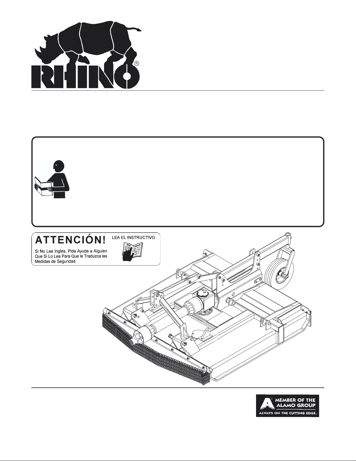
LUMBERJACK
60/72
TREE CUTTER
Revised 02-02 Effective Serial No. LJ 60-10001 Through Current P/N 00772058C
Effective Serial No. LJ 72- 10330Through Current
OPERATOR'S MANUAL
This Operator's Manual is an integral part of the safe operation
of this machine and must be maintained with the unit at all times.
READ, UNDERSTAND, and FOLLOW the Safety and Operation
Instructions contained in this manual before operating the
equipment. If the Operator's Manual is not with the equipment,
contact your local dealer or Servis-Rhino (800-446-5158) to
obtain a free copy before operating the equipment.(Some
shipping and handling charges may apply)
®
RHINO
1020 S. Sangamon Ave.
Gibson City, IL 60936
800-446-5158
Email: parts@servis-rhino.com
®
© 2004 Alamo Group Inc.
$0.00
Page 2
TO THE OWNER/OPERATOR/DEALER
All implements with moving parts are potentially hazardous. There is no substitute for a cautious, safe-minded
operator who recognizes the potential hazards and follows reasonable safety practices. The manufacturer has
designed this implement to be used with all its safety equipment properly attached to minimize the chance of
accidents.
BEFORE YOU START!! Read the safety messages on the implement and shown in your manual.
Observe the rules of safety and common sense!
WARRANTY INFORMATION:
Read and understand the complete Warranty Statement found in this Manual. Fill out the Warranty
Registration Form in full and return it within 30 Days. Make certain the Serial Number of the Machine is
recorded on the Warranty Card and on the Warranty Form that you retain. The use of "will-fit" parts will void
your warranty and can cause catastrophic failure with possible injury or death.
Page 3

BE SAFE!
BE ALERT!
BE ALIVE!
BE TRAINED
before operating
the Mower!
Safety T raining
Makes the Difference
In order to reduce accidents and enhance the safe operation of mowers, Alamo Group Ag Division, in
cooperation with other industry manufacturers has developed the AEM/FEMA Industrial and Agricultural
Mower Safety Practices video and guide book.
The video will familiarize and instruct mower-tractor operators in safe practices when using industrial and
agricultural mowing equipment. It is important that Every Mower Operator be educated in the operation of
their mowing equipment and be able to recognize the potential hazards that can occur while operating a
mower . This video, along with the mower operator’ s manual and the warning messages on the mower, will
significantly assist in this important education.
Y our Authorized Alamo Ag Dealer may have shown this video and presented you a DVD Video when you
purchased your mower . If you or any mower operator have not seen this video, Watch the Video, Read
this Operator’ s Manual, and Complete the Video Guidebook before operating your new mower . If you
do not understand any of the instructions included in the video or operator’s manual or if you have any
questions concerning safety of operation, contact your supervisor, dealer or Alamo Group Ag.
If you would like a VHS video tape of the video, please email AEMVideo@alamo-group.com or Fax AEM
VHS V ideo at (830) 372-9529 or mail in a completed copy of the form on the back of this page to AEM
VHS V ideo 1502 E W alnut Street, Seguin, TX 78155. and request the VHS video version. Please include
your name, mailing address, mower model and serial number .
Every operator should be trained for each piece of equipment (Tractor and Mower), understand the intended
use, and the potential hazards before operating the equipment.
Page 4

Alamo Group Ag. Division is willing to provide
one (1) AEM Mower Safety Practices Video
Please Send Me: VHS Format – AEM/FEMA Mower Operator Safety Video
DVD Format – AEM/FEMA Mower Operator Safety Video
Mower Operator’s Manual
AEM Mower Operator’s Safety Manual
Requester Name:
Requester Address:
City
State
Zip Code
Mower Model: Serial Number:
Date Purchased: Dealer Salesperson:
Dealership Name: Dealership Location:
Phone:
Mail to:
Or Fax to:
Or Email to:
AEM V ideo Services
1502 E Walnut street
Seguin, TX 78155
(830) 372-9529
AEMVideo@alamo-group.com
Page 5

TABLE OF CONTENTS
SAFETY SECTION ...................................................................................................................................... 1-1
Safety Information .................................................................................................................................. 1-2
Safety Decal Location............................................................................................................................1-11
Safety Decals.........................................................................................................................................1-12
Federal Laws And Regulations................................................................................................................1-14
INTRODUCTION SECTION ........................................................................................................................... .2-1
ASSEMBLY SECTION.......................................................................................................................................3-1
A-Frame Assembly.......................................................................................................................................3-2
Gearbox Shield.............................................................................................................................................3-3
Driveline Attachment.....................................................................................................................................3-3
Front Chainguard Assembly................................................................................................................... 3-5
OPERATION SECTION ............................................................................................................................... .4-1
MAINTENANCE SECTION................................................................................................................................5-1
Lubrication ............................................................................................................................................. 5-2
Gearbox ................................................................................................................................................. 5-3
Tail Wheel Assembly .............................................................................................................................. 5-3
Driveline ................................................................................................................................................. 5-4
Blade ...................................................................................................................................................... 5-5
Slip Clutch..................................................................................................................................................5-6
Storage .................................................................................................................................................. 5-8
Recommended Torque .............................................................................................................................5-8
Page 6

Page 7

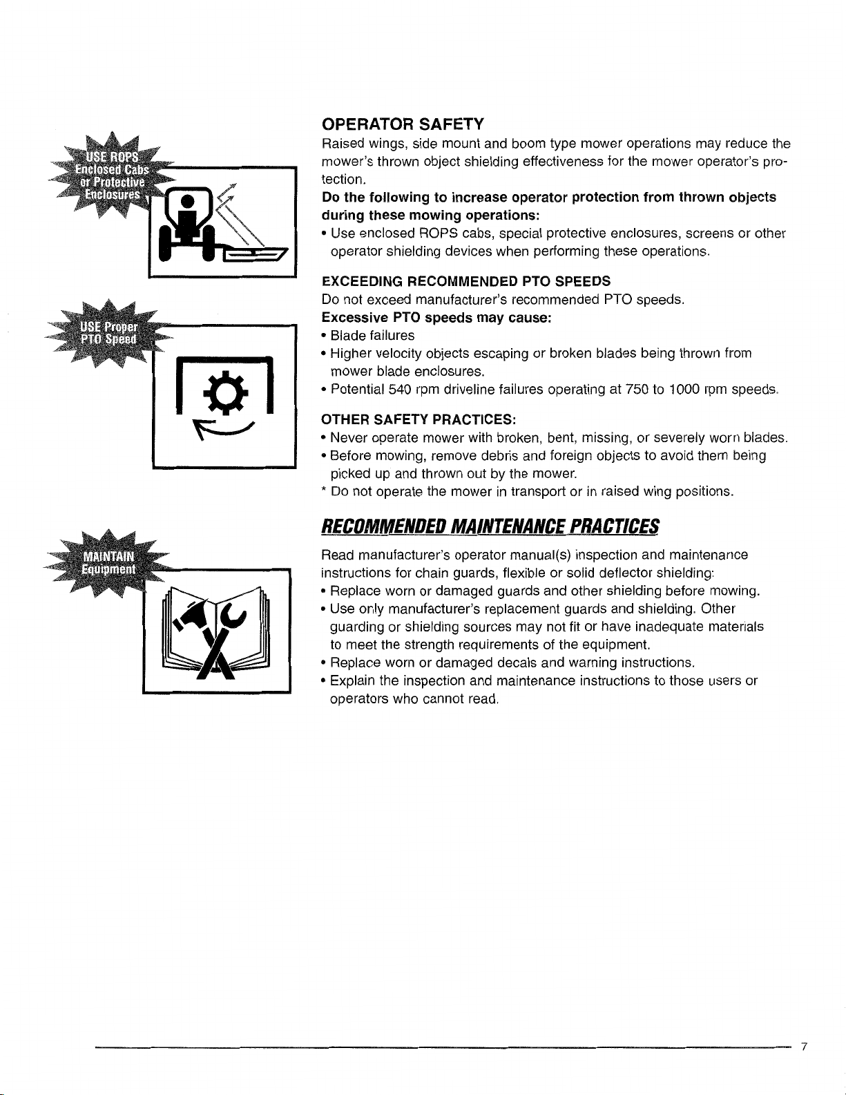
SAFETY
SECTION
Safety Section 1-1
Page 8
SAFETY
A safe and careful operator is the best operator. Safety is of primary importance to the manufacturer and should be to the owner/operator. Most accidents can be avoided by being aware of
your equipment, your surroundings, and observing certain precautions. The first section of this
manual includes a list of Safety Messages that, if followed, will help protect the operator and
bystanders from injury or death. Read and understand these Safety Messages before assembling, operating or servicing this implement. This equipment should only be operated by those
persons who have read the Manual, who are responsible and trained, and who know how to do
so safely and responsibly.
SAFETY
The Safety Alert Symbol combined with a Signal Word, as seen below, is used throughout this
manual and on decals which are attached to the equipment. The Safety Alert Symbol means:
“ATTENTION! BECOME ALERT! YOUR SAFETY IS INVOLVED!” The Symbol and Signal
Word are intended to warn the owner/operator of impending hazards and the degree of
possible injury faced when operating this equipment..
Practice all usual and customary safe working precautions and
above all---remember safety is up to YOU. Only YOU can prevent
serious injury or death from unsafe practices.
CAUTION! The lowest level of Safety Message; warns of possible injury. Decals
located on the Equipment with this Signal Word are Black and Yellow.
WARNING! Serious injury or possible death! Decals are Black and Orange.
DANGER! Imminent death/critical injury. Decals are Red and White. (SG-1)
READ, UNDERSTAND, and FOLLOW the following Safety
Messages. Serious injury or death may occur unless care is
taken to follow the warnings and instructions stated in the Safety
Messages. Always use good common sense to avoid hazards.
(SG-2)
© 2004 Alamo Group Inc.
Safety Section 1-2LJ60/72 02-02
Page 9
SAFETY
PELIGRO!
DANGER!
WARNING!
WARNING!
Si no lee Ingles, pida ayuda a alguien que
si lo lea para que le traduzca las medidas
de seguridad. (SG-3)
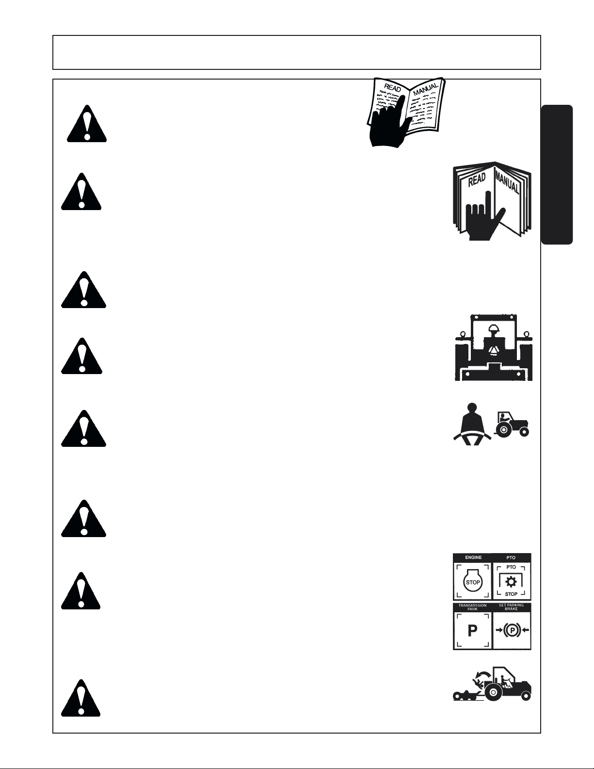
Never operate the Tractor or Implement until you have read and
completely understand this Manual, the Tractor Operator’s Manual,
and each of the Safety Messages found in the Manual or on the
Tractor and Implement. Learn how to stop the tractor engine
suddenly in an emergency. Never allow inexperienced or untrained
personnel too operate the Tractor and Implement without supervi-
Make sure the operator has fully read and understood the
sion.
manuals prior to operation. (SG-4)
Always maintain the safety decals in good readable condition. If the decals are missing, damaged,
or unreadable, obtain and install replacement decals immediately. (SG-5)
Make certain that the “Slow Moving Vehicle” (SMV) sign is installed in
such a way as to be clearly visible and legible. When transporting the
Equipment use the Tractor flashing warning lights and follow all local
traffic regulations. (SG-6)
INSTRUCTIVO!
¡LEA EL
SAFETY
WARNING!
WARNING!
DANGER!
DANGER!
Operate this Equipment only with a Tractor equipped with an
approved roll-over-protective system (ROPS). Always wear seat
belts. Serious injury or even death could result from falling off the
tractor--particularly during a turnover when the operator could be
pinned under the ROPS. (SG-7)
Do not modify or alter this Implement. Do not permit anyone to modify or alter this Implement,
any of its components or any Implement function. (SG-8)
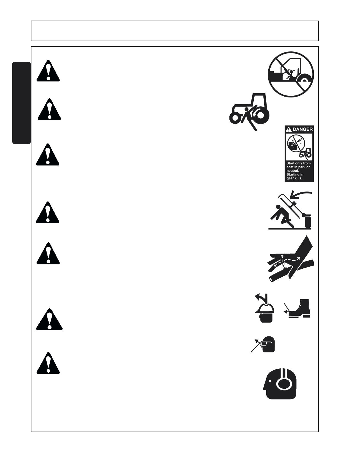
BEFORE leaving the tractor seat, always engage the brake and/or set
the tractor transmission in parking gear, disengage the PTO, stop the
engine, remove the key, and wait for all moving parts to stop. Place
the tractor shift lever into a low range or parking gear to prevent the
tractor from rolling. Never dismount a Tractor that is moving or while
the engine is running. Operate the Tractor controls from the tractor
seat only. (SG-9)
Never allow children or other persons to ride on the Tractor or Implement.
Falling off can result in serious injury or death. (SG-10)
© 2004 Alamo Group Inc.
Safety Section 1-3LJ60/72 02-02
Page 10
SAFETY
DANGER!
WARNING!
SAFETY
DANGER!
DANGER!
Never allow children to operate or ride on the Tractor or Implement.
Do not mount the Tractor while the tractor is moving.
Mount the Tractor only when the Tractor and all moving
parts are completely stopped. (SG-12)
Start tractor only when properly seated in the Tractor seat. Starting a tractor in
gear can result in injury or death. Read the Tractor operators manual for proper
starting instructions.
Never work under the Implement, the framework, or any lifted component
unless the Implement is securely supported or blocked up to prevent
sudden or inadvertent falling which could cause serious injury or even
death. (SG-14)
(SG-13)
(SGM-11)
DANGER!
WARNING!
CAUTION! PROLONGED EXPOSURE TO LOUD NOISE MAY CAUSE PER-
Do not operate this Equipment with hydraulic oil leaking. Oil is
expensive and its presence could present a hazard. Do not check for
leaks with your hand! Use a piece of heavy paper or cardboard. Highpressure oil streams from breaks in the line could penetrate the skin
and cause tissue damage including gangrene. If oil does penetrate the
skin, have the injury treated immediately by a physician knowledgeable and skilled in this procedure. (SG-15)
The operator and all support personnel should wear hard hats,
safety shoes, safety glasses, and proper hearing protection at all
times for protection from injury including injury from items thrown
by the equipment. (SG-16)
MANENT HEARING LOSS! Tractors with or without an Implement
attached can often be noisy enough to cause permanent hearing
loss. We recommend that you always wear hearing protection if
the noise in the Operator’s position exceeds 80db. Noise over
85db over an extended period of time will cause severe hearing
loss. Noise over 90db adjacent to the Operator over an extended
period of time will cause permanent or total hearing loss. Note:
Hearing loss from loud noise [from tractors, chain saws, radios,
and other such sources close to the ear] is cumulative over a
lifetime without hope of natural recovery. (SG-I7)
Safety Section 1-4LJ60/72 02-02
© 2004 Alamo Group Inc.
Page 11
SAFETY
WARNING! Transport only at safe speeds. Serious accidents and injuries can re-
sult from operating this equipment at unsafe speeds. Understand the
Tractor and Implement and how it handles before transporting on streets
and highways. Make sure the Tractor steering and brakes are in good
condition and operate properly.
Before transporting the Tractor and Implement, determine the safe
transport speeds for you and the equipment. Make sure you abide by
the following rules:
Test the tractor at a slow speed and increase the speed slowly.
1.
Apply the Brakes smoothly to determine the stopping
characteristics of the Tractor and Implement.
As you increase the speed of the Tractor the stopping distance
increases. Determine the maximum safe transport speed for
you and this Equipment.
Test the equipment at a slow speed in turns. Increase the speed
2.
through the turn only after you determine that it is safe to operate
at a higher speed. Use extreme care and reduce your speed when
turning sharply to prevent the tractor and implement from turning
over. Determine the maximum safe turning speed for you and this
equipment before operating on roads or uneven ground.
Only transport the Tractor and Implement at the speeds that you
3.
have determined are safe and which allow you to properly control the
equipment.
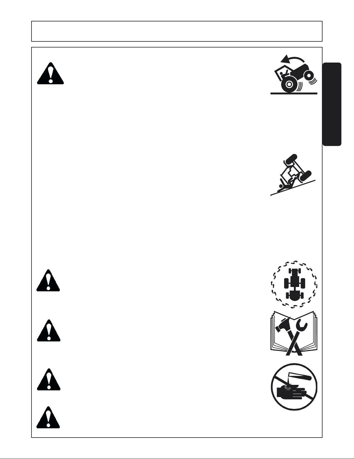
Be aware of the operating conditions. Do not operate the Tractor with weak or faulty brakes. When operating
down a hill or on wet or rain slick roads, the braking distance increases: use extreme care and reduce your
speed. When operating in traffic always use the Tractor’s flashing warning lights and reduce your speed. Be
aware of traffic around you andwatch out for the other guy. (SG-19)
SAFETY
WARNING!
WARNING!
WARNING!
DANGER!
Never attempt to lubricate, adjust, or remove material from the
Implement while it is in motion or while tractor engine is running.
Make sure the tractor engine is off before working on the Implement.
(SG-20)
Periodically inspect all moving parts for wear and replace when
necessary with authorized service parts. Look for loose fasteners,
worn or broken parts, and leaky or loose fittings. Make sure all pins
have cotter pins and washers. Serious injury may occur from not
maintaining this machine in good working order. (SG-21)
Always read carefully and comply fully with the manufacturers instructions when handling oil, solvents, cleansers, and any other chemical
agent. (SG-22)
Never run the tractor engine in a closed building or without adequate ventilation. The exhaust fumes can be hazardous to your
health.
(SG-23)
Safety Section 1-5LJ60/72 02-02
© 2004 Alamo Group Inc.
Page 12
SAFETY
DANGER!
DANGER!
SAFETY
WARNING!
DANGER!
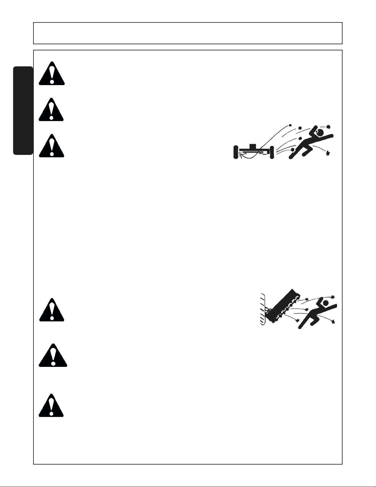
KEEP AWAY FROM ROTATING ELEMENTS to prevent entanglement
and possible serious injury or death.
(SG-24)
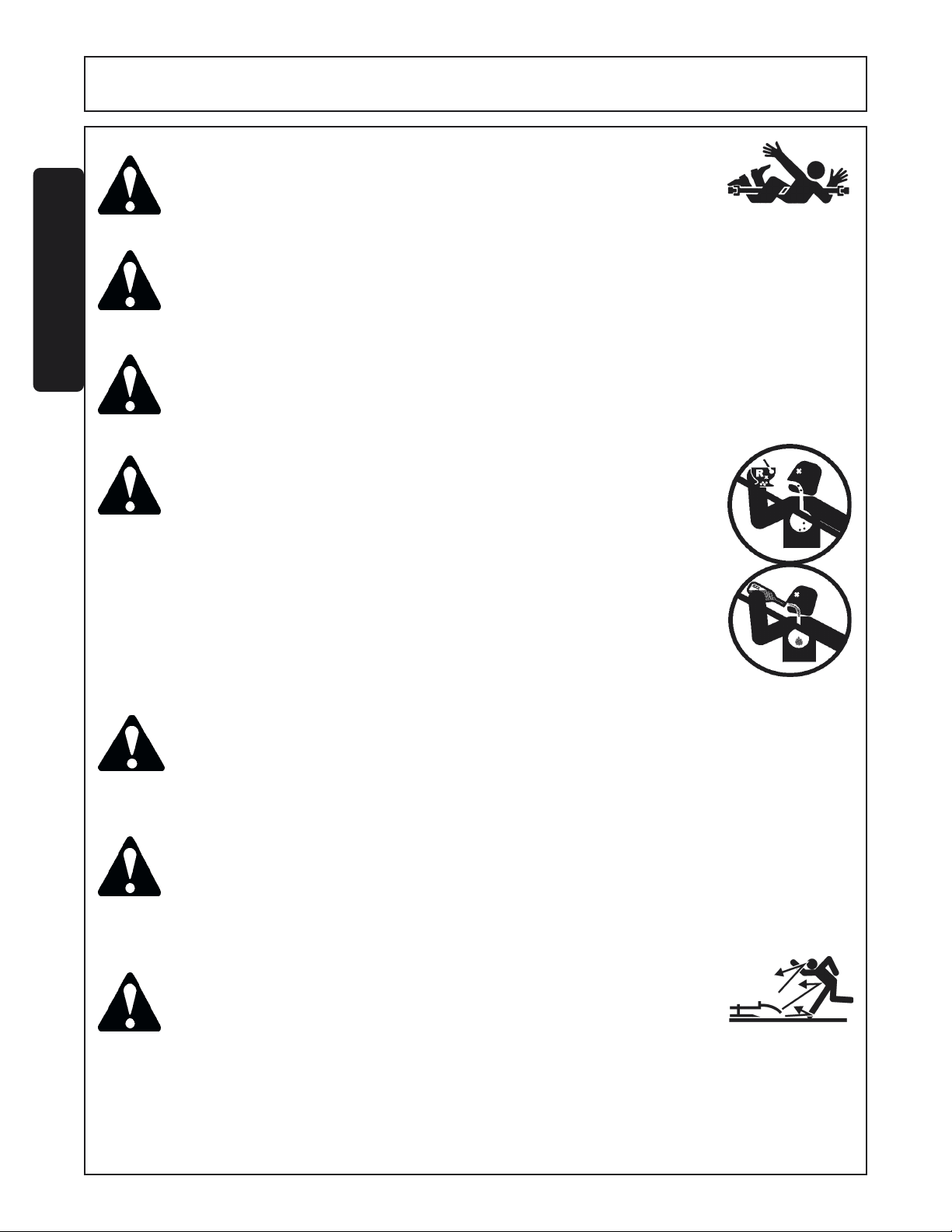
Never allow children to play on or around Tractor or Implement. Children can slip or fall off the
Equipment and be injured or killed. Children can cause the Implement to shift or fall crushing
themselves or others. (SG-25)
Do not exceed the rated PTO speed for the Implement. Excessive PTO speeds can cause
Implement driveline or blade failures resulting in serious injury or death.
(SG-26)
NEVER use drugs or alcohol immediately before or while operating the
Tractor and Implement. Drugs and alcohol will affect an operator’s
alertness and coordination and therefore affect the operator’s ability to
operate the equipment safely. Before operating the Tractor or
Implement, an operator on prescription or over-the-counter medication must consult a medical professional regarding any side effects of
the medication that would hinder their ability to operate the Equipment
safely. NEVER knowingly allow anyone to operate this equipment
when their alertness or coordination is impaired.
Serious injury or
death to the operator or others could result if the operator is under the
influence of drugs or alcohol. (SG-27)
DANGER! Operate the Tractor and/or Implement controls only while properly seated in the Tractor seat with
the seat belt securely fastened around you. Inadvertent movement of the Tractor or Implement
may cause serious injury or death. (SG-29)
WARNING!
Mow only in conditions where you have clear visibility in daylight or with adequate artificial lighting.
Never mow in darkness or foggy conditions where you cannot clearly see at least 100 yards in front
and to the sides of the tractor and mower. Make sure that you can clearly see and identify
passersby, steep slopes, ditches, drop-offs, overhead obstructions, power lines, debris and
foreign objects. If you are unable to clearly see this type of items discontinue mowing. (SGM-
1)
DANGER!
There are obvious and hidden potential hazards in the operation of
this Mower. REMEMBER! This machine is often operated in heavy
brush and in heavy weeds. The Blades of this Mower can throw
objects if shields are not properly installed and maintained. Serious
injury or even death may occur unless care is taken to insure the
safety of the operator, bystanders, or passersby in the area. Do not
operate this machine with anyone in the immediate area. Stop
mowing if anyone is within 100 yards of mower. (SGM-2)
© 2004 Alamo Group Inc.
Safety Section 1-6LJ60/72 02-02
Page 13
SAFETY
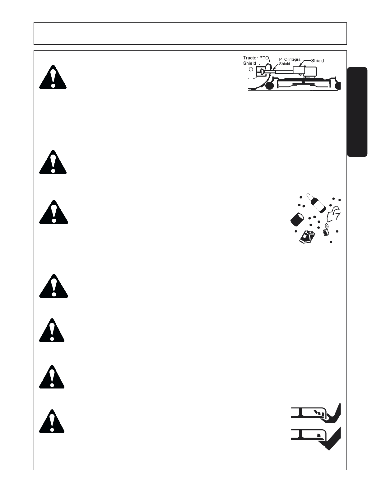
DANGER! All Safety Shields, Guards and Safety devices including
(but not limited to) - the Deflectors, Chain Guards, Steel
Guards, Gearbox Shields, Hydraulic Tank Shields, and
Retractable Door Shields should be used and maintained in good working condition. All safety devices
should be inspected carefully at least daily for missing
or broken components. Missing, broken, or worn items
must be replaced at once to reduce the possibility of
injury or death from thrown objects, entanglement, or
blade contact. (SGM-3)
SAFETY
DANGER!
WARNING!
WARNING!
WARNING!
The rotating parts of this machine have been designed and tested for rugged use. However,
they could fail upon impact with heavy, solid objects such as steel guard rails and concrete
abutments. Such impact could cause the broken objects to be thrown outward at very high
velocities. To reduce the possibility of property damage, serious injury, or even death, never
allow the cutting blades to contact such obstacles. (SGM-4)
Extreme care should be taken when operating near loose objects
such as gravel, rocks, wire, and other debris. Inspect the area before
mowing. Foreign objects should be removed from the site to prevent
machine damage and/or bodily injury or even death. Any objects that
cannot be removed must be clearly marked and carefully avoided by
the operator. Stop mowing immediately if blades strike a foreign
object. Repair all damage and make certain rotor or blade carrier is
balanced before resuming mowing. (SGM-5)
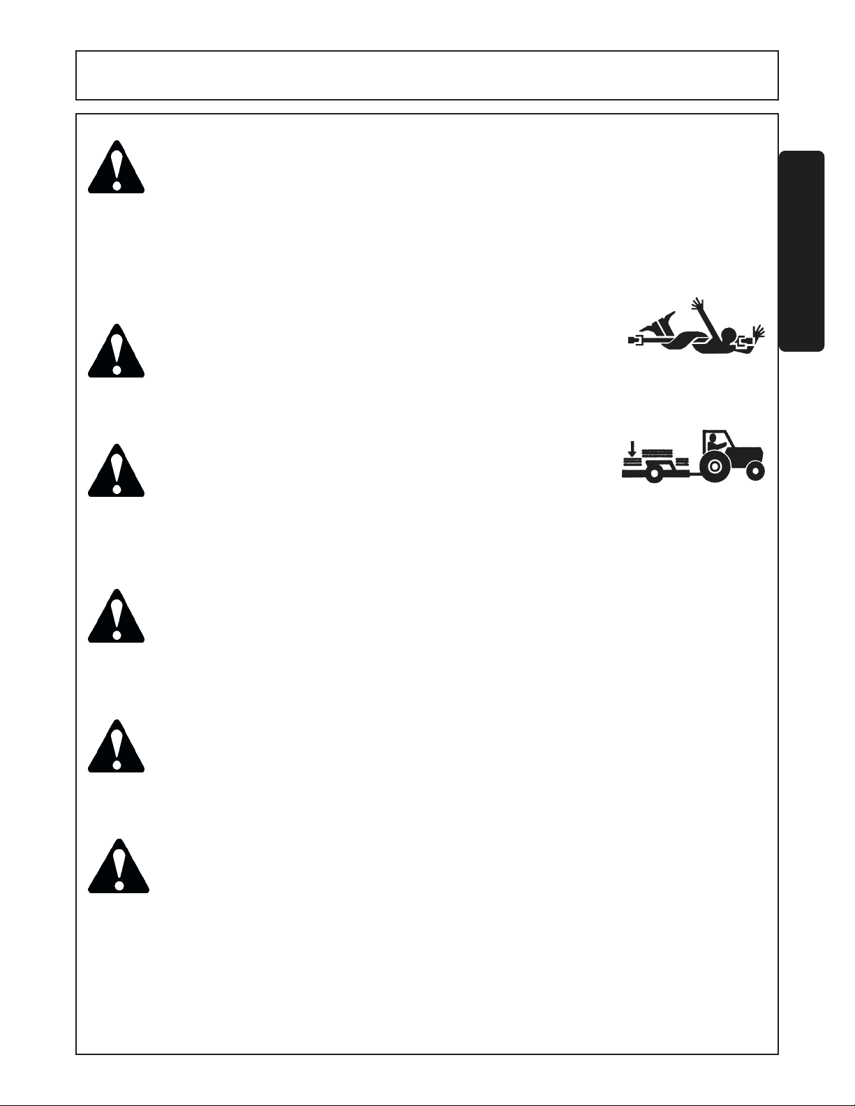
Many varied objects, such as wire, cable, rope, or chains, can become entangled in the operating
parts of the mower head. These items could then swing outside the housing at greater velocities
than the blades. Such a situation is extremely hazardous and could result in serious injury or even
death. Inspect the cutting area for such objects before mowing. Remove any like object from the
site. Never allow the cutting blades to contact such items. (SGM-6)
Mow at the speed that you can safely operate and control the tractor and mower. Safe mowing
speed depends on terrain condition and grass type, density, and height of cut. Normal ground
speed range is from 0 to 5 mph. Use slow mowing speeds when operating on or near steep slopes,
ditches, drop-offs, overhead obstructions, power lines, or when debris and foreign objects are to
be avoided. (SGM-7)
WARNING!
WARNING!
© 2004 Alamo Group Inc.
Avoid mowing in reverse direction when possible. Check to make sure there are no persons are
behind the mower and use extreme care when mowing in reverse. Mow only at a slow ground
speed where you can safely operate and control the tractor and mower. Never mow an area in
the reverse direction that you have not inspected and removed debris or foreign material. (SGM-
8)
Do not put hands or feet under mower decks. Blade Contact can result
serious injury or even death. (SGM-9)
Safety Section 1-7LJ60/72 02-02
Page 14
SAFETY
DANGER! Replace bent or broken blade with new blades. NEVER ATTEMPT TO STRAIGHTEN
BLADES SINCE THIS WILL LIKELY CRACK OR OTHERWISE DAMAGE THE BLADE
WITH SUBSEQUENT FAILURE AND POSSIBLE SERIOUS INJURY FROM THROWN
BLADES. (SGM-10)
WARNING!
SAFETY
DANGER!
Do not mow with two machines in the same area except with Cab tractors with the windows closed.
(SGM-11)
Rotary Mowers are capable under adverse conditions
of throwing objects for great distances (100 yards
or more) and causing serious injury or death. Follow
safety messages carefully
STOP MOWING IF PASSERSBY ARE WITHIN 100 YARDS UNLESS:
-Front and Rear Deflectors, Chain Guards, or Bands are installed
and in good, workable condition;
-Mower sections or Wings are running close to and parallel to the
ground without exposed Blades;
-Passersby are outside the existing thrown-object zone;
-All areas have been thoroughly inspected and all foreign material
such as rocks, cans, glass, and general debris has been removed.
NOTE: Where there are grass and weeds high enough to hide debris that could be struck by
the blades, the area should be: inspected and large debris removed, mowed at an intermediate
height, inspected, closely with any remaining debris being removed, and mowed again at
desired final height. (This will also reduce power requiredto mow, reduce wear and tear on
the Mower drivetrain, spread cut material better, eliminate streaking, and make the final cut
more uniform.)
(SRM-1)
WARNING!
WARNING!
WARNING!
© 2004 Alamo Group Inc.
Do not let the Blades turn when the Mower Deck is raised for
any reason, including clearance or for turning. Raising the
Mower deck exposes the Cutting Blades which creates a
potentially serious hazard and could cause serious injury or
even death from objects thrown from the Blades. (SRM-7)
Never leave Tractor and Implemented unattended while the implement is in the lifted position.
Accidental operation of lifting lever or a hydraulic failure may cause sudden drop of unit with
injury or death by crushing. To properly park the implement when disconnecting it from the tractor,
lower the stand and put the retaining pin securely in place, or put a secure support under the AFrame. Lower the implement carefully to the ground. Do not put hands or feet under lifted
components. (S3PT-1)
Be particularly careful when transporting the Implement with the Tractor. Turn curves or go up
hills only at a low speed and using a gradual steering angle. Rear mounted implements move
the center of gravity to the rear and remove weight from the front wheels. Make certain, by
adding front ballast, that at least 20% of the tractor’s weight is on the front wheels to prevent
rearing up, loss of steering control or Tractor tip-over. Slow down on rough or uneven surfaces
to prevent loss of steering control which could result in property damage or possible injury. Do
not transport unless 3-Point lift lever is fully raised and in the latched transport position. Dropping
implement in transport can cause serious damage to the tractor and/or Implement and possibly
cause the operator or others to be injured or killed. (S3PT-2)
Safety Section 1-8LJ60/72 02-02
Page 15
SAFETY
DANGER!
DANGER!
WARNING!
There are obvious and hidden potential hazards in the operation of this Implement as in all
power-driven or pulled equipment. REMEMBER! This machine is often operated in rough
terrain conditions that include tall grass, weeds, gullies, holes, slopes, hidden obstructions and
the like. Serious injury or even death may occur unless care is taken to assure the safety of the
operator and bystanders in the area. Do not operate this machine with anyone in the immediate
area. (S3PT-7)
Make sure the PTO shield is installed when using PTO-driven equipment.
Always replace the PTO shield if it is damaged or missing. (S3PT-8)
Relieve hydraulic pressure prior to doing any maintenance or repair work
on the Implement. Place the Implement on the ground or securely
blocked up, disengage the PTO, and turn off the tractor engine. Push
and pull the Remote Cylinder lever in and out several times prior to
starting any maintenance or repair work. (S3PT-9)
SAFETY
WARNING!
DANGER!
DANGER!
The rotating parts of this machine continue to rotate even after the PTO has been turned off. The
operator should remain in his seat for 60 seconds after the brake has been set, the PTO
disengaged, the tractor turned off, and all evidence of rotation has ceased. (S3PT-10)
“Wait a minute...Save a life!”
Always disconnect the main PTO Driveline from the Tractor before performing service on the
Implement. Never work on the Implement with the tractor PTO driveline connected and running.
Rotating Parts, Blades or Drivelines could turn without warning and cause immediate
entanglement, injury or death. (S3PT-11)
This Implement is wider than the Tractor. Be careful when operating or transporting this
equipment to prevent the Implement from running into or striking sign posts, guard rails,
concrete abutments or other solid objects. Such an impact could cause the Implement and
Tractor to pivot violently resulting in loss of steering control, serious injury, or even death.
Never allow the Implement to contact obstacles. (S3PT-12)
© 2004 Alamo Group Inc.
Safety Section 1-9LJ60/72 02-02
Page 16
SAFETY
WARNING!
SAFETY
WARNING!
DANGER!
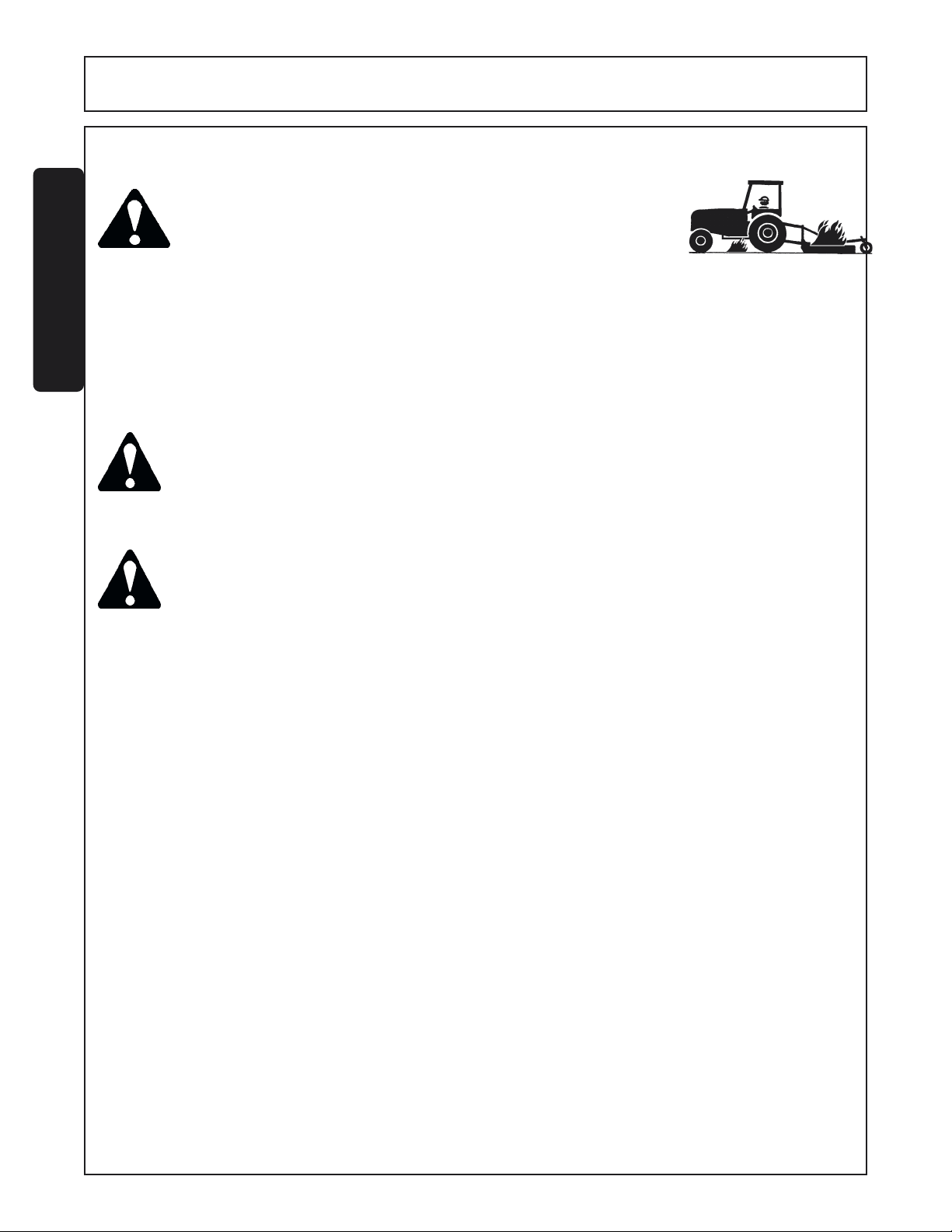
Follow these guidelines to reduce the risk of equipment and grass fires
while operating, servicing, and repairing the Mower and Tractor:
-Equip the Tractor with a fire extinguisher in an accesible location.
-Do Not operate the Mower on a Tractor with an underframe exhaust.
-Do Not smoke or have an open flame near the Mower and Tractor.
-Do Not drive into burning debris or freshly burnt areas.
-Ensure slip clutches are properly adjusted to prevent excessive slippage
and plate heating.
-Never allow clippings or debris to collect near drivelines, slip clutches,
and gearboxes. Periodically shut down the Tractor and Mower and clean
clippings and collected debris from the mower deck.
Do not mow with two machines in the same area except with Cab tractors with the windows closed.
(SGM-11)
Replace bent or broken blade with new blades. NEVER ATTEMPT TO STRAIGHTEN OR WELD
ON BLADES SINCE THIS WILL LIKELY CRACK OR OTHERWISE DAMAGE THE BLADE
WITH SUBSEQUENT FAILURE AND POSSIBLE SERIOUS INJURY FROM THROWN BLADES.
(SGM-10)
(SGM-12)
In addition to the design and configuration of this Implement, including Safety Signs and Safety Equipment,
hazard control and accident prevention are dependent upon the awareness, concern, prudence, and proper
training of personnel involved in the operation, transport, maintenance, and storage of the machine. Refer also
to Safety Messages and operation instruction in each of the appropriate sections of the Tractor and Equipment
Manuals. Pay close attention to the Safety Signs affixed to the Tractor and Equipment. (SG-18)
PARTS INFORMATION
Servis-Rhino mowers use balanced and matched system components for blade carriers, blades, cuttershafts,
knives, knife hangers, rollers, drivetrain components, and bearings. These parts are made and tested to
Servis-Rhino specifications. Non-genuine "will fit" parts do not consistently meet these specifications. The
use of “will fit” parts may reduce mower performance, void mower warranties, and present a safety hazard.
Use genuine Servis-Rhino mower parts for economy and safety. (SPRM-1)
SEE YOUR SERVIS-RHINO DEALER
Safety Section 1-10LJ60/72 02-02
© 2004 Alamo Group Inc.
Page 17
SAFETY
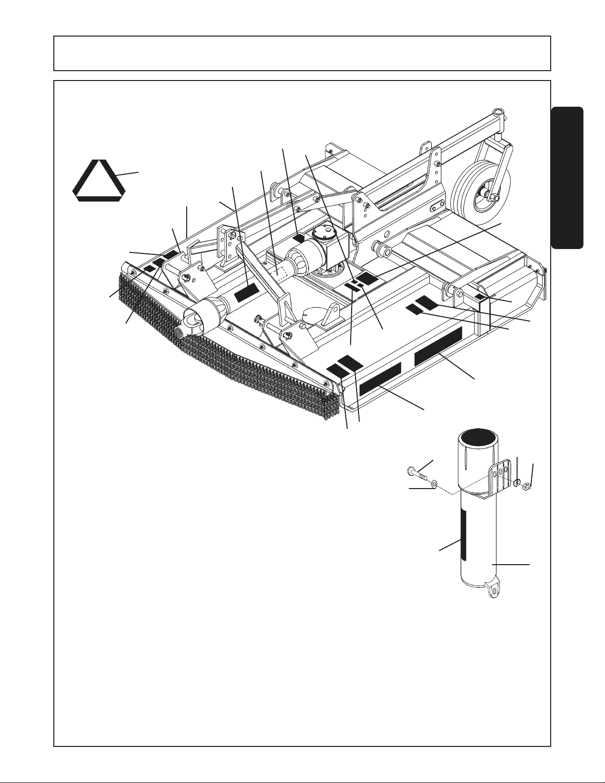
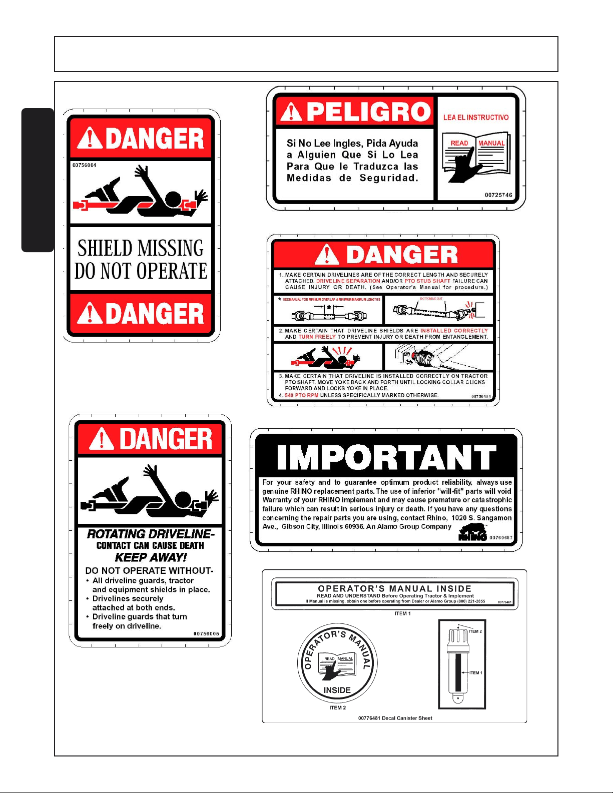
NOTE: Rhino supplies safety decals on this product to promote safe operation. Damage to
the decals may occur while in shipping, use, or reconditioning. Rhino cares about the safety
of its customers, operators, and bystanders, and will replace the safety decals on this product
in the field, free of charge (Some shipping and handling charges may apply). Contact your
Rhino dealer to order replacement decals.
11
4
14
15
12
10
2
SAFETY
16
7
13
9
7A
12
8
ITEM PART NO. QTY LEVEL DESCRIPTION
1 00749117 1 DANGER Multi-Hazard
2 00756004 (*1) DANGER D/L Shield missing
3 00725746 1 PELIGRO Translate Safety Material
4 00756005 (*1) DANGER Rotating Driveline
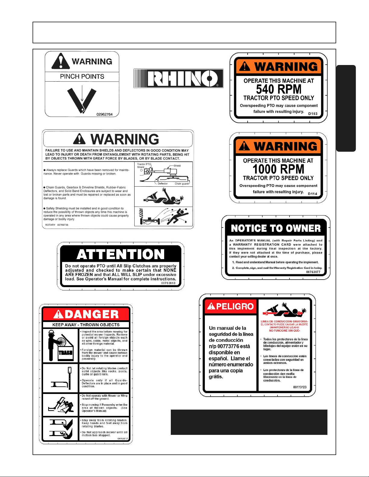
5 02962764 2 DANGER Pinch Point
6 00756494 (1) DANGER Driveline Hazards
7 00760657 1 IMPORTANT Genuine Rhino Parts
7A 00773723 1 PELIGRO Rotating Driveline Translation
8 00769736 1 WARNING Use/Repair Shields & Guards
9 00769737 2 DANGER Blades/Thrown Objects
10 D103 [(1)] WARNING 540 RPM Operation
D114 [(1)] WARNING 1000 RPM Operation
11 03200347 *1 REFLECT SMV Emblem
12 00763613 (1) INSTRUCT Slip Clutch Adjustment
13 00763977 1 INSTRUCT Notice To Owner
14 D303 2 DECAL Rhino
15 00771818 2 DECAL Lumberjack
16 NFS 1 SRLPLT Serial Plate
17 00756059 1 DECAL Oil Leak
18 00776481 1 INSTRUCT Operators Manual Inside (Decal)
19 00776031 1 --------------- Canister, Operators Manual
20 00772058C 1 --------------- Operators Manual
21 10058000 3 --------------- Bolt
22 00024100 6 --------------- Flatwasher
23 02959924 3 --------------- Locknut
3
22
14
18
21
15
6
5
1
9
22
23
19
* Furnished by Supplying Manufacturer
[( )] Select one or the other on Mech Models only
( ) Mechanical Models Only
[ ] Select one or the other
© 2004 Alamo Group Inc.
Safety Section 1-11LJ60/72 02-02
Page 18
SAFETY
SAFETY
3 - 00725746
2 - 00756004
6 - 00756494
4 - 00756005
1 - - 00749117 - Not Shown
(See Inside Front Cover of Manual)
11 - - 03200347 SMV Reflector
© 2004 Alamo Group Inc.
7 - 00760657
18 - 00776481
Safety Section 1-12LJ60/72 02-02
Page 19
SAFETY
5 - 02962764
14 - D303
SAFETY
10 - D103
10 - D114
8 - 00769736
© 2004 Alamo Group Inc.
13 - 00763977
12 - 00763613
9 - 00769737
7A - 00773723
LUMBERJACK
15 - 00771818
Safety Section 1-13LJ60/72 02-02
Page 20

SAFETY
FEDERAL LAWS AND REGULATIONS
This section is intended to explain in broad terms the concept and effect of federal laws and regulations concerning
employer and employee equipment operators. This section is not intended as a legal interpretation of the law and
should not be considered as such.
Employer-Employee Operator Regulations
U.S. Public Law 91-596 (The Williams-Steiger Occupational and Health Act of 1970) OSHA
This Act Seeks:
SAFETY
“...to assure so far as possible every working man and woman in the nation safe and healthful
working conditions and to preserve our human resources...”
DUTIES
Sec. 5 (a) Each employer(1) shall furnish to each of his employees employment and a place of employment which are free
from recognized hazards that are causing or are likely to cause death or serious physical harm to
his employees;
(2) shall comply with occupational safety and health standards promulgated under this Act.
(b) Each employee shall comply with occupational safety and health standards and all rules,
regulations and orders issued pursuant to this Act which are applicable to his own actions
and conduct.
OSHA Regulations
OSHA regulations state in part: “At the time of initial assignment and at least annually thereafter,
the employer shall instruct every employee in the safe operation and servicing of all equipment with
which the employee is, or will be involved.”
Employer Responsibilities:
To ensure employee safety during Tractor and Implement operation, it is the employer’s responsibility to:
1. Train the employee in the proper and safe operation of the Tractor and Implement.
2. Require that the employee read and fully understand the Tractor and Implement Operator’s manual.
3. Permit only qualified and properly trained employees to operate the Tractor and Implement.
4. Maintain the Tractor and Implement in a safe operational condition and maintain all shields and guards on the
equipment.
5. Ensure the Tractor is equipped with a functional ROPS and seat belt and require that the employee operator
securely fasten the safety belt and operate with the ROPS in the raised position at all times.
6. Forbid the employee operator to carry additional riders on the Tractor or Implement.
7. Provide the required tools to maintain the Tractor and Implement in a good safe working condition and provide
the necessary support devices to secure the equipment safely while performing repairs and service.
8. Require that the employee operator stop mowing if bystanders or passerbys come within 100 yards.
Child Labor Under 16 Years of Age
Some regulations specify that no one under the age of 16 may operate power machinery. It is your responsibility
to know what these regulations are in your own area or situation. (Refer to U.S. Dept. of Labor, Employment
Standard Administration, Wage & Home Division, Child Labor Bulletin #102.)
Safety Section 1-14LJ60/72 02-02
© 2004 Alamo Group Inc.
Page 21
Page 22
Page 23
Page 24
Page 25
Page 26
Page 27
Page 28
Page 29
Page 30
Page 31

Page 32

Page 33

Page 34

Page 35

Page 36

Page 37

Page 38

Page 39

Page 40

Page 41

Page 42

Page 43

Page 44

Page 45

Page 46

Page 47

Page 48

Page 49

Page 50

Page 51

Page 52

Page 53

Page 54

Page 55

Page 56

Page 57

Page 58

Page 59

Page 60

Page 61

Page 62

Page 63

Page 64

Page 65

INTRODUCTION
SECTION
Introduction Section 2-1
Page 66

INTRODUCTION
This Cutter is designed with care and built with quality materials by skilled workers. Proper assembly,
maintenance, and operating practices, as described in this manual, will help the owner/operator get years of
satisfactory service from the machine.
The purpose of this manual is to familiarize, instruct, and train. The Assembly Section instructs the owner/operator
in the correct assembly of the Mower using standard and optional equipment. The Parts Listing section is designed
to familiarize the owner/operator with replaceable parts on the Mower. This section provides exploded assembly
drawings of each mower component illustrating each piece and the corresponding part number.
Careful use and timely service saves extensive repairs and costly downtime losses. The Operation and
Maintenance Sections of the manual train the owner/operator how to work the Mower correctly and attend to
appropriate maintenance. The Trouble Shooting Guide helps diagnose difficulties with mower and offers solution
to the problems.
Safety is of primary importance to the owner/operator and to the manufacturer. The first section of this manual
includes a list of Safety Messages, that, if followed, will help protect the operator and bystanders from injury or
death. Many of the Safety Messages will be repeated throughout the manual. The owner/operator/dealer should
know these Safety Messages before assembly and be aware of the hazards of operating this mower during
assembly, use, and maintenance. The Safety Alert Symbol combined with a Signal Word, as seen below, is
INTRODUCTION
intended to warn the owner/operator of impending hazards and the degree of possible injury faced when operating
this machine.
CAUTION
The lowest level of Safety Message; warns of possible minor injury. Decals
located on the Mower with this Signal Word are Black and Yellow.
WARNING
DANGER
BEFORE OPERATING THIS MACHINE:
1. Carefully read the Operator’s Manual, completely understand the Safety Messages and instructions, and know
how to operate correctly both the tractor and Mower.
2. Fill out the Warranty Card in full. Be sure to answer all questions, including the Serial Number of the Mower.
Mail promptly using the return envelope included with the Operator’s Manual.
Serious injury or possible death! Decals are Black and Orange.
Imminent death/critical injury. Decals are Red and White.
ATTENTION OWNER/OPERATOR
NOTE: Warranties are honored only if completed “Owner Registration and Warranty” forms are received by Alamo
Group within thirty days of delivery of the mower.
3. Record the Mower Model and Serial Numbers on the Warranty page at the end of the Operator’s Manual. Keep
this as part of the permanent maintenance file for the Mower.
LJ60/72 02-02
© 2004 Alamo Group Inc.
Introduction Section 2-2
Page 67

INTRODUCTION
INTRODUCTION
This cutter is available in lift-type models only. These rugged Cutters are designed for heavy-duty work. They can
cut brush up to 6" in diameter.
DANGER
A 60" unit requires a minimum of 60 hp
A 72" unit requires a minimum 90 HP Tractor with adequate front end weight is required.
WARNING
Front and rear, and left and right are determined by the normal direction of travel (the same as on your automobile).
LJ60/72 02-02
© 2004 Alamo Group Inc.
For Non-Agricultural use, OSHA, ASAE, SAE, and ANSI standards require the use of Chain
Guards, Deflectors, or Solid Skirts at all times. The Mower manufacturer strongly recommends
the use of Chain Gaurds, Deflectors, or Solid Skirts for Agricultural purposes as well to reduce the
risk of property damage, serious bodily injury, or even death from objects thrown out by or from
contact with the Cutting Blades.
At least 20% of the tractor’s total weight must be on the front tires with the Mower lifted to provide
adequate traction for safe steering under good conditions. Slow down on hills, rough terrain, and
curves.
Introduction Section 2-3
Page 68

Page 69

ASSEMBLY
SECTION
Assembly Section 3-1
Page 70

ASSEMBLY
This Cutter will attach to most tractors with Cat. II & III and II & III Quick Hitch. The Lumberjack can be purchased
for tractors with 540 or 1000 RPM PTO.
DEALER SET-UP INSTRUCTIONS
Assembly of this mower is the responsibility of the Servis-Rhino dealer. The mower should be delivered to the
owner completely assembled, lubricated, and adjusted for normal cutting conditions.
Set up mower as received from the factory with these instructions. Open parts box and lay parts out to make
location easy. Refer to the parts lists and exploded view drawings for more detail.
This mower is shipped partially assembled. Assembly will be easier if components are aligned and loosely
assembled before tightening hardware.
CAUTION! Always use personal protection devices such as eye, ear and feet protectors during
A-FRAME ASSEMBLY (FIGURE 1) 72" MODEL
To assemble the Mower’s A-Frame, follow the procedures listed below:
1. One side at a time, position the mower’s left and right A-Frame halves (28 and 26) between the respective front
set of mower deck lugs. Align A-frame hole with lug back hole and insert a 1” x 8” bolt (41). Install a 1” locknut (40)
onto bolt (41), but do not tighten at this point. Repeat procedure on other A-frame half.
2. To connect the two A-frame halves (28 and 26), place bushing (27) between frame halves’ lower front holes and
retain halves (28 and 26) and bushing (27) with a 1” x 4-1/2” bolt (42) and 1” locknut (43).
3. Insert spacer (23) between two front upper braces’ (19) farthest holes. NOTE: Front upper braces have 3 bolt
holes and lower rear braces 2 bolt holes. Insert bushing (24) into braces (19) and spacer (23). Align braces (19),
bushing (24), and spacers (23) between A-frame back holes and retain using a 3/4” x 4-1/2” bolt (34) and 3/4”
locknut (35).
4. Attach upper front braces (19) to lower rear braces (22) by first inserting bushings (20) into each upper front
brace (19) center hole. Then place lower rear braces (22) between upper front braces (19) and bushings and align
holes. Note: There will be separation between the upper front braces and no separation between the lower rear
braces when installed correctly. Retain sets of braces and bushings using 3/4” x 3” bolt (38) and 3/4” locknut (35).
5. Install bushing (21) between upper braces’ remaining open holes and insert 3/4” x 3” bolt (37) and 3/4” locknut
(35).
6. Place spacer (25) into set of lower rear braces. Insert spacer (23) on each side of lower rear brace holes and
place between mower deck rear lugs. Align brace holes and spacers with lug holes and insert a 3/4” x 4-1/2” bolt
(34) and locknut 3/4” (35).
assembly.
7. Tighten all bolts and locknuts per torque.
© 2004 Alamo Group Inc.
(FIGURE 1)
Assembly Section 3-2LJ60/72 02-02
Page 71

ASSEMBLY
A-FRAME ASSEMBLY (FIGURE 2) 60" MODEL
To assemble the Mower’s A-Frame, follow the procedures listed below:
1. One side at a time, position the mower’s left and right A-frame halves (21 and 22) to the inside of the respective
front set of mower deck upright lugs. Align A-frame hole with with inside lug back hole. From inside the A-frame
half, insert a 3/4” x 2” bolt (19) to connect the A-frame half to the lug. Install a 3/4” locknut (20) onto bolt (19), but
do not tighten at this point. Repeat procedure on other A-frame half.
2. Position bushing (25) within the formed top link toggle (24) back set of holes (holes closest to bend). Raise A-
frame halves, and position top link (24) and bushing (25) between the two halves. Place a flat rear brace (23) on
outer side of each A-frame half (21 and 22). Align holes of flat rear braces (23), A-frame halves (21 and 22) top link
(24) and bushing (25). Insert a 3/4” x 5-1/2” bolt (15) through holes and retain bolt with a 3/4” locknut (20).
3. Place free end of flat rear braces (23) to the inside of mower deck upright rear lugs. One brace at a time, align
brace hole and respective lug’s upper hole. From the outside of lug, insert a 3/4” x 2” bolt (19) and retain with a 3/
4” locknut (20). Repeat procedure with remaining brace and lug.
4. Tighten all bolts and locknuts per recommended torque at this time.
CAUTION!
LJ60/72 02-02
© 2004 Alamo Group Inc.
The Components of these machines are quite heavy. Block all components up securely before
working under or putting extremities under such parts.
(FIGURE 2)
Assembly Section 3-3
Page 72

ASSEMBLY
GEARBOX SHIELD (FIGURE 2)
Position the bell shield over the input shaft
and align it with threaded holes in the gearbox. Make sure access windows are facing
left and right ( Not up and down ). Install
flatwashers, mounting bolts and tighten securely.
NOTE: Access window must be removed for
installation of shield to gearbox. This access
window will also need to be used for mounting
slip clutch to the input shaft of the gearbox.
CAUTION!
DRIVELINE ATTACHMENT
Remove bolts from clutch yoke. Install clutch onto gearbox shaft and install bolts through access
window in bell shield. Tighten bolts securely.
FRONT CHAINGUARD ASSEMBLY 60" MODEL
Install front chainguard as illustrated below.
Shield Access window coners
should always be replaced before operating cutter.
1
13
2
13
3
4
9
13
8
6
14
CAUTION!
© 2004 Alamo Group Inc.
12
7
12
11
Do not operate Cutter without Front Chainguard in place.
12
11
10
5
(FIGURE 4)
Assembly Section 3-4LJ60/72 02-02
Page 73

ASSEMBLY
FRONT CHAINGUARD ASSEMBLY 72 MODEL
Install front chainguard as illustrated below.
1
13
14
13
2
13
3
4
12
9
11
10
8
6
12
7
12
5
11
Do not operate Cutter without Front Chainguard in place.CAUTION!
LJ60/72 02-02
© 2004 Alamo Group Inc.
Assembly Section 3-5
Page 74

Page 75

OPERATION
SECTION
Operation Section 4-1
Page 76

OPERATION
LUMBERJACK 60/72 HEAVY-DUTY TREE CUTTERS
OPERATION INSTRUCTIONS
Rhino Lumberjack 60 and Lumberjack 72 (LJ60/72) Heavy-Duty Tree Cutters are manufactured with quality
material by skilled workers. Lumberjack cutters are engineered to cut vegetative material that a properly rated
tractor can drive over (up to about 3” in diameter) and larger vegetation (up to 6” maximum diameter) by raising
the retractable rear door and backing the cutter into the material. The cutter is equipped with protective shielding
to prevent objects being thrown by blades, however, no shielding is 100% effective. All shields, guards,
deflectors, and chain guards equipped on the unit must be maintained on the cutter in good operational condition.
It is the operator’s responsibility to be knowledgeable of all potential operating hazards and to take every reasonable
precaution to ensure oneself, others, animals, and property are not injured or damaged by the cutter, tractor, or
a thrown object. The cutter must be operated with the retractable rear door in the lowered position if bystanders,
livestock, pets, or property come within 100 yards of the unit and should not be operated if such items are
positioned directly in front of or to the rear of the unit.
This section of the Operator’s Manual is designed to familiarize, instruct, and educate safe and proper cutter use
to the operator. Pictures contained in this section are intended to be used as a visual aid to to assist in explaining
the operation of a rotary mower and and are not of a LJ60/72 cutter. Some pictures may show shields removed
for purposes of clarity. NEVER OPERATE this implement without all shields in place and in good operational
condition. The operator must be familiar with the cutter and tractor operation and all associated safety practices
before operating the cutter and tractor. Proper operation of the LJ60/72, as detailed in this manual, will help
ensure years of safe and satisfactory use of the cutter.
IMPORTANT: To avoid damage to the cutter, retorque all bolts after the first 10 hours of operation. Retorque
blade carrier retaining nuts to 425 ft. lbs.
(1) OPERATOR REQUIREMENTS...........................................................................................................4-4
(2) TRACTOR REQUIREMENTS..............................................................................................................4-5
OPERATION
(2.1) ROPS and Seatbelt.....................................................................................................................4-5
(2.2) Tractor Safety Devices................................................................................................................4-5
(2.3) Tractor Horsepower....................................................................................................................4-6
(2.4) 3-Point Hitch...............................................................................................................................4-6
(2.5) Front End Weight........................................................................................................................4-6
(2.6) Power Take Off (PTO).................................................................................................................4-7
(3) GETTING ON AND OFF THE TRACTOR............................................................................................4-7
(3.1) Boarding the Tractor....................................................................................................................4-8
(3.2) Dismounting the Tractor..............................................................................................................4-8
(4) STARTING THE TRACTOR.................................................................................................................4-9
(5) CONNECTING THE CUTTER TO THE TRACTOR...........................................................................4-10
(6) SETTING THE CUTTER ..............................................................................................................4-11
(6.1) Setting Cutting Height................................................................................................................4-11
(6.2) Setting Deck Level.....................................................................................................................4-12
LJ60/72 02-02 Operation Section 4-2
© 2004 Alamo Group Inc.
Page 77

OPERATION
(7) DRIVELINE ATTACHMENT.................................................................................................................4-12
(7.1) Driveline Length Modification.....................................................................................................4-13
(8) PRE-OPERATION INSPECTION AND SERVICE.............................................................................4-14
(8.1) Tractor Pre-Operation Inspection/Service..................................................................................4-15
(8.2) Cutter Pre-Operation Inspection/Service...................................................................................4-15
(9) DRIVING THE TRACTOR AND CUTTER..........................................................................................4-18
(9.1) Starting the Tractor.....................................................................................................................4-19
(9.2) Brake and Differential Lock Setting...........................................................................................4-19
(9.3) Raising the Cutter......................................................................................................................4-20
(9.4) Driving the Tractor and Cutter....................................................................................................4-20
(9.5) Crossing Ditches and Steep Inclines.........................................................................................4-21
(10) OPERATING THE TRACTOR AND CUTTER..................................................................................4-22
(10.1) Foreign Debris Hazards...........................................................................................................4-22
(10.2) Bystander/Passersby Precaution.............................................................................................4-23
(10.3) Engaging the Power Take Off (PTO).......................................................................................4-24
(10.4) PTO RPM and Ground Speed.................................................................................................4-24
(10.5) Operating the Cutter.................................................................................................................4-25
(10.6) Shutting Down the Cutter.........................................................................................................4-27
(11) DISCONNECTING THE CUTTER FROM THE TRACTOR.............................................................4-28
(12) CUTTER STORAGE..........................................................................................................................4-29
(13) TRANSPORTING THE TRACTOR AND CUTTER..........................................................................4-30
(13.1) Transporting on Public Roadways..........................................................................................4-31
(13.2) Hauling the Tractor and Cutter.................................................................................................4-33
READ AND UNDERSTAND THE ENTIRE OPERATING INSTRUCTIONS AND SAFETY SECTION OF THIS
MANUAL AND THE TRACTOR MANUAL BEFORE ATTEMPTING TO USE THE TRACTOR AND CUTTER. If
you do not understand any of the instructions, contact your nearest authorized dealer for a full explanation. Pay
close attention to all safety signs and safety messages contained in this manual and those affixed to the cutter
and tractor.
DANGER!
READ, UNDERSTAND, and FOLLOW the following Safety Messages. Serious
injury or death may occur unless care is taken to follow the warnings and
instructions stated in the Safety Messages. Always use good common sense
to avoid hazards. (SG-2)
OPERATION
PELIGRO!
Si no lee Ingles, pida ayuda a alguien que si lo lea para que le traduzca las
medias de seguridad. (SG-3)
LJ60/72 02-02 Operation Section 4-3
© 2004 Alamo Group Inc.
!LEA EL
INSTRUCTIVO!
Page 78

OPERATION
1. OPERATOR REQUIREMENTS
Safe operation of the Rhino Lumberjack 60 and Lumberjack 72 (LJ60/72) Heavy-Duty Tree Cutter is the
responsibility of a qualified operator. A qualified operator has read and understands both the cutter and tractor
Operator Manuals and is experienced in tractor and cutter operations and all associated safety practices. In
addition to the safety messages contained in this manual, safety message decals are affixed to the cutter and
tractor. If any part of the operation and safe use of the cutter and tractor is not completely understood, consult an
authorized dealer for a full explanation.
Safe cutter operation requires that the operator wear approved Personal Protective Equipment (PPE) for the job
conditions while connecting, operating, servicing and repairing the cutter and tractor. PPE is designed to provide
operator protection from bodily injury and includes the following:
Personal Protective Equipment (PPE)
" Protective eye glasses, goggles, or face shield
" Hard hat
" Steel toed safety footwear
" Gloves
" Hearing protection
" Close fitting clothing
" Respirator or filter mask
OPERATION
DANGER!
LJ60/72 02-02 Operation Section 4-4
© 2004 Alamo Group Inc.
NEVER use drugs or alcohol immediately before or while operating
the Tractor and Implement. Drugs and alcohol will affect an
operator’s alertness and coordination and therefore affect the
operator’s ability to operate the Equipment safely. Before
operating the Tractor or Implement, an operator on prescription
or over-the-counter medication must consult a medical
professional regarding any side effects of the medication that
would hinder their ability to operate the Equipment safely. NEVER
knowingly allow anyone to operate this Equipment when their
alertness or coordination is impaired. Serious injury or death to
the operator or others could result if the operator is under the
influence of drugs or alcohol. (SG-27)
Page 79

OPERATION
2. TRACTOR REQUIREMENTS
The tractor used to operate the cutter must have the power capacity to lift, pull, and operate the Power Take Off
(PTO) at the required speed (540 or 1000 revolutions per minute, depending on cutter gearbox) while traveling
at a ground speed between 1 and 3 mph. Operating a cutter with a tractor that does not meet the following
requirements may cause tractor or cutter damage and be a potential danger to the operator and passersby.
Tractor Requirements and Capabilities
" ASAE approved Roll-Over Protective Structure (ROPS) or ROPS cab and seat belt.
" Tractor Safety Devices...…….................................. Slow Moving Vehicle (SMV) emblem, lighting,
PTO master shield
" Tractor Horsepower-Minimum ….............................. LJ60-50HP; LJ72-90HP.
-Maximum…….........................125 HP
" 3-Point Hitch-Lifting Capacity.....................................LJ60-1650 lbs.; LJ72-2500 lbs.
-Category.................................................................. LJ60 - CAT II ; LJ72 - CAT II or CAT III
" Front End Weight..…………………........................... As needed to maintain 20% weight on front axle
" Power Take Off...........……….................................... 540 rpm-6 spline or 1000 rpm-21 spline shaft
2.1 ROPS and Seat Belt
A Roll-Over-Protective-Structure (ROPS) and seat belt are essential to protect the operator from falling off the
tractor, especially during a roll over where the driver could be crushed and killed. The ROPS and seat belt must
be used in conjunction with one another. Only operate the tractor with the ROPS in the raised position and seat
belt fastened. Tractor models not equipped with a ROPS and seat belt should have these life saving features
installed by an authorized tractor dealer.
WARNING!
Operate this Equipment only with a Tractor equipped with an approved roll-overprotective system (ROPS). Always wear seat belts. Serious injury or even death
could result from falling off the Tractor--particularly during a turnover when the
operator could be pinned under the ROPS. (SG-7)
2.2 Tractor Safety Devices
If transporting or operating the tractor and cutter near a public roadway, the tractor must be equipped with proper
warning lighting and a Slow Moving Vehicle (SMV) emblem which are clearly visible from the rear of the unit.
Lights and a SMV emblem must be equipped directly on implements if the visbility of the tractor warning signals
are obscured.
OPERATION
Maintain all manufacturer equipped safety shields and guards. Always replace shields and guards that were
removed for access to connect, service, or repair the tractor or cutter. Never operate the tractor PTO with the
PTO master shield missing or in the raised position.
LJ60/72 02-02 Operation Section 4-5
© 2004 Alamo Group Inc.
Page 80

OPERATION
2.3 Tractor Horsepower
The power required to operate a cutter is determined by the tractor PTO horsepower. For most cutting conditions,
the LJ60 and LJ72 require a tractor with 50 and 90 HP, respectively. Operating the cutter with a tractor that does
not have adequate power may damage the tractor engine. Exceeding 125 HP may cause cutter damage by
overpowering the unit in heavy cutting conditions.
Top link attaches here
2.4 3-Point Hitch
Lumberjack cutters are considerably heavier than
conventional rotary mowers of the same size. The
tractor 3-point hitch must be rated to lift at least 1650
lbs. if attaching a LJ60 and 2500 lbs. if attaching a
LJ72.
1-1/4 O.D. Bushing
must be installed here.
The LJ60 attaches to tractors with a Cat II 3-point hitch
and the LJ72 either a Cat II or III hitch. Refer to the
tractor owner’s manual for the category of the tractor
used. If the hitch does not conform to the ASAE Cat II
or III hitch dimensions, the cutter may not fit properly.
Consult an authorized dealer for possible modification
procedures to mount nonconforming hitches.
Use the correct hitch pins for the hitch category being
used. For a Cat II hitch, 1-1/8” lower and 1” upper
diameter hitch pins are used and Cat III hitches require
1-7/16” lower and 1-1/4” upper diameter hitch pins.
OPERATION
2.5 Front End Weight
Hitch arms attach here
CAT II Implement / Hitch Specifications
Width from outside to outside A-frame............32-3/8"
Quick Hitch width inside lug to lug...................33-5/8"
Height from bottom hitch pin to top pin......................19"
Lower pin diameter.............................................1-1/8"
Upper pin diameter......................................................1"
Linch Pin diameter...............................................15/32"
CAT III Implement / Hitch Specifications
Width from outside to outside A-frame......................38"
Quick Hitch width inside lug to lug...................39-1/4"
Height from bottom hitch pin to top pin......................22"
Lower pin diameter.............................................1-7/16"
Upper pin diameter.............................................1-1/4”
Linch Pin diameter..........................................15/32"
A minimum of 20% total tractor weight must be maintained on the tractor front end when the cutter is in the raised
position. Proper weight on the tractor front end is critical to maintain steering control and to prevent the tractor
from rearing up while driving. If the tractor front end is too light, add weight until a minimum of 20% total weight
is reached on the front tires. Front weights and weight carriers can be purchased through an authorized tractor
dealership.
LJ60/72 02-02 Operation Section 4-6
© 2004 Alamo Group Inc.
Page 81

OPERATION
2.6 Power Take Off (PTO)
Depending on the equipped gearbox, LJ60/72 cutters are designed to operate at either 540 or 1000 rpm. Most
tractors operate at either 540, or a combination of 540 and 1000 rpm PTO speeds. The speed of the tractor PTO
can be determined by the number of splines on the PTO output shaft. Those operating at 540 rpm will have a 6spline 1-3/8” diameter shaft and those operating at 1000 rpm will have a 21-spline 1-3/8” shaft. NOTE: The
LJ60/72 will not operate on tractors equipped with a 1000 rpm 20-spline, 1-3/4” shaft. Refer to the tractor
owner’s manual for instructions to change PTO speeds on models that operate at more than one speed.
WARNING!
Never use a PTO shaft adapter to connect a Mower to a Tractor which operate at different speeds.
The Mower must be operated by the Tractor at its rated speed (depending on mower either 540 or
1000 rpm) to provide a specfic blade speed for efficient and safe mowing. Attaching a non-conforming
tractor PTO shaft to an Implement driveline using a PTO shaft adapter will result in the Implement
operating at a greatly increased or reduced speed. Use of a PTO shaft apapter will also change the
working length of the driveline and expose unshielded driveline areas. Serious bodily injury and/or
equipment failure can result from combining non-conforming Tractor and Implement speeds with the
use of an adapter. Consult an authorized dealer for technical assistance if the Tractor and Mower
are designed to operate at different speeds.
3. GETTING ON AND OFF THE TRACTOR
Before getting onto the tractor, the operator must read and completely understand the cutter and tractor operator
manuals. If any part of either manual is not completely understood, consult an authorized dealer for a complete
explanation.
OPERATION
WARNING!
LJ60/72 02-02 Operation Section 4-7
© 2004 Alamo Group Inc.
Do Not mount or dismount the Tractor while the Tractor is moving.
The Tractor engine must be turned off, the Tractor transmission in
park or neutral with the parking brake set, and all moving Tractor
and Implement parts at a complete stop before boarding or exiting
the Tractor.
Page 82

OPERATION
3.1 Boarding the Tractor
Use both hands and equipped handrails and steps for support when getting on the tractor. Never use tractor
control levers for support when mounting the tractor. Always seat yourself in the operator’s seat and fasten the
seatbelt. Only operate the tractor and cutter with the ROPS in the raised position.
Never allow passengers to ride on the tractor or cutter. Additional riders can easily fall off and be seriously injured
or killed from being ran over by both the tractor and cutter. It is the operator’s responsibility to forbid additional
riders.
DANGER!
DANGER!
Never allow children or other persons to ride on the Tractor or Implement. Falling off can result in serious injury or death. (SG-10)
Never allow children to operate or ride on the Tractor or Implement.
(SG-11)
3.2 Dismounting the Tractor
OPERATION
Before dismounting, park the tractor and cutter on level ground, apply the parking brake, idle the engine down,
disengage the PTO, and lower the cutter to the ground. Shut down the tractor engine according to the tractor
operator’s manual, remove the key, and wait for all motion to completely stop. Never leave the seat until the
tractor, its engine and all moving cutter parts are completely stopped.
DANGER!
Use hand rails and steps when exiting the tractor. Be careful of your step and use extra caution when mud, ice,
snow or other matter has accumulated on the steps or hand rails. Use all handrails and steps for support and
never rush or jump off the tractor.
LJ60/72 02-02 Operation Section 4-8
© 2004 Alamo Group Inc.
BEFORE leaving the Tractor seat, always engage the brake and/or set the
Tractor transmission in parking gear, disengage the PTO, stop the engine,
remove the key, and wait for all moving parts to stop. Place the Tractor shift
lever into a low range or parking gear to prevent the Tractor from rolling.
Never dismount a Tractor while it is moving or while the engine is running.
Operate the Tractor controls from the Tractor seat only. (SG-9)
Page 83

OPERATION
4. STARTING THE TRACTOR
The operator must have a complete understanding of the placement, function, and operational use of all tractor
controls before starting the tractor. Review the tractor operator’s manual and consult an authorized dealer for
tractor operation instructions if needed.
Essential Tractor Controls:
" Locate the light control lever
" Locate the engine shut off control
" Locate the brake pedals and the clutch
" Locate the PTO control
" Locate the 3 point hitch control
" Locate the hydraulic remote control lever
Before starting the tractor ensure the following:
" Conduct all pre-start operation inspection and service according to the tractor operator’s manual.
" All guards and safety devices are securely in place.
" The parking brake is on.
" The PTO control lever is disengaged.
" The 3-point hitch control lever is in the down position.
" The hydraulic remote control levers are in the neutral position.
" The tractor transmission levers are in park or neutral.
OPERATION
Refer to the tractor owner’s manual for tractor starting procedures. Only start the tractor while seated and
belted in the tractor operator’s seat. Never bypass the ignition switch by short circuiting the starter.
After the tractor engine is running, avoid accidental contact with the tractor transmission to prevent sudden
and unexpected tractor movement.
DANGER!
LJ60/72 02-02 Operation Section 4-9
© 2004 Alamo Group Inc.
Start the Tractor only when properly seated in the Tractor seat. Starting
a Tractor in gear can result in injury or death. Read the Tractor
operator’s manual for proper starting instructions. (SG-13)
Page 84

OPERATION
5. CONNECTING THE CUTTER TO THE TRACTOR
Use extreme caution when connecting the cutter to the tractor. The cutter should be securely resting at ground
level or setting securely on blocks. Keep hands and feet from under cutter deck and clear of pinch points
between tractor hitch arms and cutter pins.
DANGER!
1. Make sure the tractor is equipped with the correct
PTO shaft. Change shafts if needed.
2. Shorten or remove the tractor drawbar to avoid
interference when raising and lowering the cutter.
3. Board the tractor and start the engine. Position
the tractor to the cutter with the 3-point lift arms
positioned between the respective set of cutter Aframe lift lugs.
4. Turn off the tractor engine and dismount.
5. One lift arm at a time, align arm end hole between
the set of holes of A-frame lift lugs. Insert hitch
pin through the lug and arm holes and insert
retaining pin into hitch pin.
Never stand or allow another person to stand between a running Tractor and the Mower
when attaching the Implement to the Tractor 3-point hitch. Always shut the Tractor off
completely and set the parking brake before attempting to connect the Mower pins to the
Tractor hitch.
6. Walk around to opposite side and repeat
OPERATION
procedure for remaining lift arm and lift lugs.
7. Extend or retract 3-point top link to align its end
hole with the holes of the cutter’s top link. Insert
the top link hitch pin and insert retaining pin into
hitch pin.
8. Attach hydraulic hose ends of retractable rear
guard cylinder into tractor hydraulic ports.
9. Adjust any lower link check chains, guide blocks,
or sway blocks to prevent the cutter from swaying
side to side and possible contact with tractor rear
tires.
LJ60/72 02-02 Operation Section 4-10
© 2004 Alamo Group Inc.
Page 85

OPERATION
6. SETTING THE CUTTER
Properly setting the cutter height is essential for efficient and safe operation. A properly set cutter will make a
more uniform cut, distribute clippings more evenly, require minimal tractor work, and follow the contour of uneven
terrain. Note: Avoid very low cutting heights; striking the ground with the blades gives the most damaging shock
loads and will cause damage to the cutter and drive
6.1 Setting Cutting Height
1. Park the tractor and cutter on level ground.
2. Using the 3-point hitch control lever, position the
front of the cutter with the side skids 1” less off the
ground than desired cut height. For example, for a
3” cut, position the skids 2” from the ground. Set
the 3-point control lever stop at this position to
maintain this height when raising and lowering the
cutter.
.
3. Shut down the tractor and remove the key.
4. Level the cutter deck front to rear by extending or
retracting the 3-point top link.
5. Level the cutter side to side by manipulating one
lower lift arm length. On most tractors, at least
one of the lift arms is designed to allow for
manipulation of its length. Shortening or extending
will allow for deck leveling from side to side.
6. Securely block up the cutter at this height.
7. Remove the bolts securing the tailwheel beam in
position and allow the tailwheel to rest at ground
level. Align tailwheel beam between nearest sets
of holes in beam support brackets and reinstall
support bolts on each side of beam. Tighten all
bolts and nuts.
8. Extend the tractor’s top 3-point link so that when
lifting the cutter, the front of the deck will raise 2 to
2½" before the tail wheel leaves the ground. This
will allow the cutter to follow the contour of uneven
terrain.
OPERATION
LJ60/72 02-02 Operation Section 4-11
© 2004 Alamo Group Inc.
Page 86

OPERATION
6.2 Setting Deck Level
The cutter deck should be level from front to rear and
side to side. It is especially important that the cutter
be level with the ground when cutting large diameter
trees. If the cutter is not level, the blades are making
contact with the tree on an elevated angle, and its ability
to cut is greatly reduced. There is extreme pressure
being applied to the blades, the blade carrier, the
gearbox, and the driveline when cutting large diameter
size trees. This pressure can cause the blades to
bend or break, and other component failure. By
minimizing the work required by the cutter and tractor,
better performance and increased longevity of the
tractor and cutter can be realized
.
The cutter deck should be level with the ground to
reduce the work required by the cutter and tractor
and to minimize equipment wear and damage.
7. DRIVELINE ATTACHMENT
The driveline yoke and tractor PTO shaft must be dirt
free and greased for attachment.
To attach the driveline, loosen the driveline yoke
clamping cone with a 11/16” (17mm) wrench and remove
the cone from yoke. Slide yoke onto output shaft and
align hole for cone with groove of PTO output shaft.
Reinstall cone and tighten (50 lb-ft torque). Push and
OPERATION
pull the driveline to ensure it is securely attached to
PTO output shaft. Regularly check the driveline yoke
to ensure a tight connection. To remove the yoke,
remove the connecting cone and pull yoke off the output
shaft. If the cone cannot be easily removed by hand,
drive it out from the other side using a hammer and
punch.
Driveline Yoke
11/16” Bolt End
Clamping Cone
WARNING!
LJ60/72 02-02 Operation Section 4-12
© 2004 Alamo Group Inc.
When attaching the PTO yoke to the Tractor PTO shaft, it is important that the clamping
cone is securely seated into the groove of the PTO shaft and properly tightened. A driveline
not attached correctly to the Tractor PTO shaft could slip off and result in personal injury
and damage to the cutter.
Page 87

OPERATION
7.1 Driveline Length Modification
WARNING!
When fitting the cutter to the tractor, the telescoping driveline must be inspected to ensure that at its most
compressed position, the profiles do not “bottom out”, and when at its farthest extended position, there is
sufficient engagement between the profiles to operate safely. At its shortest length, there must be at least
a 1” clearance between each profile end and opposite profile universal joint. At its farthest operating
extension, a minimum profile engagement of 10” must be maintained.
“Bottoming Out” Check Procedure
1. Disconnect driveline from the tractor and slide the
profiles together until fully compressed.
2. Place a mark on the inner shield 1/8” from the
end of the outer shield.
3. Reattach the driveline to the PTO shaft.
4. Raise the cutter and watch the driveline as it
approaches the mark. If the distance between the
mark and the end of the outer shield tube becomes
less than 2” at any point, the driveline must be
shortened.
Before operating the Mower, check to make sure the driveline will not bottom out or become
disengaged. Bottoming out occurs when the inner shaft penetrates the outer housing
until the assembly becomes solid-it can shorten no more. Bottoming out can cause serious
damage to the Tractor PTO by pushing the PTO into the Tractor and through the support
bearings or downward onto the PTO shaft, breaking it off.
OPERATION
Shorten the driveline profiles as follows:
1. Remove the driveline from the tractor.
2. Raise and lower the cutter to find position with the
shortest distance between the tractor PTO shaft
and cutter gearbox. Shut down the tractor and
securely block the cutter in this position.
3. Pull driveline apart and reattach yoke to PTO shaft.
4. Hold driveline sections parallel to one another and
measure back 1” from yoke of each shaft and place
mark on opposite section. Cut this length off with
a saw.
5. Round off all sharp edges and debur.
6. Thoroughly grease then reinstall the driveline.
7. Recheck for proper operation.
LJ60/72 02-02 Operation Section 4-13
© 2004 Alamo Group Inc.
Page 88

OPERATION
Engagement Check Procedure
1. With the driveline attached, raise and lower the cutter within its operating range. Position the mower at the
point where the telescoping driveline is at its maximum extension. Turn off the tractor and apply the parking
brake. Securely block the cutter at this height.
2. Mark the inner shield 1/8” from the end of the outer shield.
3. Disconnect the driveline from the tractor and separate the two driveline halves.
4. Measure the distance from the mark to the end of the inner profile. This length is the amount the driveline
profiles were engaged.
5. If the engaged length is less than 10”, the shaft is considered too short and should be replaced with a longer
shaft. Consult an authorized dealer to purchase the required driveline length.
NOTE: When raising the cutter, at least 1” clearance must be maintained between the driveline and
the cutter deck. If necessary, place an upper lift stop on the 3-point hitch control lever to limit the height
the cutter can be raised.
8. PRE-OPERATION INSPECTION AND SERVICE
Before each use, a pre-operation inspection and service of the cutter and tractor must be performed. This includes
routine maintenance and scheduled lubrication, inspecting that all safety devices are equipped and functional, and
performing needed repairs. Do not operate the cutter and tractor if the pre-operation inspection reveals any
condition affecting safe operation. Perform repairs and replacement of damaged and missing parts as soon as
noticed. By performing a thorough pre-operation inspection and service, valuable down time and repair cost can be
avoided.
DANGER!
OPERATION
WARNING!
Always disconnect the main PTO Driveline from the Tractor before performing service
on the Mower. Never work on the Mower with the Tractor PTO driveline connected
and running. Blades or Drivelines could turn without warning and cause immediate
entanglement, injury or death. (SRM-3)
Never work under the Mower, the framework, or any lifted component
unless the Mower is securely supported or blocked up to prevent
sudden or inadvertent falling which could cause serious injury or
even death. (SG-14)
WARNING!
LJ60/72 02-02 Operation Section 4-14
© 2004 Alamo Group Inc.
Periodically inspect all moving parts for wear and replace when necessary with authorized service parts. Look for loose fasteners, worn or
broken parts, and leaking or loose fittings. Make sure all pins have cotter
pins and washers. Serious injury may occur from not maintaining this
Implement in good working order. (SG-21)
Page 89

OPERATION
8.1 Tractor Pre-Operation Inspection/Service
Refer to the tractor operator’s manual to ensure a
complete pre-operation inspection and scheduled
service is performed according to manufacturer
recommendations. The following is a partial list of
items requiring inspection:
" Tire condition/air pressure
" Wheel lug bolts
" Steering linkage
" PTO shield
" SMV sign is clean and visible
" Tractor’s lights are clean and functional
" Tractor Seat belt is in good condition
" Tractor cab or ROPS is in good condition
" ROPS is in the raised position
" No tractor oil leaks
" Radiator free of debris
" Engine oil level and condition
" Engine coolant level and condition
" Power brake fluid level
" Power steering fluid level
" Fuel condition and level
" Sufficient lubrication at all lube points
" Air filter condition
OPERATION
8.2 Cutter Pre-Operation Inspection/Service
Before each cutter use, a complete inspection and service is required to ensure the cutter is in a good and safe
working condition. Damaged and/or broken parts should be repaired and/or replaced immediately. To ensure the
cutter is ready for operation, conduct the following.
" Perform scheduled lubrication as detailed in the
maintenance section.
" Ensure all decals are in place and legible.
" Ensure driveline is securely attached to tractor.
Make sure the driveline yoke clamping cone is
securely seated in the grooves of the PTO shaft
and tightened.
" Inspect that the 3-point hitch pins are the proper
size, correctly installed, and secured to the tractor
lift arms with retaining pins inserted.
LJ60/72 02-02 Operation Section 4-15
© 2004 Alamo Group Inc.
Page 90

OPERATION
" Ensure chain guards and rubber deflectors are in
position and not damaged. Replace worn, broken,
and missing pieces.
" Check the condition of the retractable rear guard
and ensure it raises and lowers properly.
" Ensure the cylinder operating the retractable door
is correctly installed and attached. Inspect the
cylinder, hose, fittings, and connection for leaks.
DANGER!
OPERATION
" Ensure the tailwheel beam position support bolts
are properly installed and tightened.
" Inspect all bolts and screws and tighten to the
recommended torque.
All Safety Shields, Guards and Safety devices including (but not limited to) - the
Deflectors, Chain Guards, Steel Guards, Gearbox Shields, PTO integral shields, and
the Retractable Door Shields should be used and maintained in good working condition.
All safety devices should be inspected carefully at least daily for missing or broken
components. Missing, broken, or worn items must be replaced at once to reduce the
possibility of injury or death from thrown objects, entanglement, or blade contact.
(SGM-3)
LJ60/72 02-02 Operation Section 4-16
© 2004 Alamo Group Inc.
Page 91

OPERATION
" Ensure the driveline slip clutch shield is in place
and in good condition.
" Ensure the driveline integral shield is in good
condition and rotates freely.
" Make sure the tractor PTO master shield is in
place, lowered, and in good condition.
" Inspect the gearbox oil level. A low oil level is a
warning sign that the gearbox may be cracked or
its seal is damaged and needs replacement.
" Ensure the gearbox vent is in place on the top of
the box and free from clogs.
" Inspect blades and blade bolts for looseness and
excessive wear. Make sure the cutter is securely
blocked up before crawling beneath. Replace
damaged, worn and missing blades as complete
sets to maintain rotary balance during operation.
" Ensure blade carrier nuts are tightened.
" Ensure carrier hub nut is tightened with the cotter
pin inserted and spread.
OPERATION
DANGER!
LJ60/72 02-02 Operation Section 4-17
© 2004 Alamo Group Inc.
Replace bent or broken blades with new blades. NEVER ATTEMPT TO STRAIGHTEN
OR WELD ON BLADES SINCE THIS WILL LIKELY CRACK OR OTHERWISE DAMAGE
THE BLADE WITH SUBSEQUENT FAILURE AND POSSIBLE SERIOUS INJURY FROM
THROWN BLADES. (SGM-10)
Page 92

OPERATION
9. DRIVING THE TRACTOR AND CUTTER
Safe tractor transport requires the operator possess a thorough knowledge of the model being operated and
precautions to take while driving with an attached implement. Ensure the tractor has the capacity to handle the
weight of the cutter and the tractor operating controls are set for safe transport. To ensure safety while driving
the tractor with an attached cutter, review the following.
DANGER!
WARNING!
OPERATION
Never run the Tractor engine in a closed building or without adequate ventilation.
The exhaust fumes can be hazardous to your health. (SG-23)
Transport only at safe speeds. Serious accidents and injuries can result from operating
equipment at unsafe speeds. Understand the Tractor and Mower and how it handles before
transporting on streets and highways. Make sure the Tractor steering and brakes are in
good condition and operate properly. Before transporting the Tractor and Mower, determine
the safe transport speeds for you and the equipment. Make sure you abide by the following
rules:
1. Test the Tractor at a slow speed and increase the speed slowly. Apply the
Brakes smoothly to determine the stopping characteristics of the Tractor
and Mower. As you increase the speed of the Tractor the stopping distance
increases. Determine the maximum safe transport speed for you and this
Equipment.
2. Test the equipment at a slow speed in turns. Increase the speed through
the turn only after you determine that it is safe to operate at a higher speed.
Use extreme care and reduce your speed when turning sharply to prevent
the Tractor and Mower from turning over. Determine the maximum safe
turning speed for you and this equipment before operating on roads or
uneven ground.
3. Only transport the Tractor and Mower at the speeds that you have
determined are safe and which allow proper control of the equipment.
Be aware of the operating conditions. Do not operate the Tractor with weak or faulty
brakes. When operating down a hill or on wet or rain slick roads, the braking distance
increases, use extreme care and reduce your speed in these conditions. When operating
in traffic, always use the Tractor’s flashing warning lights and reduce your speed. Be
aware of traffic around you and watch out for the other guy. (SG-19)
LJ60/72 02-02 Operation Section 4-18
© 2004 Alamo Group Inc.
Page 93

OPERATION
9.1 Starting the Tractor
The procedure to start the tractor is model specific.
Refer to the tractor operator’s manual for starting
procedures for your particular tractor. Consult an
authorized dealer if the starting procedure is unclear.
Ensure the 3-point control lever is in the lowered
position and the PTO lever is off before starting the
tractor.
9.2 Brake and Differential Lock Setting
Make sure the tractor brakes are in good operating
condition. Tractor brakes can be set to operate
independently allowing single rear wheel braking action
or locked together to provide simultaneous rear wheel
braking. FOR MOST DRIVING AND CUTTING
CONDITIONS, THE BRAKE PEDALS SHOULD BE
LOCKED TOGETHER TO PROVIDE THE MOST
EFFECTIVE BRAKING ACTION.
WARNING!
Be aware of the operating conditions. Do not operate the Tractor with weak or faulty
brakes. When operating down a hill or on wet or rain slick roads, the braking distance
increases; use extreme care and reduce your speed in these conditions. When operating
in traffic, always use the Tractor’s flashing warning lights and reduce your speed. Be
aware of traffic around you and watch out for the other guy.
OPERATION
Always disengage the tractor differential lock when turning. When engaged the differential lock will prevent or
limit the tractor from turning. During normal cutting conditions, locking the differential provides no benefit and
should not be used.
LJ60/72 02-02 Operation Section 4-19
© 2004 Alamo Group Inc.
Page 94

OPERATION
9.3 Raising the Cutter
Using the tractor 3-point hitch control lever, raise
the cutter off the ground about 6”, or just high
enough to clear any ground obstacles. When
raising the cutter, make sure all connection points
are securely attached and at least 1” clearance is
maintained between the driveline and the deck.
If necessary, place an upper lift stop on the 3point hitch control lever to limit the height the
cutter can be raised to avoid driveline damage.
9.4 Driving the Tractor and Cutter
Start off driving at a slow speed and gradually increase your speed while maintaining complete control of the
tractor and cutter. Moving slowly at first will also prevent the tractor from rearing up and loss of steering control.
The tractor should never be operated at speeds that cannot be safely handled or which will prevent the operator
from stopping quickly during an emergency. If the power steering or engine ceases operating, stop the tractor
immediately as the tractor will be difficult to control. If the tractor becomes stuck or the tires are frozen to the
ground, reverse the tractor out to prevent overturning.
Perform turns with the tractor and cutter at slow speeds
to determine how the tractor with the cutter handles a
turn. Determine the safe operating speed to maintain
proper control of the tractor when making turns. When
turning with an attached rear implement, the overall
length of the working unit is greatly increased. Allow
additional clearance for the cutter to swing when
OPERATION
turning.
WARNING!
Be particularly careful when transporting the Mower with the Tractor. Turn curves or go
up hills only at a low speed and using a gradual steering angle. Rear mounted Implements
move the center of gravity to the rear and remove weight from the front wheels. Make
certain, by adding front ballast if necessary, to maintain at least 20% of the Tractor’s
weight on the front wheels to prevent Tractor rearing up, loss of steering control, and
possible Tractor tip-over. Slow down on rough or uneven surfaces to prevent loss of
steering control, which could result in property damage or possible injury. Do not transport
the Mower unless the Tractor 3-Point lift lever is fully raised and in the latched transport
position. Dropping the Mower during transport can cause serious damage to the Tractor
and/or Mower, and possibly cause the operator or others to be injured or killed. (S3PT-2)
LJ60/72 02-02 Operation Section 4-20
© 2004 Alamo Group Inc.
Page 95

OPERATION
To avoid overturns, drive the tractor with care and at
safe speeds, especially when operating over rough
ground, crossing ditches or slopes, and turning
corners. Tractor wheel tread spacing should be
increased when working on inclines or rough ground
to reduce the possibility of tipping.
Use extreme caution when operating on steep slopes.
Keep the tractor in a low gear when going downhill.
DO NOT coast or free-wheel downhill.
9.5 Crossing Ditches and Steep Inclines
When crossing ditches with steep banks or going up
sharp inclines, it is possible that the driveline inner
profile will penetrate into the outer housing to its
maximum depth until the assembly becomes solid
(driveline is at its extreme shortest length). This type
of abusive operation may result in damage to the
tractor and cutter components in the form of severe
catastrophic failures.
OPERATION
WARNING!
When confronted with an incline or ditch, do not
approach from an angle which is perpendicular or
straight on as damage to over collapse of the driveline
may occur.
Inclines and ditches should be approached along a
line which is at an angle as shown. This type of path
will reduce the possibility of over-collapse of the
driveline and resulting damage. If the gradient is so
steep that such as approach increases the possibility
of a tractor roll-over, select an alternate crossing path.
Damage resulting from over-collapse of the driveline’s inner profile and its outer housing
may allow the driveline to come loose from the Tractor which could cause bodily injury to
the operator or bystanders and/or extensive damage to the Tractor or Implement
LJ60/72 02-02 Operation Section 4-21
© 2004 Alamo Group Inc.
Page 96

OPERATION
10. OPERATING THE TRACTOR AND CUTTER
Before starting any cutting operation, the operator must become familiar with the area to be cut and any obstacles
and hazards contained within to ensure safety to the operator, bystanders, and equipment. Special attention
should be paid to foreign debris, rough terrain, steep slopes, and passersby and animals in the area.
DANGER!
DANGER!
OPERATION
Extreme care should be taken when operating near loose
objects such as gravel, rocks, wire, and other debris. Inspect
the area before mowing. Foreign objects should be removed
from the site to prevent machine damage and/or bodily injury
or even death. Any objects that cannot be removed must be
clearly marked and carefully avoided by the operator. Stop
mowing immediately if blades strike a foreign object. Repair
all damage and make certain the blade carrier is balanced before
resuming mowing. (SGM-5)
Many varied objects, such as wire, cable, rope, or chains, can become entangled in the
operating parts of the Mower head. These items could then swing outside the housing at
greater velocities than the blades. Such a situation is extremely hazardous and could
result in serious injury or even death. Inspect the cutting area for such objects before
mowing. Remove any like object from the site. Never allow the cutting blades to contact
such items. (SGM-6)
10.1 Foreign Debris Hazards
Before cutting, inspect the area to make sure there
are no foreign objects that the cutter blades could hit
or become entangled with. Remove all foreign objects
and debris. If objects are too big to remove, mark
them clearly and be sure to prevent the cutter blades
from contacting them.
LJ60/72 02-02 Operation Section 4-22
© 2004 Alamo Group Inc.
Page 97

OPERATION
If you hit a solid object or foreign debris, stop the cutter
and tractor at once. Immediately idle the engine speed
and disengage the PTO. Wait for all cutter rotating
motion to stop, then raise the cutter and move the
tractor and implement off the object. Inspect the area
and remove, or mark the location of the debris. Inspect
the condition of the cutter and make any needed
repairs immediately. Make sure the blades are not
damaged and the carrier is balanced before resuming
operation.
Always wear your seat belt securely fastened and the ROPS in the raised position. If the tractor or cutter
contacts a tree stump, rock, or bump, a sudden movement could throw you off of the seat and under the tractor
and/or cutter. The seat belt is your best protection from falling off the tractor and the ROPS provides protection
from being crushed during a tractor roll-over.
10.2 Bystander/Passersby Precautions
If a bystander comes within 100 yards of the tractor while the cutter is being operated, stop the tractor at once, idle
the engine and disengage the PTO. Do not engage the PTO again until all bystanders are well past the 100 yard
distance. If the cutter is operated in the vicinity of people or livestock, the cutter must be operated with front chain
guards and the retractable rear guard in the lowered position.
DANGER!
STOP MOWING IF PASSERSBY ARE WITHIN 100 YARDS UNLESS:
-Front and Rear Deflectors, Chain Guards, or Bands are installed and in good, workable condition;
-Mower sections or Wings are running close to and parallel to the ground without exposed Blades;
-Passersby are outside the existing thrown-object zone;
-All areas have been thoroughly inspected and all foreign material such as rocks, cans, glass, and general
debris has been removed.
Rotary Mowers are capable under adverse conditions of throwing
objects for great distances (100 yards or more) and causing
serious injury or death. Follow safety messages carefully.
OPERATION
NOTE: Where there are grass and weeds high enough to hide debris that could be struck by the blades,
the area should be: inspected and large debris removed, mowed at an intermediate height, inspected
closely with any remaining debris being removed, and mowed again at the desired final height. (This will
also reduce power required to mow, reduce wear and tear on the Mower drivetrain, spread cut material
better, eliminate streaking, and make the final cut more uniform.) (SRM-1)
LJ60/72 02-02 Operation Section 4-23
© 2004 Alamo Group Inc.
Page 98

OPERATION
10.3 Engaging the Power Take Off (PTO)
Before engaging the PTO, make certain that the area is clear of bystanders and passersby. Set the tractor engine
speed at approximately 1,000 rpm before engaging the PTO. Shift the PTO control to the on position, and slowly
increase the engine speed until the PTO is operating at 540 or 1000 rpm. If you hear unusual noises or see or feel
abnormal vibrations, disengage the PTO immediately. Inspect the cutter to determine the cause of the noise or
vibration and repair the abnormality.
DANGER!
DANGER!
Do not let the Blades turn when the Mower deck is raised for any
reason, including clearance or for turning. Raising the Mower deck
exposes the cutting blades which creates a potentially serious hazard
and could cause serious injury or even death from objects thrown
from the blades. (SRM-7)
Do not put hands or feet under Mower decks. Blade contact can result
in serious injury or even death. (SGM-9)
10.4 PTO RPM and Ground Speed
Ground speed for cutting will depend upon the height, type, and density of vegetation to be cut. Recommended
speed for efficient cutter performance is between 1 and 3 mph. Operate the cutter at its rated 540 or 1000 rpm
PTO speed to maintain blade speed and produce a clean cut. Refer to the tractor operator’s manual or the tractor
OPERATION
instrument panel for the engine speed and gear to provide the required PTO and desired speed. Make sure that
the cutter is operating at its full rated speed before the blades make contact with vegetation. If it becomes
necessary to temporarily regulate engine speed, increase or decrease the throttle gradually.
Ground speed is achieved by transmission gear selection and not by the engine operating speed. The operator
may be required to experiment with several gear range combinations to determine the best gear and range which
provides the most ideal performance from the cutter and most efficient tractor operation. As the severity of cutting
conditions increase, the ground speed should be decreased by selecting a lower gear to maintain the proper
operating PTO speed.
WARNING!
LJ60/72 02-02 Operation Section 4-24
© 2004 Alamo Group Inc.
Do not exceed the rated PTO speed for the Implement. Excessive PTO speeds can
cause Implement driveline or blade failures resulting in serious injury or death. (SG-26)
Page 99

OPERATION
WARNING!
Mow at the speed that you can safely operate and control the Tractor and Mower. Safe
mowing speed depends on terrain condition and grass type, density, and height of cut.
Normal ground speed range is from 1 to 3 mph. Use slow mowing speeds when operating
on or near steep slopes, ditches, drop-offs, overhead obstructions, power lines, or when
debris and foreign objects are to be avoided. (SGM-7)
10.5 Operating the Cutter
The cutter is designed to cut vegetative material up to 6” in diameter. The tractor and cutter can be operated by
driving across growth that a properly rated tractor can safely pass over. This includes grass, brush, small trees
and other type of growth up to about 3” in diameter.
To cut larger vegetation (up to 6” maximum diameter), raise the retractable rear guard and slowly back the cutter
into the material. Use extreme care when backing the tractor and cutter. Allow the cutter sufficient time to cut
through the material and maintain the operating speed to prevent overloading the cutter and tractor. Only raise the
retractable rear guard while backing into areas to be cut. The guard must be maintained in the lowered position at
all other times.
OPERATION
DANGER!
DANGER!
Mow only in conditions where you have clear visibility in daylight or with adequate artificial
lighting. Never mow in darkness or foggy conditions where you cannot clearly see at least
100 yards in front and to the sides of the Tractor and Mower. Make sure that you can clearly
see and identify passersby, steep slopes, ditches, drop-offs, overhead obstructions, power
lines, debris and foreign objects. If you are unable to clearly see this type of item discontinue
mowing. (SGM-1)
Only mow where you have good visibility and can clearly see the ground and surrounding
area that you are working in. Reduce speed when vision of the area is reduced or if you are
avoiding foreign debris.
LJ60/72 02-02 Operation Section 4-25
© 2004 Alamo Group Inc.
Page 100

OPERATION
When you get to the end of a pass, slightly raise the
cutter (2-4”) before turning. Never raise the cutter
entirely while the blades are turning. If the cutter must
be raised higher than 12” from ground level, disengage
the tractor PTO and wait for all cutter rotation to come
to a complete stop before proceeding to raise the
cutter.
Large, dense, or wet vegetation may need to be cut in
two or more passes to achieve a uniform cut. In such
conditions, raise the cutting height to 12” or more on
the first pass.
OPERATION
Then lower the cutting height of the cutter and cut the
vegetation a second time. If possible, select a cutting
pattern that is at a 90 degree angle to the first pass to
reduce streaking and provide a more even cut.
LJ60/72 02-02 Operation Section 4-26
© 2004 Alamo Group Inc.
 Loading...