

Page 1

SERVIS
2160
BOOM ROTARY CUTTER
Published 02/10 Part No. 00765708C
OPERATOR’S MANUAL
This Operator's Manual is an integral part of the safe operation of this machine and must
be maintained with the unit at all times. READ,
and Operation Instructions contained in this manual before operating the equipment. C01-
Cover
UNDERSTAND, and FOLLOW the Safety
RHINO®
1020 S. Sangamon Ave.
Gibson City, IL 60936
800-446-5158
Email: parts@servis-rhino.com
© 2010 Alamo Group Inc.
$0.00
Page 2

To the Owner/Operator/Dealer
All implements with moving parts are potentially hazardous. There is no substitute for a cautious, safe-minded
operator who recognizes the potential hazards and follows reasonable safety practices. The manufacturer has
designed this implement to be used with all its safety equipment properly attached to minimize the chance of
accidents.
BEFORE YOU START! Read the safety messages on the implement and shown in your manual. Observe the rules
of safety and common sense!
WARRANTY INFORMATION:
Read and understand the complete Warranty Statement found in this Manual. Fill out the Warranty Registration
Form in full and return it to within 30 Days. Make certain the Serial Number of the Machine is recorded on the
Warranty Card and on the Warranty Form that you retain
Page 3

In order to reduce accidents and enhance the safe operation of mowers, Alamo Group Ag Division, in
cooperation with other industry manufacturers has developed the AEM/FEMA Industrial and
Agricultural Mower Safety Practices video and guide book.
The video will familiarize and instruct mower-tractor operators in safe practices when using industrial
and agricultural mowing equipment. It is important that Every Mower Operator be educated in the
operation of their mowing equipment and be able to recognize the potential hazards that can occur while
operating a mower. This video, along with the mower operator’s manual and the warning messages on the
mower, will significantly assist in this important education.
Your Authorized Rhino Dealer may have shown this video and presented you a DVD Video when you
purchased your mower. If you or any mower operator have not seen this video, Watch the Video, Read
this Operator’s Manual, and Complete the Video Guidebook before operating your new mower. If you
do not understand any of the instructions included in the video or operator’s manual or if you have any
questions concerning safety of operation, contact your supervisor, dealer or Alamo Group Ag.
If you would like a VHS video tape of the video, please e-mail AEMVideo@alamo-group.com or Fax
AEM VHS Video at (830) 372-9529 or mail in a completed copy of the form on the back of this page to
AEM VHS Video 1502 E Walnut Street, Seguin, TX 78155. and request the VHS video version. Please
include your name, mailing address, mower model and serial number.
Every operator should be trained for each piece of equipment (Tractor and Mower), understand the
intended use, and the potential hazards before operating the equipment.
Page 4

Alamo Group Ag. Division is willing to provide
one (1) AEM Mower Safety Practices Video
Please Send Me: VHS Format – AEM/FEMA Mower Operator Safety Video
DVD Format – AEM/FEMA Mower Operator Safety Video
Mower Operator’s Manual
AEM Mower Operator’s Safety Manual
Requester Name:______________________________________Phone: ________________________
Requester Address:
City:_________________________________
State: ________________________________
Zip Code:_____________________________
Mower Model:______________________________Serial Number:_______________________
Date Purchased:_____________________________Dealer Salesperson:____________________
Dealership Name:___________________________ Dealership Location:___________________
Mail to:
AEM Video Services
1502 E Walnut street
Seguin, TX 78155
Or Fax to:
(830) 372-9529
Or Email to:
AEMVideo@alamo-group.com
Page 5

TABLE OF CONTENTS
SAFETY SECTION .............................................................................................................. 1-1
General Safety Instructions and Practices ......................................................................................................... 1-2
Operator Safety Instructions and Practices .......................................................................................................1-3
Connecting & Disconnecting Implement Safety Instructions & Practices .......................................................... 1-5
Equipment Operation Safety Instructions and Practices ....................................................................................1-6
Maintenance and Service Safety Instructions and Practices ........................................................................... 1-12
Transporting Safety Instructions and Practices ............................................................................................... 1-14
Concluding Safety Instructions and Practices .................................................................................................. 1-16
Decal Location ................................................................................................................................................. 1-17
Decal Description ............................................................................................................................................. 1-19
Federal Laws and Regulations ........................................................................................................................ 1-27
INTRODUCTION SECTION .................................................................................................2-1
ASSEMBLY SECTION ........................................................................................................3-1
TRACTOR PREPARATION ............................................................................................................................... 3-2
MOWER TO TRACTOR ATTACHMENT ........................................................................................................... 3-3
DRIVELINE LENGTH CHECK PROCEDURE ................................................................................................... 3-4
HOSE CONNECTION ........................................................................................................................................ 3-5
ATTACHMENT OF HYDRAULIC HOSES .........................................................................................................3-6
HOSE CONNECTIONS ELECTRONIC ............................................................................................................. 3-6
HOSES TO VALVE CONNECTIONS FOR ELECTRONIC CONTROL (OPTIONAL) ....................................... 3-7
MOUNTING THE REMOTE COMMAND HANDLE ........................................................................................... 3-8
HOSE CONNECTIONS (DIRECT) ..................................................................................................................... 3-9
HEAD ATTACHMENT ..................................................................................................................................... 3-10
HOSE ATTACHMENT ..................................................................................................................................... 3-10
HYDRAULIC RELIEF ATTACHMENT (OPTIONAL) ........................................................................................ 3-11
STARTING UNIT ............................................................................................................................................. 3-12
Pre-Customer Delivery Check List ................................................................................................................... 3-15
OPERATION SECTION .......................................................................................................4-1
Standard Equipment and Specifications ............................................................................................................ 4-3
OPERATOR REQUIREMENTS ......................................................................................................................... 4-4
TRACTOR REQUIREMENTS ............................................................................................................................ 4-5
ROPS and Seat Belt .......................................................................................................................................... 4-5
Operator Thrown Object Protection ................................................................................................................... 4-6
Tractor Lighting and SMV Emblem .................................................................................................................... 4-6
Tractor Ballast .................................................................................................................................................... 4-7
Tractor Safety Devices ....................................................................................................................................... 4-7
Front End Weight ............................................................................................................................................... 4-8
Power Take Off (PTO) ....................................................................................................................................... 4-8
GETTING ON AND OFF THE TRACTOR ......................................................................................................... 4-8
Boarding the Tractor .......................................................................................................................................... 4-9
Dismounting the Tractor .....................................................................................................................................4-9
STARTING THE TRACTOR ............................................................................................................................ 4-10
SETTING THE MOWER .................................................................................................................................. 4-11
PRE-OPERATION INSPECTION AND SERVICE ...........................................................................................4-11
Tractor Pre-Operation Inspection/Service ........................................................................................................ 4-13
Page 6

Boom Unit Pre-Operation Inspection and Service ........................................................................................... 4-13
Cutting Component Inspection ......................................................................................................................... 4-18
Cutting Component Inspection ......................................................................................................................... 4-19
Blade Bolt Inspection ....................................................................................................................................... 4-21
DRIVING THE TRACTOR AND IMPLEMENT ................................................................................................. 4-24
Starting the Tractor .......................................................................................................................................... 4-25
Brake and Differential Lock Setting .................................................................................................................. 4-25
Driving the Tractor and Boom .......................................................................................................................... 4-26
OPERATING THE TRACTOR AND IMPLEMENT ........................................................................................... 4-27
Foreign Debris Hazards/Overhead Obstructions ............................................................................................. 4-27
Operating the Control Valves ........................................................................................................................... 4-28
Operating Speed and Ground Speed .............................................................................................................. 4-31
Operating the Attached Mower Heads ............................................................................................................. 4-31
Shutting Down the Attached Head ................................................................................................................... 4-33
TRACTOR, BOOM, AND ATTACHED HEAD STORAGE ............................................................................... 4-33
Quick - Hitch .................................................................................................................................................... 4-34
Hydraulic Relief Arm ........................................................................................................................................ 4-34
TRANSPORTING THE TRACTOR AND IMPLEMENT ...................................................................................4-35
Transporting on Public Roadways ................................................................................................................... 4-37
Hauling the Tractor and Implement .................................................................................................................. 4-39
TROUBLESHOOTING GUIDE ........................................................................................................................ 4-40
MAINTENANCE SECTION .................................................................................................. 5-1
LUBRICATION INFORMATION ......................................................................................................................... 5-2
Lubrication ......................................................................................................................................................... 5-2
DRIVELINE LUBRICATION ............................................................................................................................... 5-3
MAIN DRIVELINE & CAT 4 SAFETY SHIELD ................................................................................................... 5-4
HYDRAULIC OIL, FILTERS AND COMPONENTS ........................................................................................... 5-6
BLADES ............................................................................................................................................................. 5-7
HARDWARE ...................................................................................................................................................... 5-7
BLADE SERVICING .......................................................................................................................................... 5-7
BLADE SHARPENING ...................................................................................................................................... 5-8
BLADE REMOVAL ............................................................................................................................................. 5-8
BLADE CARRIER REMOVAL ........................................................................................................................... 5-9
BLADE CARRIER INSPECTION .......................................................................................................................5-9
BLADE CARRIER INSTALLATION ................................................................................................................. 5-10
BASIC TROUBLESHOOTING OF ELECTRONIC CONTROL VALVE ............................................................ 5-10
CONTROL HANDLE ........................................................................................................................................5-10
STORAGE .......................................................................................................................................................5-11
PROPER TORQUE FOR FASTENERS ..........................................................................................................5-11
Page 7

SAFETY SECTION
© 2010 Alamo Group Inc.
Safety Section 1-1
Page 8
SAFETY
General Safety Instructions and Practices
A careful operator is the best operator. Safety is of primary importance to the manufacturer and should be to
the owner/operator. Most accidents can be avoided by being aware of your equipment, your surroundings, and
observing certain precautions. The first section of this manual includes a list of Safety Messages that, if
followed, will help protect the operator and bystanders from injury or death. Read and understand these Safety
Messages before assembling, operating or servicing this Implement. This equipment should only be operated
by those persons who have read the manual, who are responsible and trained, and who know how to do so
responsibly.
The Safety Alert Symbol combined with a Signal Word, as seen below, is used throughout this
manual and on decals which are attached to the equipment. The Safety Alert Symbol means:
“ATTENTION! BECOME ALERT! YOUR SAFETY IS INVOLVED!” The Symbol and Signal Word
are intended to warn the owner/operator of impending hazards and the degree of possible injury
faced when operating this equipment.
SAFETY
Practice all usual and customary safe working precautions and above all---remember safety is
up to YOU
. Only YOU can prevent serious injury or death from unsafe practices.
Indicates an imminently hazardous situation that, if not avoided, WILL result in DEATH OR
VERY SERIOUS INJURY.
Indicates an imminently hazardous situation that, if not avoided, COULD result in DEATH
OR SERIOUS INJURY.
Indicates an imminently hazardous situation that, if not avoided, MAY result in MINOR
INJURY.
Identifies special instructions or procedures that, if not strictly observed, could result in
damage to, or destruction of the machine, attachments or the environment.
NOTE: Identifies points of particular interest for more efficient and convenient operation or repair.
READ, UNDERSTAND, and FOLLOW the following Safety Messages. Serious injury or
death may occur unless care is taken to follow the warnings and instructions stated in the
Safety Messages. Always use good common sense to avoid hazards.
Si no lee ingles, pida ayuda a alguien que si lo lea para que le traduzca las
medidas de seguridad.
(SG-3)
(SG-2)
(SG-1)
2160 02/10 Safety Section 1-2
© 2010 Alamo Group Inc.
Page 9
SAFETY
N
til
d
Al
ith th
Engine Exhaust, some of its constituents, and certain vehicle components contain or emit
chemicals known to the state of California to cause cancer and birth defects or other
reproductive harm.
Battery posts, terminals and related accessories contain lead and lead compounds,
chemicals known to the state of California to cause cancer, birth defects or other
reproductive harm.
(SG-30)
(SG-31)
Operator Safety Instructions and Practices
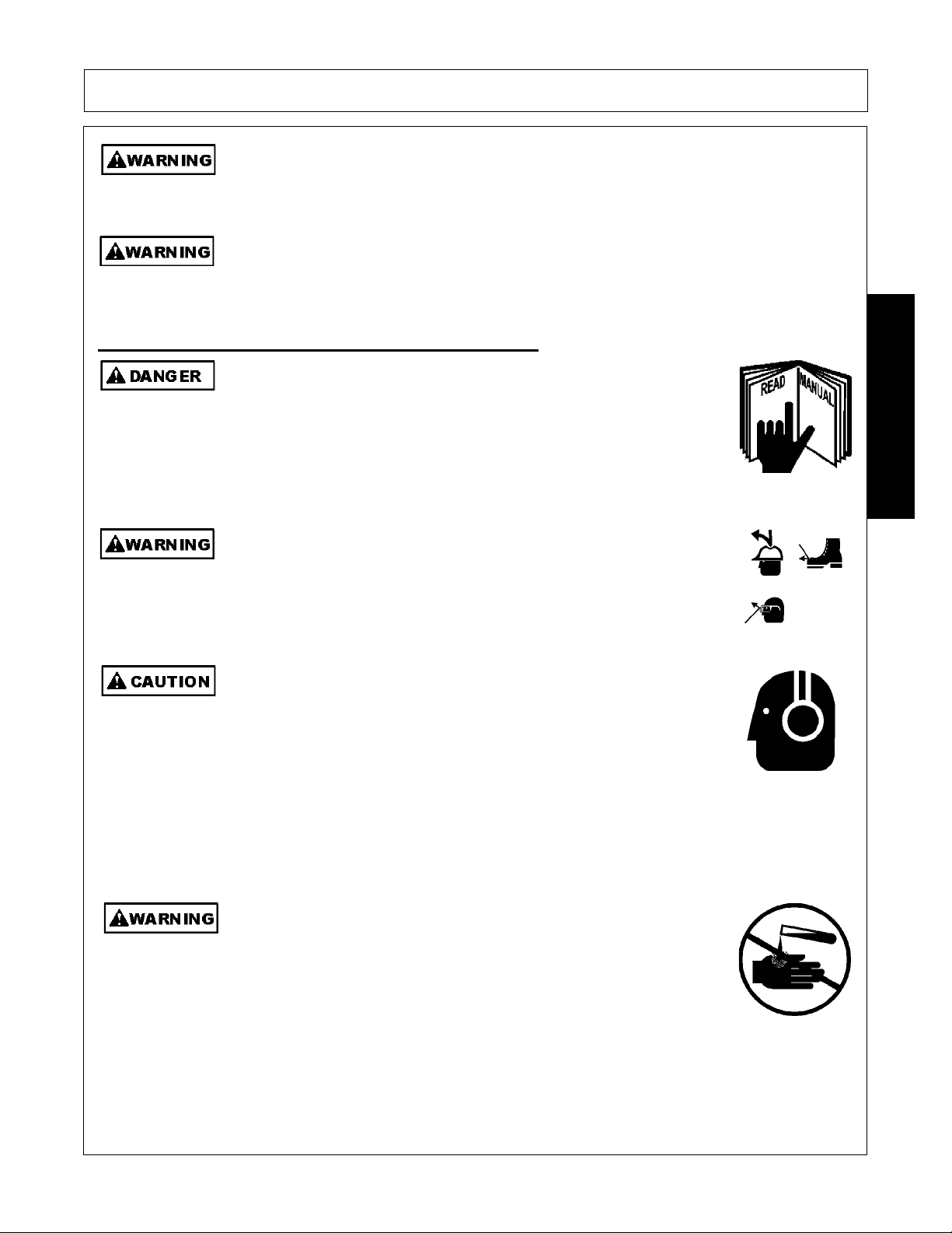
ever operate the Tractor or Implement un
completely understand this Manual, the Tractor Operator’s Manual, and
each of the Safety Messages found in the Manual or on the Tractor and
Implement. Learn how to stop the tractor engine suddenly in an
emergency. Never allow inexperienced or untrained personnel to
operate the Tractor or Implement without supervision. Make sure the
operator has fully read and understood the manuals prior to operation.
(SG-4)
The operator and all support personnel should wear hard hats, safety
shoes, safety glasses, and proper hearing protection at all times for
protection from injury including injury from items that may be thrown by
the equipment.
PROLONGED EXPOSURE TO LOUD NOISE MAY CAUSE
PERMANENT HEARING LOSS! Tractors with or without an Implement
attached can often be noisy enough to cause permanent hearing loss.
We recommend that you always wear hearing protection if the noise in
the Operator’s position exceeds 80db. Noise over 85db over an
extended period of time will cause severe hearing loss. Noise over 90db
adjacent to the Operator over an extended period of time will cause
permanent or total hearing loss. NOTE: Hearing loss from loud noise
[from tractors, chain saws, radios, and other such sources close to the
ear] is cumulative over a lifetime without hope of natural recovery.
(SG-16)
SAFETY
you have read an
(SG-I7)
ways read carefully and comply fully w
instructions when handling oil, solvents, cleansers, and any other
chemical agent.
2160 02/10 Safety Section 1-3
(SG-22)
© 2010 Alamo Group Inc.
e manufacturer’s
Page 10

SAFETY
Prol
U
tti
d
SAFETY
KEEP AWAY FROM ROTATING ELEMENTS to prevent entanglement
and possible serious injury or death.
Never allow children to play on or around Tractor or Implement. Children can slip or fall off
the Equipment and be injured or killed. Children can cause the Implement to shift or fall
crushing themselves or others.
NEVER use drugs or alcohol immediately before or while operating the
Tractor and Implement. Drugs and alcohol will affect an operator’s
alertness and coordination and therefore affect the operator’s ability to
operate the equipment safely. Before operating the Tractor or Implement,
an operator on prescription or over-the-counter medication must consult
a medical professional regarding any side effects of the medication that
would hinder their ability to operate the Equipment safely. NEVER
knowingly allow anyone to operate this equipment when their alertness or
coordination is impaired. Serious injury or death to the operator or others
could result if the operator is under the influence of drugs or alcohol.
(SG-24)
(SG-25)
(SG-27)
onged operation may cause operator boredom and fatigue affecting safe operation.
Take scheduled work breaks to help prevent these potentially impaired operating
conditions. Never operate the Implement and Tractor in a fatigued or bored mental state
which impairs proper and safe operation.
se extreme caution when ge
ng onto the Implement to perform repairs, maintenance an
(SG-32)
when removing accumulated material. Only stand on solid flat surfaces to ensure good
footing. Use a ladder or raised stand to access high spots which cannot be reached from
ground level. Slipping and falling can cause serious injury or death.
(SG-33)
Avoid contact with hot surfaces including hydraulic oil tanks, pumps, motors, valves and
hose connections. Relieve hydraulic pressure before performing maintenance or repairs.
Use gloves and eye protection when servicing hot components. Contact with a hot surface
or fluid can cause serious injury from burns or scalding.
(SG-34)
DO NOT operate this Implement on a Tractor that is not properly maintained. Should a
mechanical or Tractor control failure occur while operating, immediately shut down the
Tractor and perform repairs before resuming operation. Serious injury and possible death
could occur from not maintaining this Implement and Tractor in good operating condition.
(SG-36)
Avoid contact with hot surfaces of the engine or muffler. Use gloves and eye protection
when servicing hot components. Contact with a hot surface or fluid can cause serious injury
from burns or scalding.
(SG-38)
2160 02/10 Safety Section 1-4
© 2010 Alamo Group Inc.
Page 11

SAFETY
e
f
The rotating parts of this machine continue to rotate even after the Tractor has been turned
off. The operator should remain in his seat for 60 seconds after the brake has been set, the
PTO disengaged, the tractor turned off, and all evidence of rotation has ceased.
“Wait a minute...Save a life!”
Do not put hands or feet under mower decks. Blade Contact can result
in serious injury or even death. Stay away until all motion has stopped
and the decks are securely blocked up.
(SFL-2)
Do not put hands or feet under mower decks. Blade Contact can result
in serious injury or even death. Stay away until all motion has stopped
and the decks are securely blocked up.
(SGM-09)
Do not put hands or feet near the cutter bar. Blade contact can result
in serious injury. Stay away until all motion has stopped and the
mower is securely blocked up.
(SSM-1)
(SBM-5)
SAFETY
Do not operate the implement while wearing loose fitting clothing. Entanglement of th
clothing with the rotating elements can result in serious injury or even death. Stay clear o
all rotating elements at all times. (SSP-03)
Connecting & Disconnecting Implement Safety Instructions & Practices
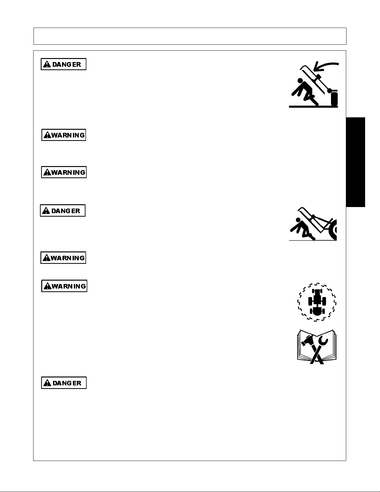
Each Rear Wheel must have a minimum of 1500 pound contact with the
surface to prevent lateral instability and possible tip-over which could
result in serious bodily injury or even death. Widen the wheel tread and
add weights if needed. Refer to the mounting instructions or call Customer Service if you
need assistance with Counterweight Procedure.
Do Not attempt to raise or lower the boom or mower head unless the Implement is securely
attached to the Tractor. The Implement could tip over and cause equipment damage and
possible serious injury or death. Do Not use the boom controls to assist in installing the
implement on the tractor. Raise or Lower the boom and mower head only while seated in
the Tractor operator’s seat with the seat belt securely fastened. Inadvertent contact with
the boom controls could allow a component to fall. A sudden or inadvertent fall by any of
these components could cause serious injury or even death.
(SBM-11)
(SBM-23)
2160 02/10 Safety Section 1-5
© 2010 Alamo Group Inc.
Page 12
SAFETY
Equipment Operation Safety Instructions and Practices
Never leave the Tractor and Implement unattended while the Implement is in the lifted
position. Accidental operation of lifting lever or a hydraulic failure may cause sudden drop
of unit with injury or death by crushing. To properly park the implement when disconnecting
it from the tractor, lower the stand and put the retaining pin securely in place, or put a secure
support under the A-Frame. Lower the implement carefully to the ground. Do not put hands
or feet under lifted components.
This Implement may be wider than the Tractor. Be careful when operating or transporting
this equipment to prevent the Implement from running into or striking sign posts, guard rails,
concrete abutments or other solid objects. Such an impact could cause the Implement and
Tractor to pivot violently resulting in loss of steering control, serious injury, or even death.
Never allow the Implement to contact obstacles.
(S3PT-1)
(S3PT-12)
SAFETY
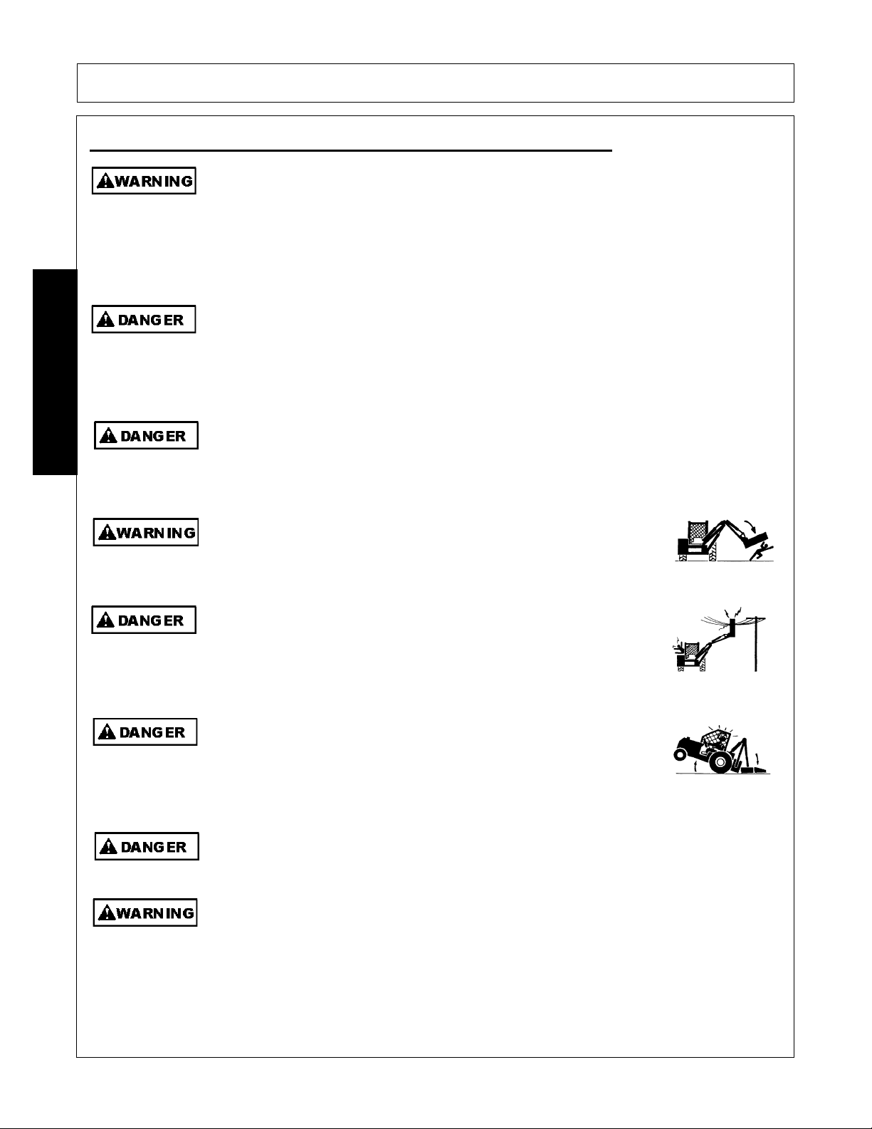
Use extreme caution when raising the Mower head. Stop the Blades from turning when the
Mower Head is raised and passersby are within 300 feet. Raising the Mower head
exposes the Cutting Blades which creates a potentially serious hazard and can cause
serious injury by objects thrown from the Blades or by contact with the Blades.
(SBM-2)
Never Leave the mower unattended while the head is in the raised
position. The mower could fall causing serious injury to anyone who
might inadvertently be under the mower
. (SBM-4)
Always keep a careful lookout and use extreme care when working
around overhead obstructions. Never allow the Mower head or boom
within 10 feet of any power line. When working close to overhead
power lines consult your electric company for a safe code of operation.
(SBM-7)
The center of Gravity of Tractors equipped with a Rear-Mounted Boom
Mower is shifted to the rear and removes weight from the front wheels.
Add front ballast until at least 20% of the tractors weight is on the front
wheels to prevent rearing up, loss of steering control, and possibly
injury.
(SBM-10)
The Mower shaft speed must not - UNDER ANY CIRCUMSTANCES - exceed 1800 RPM.
(SBM-15)
Use extreme care and Safety Awareness when using the boom mower head to mulch loose
brush or wood that has fallen on the ground from overhead trimming. DO NOT mulch this
debris if bystanders, vehicles, livestock or buildings are within 300 feet of the mower. This
cut debris can be thrown at great velocities and could result in serious injury or even death.
2160 02/10 Safety Section 1-6
© 2010 Alamo Group Inc.
(SBM-17)
Page 13
SAFETY
Do not back up this implement when the boom or mower head is extended. Backing could
damage the machine or its components.
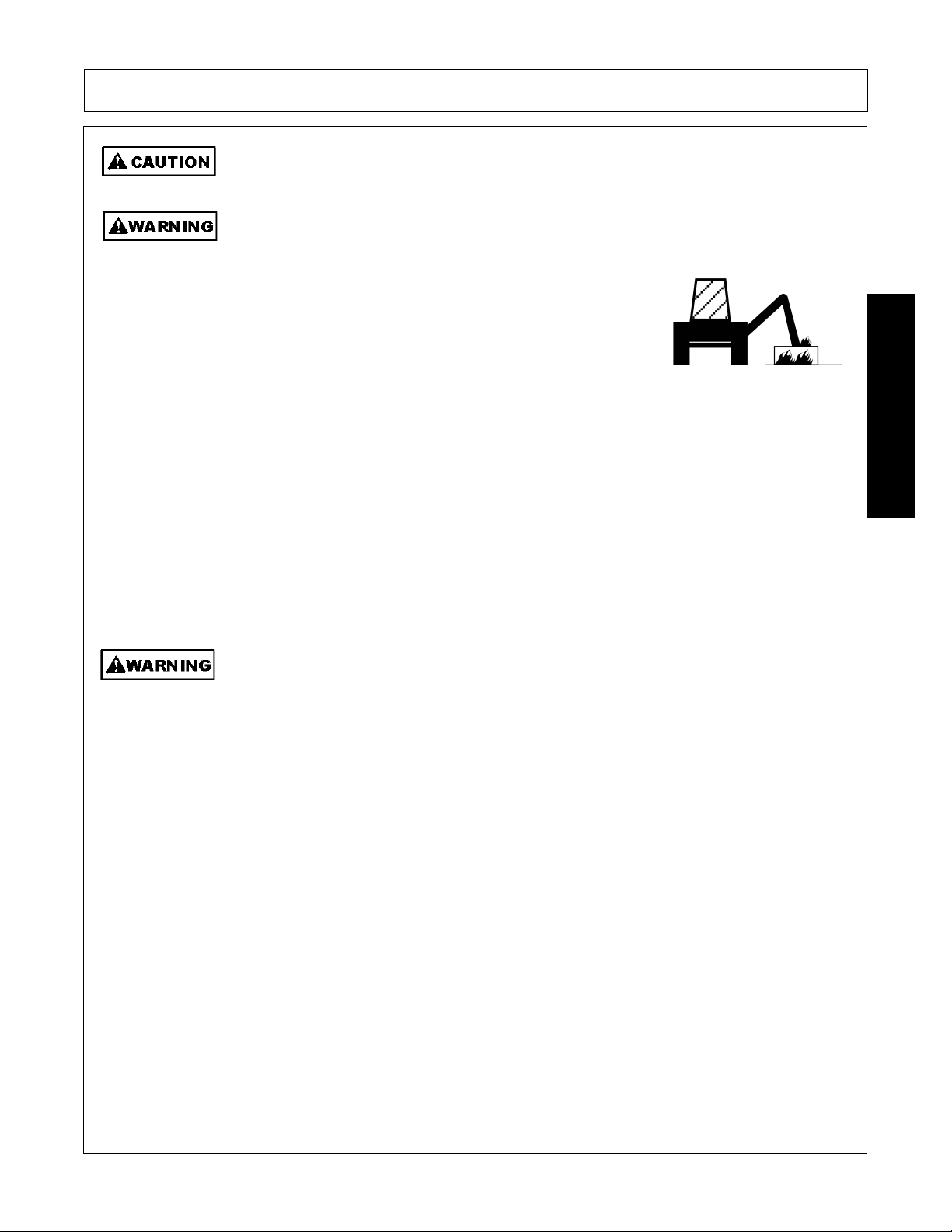
Follow these guidelines to reduce the risk of equipment and
grass fires while operating, servicing, and repairing the Mower
and Tractor:
-Equip the Tractor with a fire extinguisher in an accessible
location.
(SBM-19)
-Do Not operate the Mower on a Tractor with an underframe
exhaust.
-Do Not smoke or have an open flame near the Mower and
Tractor.
-Do Not drive into burning debris or freshly burnt areas.
-Do Not attempt to mow or place the mower head close to
burning debris.
-Never allow clippings or debris to collect near drivelines,
gearboxes or hydrualic componts such as valves, tanks,
pumps and motors. Periodically shut down the Tractor and
Mower and clean clippings and collected debris from the
mower deck.
Do not operate Mower if excessive vibration exists. Shut down PTO and the Tractor
engine. Inspect the Mower to determine the source of the vibration. If Mower blades are
missing or damaged replace them immediately. Do not operate the mower until the
blades have been replaced and the Mower operates smoothly. Operating the Mower with
excessive vibration can result in component failure and broken objects to be thrown
outward at very high velocities. To reduce the possibility of property damage, serious injury,
or even death, never allow the Mower to be operated with blades missing.
(SBM-20)
(SFL-4)
SAFETY
2160 02/10 Safety Section 1-7
© 2010 Alamo Group Inc.
Page 14
SAFETY
Flail M
diti
owers are capable under adverse con
ons of throwing
objects for great distances (300 feet or more) and causing serious
injury or death. Follow safety messages carefully.
STOP MOWING IF PASSERSBY ARE WITHIN 300 FEET UNLESS:
-Front and Rear Deflectors, Chain Guards, or Bands are installed and in good, workable
condition;
-Mower sections or Wings are running close to and parallel to the ground without
exposed Blades;
-All areas have been thoroughly inspected and all foreign material such as rocks, cans,
glass, and general debris has been removed.
NOTE: Where there are grass and weeds high enough to hide debris that could be
struck by the blades, the area should be: inspected and large debris removed, mowed at
an intermediate height, inspected closely with any remaining debris being removed, and
mowed again at desired final height. (This will also reduce power required to mow,
SAFETY
reduce wear and tear on the Mower drivetrain, spread cut material better, eliminate
streaking, and make the final cut more uniform.)
(SFL-6)
Operate this Equipment only with a Tractor equipped with an approved rollover-protective system (ROPS). Always wear seat belts. Serious injury or
even death could result from falling off the tractor--particularly during a turnover
when the operator could be pinned under the ROPS.
(SG-7)
BEFORE leaving the tractor seat, always set the parking brake and/or set
the tractor transmission in parking gear, disengage the PTO, stop the
engine, remove the key, and wait for all moving parts to stop. Place the
tractor shift lever into a low range or parking gear to prevent the tractor
from rolling. Never dismount a Tractor that is moving or while the engine
is running. Operate the Tractor controls from the tractor seat only.
Never allow children or other persons to ride on the Tractor or Implement.
Falling off can result in serious injury or death.
Never allow children to operate, ride on, or come close to the Tractor or
Implement. Usually, 16-17 year-old children who are mature and
responsible can operate the implement with adult supervision, if they
have read and understand the Operator’s Manuals, been trained in
proper operation of the tractor and Implement, and are physically large
enough to reach and operate the controls easily.
2160 02/10 Safety Section 1-8
(SG-9)
(SG-10)
(SG-11)
© 2010 Alamo Group Inc.
Page 15
SAFETY
I
difficul
k
Do not mount or dismount the Tractor while the tractor is moving. Mount
the Tractor only when the Tractor and all moving parts are completely
stopped.
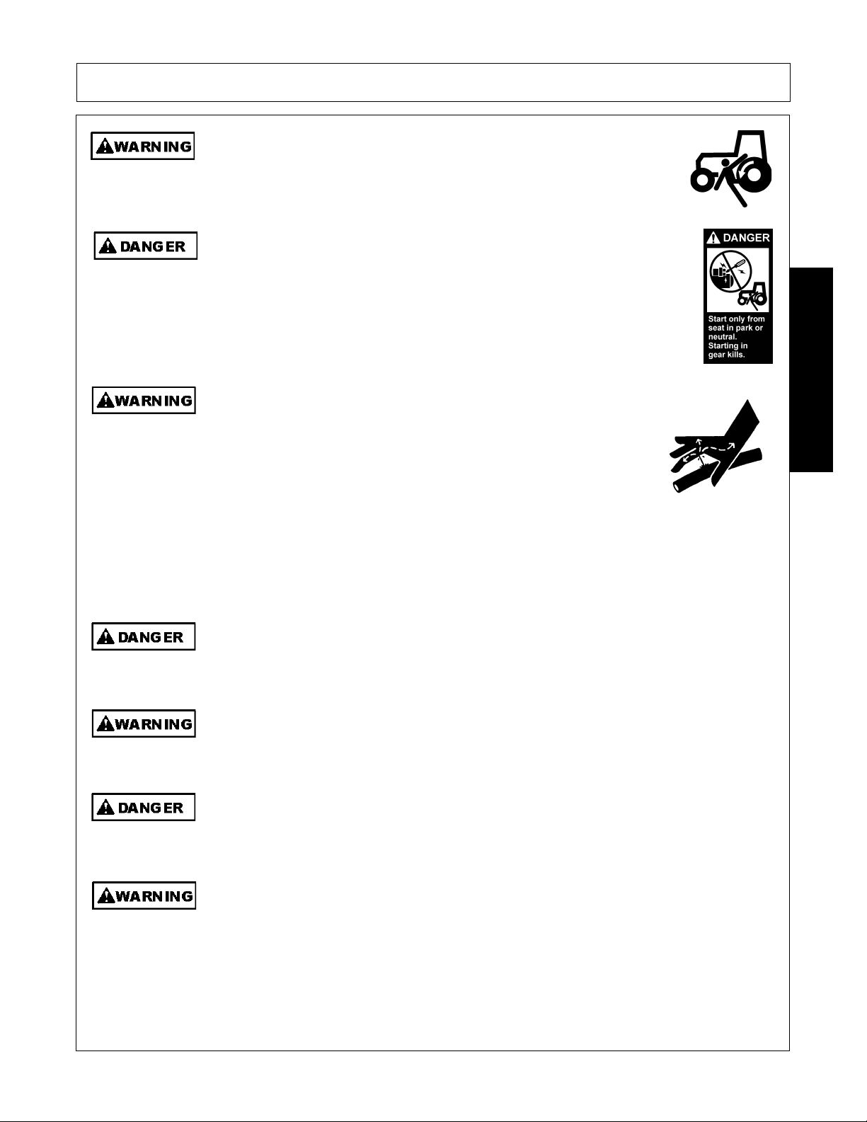
Start tractor only when properly seated in the Tractor seat. Starting a
tractor in gear can result in injury or death. Read the Tractor operators
manual for proper starting instructions.
Do not operate this Equipment with hydraulic oil or fuel leaking. Oil
and fuel are explosive and their presence could present a hazard. Do
not check for leaks with your hand! High-pressure oil streams from
breaks in the line could penetrate the skin and cause tissue damage
including gangrene. To check for a hose leak, SHUT the unit ENGINE
OFF and remove all hydraulic pressure. Wear oil impenetrable gloves,
safety glasses and use Cardboard to check for evidence of oil leaks. If
you suspect a leak, REMOVE the HOSE and have it tested at a Dealer.
If oil does penetrate the skin, have the injury treated immediately by a
physician knowledgeable and skilled in this procedure.
(SG-12)
(SG-13)
(SG-15)
SAFETY
Never run the Tractor engine in a closed building or without adequate ventilation. The
exhaust fumes can be hazardous to your health.
Do not exceed the rated PTO speed for the Implement. Excessive PTO speeds can cause
Implement driveline or blade failures resulting in serious injury or death.
Operate the Tractor and/or Implement controls only while properly seated in the Tractor seat
with the seat belt securely fastened around you. Inadvertent movement of the Tractor or
Implement may cause serious injury or death.
n case of mechanical
ty during operation, place the transmission in the par
position, set the parking brake, shut down all power, including the PTO and the engine and
remove the key. Wait until all rotating motion has stopped before dismounting.
2160 02/10 Safety Section 1-9
(SG-23)
(SG-26)
(SG-29)
(SG-39)
© 2010 Alamo Group Inc.
Page 16
SAFETY
E
h
M
Do Not operate this equipment in areas where insects such as bees may attack you and/or
cause you to lose control of the equipment. If you must enter in such areas, use a tractor
with an enclosed Cab and close the windows to prevent insects from entering. If a tractor
cab is not available, wear suitable clothing including head, face, and hand protection to
shield you from the insects. Attacking insects can cause you to lose control of the tractor,
which can result in serious injury or death to you or bystanders. Never dismount a moving
tractor.
Mow only in conditions where you have clear visibility in daylight or with adequate artificial
lighting. Never mow in darkness or foggy conditions where you cannot clearly see at least
300 feet (90 m) in front and to the sides of the tractor and mower. Make sure that you can
clearly see and identify passersby, steep slopes, ditches, drop-offs, overhead obstructions,
power lines, debris and foreign objects. If you are unable to clearly see these type of items
discontinue mowing.
(SG-40)
(SGM-1)
SAFETY
There are obvious and hidden potential hazards in the operation of this
Mower. REMEMBER! This machine is often operated in heavy brush
and in heavy weeds. The Blades of this Mower can throw objects if
shields are not properly installed and maintained. Serious injury or even
death may occur unless care is taken to insure the safety of the operator,
bystanders, or passersby in the area. Do not operate this machine with
anyone in the immediate area. Stop mowing if anyone is within 300 feet
of mower.
(SGM-02)
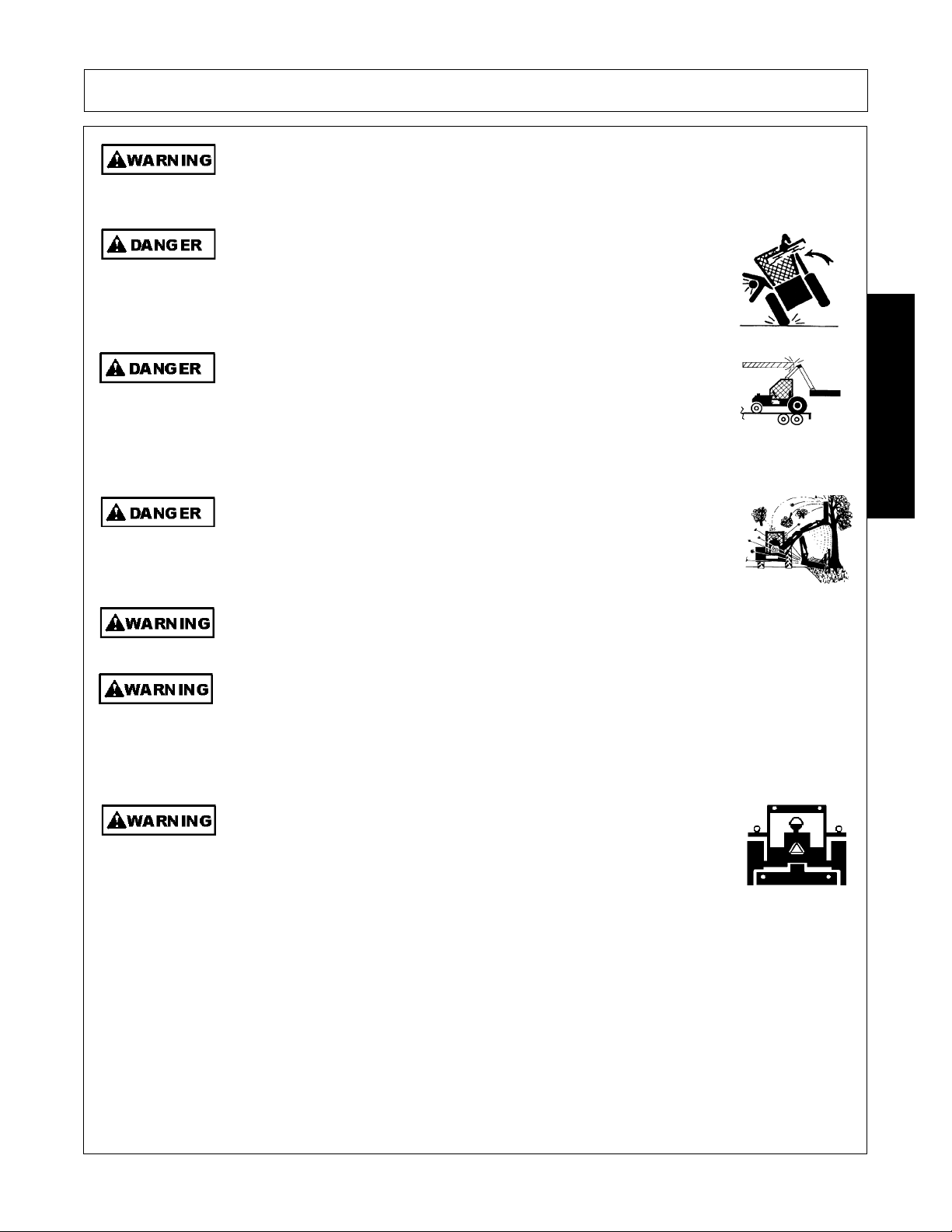
The rotating parts of this machine have been designed and tested for rugged use.
However, the blades could fail upon impact with heavy, solid objects such as metal guard
rails and concrete structures. Such impact could cause the broken objects to be thrown
outward at very high velocities. To reduce the possibility of property damage, serious
injury, or even death, never allow the cutting blades to contact such obstacles.
(SGM-4)
xtreme care should be taken when operating near loose objects suc
as gravel, rocks, wire, and other debris. Inspect the area before
mowing. Foreign objects should be removed from the site to prevent
machine damage and/or bodily injury or even death. Any objects that
cannot be removed must be clearly marked and carefully avoided by the
operator. Stop mowing immediately if blades strike a foreign object.
Repair all damage and make certain rotor or blade carrier is balanced
before resuming mowing.
(SGM-05)
any varied objects, such as wire, cable, rope, or chains, can become entangled in the
operating parts of the mower head. These items could then swing outside the housing at
greater velocities than the blades. Such a situation is extremely hazardous and could result
in serious injury or even death. Inspect the cutting area for such objects before mowing.
2160 02/10 Safety Section 1-10
Remove any like object from the site. Never allow the cutting blades to contact such items.
(SGM-06)
© 2010 Alamo Group Inc.
Page 17
SAFETY
M
The M
ifi
ow at the speed that you can safely operate and control the tractor and mower. The
correct mowing speed depends on terrain condition and grass type, density, and height of
cut. Normal ground speed range is from 2 to 5 mph(3-8 kph). Use slow mowing speeds
when operating on or near steep slopes, ditches, drop-offs, overhead obstructions, power
lines, or when debris and foreign objects are to be avoided.
Avoid mowing in reverse direction when possible. Check to make sure there are no
persons behind the mower and use extreme care when mowing in reverse. Mow only at a
slow ground speed where you can safely operate and control the tractor and mower.
Never mow an area that you have not inspected and removed debris or foreign material.
(SGM-08)
Do not mow with two machines in the same area except with Cab tractors with the windows
closed.
Follow these guidelines to reduce the risk of equipment and grass fires
while operating, servicing, and repairing the Mower and Tractor:
-Equip the Tractor with a fire extinguisher in an accesible location.
(SGM-11)
(SGM-07)
SAFETY
-Do Not operate the Mower on a Tractor with an underframe exhaust.
-Do Not smoke or have an open flame near the Mower and Tractor.
-Do Not drive into burning debris or freshly burnt areas.
-Ensure slip clutches are properly adjusted to prevent excessive slippage and plate heating.
-Never allow clippings or debris to collect near drivelines, slip clutches, and gearboxes.
Periodically shut down the Tractor and Mower and clean clippings and collected debris from
the mower deck.
(SGM-12)
ower is designed for certain mowing applications and is rated to cut up to a spec
size vegetation (see Mower Standard Equipment and Specifications). DO NOT use this
mower to cut vegetation above the Mower’s rated capacity or to cut any type of nonvegetative material. Only operate this Mower on a properly sized and equipped Tractor.
Operating this Mower in an application for which it is not designed and/or operating the
Mower with the wrong size Tractor can cause Mower component damage and equipment
failure resulting in possible serious injury or death.
(SGM-14)
Never leave the Implement and Power Unit unattended while the Implement is in the raised
position. Accidental operation of a lifting lever or a hydraulic failure may cause the
implement to suddenly fall causing serious injury or possible death to anyone who might
inadvertently be under the Implement. Lower the implement carefully to the ground. Do not
put hands or feet under lifted components.
(SPU-3)
c
2160 02/10 Safety Section 1-11
© 2010 Alamo Group Inc.
Page 18
SAFETY
Do not let the Blades turn when the Mower Deck is raised for any
reason, including clearance or for turning. Raising the Mower deck
exposes the Cutting Blades which creates a potentially serious hazard
and could cause serious injury or even death from objects thrown from
the Blades.
Maintenance and Service Safety Instructions and Practices
Make sure the PTO shield, integral driveline shields, and input shields
are installed when using PTO-driven equipment. Always replace any
shield if it is damaged or missing.
Always disconnect the main PTO Driveline from the Tractor before performing service on
the Implement. Never work on the Implement with the tractor PTO driveline connected and
SAFETY
running. Rotating Parts, Blades or Drivelines could turn without warning and cause
immediate entanglement, injury or death.
Never interfere with factory-set hydraulic calibrations. Any change in calibration could
cause a failure of the equipment and may result in injury.
(SRM-07)
(S3PT-8)
(S3PT-11)
(SBH-13)
Relieve hydraulic pressure prior to doing any maintenance or repair work on the Implement.
Place the Mower Head on the ground or securely supported on blocks or stands, disengage
the PTO, and turn off the engine. Push and pull the control Levers or Joystick several times
to relieve pressure prior to starting any maintenance or repair work.
(SBM-6)
Always disconnect the wire leads from the mower pump solenoid
before performing service on the Tractor or Mower. Use caution when
working on the Tractor or Mower. Tractor engine must be stopped
before working on Mower or Tractor. The Mower Blades could inadvertently be turned on
without warning and cause immediate dismemberment, injury or death.
(SBM-12a)
All Safety Shields, Guards and Safety devices including (but not
limited to) - the Deflectors, Chain Guards, Steel Guards,
Gearbox Shields, PTO integral shields , and Retractable Door
Shields should be used and maintained in good working condition. All safety
devices should be inspected carefully at least daily for missing or broken
components. Missing, broken, or worn items must be replaced at once to reduce
the possibility of injury or death from thrown objects, entanglement, or blade
contact.
(SBM-18)
2160 02/10 Safety Section 1-12
© 2010 Alamo Group Inc.
Page 19
SAFETY
DO NOT allow any person under a raised boom or mower head unless
it is securely locked up or supported. DO NOT approach the
Implement unless the Tractor is turned off and all motion has ceased.
Never work under the frame work, or any lifted component unless the implement is
securely supported or blocked up. Inadvertent contact with the controls could allow a
component to fall. A sudden or inadvertent fall by any of these components could cause
serious injury or even death.
(SBM-22)
Always maintain the safety signs in good readable condition. If the safety signs are missing,
damaged, or unreadable, obtain and install replacement safety signs immediately.
(SG-5)
Do not modify or alter this Implement. Do not permit anyone to modify or alter this
Implement, any of its components or any Implement function.
(SG-8)
Never work under the Implement, the framework, or any lifted
component unless the Implement is securely supported or blocked up
to prevent sudden or inadvertent falling which could cause serious
injury or even death.
(SG-14)
Never attempt to lubricate, adjust, or remove material from the Implement while it is in
motion or while tractor engine is running.
(SG-20)
Periodically inspect all moving parts for wear and replace when
necessary with authorized service parts. Look for loose fasteners, worn
or broken parts, and leaky or loose fittings. Make sure all pins have
cotter pins and washers. Serious injury may occur from not maintaining
this machine in good working order.
(SG-21)
SAFETY
Do Not fill fuel tank while engine is running. Refuel only after engine has cooled down. If
fuel is spilled, move machine away from the area of the spill and avoid creating any source
of ignition until the gasoline has evaporated.
2160 02/10 Safety Section 1-13
© 2010 Alamo Group Inc.
(SG-28)
Page 20

SAFETY
U
dli
r
Perform service, repairs and lubrication according to the maintenance section. Ensure the
unit is properly lubricated as specified in the lubrication schedule and all bolts and nuts are
properly torqued. Failure to properly service, repair and maintain this Implement in good
operating condition could cause component failure and possible serious injury or even
death.
(SG-35)
se caution and wear protective gloves when han
ng sharp objects such as blades,
knives, and other cutting edges. Be alert to worn component surfaces which have sharp
edges. Sharp surfaces can inflict severe laceration injuries if proper hand protection is not
worn.
(SG-37)
Replace bent or broken blades with new blades. NEVER ATTEMPT TO STRAIGHTEN,
WELD, OR WELD HARDFACING ON BLADES SINCE THIS WILL LIKELY CRACK OR
OTHERWISE DAMAGE THE BLADE WITH SUBSEQUENT FAILURE AND POSSIBLY
SAFETY
CAUSE SERIOUS INJURY FROM THROWN BLADES.
(SGM-10)
DO NOT weld or repair rotating mower components. Welds and other repairs may cause
severe vibration and/or component failure resulting in part being thrown from the mower
causing serious bodily injury. See your Authorized Dealer for proper repairs.
(SGM-13)
PARTS INF O RMATION
Rhino mowers use balanced and matched system components for blade carriers, blades, cuttershafts, knives,
knife hangers, rollers, drivetrain components, and bearings. These parts are made and tested to Rhino specifications. Non-genuine "will fit" parts do not consistently meet these specifications. The use of “will fit” parts
may reduce mower performance, void warranties, and present a safety hazard. Use genuine Rhino mower
parts for economy and safety.
(SPRM-1)
SEE YOUR RHINO DEALER
Transporting Safety Instructions and Practices
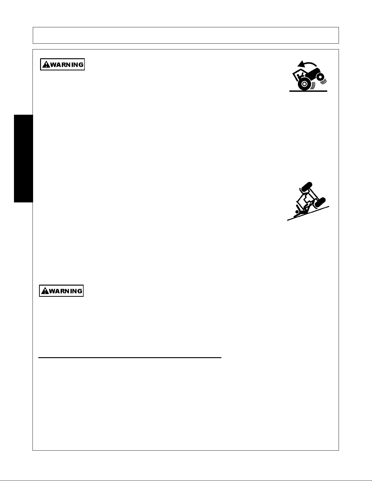
Be particularly careful when transporting the Implement with the Tractor. Turn curves or go
up hills only at a low speed and using a gradual steering angle. Rear mounted implements
move the center of gravity to the rear and remove weight from the front wheels. Make
certain, by adding front ballast, that at least 20% of the tractor’s weight is on the front wheels
to prevent rearing up, loss of steering control or Tractor tip-over. Slow down on rough o
uneven surfaces to prevent loss of steering control which could result in property damage
or possible injury. Do not transport unless 3-Point lift lever is fully raised and in the latched
transport position. Dropping implement in transport can cause serious damage to the
tractor and/or Implement and possibly cause the operator or others to be injured or killed.
(S3PT-02)
2160 02/10 Safety Section 1-14
© 2010 Alamo Group Inc.
Page 21
SAFETY
Allow sufficient clearance for the Implement to swing outward while turning. Implements
carried behind the Tractor will swing outside the tire path when making turns. Contacting a
solid object while turning will cause equipment damage and possible injury.
Be particularly careful in transport. The Mower has raised the center of
gravity for the tractor and has increased the possibility of overturn.
Turn curves or go up slopes only at low speed and using a gradual
turning angle. Slow down on rough or uneven surfaces.
When transporting Boom Mower on a truck or trailer, the height or width
may exceed legal limits when the boom is in the transport position.
Contact with side or overhead structures or power lines can cause
property damage or serious injury or death. If necessary lower boom to
reduce height and/or remove mowing head to reduce width to the legal
limits.
(SBM-8)
Never operate the Tractor and Mower Unit without an OPS (Operators
Protective Structure) or Cab to prevent injury from objects thrown from
ground or from overhead trimming. Stop mowing if workers or passersby
are within 300 feet.
(SBM-9)
(S3PT-20)
(SBM-3)
SAFETY
The Joystick Master Control Switch must be OFF to prevent accidental movement of the
boom and cutting head whenever the mower is not being operated.
(SBM-16)
Secure the boom and mower head in the transport position before traveling on public roads.
Never transport on public roads with the boom and mower head extended. Always
disengage and lock out the hydraulic controls for the boom mower before transporting.
Inadvertent boom movement on public roads may contact with other vehicles resulting in
serious bodily injuries or even death.
(SBM-21)
Make certain that the “Slow Moving Vehicle” (SMV) sign is installed in
such a way as to be clearly visible and legible. When transporting the
Equipment use the Tractor flashing warning lights and follow all local
traffic regulations.
(SG-6)
2160 02/10 Safety Section 1-15
© 2010 Alamo Group Inc.
Page 22
SAFETY
Transport only at speeds where you can maintain control of the
equipment. Serious accidents and injuries can result from operating this
equipment at high speeds. Understand the Tractor and Implement and how it handles
before transporting on streets and highways. Make sure the Tractor steering and brakes
are in good condition and operate properly.
Before transporting the Tractor and Implement, determine the proper transport speeds for
you and the equipment. Make sure you abide by the following rules:
Test the tractor at a slow speed and increase the speed slowly. Apply the Brakes smoothly
to determine the stopping characteristics of the Tractor and Implement. As you increase
the speed of the Tractor the stopping distance increases. Determine the maximum
transport speed not to exceed 20 mph (30 kph) for transporting this equipment.
Test the equipment at a slow speed in turns. Increase the speed through the turn only after
you determine that the equipment can be operated at a higher speed. Use extreme care
SAFETY
and reduce your speed when turning sharply to prevent the tractor and implement from
turning over. Determine the maximum turning speed for you and this equipment before
operating on roads or uneven ground.
Only transport the Tractor and Implement at the speeds which allow you to properly control
the equipment.
Be aware of the operating conditions. Do not operate the Tractor with weak or faulty brakes
or worn tires. When operating down a hill or on wet or rain slick roads, the braking distance
increases: use extreme care and reduce your speed. When operating in traffic always use
the Tractor’s flashing warning lights and reduce your speed. Be aware of traffic around you
and watch out for the other guy.
Your driving vision may be reduced or impaired by the tractor, cab, or implement. Before
driving on public roadways identify any limited vision areas, and make adjustments to your
operating position, mirrors, and the implement transport position so that you can clearly
see the area where you will be traveling, and any traffic that may approach you. Failure to
maintain adequate vision of the public roadway and traffic can result in serious injury or
even death.
(SG-19)
(STI-10)
Concluding Safety Instructions and Practices
In addition to the design and configuration of this Implement, including Safety Signs and Safety Equipment,
hazard control and accident prevention are dependent upon the awareness, concern, prudence, and proper
training of personnel involved in the operation, transport, maintenance, and storage of the machine. Refer
also to Safety Messages and operation instruction in each of the appropriate sections of the Tractor and
Equipment Manuals. Pay close attention to the Safety Signs affixed to the Tractor and Equipment.
(SG-18)
2160 02/10 Safety Section 1-16
© 2010 Alamo Group Inc.
Page 23

SAFETY
Decal Location
NOTE: Rhino supplies safety decals on this product to promote safe operation. Damage to the decals may
occur while in shipping, use, or reconditioning. Rhino cares about the safety of its customers, operators, and
bystanders, and will replace the safety decals on this product in the field, free of charge (Some shipping and
handling charges may apply). Contact your Rhino dealer to order replacement decals.
SAFETY
2160 02/10 Safety Section 1-17
© 2010 Alamo Group Inc.
Page 24

SAFETY
ITEM PART NO. QTY LEVEL DESCRIPTION
1. D389 1 DANGER Multi-Hazard
2. D388 1 DANGER Multi-Hazard
3. D401 1 WARNING 1000 RPM (Not Shown-Apply to D388
if 1000 RPM)
4. 02962764 2 WARNING Pinch Points
5. D416 1 IMPORTANT Service Hydraulic System
6. 02962765 1 DANGER Crushing and Pinch Points
7. 999001 1 WARNING Tractor Safety
8. 00753840 1 DANGER Stay Clear when Lowering Wing
9. 02965262 1 WARNING Oil Leaks
10. 02958241 1 DANGER Boom Safety
11. 00760657 1 IMPORTANT Genuine Rhino Parts
SAFETY
12. D303 2 NAME LOGO RHINO Name
13. 00764866 4 NAME LOGO Servis 2160 Name
14. D302 1 LOGO Rhino Logo (Small)
15. D304 2 LOGO Rhino Logo (Big)
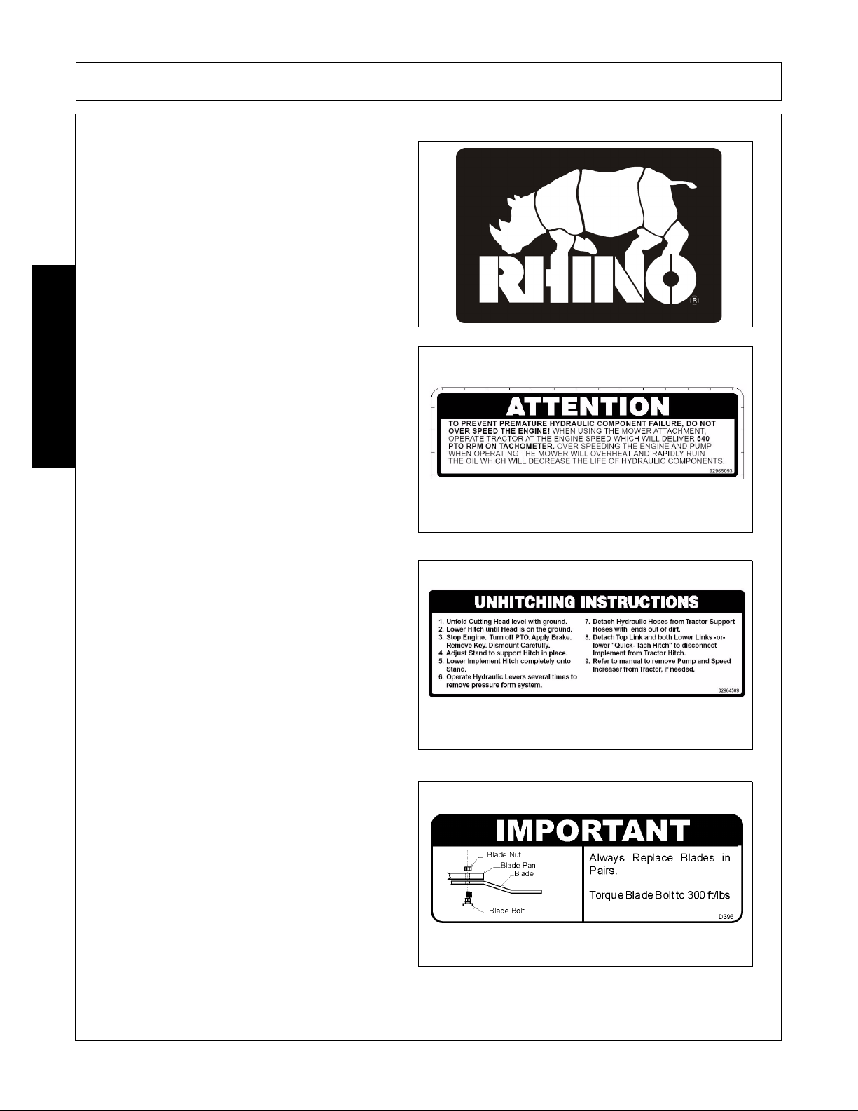
16. 02965093 1 ATTENTION Do not Overspeed Engine
17. 02964509 2 INSTRUCT Unhitching Instructions
18. D395 1 IMPORTANT Replace Blades in Pairs
19. NFS 1 SER PLT Serial Number (Not Shown)
20. 1458392 1 REFLECT Red Reflector
21. 1458393 1 REFLECT Yellow Reflector
22. 03200347 * REFLECT SMV Sign
23. 00776031 1 ________ Canister
24. 10058000 3 ________ Bolt
25. 00024100 3 ________ Flatwasher
26. 02959924 3 ________ Locknut
27. 000678 2 INFO Grease Fitting Inside
2160 02/10 Safety Section 1-18
© 2010 Alamo Group Inc.
Page 25
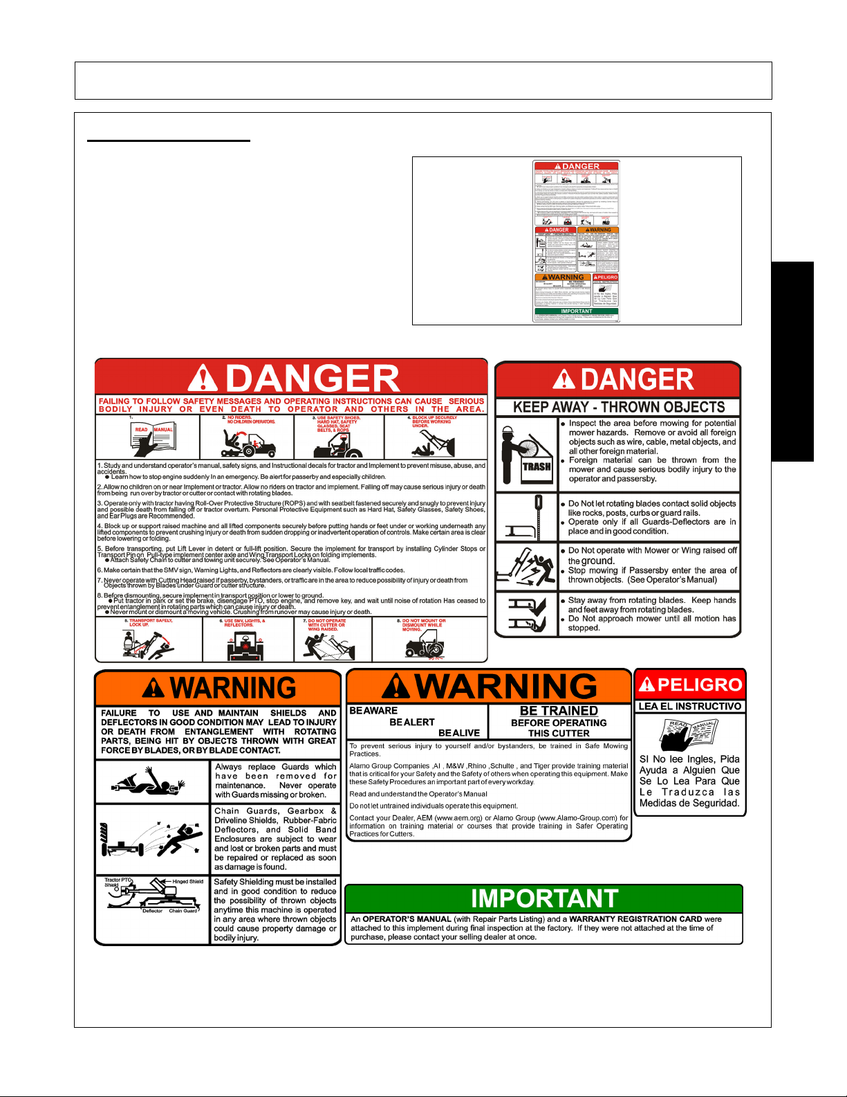
Decal Description
Multi Hazard Decal Sheet
SAFETY
P/N D389
Decal D389 consists of the following multi-hazards.
SAFETY
2160 02/10 Safety Section 1-19
© 2010 Alamo Group Inc.
Page 26
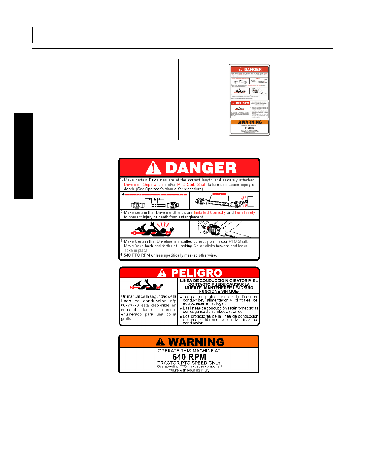
Driveline Hazards
P/N D388
Decal D388 consists of the following multi-hazards.
SAFETY
SAFETY
2160 02/10 Safety Section 1-20
© 2010 Alamo Group Inc.
Page 27
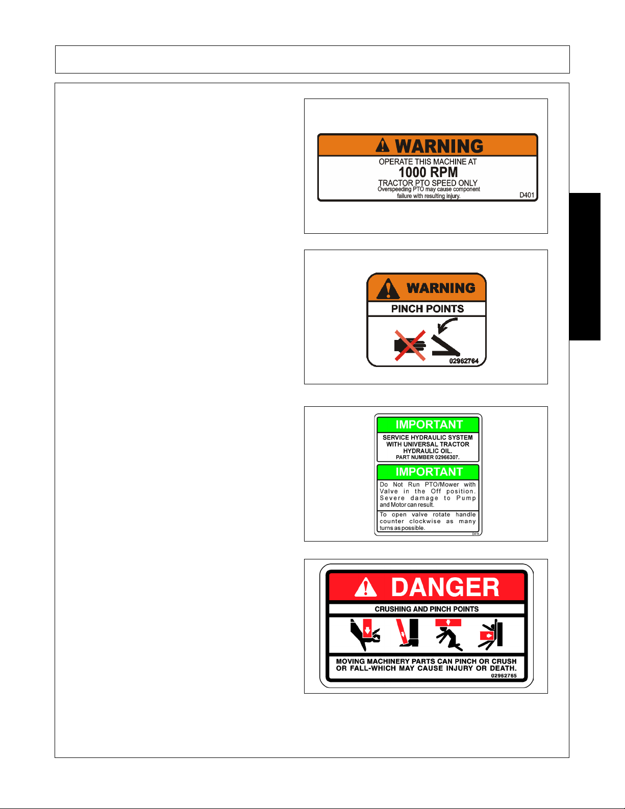
1000 RPM
SAFETY
P/N D401
WARNING! Pinch Points
P/N 02962764
IMPORTANT - Service Hydraulic System with
Universal Tractor Hydraulic Oil.
SAFETY
P/N D416
DANGER! Crushing and Pinch Points.
Moving machinery parts can pinch or crush or fallwhich may cause injury or death.
P/N 02962765
2160 02/10 Safety Section 1-21
© 2010 Alamo Group Inc.
Page 28
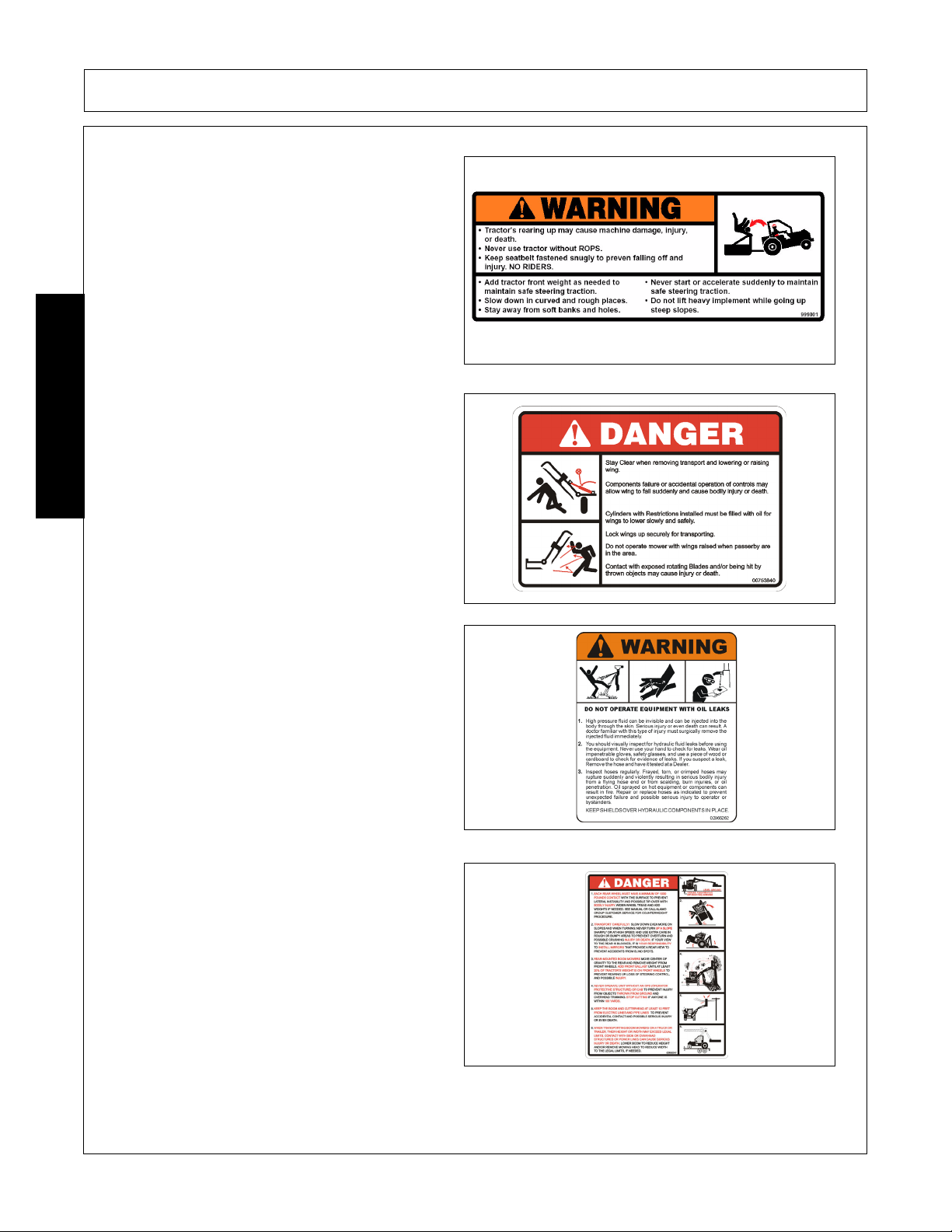
WARNING! Tractor rearing
P/N 999001
DANGER! Stay clear when lowering or raising
wings.
SAFETY
SAFETY
P/N 00753840
WARNING! Failure to INSPECT and REPAIR or
REPLACE Hoses may allow worn Hoses to rupture
SUDDENLY and VIOLENTLY with resulting serious
BODILY INJURY from SCALDING or FIRE with
resulting BURN INJURY or DEATH.
P/N 02965262
DANGER! - Multi-Hazard Boom. Take precautions
while transporting and operating Boom Unit.
P/N 02958241
2160 02/10 Safety Section 1-22
© 2010 Alamo Group Inc.
Page 29

SAFETY
For safety and to guarantee optimum product
reliability always use genuine RHINO replacement
parts.
P/N 00760657
Logo Product Name: Rhino
P/N D303
NAME LOGO - Servis 2160
SAFETY
00764866
Logo Product Name: Rhino
P/N D302
2160 02/10 Safety Section 1-23
© 2010 Alamo Group Inc.
Page 30
Logo Name: RHINO
P/N D304
INFORMATION - To prevent premature hydraulic
component failure, do not over speed the engine.
When using the mower attachment, operate tractor
at the engine speed which will deliver 540 PTO
SAFETY
RPM on Tachometer. Over speeding the engine
and pump when operating the mower will overheat
and rapidly ruin the oil which will decrease the life
of the hydraulic components.
SAFETY
P/N 02965093
INFORMATION - Unhitching Instructions
02964509
IMPORTANT! Always replace blades in pairs.
P/N D395
2160 02/10 Safety Section 1-24
© 2010 Alamo Group Inc.
Page 31

SAFETY
Red Reflector. Keep reflectors clean and visible.
P/N 1458392
Amber Reflector. Keep reflectors clean and visible.
P/N 1458393
Slow Moving Vehicle Decal. Keep SMV reflector
clean and visible. DO NOT transport or operate
without the SMV.
SAFETY
P/N 03200347
Read Operator’s Manual! The operator’s manual is
located inside this canister. If the manual is
missing order one from your dealer.
P/N 00776031
2160 02/10 Safety Section 1-25
© 2010 Alamo Group Inc.
Page 32

Information that Grease Fitting is present and must
apply grease
P/N 000678
SAFETY
SAFETY
2160 02/10 Safety Section 1-26
© 2010 Alamo Group Inc.
Page 33

SAFETY
Federal Laws and Regulations
This section is intended to explain in broad terms the concept and effect of federal laws and regulations
concerning employer and employee equipment operators. This section is not intended as a legal
interpretation of the law and should not be considered as such.
Employer-Employee Operator Regulations
U.S. Public Law 91-596 (The Williams-Steiger Occupational and Health Act of 1970) OSHA
This Act Seeks:
“...to assure so far as possible every working man and woman in the nation safe and healthful working
conditions and to preserve our human resources...”
DUTIES
Sec. 5 (a) Each employer-
(1) shall furnish to each of his employees employment and a place of employment which are free from
recognized hazards that are causing or are likely to cause death or serious physical harm to his employees;
(2) shall comply with occupational safety and health standards promulgated under this Act.
(b) Each employee shall comply with occupational safety and health standards and all rules, regulations and
orders issued pursuant to this Act which are applicable to his own actions and conduct.
OSHA Regulations
OSHA regulations state in part: “At the time of initial assignment and at least annually thereafter, the employer
shall instruct every employee in the safe operation and servicing of all equipment with which the employee is,
or will be involved.”
Employer Responsibilities:
SAFETY
To ensure employee safety during Tractor and Implement operation, it is the employer’s responsibility to:
1. Train the employee in the proper and safe operation of the Tractor and Implement.
2. Require that the employee read and fully understand the Tractor and Implement Operator’s manual.
3. Permit only qualified and properly trained employees to operate the Tractor and Implement.
4. Maintain the Tractor and Implement in a safe operational condition and maintain all shields and guards on the
equipment.
5. Ensure the Tractor is equipped with a functional ROPS and seat belt and require that the employee operator
securely fasten the safety belt and operate with the ROPS in the raised position at all times.
6. Forbid the employee operator to carry additional riders on the Tractor or Implement.
7. Provide the required tools to maintain the Tractor and Implement in a good safe working condition and provide the
necessary support devices to secure the equipment safely while performing repairs and service.
8. Require that the employee operator stop operation if bystanders or passersby come within 25 feet.
Child Labor Under 16 Years of Age
Some regulations specify that no one under the age of 16 may operate power machinery. It is your
responsibility to know what these regulations are in your own area or situation. (Refer to U.S. Dept. of
Labor, Employment Standard Administration, Wage & Home Division, Child Labor Bulletin #102.)
2160 02/10 Safety Section 1-27
© 2010 Alamo Group Inc.
Page 34

Page 35

Page 36

Page 37

Page 38

Page 39

Page 40

Page 41

Page 42

Page 43

Page 44

Page 45

Page 46

Page 47

Page 48

Page 49

Page 50

Page 51

Page 52

Page 53

Page 54

Page 55

Page 56

Page 57

Page 58

Page 59

Page 60

Page 61

Page 62

Page 63

Page 64

Page 65

Page 66

Page 67

Page 68

Page 69

Page 70

Page 71

Page 72

Page 73

Page 74

Page 75

Page 76

Page 77

Page 78

Page 79

INTRODUCTION SECTION
© 2010 Alamo Group Inc.
Introduction Section 2-1
Page 80

INTRODUCTION
This Boom Mower is designed with care and built with quality materials by skilled workers. Proper assembly,
maintenance, and operating practices, as described in this manual, will help the owner/operator get years of
satisfactory service from the machine.
The purpose of this manual is to familiarize and instruct. The Assembly Section instructs the owner/operator in
the correct assembly of the Mower using standard and optional equipment. The Parts Listing section is
designed to familiarize the owner/operator with replaceable parts on the Mower. This section provides
exploded assembly drawings of each mower component illustrating each piece and the corresponding part
number.
Careful use and timely service saves extensive repairs and costly downtime losses. The Operation and
Maintenance Sections of the manual train the owner/operator how to work the Mower correctly and attend to
appropriate maintenance. The Trouble Shooting Guide helps diagnose difficulties with mower and offers
solution to the problems.
Safety is of primary importance to the owner/operator and to the manufacturer. The first section of this manual
includes a list of Safety Messages, that, if followed, will help protect the operator and bystanders from injury or
death. Many of the Safety Messages will be repeated throughout the manual. The owner/operator/dealer
INTRODUCTION
should know these Safety Messages before assembly and be aware of the hazards of operating this mower
during assembly, use, and maintenance. The Safety Alert Symbol combined with a Signal Word, as seen
below, is intended to warn the owner/operator of impending hazards and the degree of possible injury faced
when operating this machine.
Indicates an imminently hazardous situation that, if not avoided, WILL result in DEATH OR
VERY SERIOUS INJURY.
Indicates an imminently hazardous situation that, if not avoided, COULD result in DEATH
OR SERIOUS INJURY.
Indicates an imminently hazardous situation that, if not avoided, MAY result in MINOR
INJURY.
Identifies special instructions or procedures that, if not strictly observed, could result in
damage to, or destruction of the machine, attachments or the environment.
2160 02/10 Introduction Section 2-2
© 2010 Alamo Group Inc.
Page 81

INTRODUCTION
INTRODUCTION
The 2160 is ideal for mowing pond embankment levee or drainage ditches, and cutting overhanging limbs on
fence rows.
For Non-Agricultural use, OSHA, ASAE, SAE, and ANSI standards require the use of Chain
Guards, Deflectors, or Solid Skirts at all times. The Mower manufacturer strongly
recommends the use of Chain Guards or Rubber Deflectors for Agricultural purposes as
well, to reduce the risk of property damage, serious bodily injury, or even death from objects
thrown out by or from contact with the Cutting Blades.
At least 20% or the tractor’s weight must be on the front tires with the Mower lifted to provide
adequate traction for safe steering under good conditions. Slow down on hills, rough terrain,
and curves.
2160 02/10 Introduction Section 2-3
© 2010 Alamo Group Inc.
Page 82

INTRODUCTION
Attention Owner/Operator
BEFORE OPERATING THIS MACHINE:
1. Carefully read the Operator’s Manual, completely understand the Safety Messages and instructions, and
know how to operate correctly both the tractor and implement.
2. Fill out the Warranty Card in full. Be sure to answer all questions, including the Serial Number of the
implement. Mail within 30 days of delivery date of this implement.
NOTE: Warranties are honored only if completed “Owner Registration and Warranty” forms are received by
Alamo Group within thirty days of delivery of the implement.
3. Record the Mower Model and Serial Numbers on the Warranty page at the front of the Operator’s Manual.
Keep this as part of the permanent maintenance file for the implement.
INTRODUCTION
2160 02/10 Introduction Section 2-4
© 2010 Alamo Group Inc.
Page 83

ASSEMBLY SECTION
© 2010 Alamo Group Inc.
Assembly Section 3-1
Page 84

ASSEMBLY
TRACTOR PREPARATION
1. Move left rear tire out so that it is 50 inches minimum from the outside of left rear tire to the center of tractor. Then move the right rear tire out so that it is 96 inches minimum between the outside of the left and
right rear tires. Refer to your tractor’s Operator’s Manual for instructions on Rear Wheel Adjustment for
your particular tire. Asm-B-0029. Install fluid ballast inn left rear tire as needed for stability. Check tractor
manual for recommended procedure and limits.
2. Extend front wheels out so that it is 55" inches between the inside of the tires. Asm-B-0030.
ASSEMBLY
Never operate the tractor with a loose wheel rim or disc. Always tighten nuts to the specified
torque and at the recommended intervals.
3. Install 00749117 Safety Decal on left fender or elsewhere clearly in operator’s view.
2160 02/10 Assembly Section 3-2
© 2010 Alamo Group Inc.
Page 85

ASSEMBLY
MOWER TO TRACTOR ATTACHMENT
This mower is designed for 540 or 1000 RPM PTO with CAT II or CAT III Quick Hitch (Standard) or CAT II or
CAT III 3-Point Hitch (Optional).
CAT II and III Quick Hitch ( Standard) (Asm-B-0031)
Back-up tractor with Quick Hitch and align bottom lugs (1) of hitch to lower lugs (2) of frame. Then raise lift
arms until Pins (3) lock into lower lugs (1). Top lug (4) on Quick Hitch should simultaneously hitch to Pin (5) on
top of Rhino Boom Frame.
ASSEMBLY
CAT II and III 3-Point Hitch (Optional Equipment)
Attach the lower hitch arms to the lower lugs of the frame and attach the top link to the tractor. The Hydraulic
Relief Arm (Optional Equipment) is required for attaching the 2160 to a tractor not equipped with a quick hitch.
When using this type of hitch it should be the last thing assembled. Instructions for this hitch will be later in this
section (pages 3-12).
NOTE: Once unit is attached to the tractor be sure to remove the shipping pallet.
2160 02/10 Assembly Section 3-3
© 2010 Alamo Group Inc.
Page 86

ASSEMBLY
DRIVELINE LENGTH CHECK PROCEDURE
Before using mower check driveline length with tractor attached to mower.
1. Separate two halves of driveline and connect one half to tractor and the other half to mower.
2. Lower mower to normal operating position.
3. Bring the two driveline halves together as shown in figure 6. At this maximum compressed length there
should be 1-1/2 inches or more clearance from tubes bottoming out. If not, shorten the driveline to obtain
clearance. Shorten shield tubes and sliding profiles by the same amount. Round off all sharp edges and
remove burrs. Grease the sliding profiles.
4. Raise mower to transport position. Check driveline length at this maximum extension to make sure profile
tubes are always engaged at least 8 inches.
When attaching PTO yoke to tractor PTO shaft, it is important that spring activated locking
collar slides freely and is seated in groove in PTO shaft.
ASSEMBLY
Be sure PTO shielding and all other shielding is installed and is in good condition.
2160 02/10 Assembly Section 3-4
© 2010 Alamo Group Inc.
Page 87

ASSEMBLY
HOSE CONNECTION
When assembling the fittings and hoses, be careful not to introduce any dust or contaminants into the system.
Keep all fittings, hoses and hydraulic components sealed until installed. Do not allow any components to lie
open and exposed to dust or contamination. Do not lay parts down on the dirt or sand and then assemble them
as this will introduce contaminants into the system.
To avoid Hydraulic Contamination, always keep all hoses and hydraulic fittings capped until they are ready to
be installed. Asm-B-0006.
ASSEMBLY
2160 02/10 Assembly Section 3-5
© 2010 Alamo Group Inc.
Page 88

ASSEMBLY
ATTACHMENT OF HYDRAULIC HOSES
It is important that pipe thread sealant be used only on pipe threads; never on 37 degree flared fitting or on
straight thread “O” ring fittings. Use the pipe thread sealant supplied. Do not substitute with some other type of
sealant, such as, teflon tape, paint, shellac, etc.
Hoses supplied have two types of fittings; solid or swivel. Some hoses have solid fittings on both ends; others
have a solid fitting and a swivel fitting. Hoses with two solid fittings will fit into either an internal solid thread or a
swivel adapter union. When installing either type hose, solid fittings must be installed first, then install the
swivel end of the hose or fitting.
The hydraulic system incorporates three basic types of hydraulic fittings:
a. Standard pipe (NPT or NPTF) thread fittings. This type requires a small amount of evenly-applied sealant.
b. Swivel fittings. This type does not require any sealant on swivel end because it seals against an internal
flare.
c. “O” ring fittings. This type does not require any sealant on the “O” ring end of the fitting.
It is extremely important to avoid getting pipe thread sealant inside the fitting or hoses. KEEP THE INTERIOR
OF ALL HYDRAULIC COMPONENTS CLEAN. Inspect the inside diameter of each hose before assembly.
Make certain that no obstruction is present. Dirt, sand, dust, etc. are abrasive and once in the system can
ASSEMBLY
cause immediate or early failure.
HOSE CONNECTIONS ELECTRONIC
A break-away valve for the swing cylinder must be
mounted to the top of a valve mount plate on the
Main Frame (7) with 2 - 1/4" x 2 3/4" bolts (1) and
fastened with 1/4" locknuts (2). Attach the 90°
elbows (4) to the "A", "B", "C1", and "C2" ports of
the breakaway valve. Attach the straight adapter
(6) to the "T" port of the breakaway valve. A relief
hose is then connected to the other 90 degree
elbow (5) which is connected to a straight adapter
(6). The other end of this hose is connected to a
filler tube on the tractor hydraulic tank by a special
adapter.
NOTE: When connecting the hose from the
breakaway valve to the tractor hydraulic filler tube,
there are two types of adapter depending on the
size of the filler tube. A small tube will require a
small adapter P/N 00765736. A large filler tube will
use P/N 00765735. To install adapter, insert it into
the filler tube, and tap it lightly until it stops. Screw
the elbow into the adapter, and connect the hose
from the breakaway valve. Alternately, for a more
reliable connection, this hose can be connected to a
"zero back pressure" return port on the tractor.
Consult your tractor's owners manual and/or tractor
dealer for information regarding this type of
connection.
2160 02/10 Assembly Section 3-6
© 2010 Alamo Group Inc.
Page 89

ASSEMBLY
HOSES TO VALVE CONNECTIONS FOR ELECTRONIC CONTROL
(OPTIONAL)
Refer to Asm-B-0032 & Asm-B-0030 and parts section page 6-24 for proper hose routing. Attach the electric
valve to the plate using the two 3/8 x 5 bolts, four 3/8 flatwashers, and two 3/8 lockwashers.
Connect the valve to open auxiliary hydraulic ports of the tractor. By connecting supply hoses to the valve "P1"
and "P2". Both valve hoses will be p/n 02961036. Use recommended torque values.
a. Connect Lift cylinder hoses to port 2 & 2C. These hoses are P/N 00765738 (Rod end) and P/N 001772
(Butt end).
b. Connect Dipper cylinder hoses to port 3 & 3C. These hoses are P/N 0283900 (Butt end) and P/N
00765737 (Rod end).
c. Connect Tilt cylinder hoses to port 1 & 1C. These hoses are P/N 02215700 (Butt end) and P/N 0221800
(Rod end).
d. Attach 90° elbows to the fittings on port 4 of the electronic valve block. Connect the "C1" and "C2" ports
of the breakaway valve to port 4 using hoses P/N 02965475. Connect the "B" port of the breakaway
valve to the rod end of the swing cylinder and connect the "A" port of the breakaway valve to the butt end
of the swing cylinder. The "A" port of the breakaway valve must be connected to the butt end of the swing
cylinder for proper operation of the breakaway feature! These hoses are P/N 02961321.
ASSEMBLY
2160 02/10 Assembly Section 3-7
© 2010 Alamo Group Inc.
Page 90
ASSEMBLY
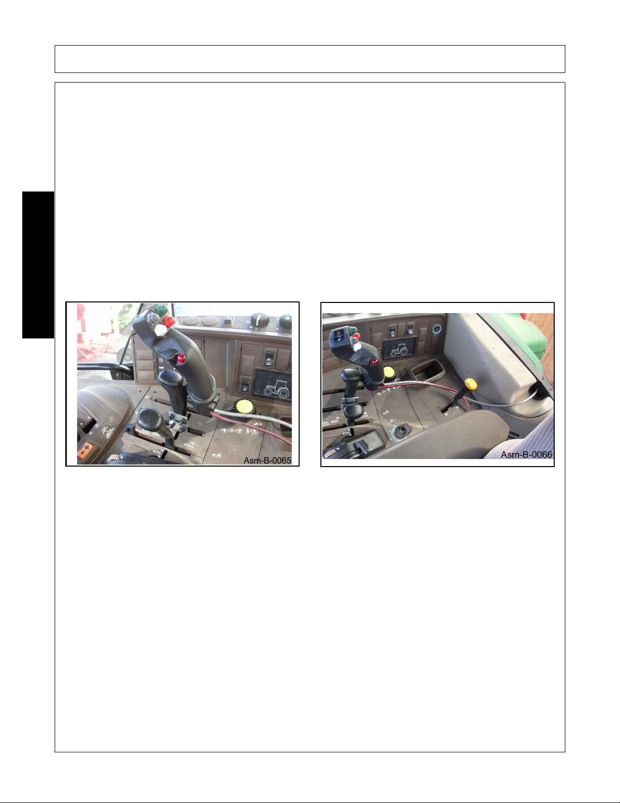
MOUNTING THE REMOTE COMMAND HANDLE
The control handle is normally mounted to an existing tractor remote lever. The control handle selects one
cylinder on the boom to be operated from a remote outlet.
The metal bracket at the base of the control handle is mounted to the remote lever using the U-bolts and
hardware included. Choose either the round U-bolts for round shafts or the flat U-bolts for flat shafts. Two allen
head screws in the mounting bracket are used to keep the handle from rotating on a round shaft and can also
be used to hold the bracket more securely on a flat shaft.
The bracket at the base of the handle can be reversed if needed by removing the allen head screws.
Pull the bracket out of the bottom of the handle, turn it around and replace it in the handle. This allows you to
place the handle in the front of or behind the remote lever providing additional clearance for other controls.
The bracket may be bent, tilting the handle to one side or the other to provide clearance for other controls or to
make the control more comfortable to operate. To reduce the possibility of damaging the handle, the bracket
should be removed from the handle before bending.
ASSEMBLY
After mounting the handle, route the cable away from the handle leaving enough slack in the line to provide
free movement of the control. Secure the cable with the cable ties included.
Unless otherwise specified, all control systems are designed for use on 12 volt, negative ground electrical
systems only. The red and black power wires are to be connected as follows:
Connect the black wire to the frame of the vehicle or to the grounded terminal of the battery.
Connect the red power wire to the source of power, normally this connection is made at the fuse panel. You
must fuse the power wire using the fuse and holder supplied, locate the fuse as close to the source of power as
possible. The power should be controlled by the ignition key to prevent the battery from being drained when
the engine is not running.
Apply decal provided to interior of cab window or other convenient surface.
After the Handle is properly installed the Wiring Harness can be connected to the Valve Harness by connecting
the 9 pin sockets.
Wire harness from valve must run through outside window as shown.
2160 02/10 Assembly Section 3-8
© 2010 Alamo Group Inc.
Page 91

ASSEMBLY
HOSE CONNECTIONS (DIRECT)
(Asm-B-0032)
This hydraulic connection methods requires a break-away valve for the swing cylinder. This valve will be
mounted to the top of a valve mount plate on the Main frame (7) with 2 - 1/4" x 2 3/4" bolts (1) and fasten with
1/4" locknuts (2).Hoses from the tractor ports are then connected to the straight adapters (3). Hoses from the
swing cylinder are connected to the 90 degree elbows (4). The "A" port of the breakaway valve must be
connected to the butt end of the swing cylinder for proper operation of the breakaway feature! A relief hose is
then connected to the other 90 degree elbow (5) which is connected to a straight adapter (6). The other end of
this hose is connected to a filler tube on the tractor hydraulic tank by a special adapter (See Note).The
remaining hoses p/n 02839000 are connected to the bulkhead fittings on the bulkhead plate (7) according to
the decal (Asm-B-0032_A) mounted on the plate. Connect each hose from the tractor to its corresponding
fitting.
NOTE: When connecting the hose from the breakaway valve to the tractor hydraulic filler tube. There are two
types of adapters, depending on the size of the filler tube. A small tube will require a small adapter P/N
00765736. And a large filler tube will use P/N 00765735. To install adapter, insert it into the filler tube, and tap
it lightly until it stops. Screw the elbow into the adapter, and connect the hose from the breakaway valve.
ASSEMBLY
Alternately, for a more reliable connection, this hose can be connected to a "zero back pressure" return port on
the tractor. Consult your tractor's owners manual and/or tractor dealer for information regarding this type of
connection.
2160 02/10 Assembly Section 3-9
© 2010 Alamo Group Inc.
Page 92

ASSEMBLY
HEAD ATTACHMENT
1. Align the boom arm with the mower head lugs. Then insert main pin (1) and lock down with a 3/8 x 2 1/2
bolt (2) and a 3/8 nut. Attach linkage with 2 - 3/4 x 3 bolts (3) and lock with 2 -3/4 nuts (4).
ASSEMBLY
HOSE ATTACHMENT
1. Attach the 1 " hoses, from the articulating arm to the hydraulic motor on the head. Use recommended hose
end torque values in chart on Section 3-5.
2160 02/10 Assembly Section 3-10
© 2010 Alamo Group Inc.
Page 93

ASSEMBLY
HYDRAULIC RELIEF ATTACHMENT (OPTIONAL)
(Asm-B-0037) (Required if attaching to a Non-Quick Hitch Tractor)
1. Remove the top link of the three point from the tractor.
2. Connect the center lug (1) of the Hydraulic Relief Arm (HRA) to the tractor, with the double lugs (2) up,
where the top link was removed.
3. Back the tractor up to the SERVIS 2160 and connect the lower arms (3) of the three point, making sure that
the HRA does not interfere with the SERVIS 2160.
4. Attach the top link of the three point between the SERVIS 2160 and the double lugs (2) on the HRA.
5. Connect the SERVIS 2160 Hydraulics to the tractor so that they are functional.
6. Lift the three point of the tractor so that the SERVIS 2160 is at the desired height.
7. Carefully adjust the SERVIS 2160 hydraulics so that the lower arms (3) of the HRA align with the holes (4)
on the SERVIS 2160.
8. Bolt the HRA arms to the SERVIS 2160.
9. Relieve pressure from the tractor three point.
NOTE: Once the HRA has been completely installed, if the 3-point lift is engaged the HRA stabilizer bars will
be bent.
ASSEMBLY
2160 02/10 Assembly Section 3-11
© 2010 Alamo Group Inc.
Page 94

ASSEMBLY
STARTING UNIT
1. Make sure unit has been properly assembled, all cylinders, Hoses, and the driveline have been connected.
NOTE: Make sure that no materials, tools, or jacks have been left under the mower head. Make sure the
front and rear of the mower are properly guarded to prevent any foreign objects from being thrown by the
mower. All other workers should keep a safe distance from the unit before the mower is started.
2. Run the mower for about 2 - 3 minutes to fill hydraulic lines and hoses with fluid.
3. Check the fluid level at sight gauge (Asm-B-0011). If oil is below sight gauge fill as required to bring to
sight gauge.
4. Remove the filler cap. (Asm-B-0007)
5. Fill the hydraulic reservoir until the fluid is visible through the sight gauge. (Asm-B-0010)
ASSEMBLY
2160 02/10 Assembly Section 3-12
© 2010 Alamo Group Inc.
Page 95

ASSEMBLY
6. Avoid hydraulic contamination by filtering the hydraulic oil while filling the hydraulic tank. Filter buggies or
carts are commercially available for hydraulic system clean-up. These consist of a high-efficiency, highcapacity filter, a circulating pump, a drive motor, and hoses for connecting to the overhauled machine's
hydraulic system. Asm-B-0008 & Asm-B-0009.
ASSEMBLY
7. When adding hydraulic oil, use only new oil from a sealed barrel. Used oil or oil from an open barrel may
contain high levels of contamination. Transfer the oil into the hydraulic tank by using a hydraulic filter pump
unit equipped with a properly operating 10 micron filter. This will insure that the oil being added is clean.
Do not pour the oil directly into the hydraulic tank since most oils (even from a sealed barrel) have contaminants that should be removed, before operating the hydraulic system.
8. Run the mower at PTO operating speed (540 or 1000 RPM) for 20 minutes while checking for any a leaks
and making sure mower is operating correctly.
Change the return filter in tank and suction filters after the first 200 hours of operation.
Change the filters again at 800 hours; then, change the oil and filters at 1600 hours. After
that, continue to change the filter every 800 hours and the oil every 1600 hours. Hydraulic oil
to be 15W 40CD service or equal. Use the above procedures as part of a good filter
maintenance program.
2160 02/10 Assembly Section 3-13
© 2010 Alamo Group Inc.
Page 96

ASSEMBLY
ASSEMBLY
All Servis and Servis-Rhino Boom Mowers mounted on Non-Cab Tractors require without
exception a suitable Operator Protective Cage be installed before operating to prevent
Operator injury by objects thrown by the blades. The Servis Operator Protective Cage may
be ordered with the machine or from the Extra Equipment Section (For your particular
tractor, some modification to this Cage may be necessary.)
A protective cage may be constructed and attached to the tractor and the tractor ROPS (Roll Over Protection
System) only if it conforms to the following:
1. The Right side and top of the operators compartment must be completely protected as shown. In the case
of a tractor with a ROPS mounted hard canopy, only the right side will need to be protected.
2. The grating must be not larger than 1-1/2: by 2-1/4", but not so small as to block vision. The frame should
be made for 1" square tubing, or equivalent.
3. The right side must be completely protected (floor-fender-roof) as shown in FIGURE 20, and extend from
the engine hood to at least 12" behind the back of the operator seat. The roof must be at least 48" above
the seat.
4. No grating on the front or back as it will block vision for driving.
5. Only use clamp type attachment on the ROPS. Do not drill, tap, or weld to the ROPS. You may (provided
that it is strong enough) attach L-brackets to the fender and to the floor board, to secure the rest of the
cage.
Additional protection may be added to Cab tractors by attaching the same grating as above with a 1/8" or more
space between it and the glass.
NOTE: Operator must wear Safety Glasses with Side Shields when operating mower.
2160 02/10 Assembly Section 3-14
© 2010 Alamo Group Inc.
Page 97

ASSEMBLY
Pre-Customer Delivery Check List
1. Is oil level in the tank even with the sight gauge on the tank?
2. Has the proper oil been used in the system?
Proper oil is universal service oil or equal.
3. Does Boom machine movement match operation decal - Swing, Lift, Dipper, and Tilt?
4. Is control valve free and does not stick?
5. Are all hoses tight and do not leak?
6. Are all decals in place? See manual for decal description and placement.
7. Have all grease points been adequately greased?
8. Are all bolts tight?
9. Have all hoses been properly routed so that hoses do not kink or bind when boom
is articulated through all motions?
10. Is machine equipped with proper operator protection? Non-cab tractor must have cage.
11. Is head rotation correct? On rotary heads (looking from the top of the deck) rotation
should be clockwise so that debris will be thrown away from the tractor.
12. Are spindle housing bolts tight? Is spindle assembly tight? Are bolts that hold
blade carrier to spindle tight?
13. Does head operate smoothly at normal operating speed? Head should not
vibrate excessively.
ASSEMBLY
2160 02/10 Assembly Section 3-15
© 2010 Alamo Group Inc.
Page 98

Page 99

OPERATION SECTION
© 2010 Alamo Group Inc.
Operation Section 4-1
Page 100

OPERATION
RHINO 2160 BOOM MOWER
OPERATION INSTRUCTIONS
Rhino 2160 boom mowers are manufactured with quality material by skilled workers. The boom is designed to
attach to a tractor and operate the rotary head to cut grass and weeds. The boom and head are equipped with
protective deflectors and/or chain guards to prevent objects being thrown from the mower by the blades,
however, no shielding is 100% effective. All shields, guards, deflectors, and chains equipped on the unit must
be maintained on the mower in good operational condition.
It is the operator’s responsibility to be knowledgeable of all potential operating hazards and to take every
reasonable precaution to ensure oneself, others, animals, and property are not injured or damaged by the
mower, tractor, or a thrown object. Do not operate the mower if passersby, pets, livestock, or property are
directly in front or to the rear of the unit.
This section of the Operator’s Manual is designed to familiarize, instruct, and educate safe and proper mower
use to the operator. Pictures contained in this section are intended to be used as a visual aid to assist in
explaining the operation of a rotary mower and are not necessarily of a TW168 cutter. Some pictures may
show shields removed for purposes of clarity. NEVER OPERATE this implement without all shields in place
OPERATION
and in good operational condition. The operator must be familiar with the mower and tractor operation and all
associated safety practices before operating the mower and tractor. Proper operation of the mower, as detailed
in this manual, will help ensure years of safe and satisfactory use of the mower.
IMPORTANT: To avoid mower damage, retorque all bolts after the first 10 hours of operation. Retighten blade
carrier retaining nut on gearbox lower shaft to 300 ft. lbs.
READ AND UNDERSTAND THE ENTIRE OPERATING INSTRUCTIONS AND SAFETY SECTION OF THIS
MANUAL AND THE TRACTOR MANUAL BEFORE ATTEMPTING TO USE THE TRACTOR AND
IMPLEMENT. If you do not understand any of the instructions, contact your nearest authorized dealer for a
full explanation. Pay close attention to all safety signs and safety messages contained in this manual and
those affixed to the implement and tractor. OPS-U- 0001
READ, UNDERSTAND, and FOLLOW
death may occur unless care is taken to follow the warnings and instructions stated in the
Safety Messages. Always use good common sense to avoid hazards.
Si no lee ingles, pida ayuda a alguien que si lo lea para que le traduzca las
medidas de seguridad.
the following Safety Messages. Serious injury or
(SG-2)
(SG-3)
2160 02/10 Operation Section 4-2
© 2010 Alamo Group Inc.
 Loading...