

SerVision UVG400 Installation Manual
UVG400
Installation Guide
September
2013

SerVision UVG400 Installation Guide
2
Trademarks & Copyright
Trademarks
All trademarks mentioned in this manual are the sole property of their respective manufacturers.
Copyright
SerVision Ltd., Jerusalem, Israel
www.servision.net • info@servision.net
© 2013 SerVision Ltd. All rights reserved.
Notice
Information in this document is subject to change without notice. SerVision Ltd. assumes no responsibility for any
errors that may appear in this manual. Companies, names and data used in examples herein are fictitious unless
otherwise noted. No part of this document may be copied or reproduced in any form, or by any means, electronic or
mechanical, for any purpose, without the express written permission of SerVision Ltd. SerVision Ltd. makes no
warranties with respect to this documentation and disclaims any implied warranties of merchantability or fitness for
a particular purpose.

SerVision UVG400 Installation Guide
3
Table of Contents
Introduction 4
The UVG400 Package 5
Additional Equipment 6
Installing the UVG400 System 7
Selecting a Location for the Unit 7
Diagram of the Rear Panel 7
Connecting Devices to the UVG400 10
Connecting Cameras 10
Connecting PTZ Controllers 10
Connecting Sensors 11
Connecting a Sensor Directly to the Unit 12
Connecting Sensors Using an ADAM Module 12
Connecting Activators 16
Connecting Sensors and Activators Using an IA Relay Board 16
Connecting Microphones 18
Connecting a Speaker or Headphones 18
Connecting a CCTV Monitor 19
Connecting the Mouse 20
Connecting a Switch 20
Connecting Multiple Monitors 20
Setting Up Network Connections 21
Connecting the UVG400 to an External Network 21
Connecting Devices to the UVG400’s Internal Network 21
Connecting the UVG400 to a Power Source 23

SerVision UVG400 Installation Guide
Introduction 4
Introduction
This guide explains how to set up the hardware components of SerVision’s UVG400 security system. The UVG400
belongs to SerVision’s line of embedded Video Gateway units. These units provide state-of-the-art security
functionality, including live video streaming, video recording and playback, motio n detection, sensor management,
real-time event notification, and device activation. All of these features can be accessed remotely via PC, PDA, or
cellular telephone.
The UVG400 can stream video and other security data to users via cabled Ethernet connection or wirelessly via
WiFi or cellular networks. This versatility makes it ideal for securing locations in which cabled connections are not
available: garages, stables, parking lots, construction areas, etc.
Once the UVG400 has been installed as explained in this guide, it must be configured. Configuration is performed
by connecting to the UVG400 unit using a PC that is on the same network as the unit (or connected to the unit
directly using a LAN cross cable) and opening the unit’s configuration utility in a browser. For additional
information about configuring your UVG400, please refer to the Embedded Video Gateway System Guide.
Client software is used for accessing the UVG400 unit remotely in order to view video and events and control the
system in various ways. SerVision offers client software for PCs and for certain cellular telephone and PDA
models. Full instructions for the use of the client applications are available in separate manuals, which can be
downloaded at http://www.servision.net
.
SerVision UVG400 Installation Guide
The UVG400 Package
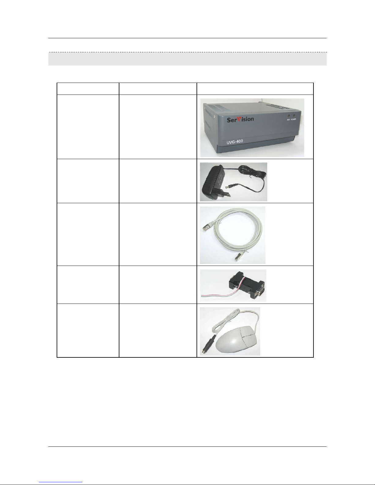
The UVG400 package contains the following items:
Item Description Illustration
UVG400 unit Video Gateway
Power supply cable Connects the unit to an
electrical outlet
Ethernet (LAN) cable Connects the unit to a network
RS232/485 serial
adapter
Connects PTZ controllers to
the unit
Mouse Mouse for use with CCTV
monitors
The UVG400 Package 5
SerVision UVG400 Installation Guide
Additional Equipment 6
Additional Equipment
Up to four video cameras can be connected to the UVG400. You must acquire the cameras you require; they are not
included in the UVG400 package. For information about camera compatibility and about connecting the cameras to
the unit, see Connecting Cameras, page 10, or consult your vendor.
In addition to the cameras, you may wish to incorporate some or all of the optional equipment listed below into your
security system. For additional information about these items and the cables required to connect them, please refer
to the installation instructions for each type of device.
NOTE: This equipment is not included in the UVG400 package.
• Cellular modem with USB adaptor (see Connecting the UVG400 to an External Network, page 21)
Note: Not all cellular modems are supported. Please contact your UVG400 supplier or SerVision technical
support for a list of supported cellular modems.
• USB extension cord for connecting the cellular modem to the unit; the modem functions best if it is installed
as high up as possible and in an exposed location (see Connecting the UVG400 to an External Network,
page 21)
Note: The extension cord should not be longer than about 1.5 meters.
• WiFi card with USB adaptor (see Connecting the UVG400 to an External Network, page 21)
Note: Not all WiFi cards are supported. Please contact your UVG400 supplier or SerVision technical support
for a list of supported WiFi cards.
• Up to four dry-contact sensors (see Connecting Sensors, page 11)
Note: Up to four dry-contact sensors can be connected directly to the UVG400 unit. If you use either an
ADAM module or an IA relay board, as described below, you can connect an additional 16 dry-contact
sensors via the unit’s RS232/485 connector.
• ADAM Data Acquisition Module and ADAM isolated RS232->RS422/RS485 converter, for connecting up to
16 dry-contact sensors (see Con necti n g Sensors, page 11)
• Intelligent Appliance IA-3126-2 relay board, for connecting up to 16 dry-contact sensors (see Connecting
Sensors and Activators Using an IA Relay Board, page 16) and 16 activators to the UVG400 unit
• Up to two dry-contact activators (alarms or other devices that are turned on or off in response to the activation
of a sensor; see Connecting Acti v at ors, page 16)
Note: Up to two activators can be connected directly to the UVG400 unit. If you use an IA relay board, as
described above, you can connect an additional 16 activators via the unit’s RS232/485 connector.
• Up to two microphones (see Connecting Microphones, page 18)
• Speaker or headphones (the unit already contains a built-in speaker; see Connecting a Speaker or Headphones,
page 18)
• CCTV monitor for closed-circuit video display (see Connecting a CCTV Monitor, page 19)
• Push-button switch to change the display in a connected CCTV monitor (see Connecting a Switch, page 20)
• Toggle (on-off) switch to change the active outline (see Connecting Sensors, page 11)

SerVision UVG400 Installation Guide
Installing the UVG400 System 7
Installing the UVG400 System
These are the steps that you will typically follow in order to install the UVG400 system:
1. Place the UVG400 unit in its desired location; see Selecting a Location for the Unit, page 7.
2. Install the video cameras in their desired locations.
3. Install the sensors in their desired locations (optional).
Note: Four sensors can be connected directly to the unit; another 16 must be connected through an ADAM
module or an IA relay board; see Connecting Sensors, page 11.
4. Install a toggle switch to change the active outline (optional); see Connecting Sensors, page 11.
5. Install the activators in their desired locations (optional).
Note: Two activators can be connected directly to the unit; another 16 can be connected through an IA relay
board; see Connecting Activators, page 16.
6. Install a CCTV monitor in its desired location (optional).
Note: If you want to use a mouse to control the monitor display, place the monitor close to the UVG400 unit,
because the mouse is plugged into the unit, not into the monitor.
7. Install a push-button switch in its desired location (optional); the push-button switch can be used to change the
display on the CCTV monitor, if a monitor is connected to the unit; see Connecting Sensors, page 11.
8. Connect the cameras and other devices to the UVG400 and to a power supply, as required; see Connecting
Devices to the UVG400, page 10.
9. Place the cellular modem in an appropriate location in the vehicle and connect it to the unit using a USB
extension cord (optional); see Connecting the UVG400 to an External Network, page 21.
10. Connect the WiFi adaptor to the unit (optional); see Connecting the UVG400 to an External Network, page 21.
11. Connect the unit to a LAN using an Ethernet cable (optional); see Connecting the UVG400 to an External
Network, page 21.
12. Install any devices that will be connected to the UVG400's internal network in their desired locations. Connect
them to a power source and to the unit (optional); see Connecting Devices to the UVG400’s Internal Network,
page 21.
13. Connect the UVG400 unit to a power source; see Connecting the UVG400 to a Power Source, page 23.
Selecting a Location for the Unit
The UVG400 unit should be placed on a flat surface such as a table or shelf. (It is not designed for mounting
directly on a wall.) Ensure the unit has at least a few centimeters (1–2 inches) of space above it and on all sides for
ventilation.
When choosing a location for the UVG400, bear in mind that the unit must be connected to a power outlet and a
LAN or a PC, and that other devices (cameras, sensors, etc.) must be connected to it. Choose a location in which
these connections are feasible.
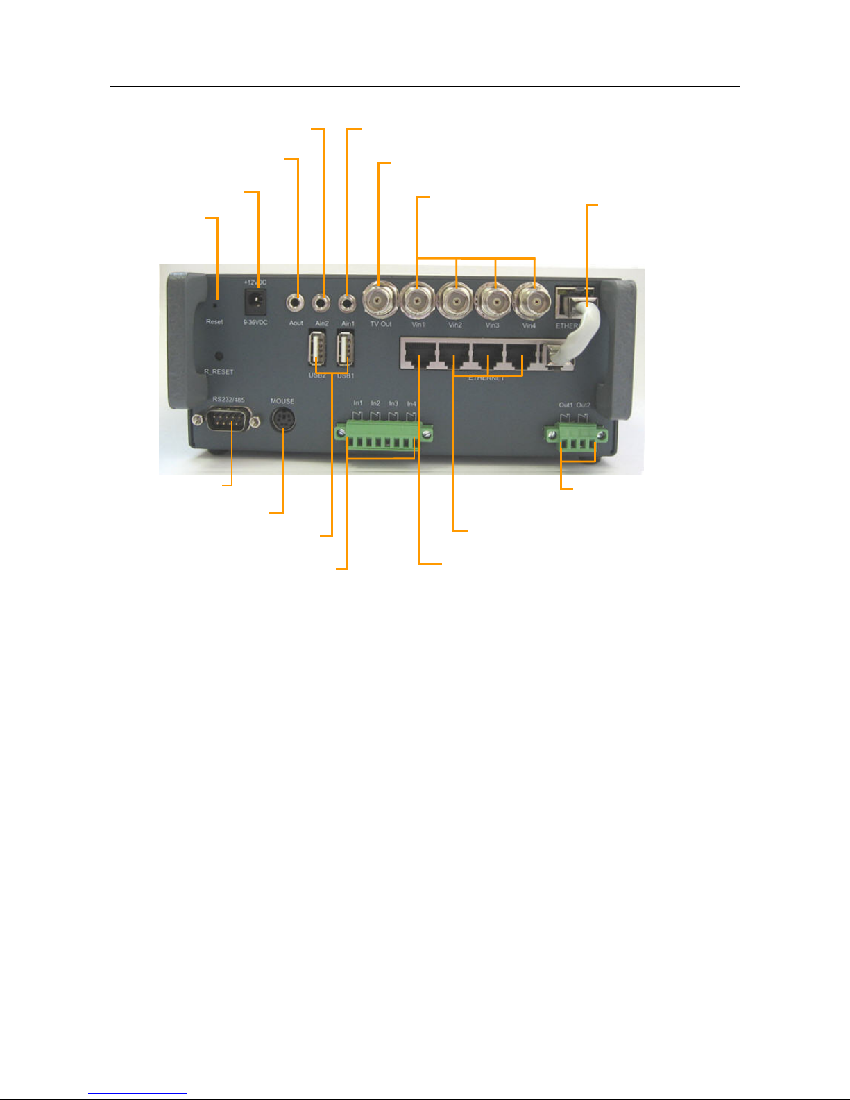
Diagram of the Rear Panel
The rear of the UVG400 unit contains the connectors and controls described below.
SerVision UVG400 Installation Guide
Reset
Powe
r
A
udio Out (Aout)
A
udio In2 (Ain2)
A
udio In1 (Ain1)
T
V Out
Ethernet
Cable
V
ideo In
V
in1–Vin4
Installing the UVG400 System 8
Figure 1: UVG400 connectors and controls
RS232/485
USB Ports
Mouse Connecto
r
Sensors
In1–In4
Activators
Out1, Out2
Ethernet In
Ethernet Out
 Loading...