

Page 1
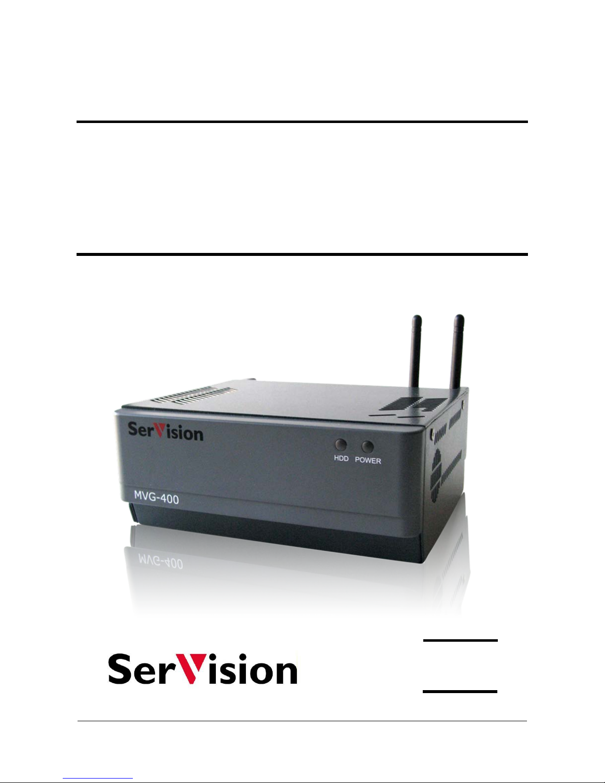
MVG400
Installation Guide
September
2013
Page 2

SerVision MVG400 Installation Guide
1
Trademark s & Cop y righ t
Trademarks
All trad emark s ment ioned in this manual are the sole property of their resp ective manufacturers.
Copyright
SerVision Ltd., Jer usalem, Israel
www.servision.net • [email protected]
© 2013 SerVi sion Lt d. All rig ht s reserved.
Notice
Information in this document is subject to change without notice. SerVision Ltd. assumes no responsibility for any
errors that may appear in this manual. Compani es , na mes and data u s ed in exa mples herein are fict itious un less
oth e rwis e noted . No part of this docum ent may be copied or reprodu ce d in any form, or by any means, electronic or
mechanical, for any purpose, without the express written permission of SerVision Ltd. SerVision Ltd. makes no
warranties with respect to this documentation and disclaims any implied warranties of merchantability or fitness for
a particular purpose.
Page 3

SerVision MVG400 Installation Guide
2
Table of Contents
Introduction 3
The MVG400 Package 4
Additional Equipment 6
Installing the MVG400 System 7
Selecting a Location for the Unit 8
Preventing Overheating 8
Installing the Unit 10
Diagram of th e Re a r Pan e l 11
Supplying Power to Devices Con ne cted to the Uni t 12
Turning the Device Power On and Off with the Ignition 12
Transforming the Supplied Voltage to 12V 13
Configuring the Power-Supply Activator 14
Conn ecti n g D ev i c es to th e MVG400 15
Connecting Cameras 15
Connecting PTZ Controllers 15
Connecting Sensors 17
Connecting a Sensor Directly to the Unit 17
Connecting Sensors Using an ADAM Modu le 18
Connecting Activators 21
Connecting Senso rs and Ac tivat o rs Usin g an IA Relay Board 22
Connecting Microphones 23
Connecting a Speaker or Headphones 24
Connecting a CCTV Monitor 24
Connec ting a Switch 26
Connecting Multiple Monitors 26
Setting Up Network Connections 27
Connecting the MVG400 to an External Network 27
Connecting Devices to the MVG400’s Internal Network 27
Connecting the GPS Antenna 29
Connecting the MVG400 to a Power Source 30
Connecting the Wire Connector to the Unit 30
Connecting the Unit to an Electrical Outlet 31
Connecting the Unit to the Vehicle Battery 32
Appendix 1: Removing the Unit’s Hard Drive 36
Appendix 2 : Using the 12VDC Po wer Out Connector 38
Page 4

SerVision MVG400 Installation Guide
Introduction 3
Introduction
This guide explains how to set up the hardware components of SerVision’s MVG400 security system. The
MVG400 bel ongs to SerVision’s line of embedded Video Gateway units. These uni ts provide state-of-the-art
security functionality, including live video streaming, video recording and playback, motion detection, sensor
management, real-time eve nt notification, an d devi ce a ctivat ion. All of these features can be a ccess ed remotely via
PC, PDA, or cellu lar telephone.
The MVG400 is optimized for deployment in vehicles. I t h as built-in support for cable-based, Wi F i, and cellu lar
networking, and contains an in ternal G PS r eceiver tha t makes it possi bl e to track th e locati on an d rou te of the
vehicle in which it is installed. It can also be in tegrated wi th some fl e et-management systems (such as the Galooli
system; see http://www.galooli.com/solutions/galooli-fleet/
).
Once the MVG400 has been in stalled a s exp lained in th is guide, it mu s t be con figur ed . Configuration is performed
by connecting to the MVG400 unit using a PC that is on the same network as the unit (or connected to the unit
directly using a LAN cross cable) and opening the unit’s configuration utility in a browser. For additional
informa tion about confi guring your MVG400, please refer to the Embedded Video Gateway System Guide.
Client software is used for accessi ng the MVG400 unit remotely in order to view video and events and control the
system in various ways. SerVision offers client software for PCs and for certa in cellular t elephon e an d PD A
models. Full instructions for th e u s e of th e client a pp li cations are availa bl e in s ep arate manuals, whi ch can be
downloaded at http://www.servision.net
.
Page 5
SerVision MVG400 Installation Guide
The MVG400 Package 4
The MVG400 Package
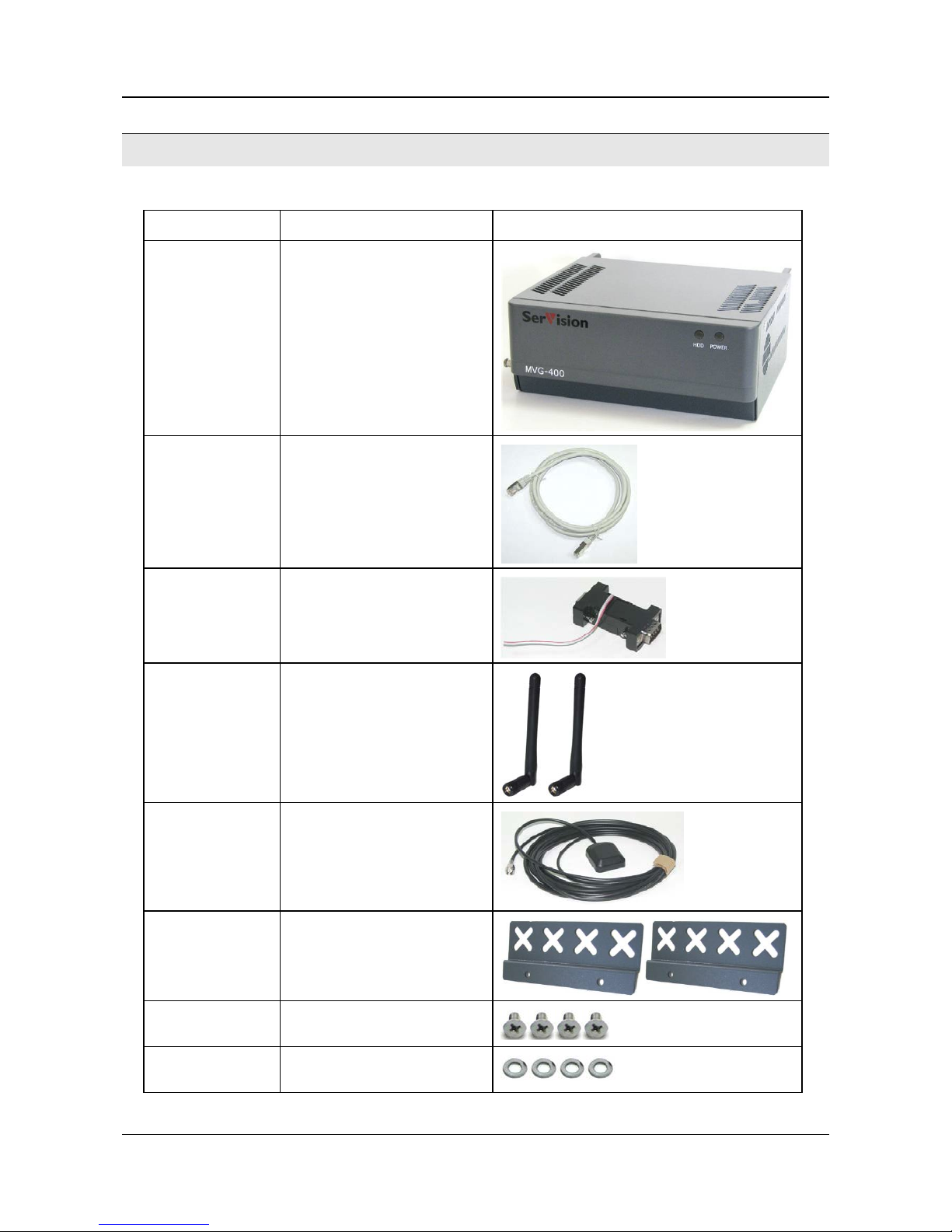
The MVG400 p ackage con tains the fol lowing items:
Item Description Illustration
MVG400 unit Video Gateway
Etherne t (L AN )
cable
Connects the unit to a PC (or a
cable-based local network)
RS232/ 485 serial
adapter
Connec ts PT Z con tr ol lers to the
unit
2 WiFi antennas
Enable the built-in WiFi adapter
to conne ct to WiFi access points
GPS antenna
Enables the built-in GPS receiver
to conne ct to satellites
2 supports
Used to install the unit in the
vehicle
4 screws
Used to connect the supports to
the unit
4 washers
Used to connect the supports to
the unit
Page 6
SerVision MVG400 Installation Guide
The MVG400 Package 5
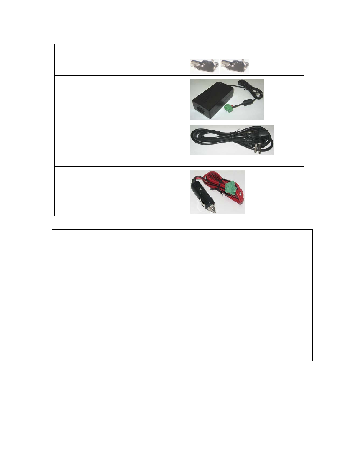
Item Description Illustration
2 keys
Used to open or lock the hard drive compartmen t
Power-supply cable
Connects the power-supply to the
unit
Note: For large orders, only a
small number of power-supply
cables are normally supplie d (see
note
below).
Power-connector
cable
Connects the power-supply to an
electri c out le t
Note: For large orders, only a
small number of power-connector
cables are normally supplie d (see
note
below).
Power cord
Connects the unit to the vehicle
battery via th e ci g a ret te lig h te r
Note: Normally supplied only
with demo units (see note
below).
NOTE: The power-s u p p ly cable, the power-con nector cable, and th e po wer cord with cigarette-lighter
connector are not required for operation of the MVG400 in a vehicle, beca u s e the unit is hard-wired to
the vehicle batt ery when it i s installed .
Typically, the MVG400 unit is configured in an office setting before it is installed, and for that the
power-supply and power-connector cables are used. Sin ce on l y a small number of unit s ar e configur ed
at one ti me, power-supply and power-connector cables are not required for every unit of a large order .
After configuration, the units normally only need power-supply and power-connect or cables if they
malfunction and are removed from the vehicles in which they are installed in order to perform troubleshooting pr oc edures on t hem in the office.
The power cord, which has a cigarette-lighter connector, is not required for normal installations; it is
useful primarily for test ing of demo units, which are not installed in the vehicl es or hardwired to the
battery.
In keeping with Ser V ision’s “green” p ol icy of preventing unnecessary waste, on ly a limited number of
power-supply and power-connector cables are supplied wi th each order. Plea s e r etain the cables you
receive for use with all of the unit s you p urchase. Similar ly, power cords with cigarette-lighter
connectors are on ly suppli ed wi th demo unit s . If you require more of an y of these it ems than are
normally suppl ied, plea se consult yours sales representati ve.
Page 7
SerVision MVG400 Installation Guide
Additional Equipment 6
Additional Equipment
Up to four vi d eo ca meras can be con nected t o th e MVG400. You must acquire the cameras you require; they are not
included in the MVG400 package. For information about camera compatibility and about conn e c tin g the cameras to
the unit, see Connecting Cameras, page 15, or con s ult your vendor.
In addition to the cameras, you may wish to incorporate some or all of the optional equipment listed below into your
security system. For additional information about th es e items and the cables r equired t o connect them, please r efer
to the installation instructions for each t ype of d evice.
NOTE: This equipment is no t included in the MVG400 package.
• Cellular modem with USB adapter (see Connecting the MVG400 to an External Netw ork, page 27)
Note: Not a ll cellul ar modems are supported. Pleas e contact your MVG400 supplier or SerVision technical
support for a list of supported cellular modems.
• USB extension cord for connecting the cellular modem to the unit; the modem functions best if it is installed
high in the vehicle in an exposed location (see Connecting the MVG400 to an External Network, page 27)
Note: The extension cord should not be longe r than about 1. 5 meters.
• Up t o four dry-contact sensors (see Connecting Sensors, page 17)
Note: Up to four dry-cont act sensors can be connected directly to the MVG400 unit. If you use either an
ADAM module or an IA relay board, as described below, you can connect an additional 16 dry-contact
sensors via the unit’s RS232/485 connector.
Note: If you connec t a touc hscreen monitor to t he MVG400, you cannot also connect an AD A M m odul e or an
IA relay board. In this case, you can only connect up to four dry-contact sensors to the unit.
• ADAM Data Acquisiti on Module and ADAM isolated RS232->RS422/RS485 converter, for connecting up to
16 dry-contact sensors (see Connecting Sensors, page 17)
• Intelligent App liance IA-3126-2 relay board, for connecti ng up to 16 dry-contact sensors (see Connecting
Sensors and Activators Using an IA Relay Board, page 22) and 16 acti vators to the MVG400 unit
• Up t o two dry-conta ct activat ors (alarm s or other devices that are turned on or off i n respon s e t o the activat ion
of a sen sor ; see Connecting Activators, page 21)
Note: Up to two activat ors can be connected d irectl y to th e MVG400 unit. If you use an IA relay board, as
described above, you can connect an add itional 16 a c t ivators via th e unit’ s RS232/485 connector.
Note: If you connec t a touc hscreen monitor to t he MVG400, you cannot also connect an IA r e lay board. In
this case, you can only connec t up to t wo dry-contact activators to the unit.
• Up to t wo mi crophone s (see Connecting Microphones, page 23)
• Speaker or headphones (th e un it already contains a built -in speaker ; see Connecting a Speaker or Headphones,
page 24)
• CCTV monitor for closed-circuit video display (see Connecting a CCTV Monitor, page 24)
• Push-button switch to change the display in a connected CCTV monitor (see Connecting a Switch, page 26)
• Toggle (on-off) switch to change the active out line (see Connecting Sensors, page 17)
• Insul ated plastic container with two built-in fans in which the MVG400 unit can be placed (s ee Preventing
Overheating, page 8)
• Additional hard drives (see Appendix 1: Removing the Unit’s Hard Drive, pa ge
36)
Page 8

SerVision MVG400 Installation Guide
Installing the MVG400 System 7
Installing the MVG400 System
These are the steps that you will typically follow in order to install the MVG400 system:
1. Install the MVG400 unit in it s d es ired location using the supplied supports; see Selecting a Location for the
Unit, page 8.
Note: If you are inst alling the MVG400 in an in sul ated container (see Preventing Overheating, page 8), you
must install the container in th e veh icle and the MVG400 in th e con tain er.
2. Install the video cam er as in their d es ired loca tions.
3. Install the sensors in their desired locations (optional).
Note: Four sensors can be connected dir ectly to th e un it; another 1 6 can be conn ected thr ou gh an ADAM
module or an IA relay board; see Connecting Sensors, page 17.
4. Install a toggle switch in its desired location (optional); the toggle-button switch can be used to change the
active outlin e; see Connecting Sensors, page 17.
5. Install the activators in their desired locations (optional).
Note: Two activators can be connected directly to the unit; another 16 can be connect ed th rough an IA relay
board; see Connecting Activators, page 21.
6. Install a CCTV monitor in its desired location (optional).
7. Install a push-button switch in its desired location (optional); the push-button switch can be u sed to change the
display on the CCTV monitor, if a monitor is connected t o the un it; see Connecting Sensors, page 17.
8. Connect the cameras and other d evi ces to the MVG400, as required; see Connecting Devices to the MVG400,
page 15.
9. Connect the cameras and other d evi ces to the vehicle battery, as required ; see Supplying Power to Devices
Connected to the Unit, page 12.
10. Place the cellul ar modem in an appropriat e locati on in the vehicl e and connect it to the unit using a USB
extension cord (optional); see Connecting the MVG400 to an External Network, page 27.
11. Connect the WiFi antennas to the uni t ; see Connecting the MVG400 to an External Network, page 27.
12. Connect the unit to a LAN using an Ethernet cable ( optional); see Connecting the MVG400 to an External
Network, page 27.
13. Install the GPS an tenna in an a ppr op r iate loca tion in the vehicle an d con nect it to th e unit (optional); see
Connecting the GPS Antenna, page 29.
14. Install any devices that will be connected to th e MVG400's internal network in their desired locations. Connect
them to a power source and to the unit (optional); see Connecting Devices to the MVG400’s Internal Network,
page 27.
15. Connect the MVG400 unit to a power source; see
Connecting the MVG400 to a Pow er Source, page 30.
NOTE: The unit, the devices connect ed to it, an d the cables used t o connect them, must all be securely fasten ed
to the veh icle to ens ure they do not becom e d etach ed from their locations when the vehicle is in
motion.
Page 9

SerVision MVG400 Installation Guide
Installing the MVG400 System 8
NOTE: Installing the unit and its peripheral equipment in a vehicle is a complex process. It is highly
recomm ended tha t it be p erformed b y a trained s p ecialist in vehicle in s tallati ons.
Selecting a Locati o n for the U ni t
The unit should be installed in a cool and vent ilated l oca tion, pr ot ected from d irect sunlight and water (including
liqui d s u s ed to cl ean the in si d e of the vehicle), and as far away from humidity as possible. It should not be installed
in a closed location, such as the in the trunk or dashboard, or under the paneling, of a car. Ensure the unit has at
least 20 centimeters (eight inches) of spa ce above it and on all sides for ventilation. It can be in st alled either
hori zontally or vertic ally.
When choosing a location for the MVG400, bear in mind that th e un it must be connected t o th e vehicle ba ttery and
ignit ion (if req uired), that other devices (cam eras, sen s ors, PC, et c.) must be connected both to it and to power
sources, and tha t the GPS anten n a an d cellular modem mu st be lo cated relatively high up an d in ex posed locations
(see Connecting the MVG400 to an External Network, page 27; Connecting the GPS Antenna, pag e 29). Choose a
location in whi ch th es e connect ions are feasi ble.
Preventing Ove r heating
MVG400 units should be in s t alled in the pa s s e nger comp artment in a locati on th at is cooled by the vehicle's air conditioning when the air conditioner is on. Ideally, the units should be installed in insulated plastic containers with
built-in fans. E ach conta i ner should have two fans, one to draw co ol air into the container and the other to push hot
air out of it. Containers of this type are available for purchase from vehicle-accessory suppliers. The containers
should be installed in the vehicles in accessible locations, with as much ventilation as possib le . Ce llular modems,
and the ends of GPS an t enn as, shoul d be placed outside the con tainers. (Cell ul ar mod ems should be connected to
MVG400 units using USB extension cords; see Connecting the MVG400 to an External Network, page 27.) If you
plan to remove the hard-drive from the unit without removing the unit from the container, make sure to allow
enough space to open the hard-drive compartment (see Appendix 1: Removing the Unit’s Hard Drive, page 36).
NOTE: Do not inst all the unit in a metal con tainer; metal interferes with wireless reception.
Figure 1: Video Gateway installed in an insulated plastic container with two fans
Fan
Fan
Page 10

SerVision MVG400 Installation Guide
Installing the MVG400 System 9
Figure 2: Video Gateway installed in an insulated container attached to the back of a seat in a car
In buses and trains, the MVG400 can be installed in an air-conditioning duct or in the compartment above the
driver's seat.
Figure 3: Video Gateway installed in the air-cond itioning duct of a bus
Figure 4: Video Gateway installed in the compartment above the driver's seat in a bus
Page 11
SerVision MVG400 Installation Guide
Installing the MVG400 System 10
Installing the Unit
The unit should be fir mly secured to ensur e it d oes not move around when the vehicle is in motion; if the unit is
dislodged from its location in the vehicle, it may be damaged, hit people in the vehicle, or harm other items with
which it comes int o contact.
NOTE: To install th e uni t, you will n eed s crews to secu re th e unit to its anchoring s urface (not s u p pl ied; see
step 2 below).
To install the MVG400:
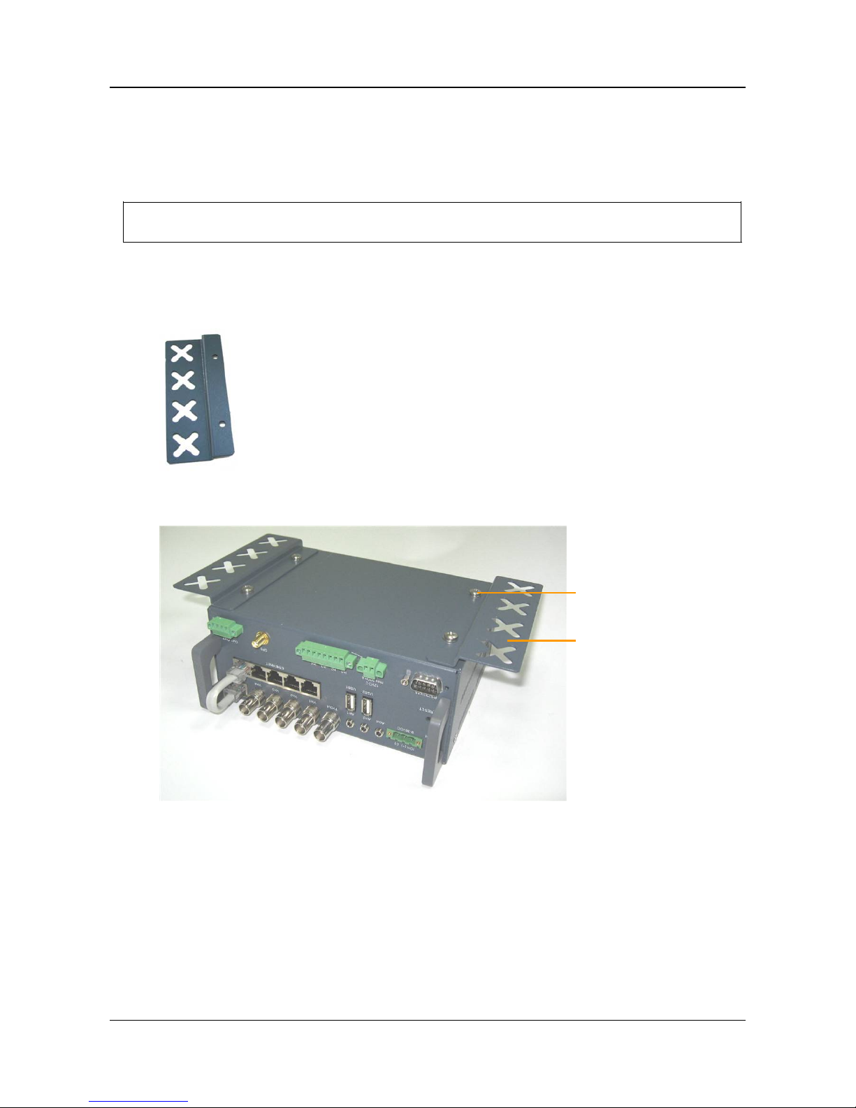
1. Connect the two side supports to either side of the bottom of the MVG400, using two screws and two washers
for each support. (The screws and washers are supplied with the MVG400.)
Figure 5: Side support
Figure 6: S u pports attached to b ottom of the MVG400
Side support
Screw and washer
Page 12

SerVision MVG400 Installation Guide
Installing the MVG400 System 11
2. Place the unit in the desired loca tion and attach it securely by conn ecting th e s i de supports to the anchor ing
surfa ce with two or th ree screws on each sid e. (These screw s are not included with th e MVG400.)
Note: Th e unit can be pla ced horizontally or verticall y. I f i t is placed ver ticall y, the left sid e (the side
contain i ng the har d drive) sh ould fa ce up.
Figure 7: Hard-drive compartment
Diagram of the Rear Panel
The rear of t he MVG400 unit contain s the connect ors described b elow.
Figure 8: MVG400 connectors
Power
Audio Out (Aout)
Audio In2 (Ain2)
Audio In1 (Ain1)
TV Out
Ethernet
Cable
Video In
Vin1–Vin4
RS232/485
USB Port
12VDC Power Out
Sensors
In1–In4
Activators
Out1, Out2
GPS Antenna
Ethernet
In
Ethernet
Out
WiFi
Antennas
Hard-drive compartment
Page 13
SerVision MVG400 Installation Guide
Installing the MVG400 System 12
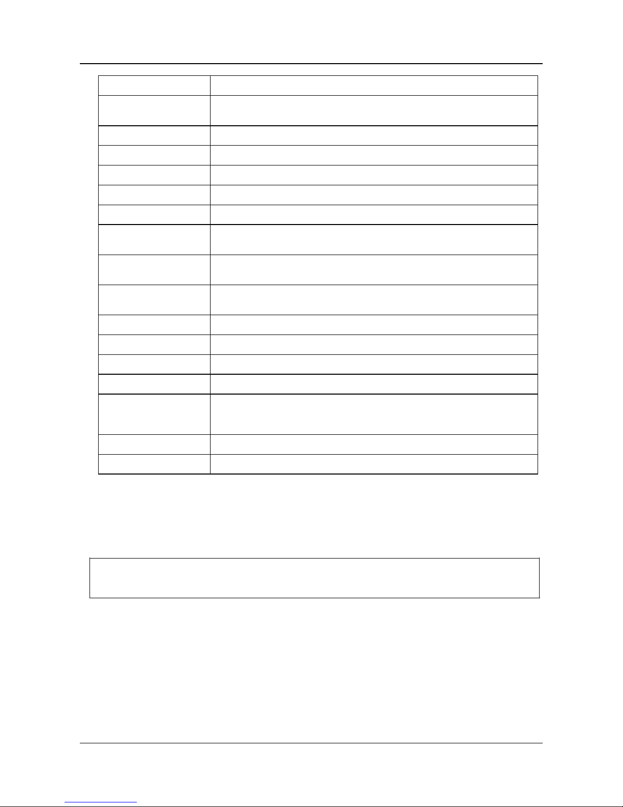
Connector Description
Power
Connec to r for the p ower suppl y and, if requ ir ed , for th e ignition connecti on (s ee
page 30)
Audio Out (Aout) Connector for an external speaker or headphones (see page 24)
Audio In2 (Ain2) Connector for an active microph one (see page 23)
Audio In1 (Ain1) Connector for a passive micropho ne (se e page 23)
TV Out Connector for a CCTV monitor (see pag e 24)
Video In (Vin1–Vin4) Connectors for video cameras (see page 15)
Etherne t Cable
Cable connecting the Video Gateway component of the MVG400 to the unit’s
router. D o n ot disconnect.
Etherne t Ou t
10/100 Base-T LAN connector for connecting the unit to an external network (LAN
or WAN; see page 27.)
Ethernet In
Three 10/ 10 0 Ba se -T LAN connectors for connecting other devices to the internal
network managed by the MVG400’s router (see page 27)
Activators (Ou t1 , Out 2) Activator connectors (see page 21)
GPS Antenna GPS antenna connector (see page 29)
Sensors (In1 – In4) Sensor connectors (see p age 17)
12VDC Power Out Supplies power to external devices such as sensors (see page 38)
RS232/485
Serial (COM) port for PTZ controllers (see page 15), ADAM modules (see page 18),
a touch-screen controlle r (see page 24), a device to receive GPS location data (for
additional information, consult your vendor), or technicians' use
WiFi antennas WiFi antenna connectors (see page 27)
USB Port Connector for a cellu lar mod e ms wit h a USB adapter (see page 27)
Supplying Power to Devices Connected to the Unit
Cameras and most other peripherals connected to the MVG400 unit usually require independent power supplies.
These devices should be connected d irectl y to the vehicl e ba ttery (or som e other power source) .
NOTE: In som e cases, it may be possible to provide power to certain devices through the 12VDC Power Out
connector on the rear panel of the MVG400. Thi s op tion is not a ppropria te for supplyin g power to
cameras. For additional information, se e Using the 12VDC Power Out Connector, page 38.
Turning the Device Power On and Off with the Ignition
Normally, the MVG400 is config ured to shut down whene ver the vehicle igni t ion i s turned off. If you want
peri pheral devices that are connected to the uni t to shut down wh en the vehi cle ignition is off, you sh ou ld route their
power su p p lies thr ough one of th e act ivator connectors (Out1 or Out2) on the MVG400 unit, as illustrated below.
Page 14

SerVision MVG400 Installation Guide
Installing the MVG400 System 13
Figure 9: Connecting cameras to the power supply through an Activator connector
NOTE: Devices that draw their power through the 12VDC Power Out connector on the MVG400 (see
Using
the 12VDC Power Out Connector, page 38) are alway s turned off w hen the MVG400 shuts down .
Transforming the Supplied V olta ge to 12V
When the p ower supply for one or more devices is r ou t ed from the vehicle ba ttery, you must ensure that the voltage
reach in g the devices is 1 2 V . If the vehicle battery supplies power at a voltage other than 12V, you must insert a
transformer between the battery and the device, as in figure 10 below.
In order to ensure that the transformer is compatible with the vehicle battery, it is recommended that it be purchased
in the country in which it will be used. In addition, make sure the capacity of the transformer is more than sufficient
for all of the devices connected to it. You can cal culate the r equ ired capa city by calculatin g the sum of the power
consumptions of each device drawing power from th e ba ttery through th e line. For exa mp le, if four cameras an d
two sensors are connected directly to th e batt er y, and each one uses 2W, the total requiremen t is 12W. Allow an
additional margin of 20-30% when you select the transform er. Thus, if the d evi ces require a total of 12W, get a
transformer that supplies at least 14.4W.
NOTE: You can convert Am ps to Wa t ts using the following formula:
Volts * Amps = Watts
For example, a 12V device tha t operates at 250 mA cons um es 3 Watts: 12 * 0.25 = 3.
Page 15

SerVision MVG400 Installation Guide
Installing the MVG400 System 14
Figure 10: Placing a transformer betw een the vehi cle battery a n d t he de vices drawing power from it
Configuri ng the Power-Supply Ac tiv ator
When the power supply to devices is routed through an activator connector, as described above, the activator must
be config u red correctly in the MVG400's configuration: the Normal Status of the activator must be set to Closed,
as in the illustr ation belo w. (For additional information about configuring the activator, please refer to the
Embedded Video Gateway System G uide, under Configuring Sensor and Ac ti vator Settings.)
Figure 11: Normal Status of activator set to Closed
Normal Status
Page 16

SerVision MVG400 Installation Guide
Connecting Devices to the MVG 40 0 15
Connecting Devices to the MVG400
This sect ion explains how to connect cam er as, sen sors, acti va tors, microphones, a speaker or headphones, a nd a
CCTV mon itor to the MVG400 unit.
NOTE: Make sure that all installed devices are designed to function properly under mobile conditions
(temperature range, vibrations, power su p p ly, etc), th at they are al l install ed in accordance with th eir
manu fa cturer's requir ements, an d that the devices and all cables ar e properly installed an d firmly
fasten ed so that th ey will not becom e d islodged when the vehicle moves. I t is highly recommended to
consul t vehicle ex p erts befor e instal ling external devices.
Connecting Cam er as
Up to four cam eras can be con nected to the MVG400. If the cameras have PTZ contr ols for rem ot e aiming and
zooming, and t he PTZ protoc ols they use are s upported , t he con t rol c ables c an al so be con nected t o t he uni t.
Any PAL or NTSC video cam era with a comp osite video output can be connected to the unit. A cable with a
composite video conne c tor on one end, an d a male BNC connect or on the other , should be used to connect each
camera to the MVG400.
To connect a camera:
1. Install the camera in its desired location.
2. Connect the output of the camera to on e of the Video In connectors on th e r ear panel of the unit.
3. Connect th e camera's power c onne ctor to a power source, as explained under Supplying Power to Devices
Connected to the Unit, page 12.
Connecting PTZ Controllers
If a ca mera has r emote PTZ contr ol features (pan, til t , zoom, and /or focu s), and us e s a s upported PTZ pr otocol, you
can conn ect the control cabl e to the unit. Both RS2 32 and RS48 5 PTZ connect ion types are supported. Consult the
camera documentation for information about which connection type to use.
NOTE: If you are connecting sensors to the unit using an ADAM module, or yo u are using the RS232/485
connector to conn ect a touchscreen CC TV monitor to the unit, you ca n not connect any RS232 PTZ
controllers. For addition al information, se e Connecting Sensors Using an ADAM Module, page 18;
Connecting a CCTV Monitor, page 24.
NOTE:
A cable with a male RCA con nector can be connect ed to a female BNC con nector b y usi n g an
RCA-to-BNC ada ptor.
Figure 12: RCA-to-BNC adaptor
Page 17
SerVision MVG400 Installation Guide
Connecting Devices to the MVG 400 16
If you wan t to connect the PTZ controller s of mu ltiple cam er as to th e unit, only one of the contr ol lers can us e an
RS232 connector – the others must all use RS485 connectors. PTZ controllers for more than one RS232 camera
cann ot be con nected to the unit s imultaneous ly.
If you connect mult iple RS485 PTZ camera con trollers, they shou ld be daisy-chained to the RS232/485 connector,
as described belo w. In this case, each camera in th e cha in must be given a di fferent ID number. Please refer to your
cam era's documen tation for i nfor m ation about con figu ring i ts ID n umber . In addition, n ote that you can only create
an RS485 daisy chain if every link on th e ch ain (i.e. , every cam er a) uses th e same PTZ protocol . Attempting to
connect camera s th at use different prot oc ol s will prevent all of t he cameras from working properly.
To connect an RS232 PTZ controller:
The RS 232 c ontroll er c able s hould end with a female 9 -pin RS232 connector.
• If you are only conne ctin g t he RS232 PTZ controller to the un it, and ar e not connect ing any RS485 PTZ
controllers, plug th e 9-pin RS232 connector directly into the RS232/485 connector on the rear p anel of the
unit.
• If you are also conne ctin g one or m ore RS4 85 PTZ controllers to t he un it, plug th e 9-pin RS232 connector into
the RS232/485 adapter supplied with the unit.
To connect an RS485 PTZ controller:
Each RS485 controller cable should end with two wires.
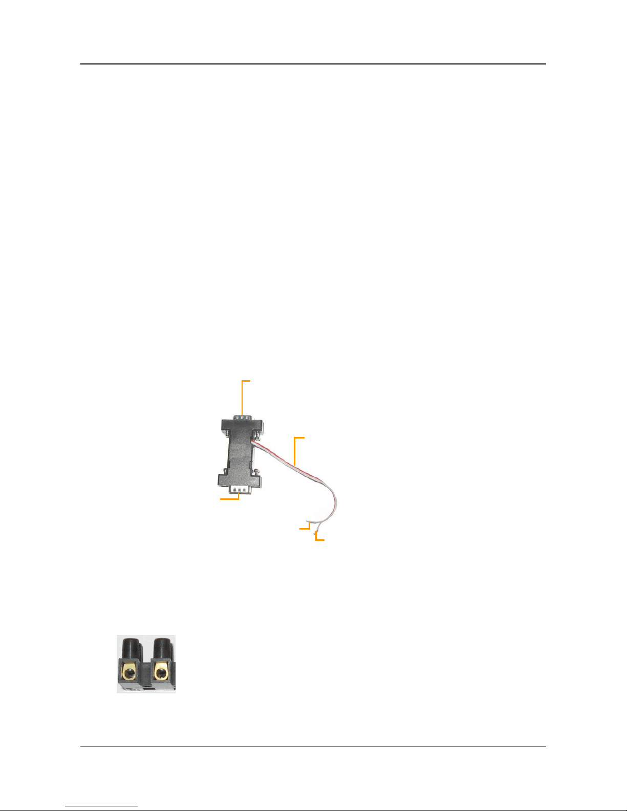
1. Use a wire connector to connect the wires to the RS4 85 connection wires of the ada pter. Be sur e to match th e
positi ve ( +) wire of the controller cabl e to the posit ive (+ red) wire of the adapter, an d the negati ve (-) wire of
the controller cable to th e n eg ative (- gr ey) wire of the ad apter (see fi gure 13).
Figure 13: RS232/485 adapter
To connect multiple RS485 controllers to the adapter, insert the positive (+) wires of all of the controllers into
one slot in the wire connector, an d the negative ( -) wires of all of the controllers into the other slot of the wire
connector.
Figure 14: Wire connector
RS485 connection wires
Plug into RS232/485
connector on MVG400
RS232 connector
Positive (+) wire for RS485
connector (red)
Negative (-) wire for
RS485 connector (grey)
Page 18
SerVision MVG400 Installation Guide
Connecting Devices to the MVG 40 0 17
2. If multiple PTZ camera s ar e con nected to the unit, configur e each camera t o u s e a di fferent ID. For
information about how to do this, refer to the camera documenta tion.
3. Connect the RS232/485 adapter to the RS232/485 connector on the rear panel of the unit.
Connecting Sensors
Sensors are devices that det ect events su ch as a door bein g opened, brakes being pressed, or high G-force pressur e.
Up to f our dry-contact inpu t sensors can be connect ed d irectly to the unit. In addition, if you wish, you can connect
either an ADAM Data Acquisition Module or an IA-3126-2 relay board to the unit. Either of thes e d evi ces makes it
possible to con nect up to 16 addi tion a l sen s ors to the un it.
Sensor 1 and Sensor 4 can be u sed as swit ch es instead of sensors. The switches can be used to acti va te outlin es an d
to change the display on a CCTV monitor.
Connecting a Sensor Directly to the Unit
The un it ha s four sensor connect ors (In1 – In4). Y ou can use these connector s to connect u p t o four dry-contact
input sensors directly to the unit. Alternatively, In1 and In4 ca n be used to con nect switches as fol lows:
• In1: If you are defin i ng more than one outline (alternate sets of recordin g and event-ha ndli ng settin gs), you
can connect a togg le (on-off) switch to In1 instead of a sensor. The switch can then be used t o change the
active o utline. Fo r additiona l informa tion, please refer to the Embedded Video Gateway System Gui d e.
Note: Some alar m panels can al s o be con nected to In1. When they are, they can function as automatic outline
toggle s witches. For addit ional in formation, please consult the alarm panel vendor.
• In4: If a CCTV monitor will be connected to the unit, you can connect a pu sh-button switc h to In4 instead of
a sensor. The button can then be used to change the display on the monitor. For additional information, see
Connecting a CCTV Monitor, page 24 and refer to the Embe dde d Vide o Gate way System Guide.
To connect a sensor or switch directly to the unit:
1. Install the sensor or switch in its desired location in accordance with the manufacturer's instructions.
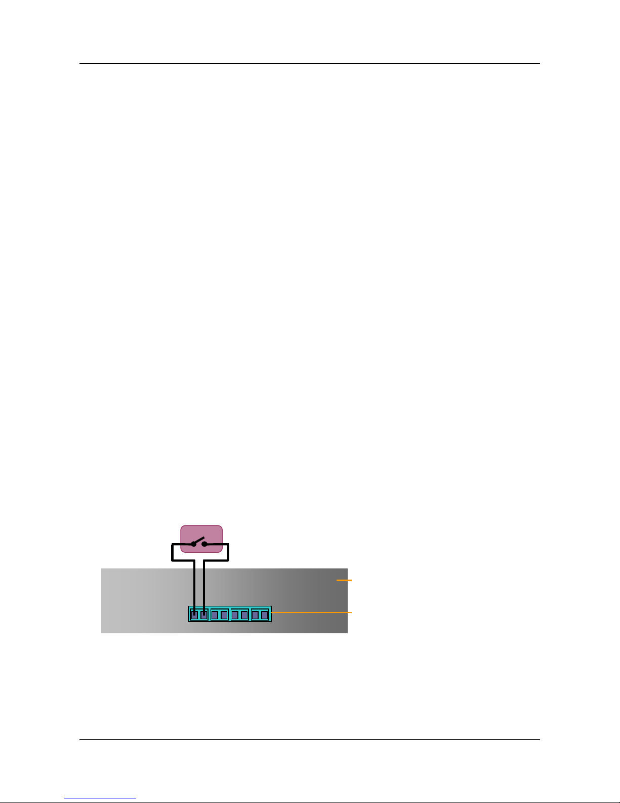
2. Connect the two wire con tacts of the s ensor or swit ch to the Sens ors termin al block on the rear pan el of t he
MVG400, as illustrated in figure 15. Insert the wires into the connectors and tighten the screws below each
connector to hold the wires in pl a ce .
Note: Th e wires must be connected t o t wo ad jacent con tacts in the s ame group ( e.g . the two contacts of
“In1”), but the polarity does not matter.
Figure 15: Connecti ng a sensor
3. If the sensor requires an external power supply, conn ect it to the vehi cle battery or anoth er power supply.
Note: You m ay be able to supply power to the sensor by connecting it to the 12VDC Power Out connector on
the rear panel of the unit (see Using the 12VDC Power Out Connector, page 38).
In1 In2 In3 In4
Sensor
Sensors terminal block
MVG400 rear panel
Page 19
SerVision MVG400 Installation Guide
Connecting Devices to the MVG 40 0 18
Conne cting Se nsors Using an A DAM Mod ule
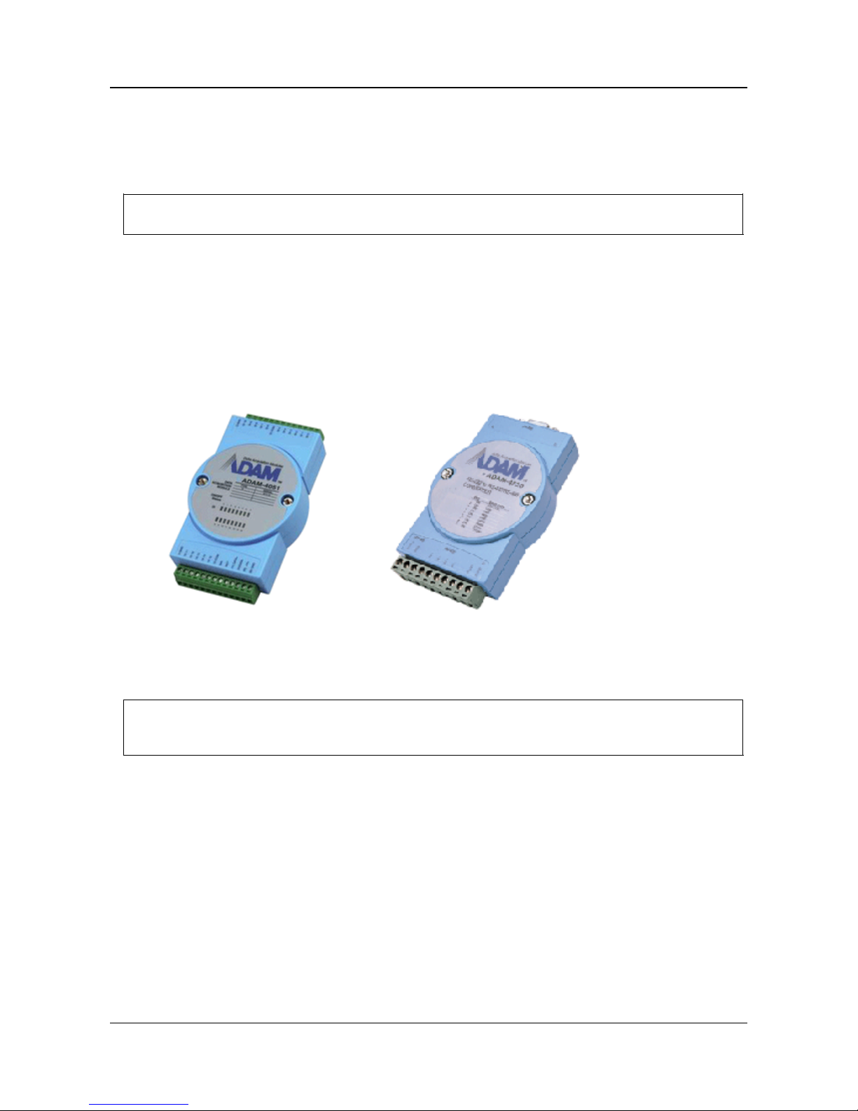
If you want to connect additional dry sensors to the MVG400, you can d o so b y connectin g an ADAM Data
Acquisition Module to the unit. Up to 16 additional dry sensors can then be connected to the unit through the
ADAM module.
NOTE: Alternatively, you can con nect addi tional s en sors using an IA-3126-2 relay board, as explained
Connecting Sensors and Activators Using an IA Relay Board, pag e 22.
To connect sensors using an ADAM module, you will need the following items:
• ADAM-4051 Data Acquisition Module (available from SerVision)
• ADAM-4520 isolated RS232->RS422/RS485 converter (available from SerVision)
• Flat ribbon c able with D -type 9-pin female conn ector on one end and a D-type 9-pin male connector on th e
other end
• Wire to connect th e A D AM m odu le to the ADAM converter – red , bl ack, yell o w, and green
• Wire an d an el ectrica l pl u g ( optional) to connect the ADAM modu le to a power source
Figure 16: ADAM-4051
module
Figure 17: ADAM-4520 isolated
converter
NOTE: The instructions below explain how to connect sensors to the MVG400 using the ADAM module and
converte r de s c ribed above. For addi t iona l information a bout con necting a nd config uring the A D A M
module and conver ter, plea se r efer to th e man u facturer 's documen tation, or contact your vend or.
To con nect sen sor s using a n ADAM module:
1. Install the sensors in their desired locations in accordance with the manufacturer's instructions.
2. Connect the wire conta cts of each of the sens ors to the terminal blocks of t he ADAM-4051 module as follows:
•
•
•
Connect all of the n ega tive (-) wires of all of the s ensors to one of th e groun d (D GND) connector s on th e
ADAM modu le. If the wires cannot all be inser ted into the connector, use a wire connector to connect
them together, and then connect the wire connector to the ground (D GND) connector on the AD AM
module.
•
•
•
Connect each of the positive (+) sensor wires to one of the numbered conn ect ors (D1 0 through D1 15) in
the terminal blocks of the module.
Page 20

SerVision MVG400 Installation Guide
Connecting Devices to the MVG 40 0 19
Figure 18: Connecti ng senso rs to the ADAM-4051 module
3. Connect the ADAM-4051 module to the ADAM-4520 isolated converter as follows (see figur e 20, page 21):
Connect this connec tor on
the ADAM-4051
To this connector on t he
ADAM-4520
(Y) Data+ Data+
(G) Data- Data(R) +Vs (R)+Vs
(B) GND (B)GND
4. Connect the ADAM-4520 isolated converter t o th e RS232/485 connector on the r ear p anel of the MVG400
uni t i n one of t he fol lowing ways:
•
•
•
If you are n ot connect i ng any RS485 P TZ controller s to the unit, using the 9 -pi n fla t ribbon cable, conne c t
the RS232 con nector of the ADAM-4520 conve rter directly into the RS232/485 connector.
•
•
•
If you are also connecting one or more RS485 PTZ controllers to the unit, using the 9-pin flat rib bon
cable, connect th e RS232 connector of th e ADAM-4520 converter int o the RS2 32 connector of t he
RS232/485 adapter supplied with the unit. Connect the PTZ controllers to the adapter as explained under
Connecting PTZ Controllers, page 15. Then plug the adapter into the RS232/485 connector on the unit.
D GND
Connect sensor ground
wires to this connector
D1 0
through
D1 10
Connect positive (+) sensor wires
to these connectors
D1 11
through
D1 15
Connect positive (+) sensor
wires to these connectors
D GND
Connect sensor ground
wires to this connector
Page 21
SerVision MVG400 Installation Guide
Connecting Devices to the MVG 40 0 20
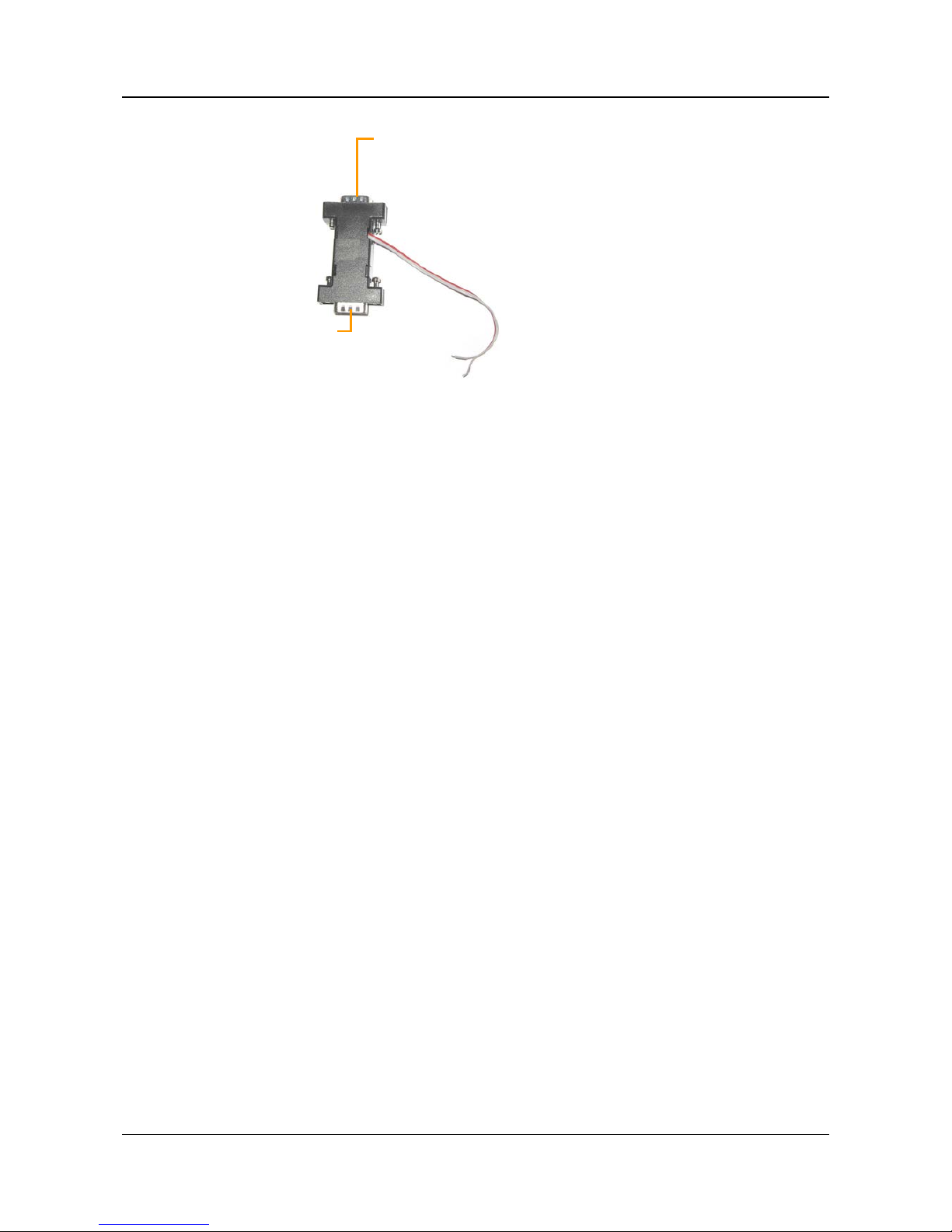
Figure 19: RS232/485 adapter
Note: If you connec t an ADA M module to t he uni t, you cannot con nect any RS232 PTZ con t roller s, a touchscreen contr oll er , or an IA relay board to the unit. For additional infor mation, see Connecting PTZ
Controllers, page 15; Connecting a CCTV Monitor, page 24; Connecting Sensors and Activators Using an IA
Relay Board, page 22.
5. Connect the ADAM-4051 module to the power source as follows (see figure 20, page 21):
•
•
•
Connect the positive (+) wire of the power supply cable to the (R) +Vs connector on the module
•
•
•
Connect the negative (-) wir e of th e power supp ly cable to the (B) GND connector on the module
Note: Ea ch of the power connector s on the modul e will then have t wo wires connected to i t – one connect ing
it to the power supply, and one connecting it to the power connectors of the ADAM-45 20 con ve rter.
Plug into RS232/485
connector on MVG400
RS232 connector
Page 22

SerVision MVG400 Installation Guide
Connecting Devices to the MVG 40 0 21
Note: You may be able to use t he MVG400 to supply power to the modules by connecting the power supply
cables to t he 12VDC Power Out connector on the rear pan el of the unit (see Using the 12VDC Power Out
Connector, page 38).
Figure 20: Connecting the module to the converter, the MVG400, and the power supply
Connecting Acti vators
Activators are ex ternal devices such as alarm s and lights th at can be turned on by th e s ystem in response to an
event. Essentially, the unit functions as an on/off switch for the device. The unit activates the activator by closing
the circuit of its power supply. Two activators can be connect ed directly to th e unit. In addition, if you wish, you
can conn ect an IA-3126-2 relay board to the unit. This mak e s it possible to connect up to 16 additional activators to
the un it (see Connecting Sensors and Activators Using an IA Relay Board, page 22).
In addition to the activator itself, you will n eed 1 6 AWG red and bla ck cables to con nect an a c t ivator to t he uni t.
To connect an activator:
1. Install the ac tivator in its d esired lo cation i n ac cordance with the ma nu factu re r 's instruct ions.
2. Connect the two contacts of the activator to the Activators termina l bl ock on the r ear panel of the MVG400, as
illustrated in figure 21.
Note: Th e wires must be connected t o t wo ad jacent con tacts in the s ame group ( e.g . the two cont acts of
“Out1”), but the polarity does not matter.
Connect to RS232/485
connector on the MVG
(Y) Data +
(G) Data -
(R) +Vs
(B) GND
Connect to power
supply (-)
Connect to power
supply (+)
Page 23
SerVision MVG400 Installation Guide
Connecting Devices to the MVG 40 0 22
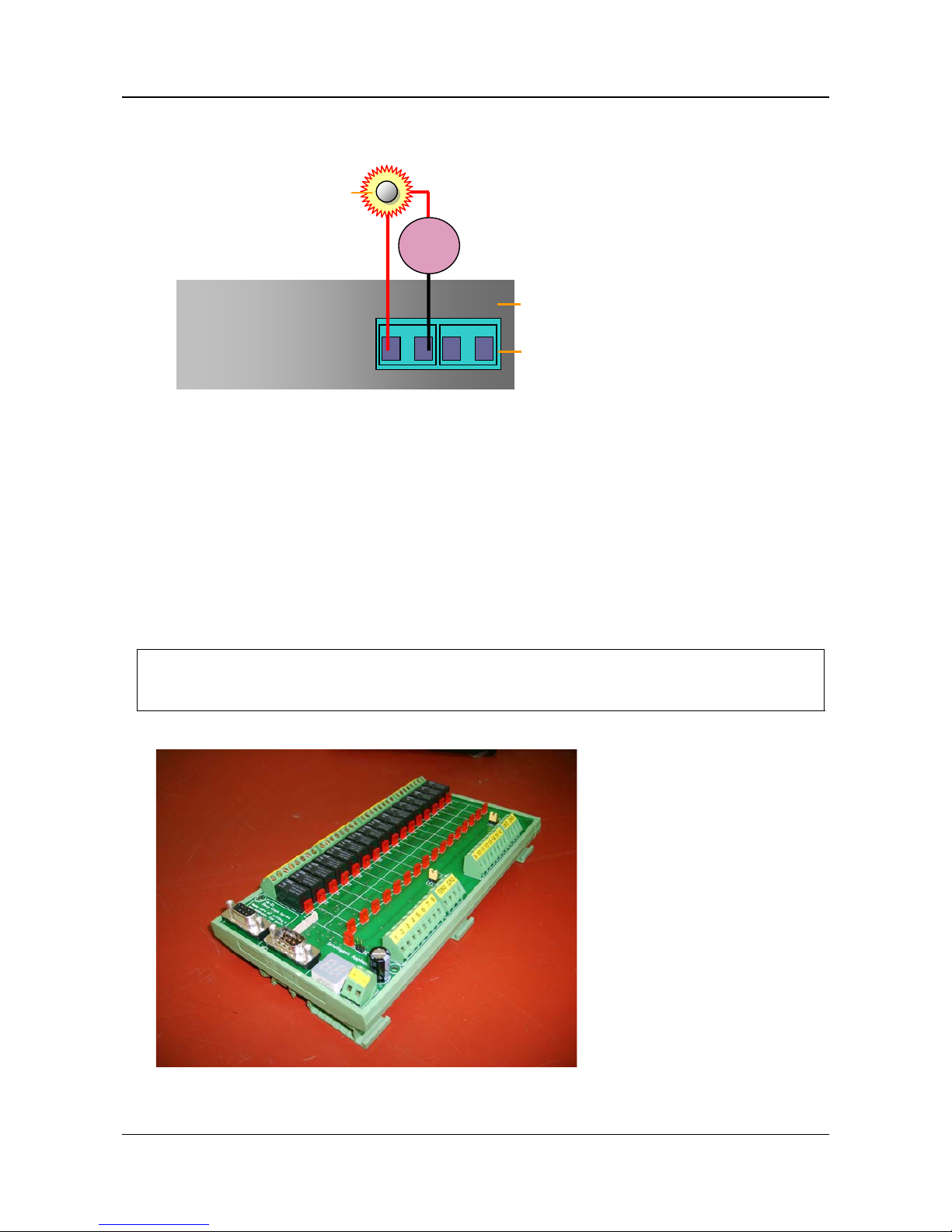
Figure 21: Connecting an activator that has its own power supply
3. Connect the activator to an external power supply, such as the vehicl e ba ttery.
Note: You m ay be able to supply power to the activator by connecting it to the 12VDC Power Out connector
on the rear panel of the u nit (see Using the 12VDC Power Out Connector, page 38).
Connecting Sensors and Activators Using an IA Relay Board
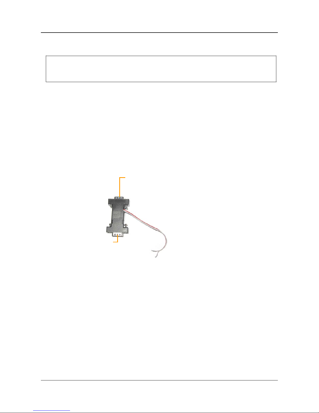
If you want to connect additional dr y sensors a nd/or activat ors to t he MVG400, you c an d o s o by connectin g an
Intelligent Appliance IA 3126-2 relay board to the un it. Up t o 16 additional dry sensor s a nd 16 addit ional activators
can th en be con nected to the unit through th e r ela y board. Sensor and act ivator events from d evi ces connect ed to an
IA rela y board can be seen in SerVision client applications and activa tors can be t ur ned on and off via these
applications. However, the sensors and activators cannot be configured using the MVG400’s configuration utility.
NOTE: Alternatively, you can con nect addi tional s en sors using an ADAM module, as explained under
Connecting Sensors Using an ADAM Module, page 18. Sensors th at are conn ected thr ou gh an ADAM
module can be config ured usin g th e MVG400’s configuration utility.
Figure 22: IA 3126-2 relay board
Out1 Out2
+ - + -
Activators
terminal block
+
Power
Activator
MVG rear pan el
Page 24
SerVision MVG400 Installation Guide
Connecting Devices to the MVG 40 0 23
For i nfor m ation about connect i ng s ensors and activators to the IA 3 126-2 relay board, and about connecting the
relay board to a power s ource, please consu lt the relay-board’s documentation.
NOTE: If you are connecting les s th an 16 activators or 1 6 sensors t o the r elay boar d, be sure to conn ect them to
the rel ay beginning with th e lowest conn ector, and do not leave open connect ors between those tha t
you use . For exa mple, if you a re con necting 4 a c tiva tor s and 3 sensors, connec t the ac tivators to output
connectors 1-4 on the board and the sensors to input connectors 1-3 on the board.
To connect the IA 3126-2 relay board to the MVG400:
1. Set the ID of the relay board to 0. (For information about how to do this, consult the relay-board
documentation.)
2. Connect the relay board to th e RS232/485 connect or on the rear p anel of the MVG400 unit in one of t he
following ways:
•
•
•
If you are n ot connect i ng any RS485 P TZ contr oller s to th e unit, usin g a 9-pin flat ribb on cable, con nect
the RS232 con nector of the relay board directly int o the RS232/485 connector.
•
•
•
If you are also conne cting one or more RS 485 PTZ con t rollers t o the un it, us i ng a 9-pin flat r ibbon c able,
connect the RS232 connector of the relay board into the RS232 connector of the RS232/485 adapter
supplied with the unit. Connect the PTZ controllers to the adapter as explained under Connecting PTZ
Controllers, page 15. T hen plug the adapter into the RS232/485 connector on the unit.
Figure 23: RS232/485 adapter
Note: If you connect a relay board to the unit, you can not c onnec t any RS2 32 PT Z c ontroll ers or a n ADAM
module to th e unit. F or ad dition al inform ation about connect ing P TZ cont rollers to th e un it, s e e Connecting
PTZ Controllers, page 15. F or in formation about c onnec tin g an ADA M module to the uni t , see Connecting
Sensors Using an ADAM Module, page 18.
Connecting Mic ro phones
Up to two mi cr op hones can be connect ed to the unit, one active and one passive. Wh en one or two microph ones are
connected, you can hear and record sound along with video images. The sound from a mi cr op hone can be
associa ted with any or all of th e ca meras in the unit’s configuration. (For additional information, please ref er to the
Embedded Video Gateway System G uide.)
Microph ones c an be connec ted to one or both of the Audio In con nector s (Ain1 and/or Ain2). Passive
microphones, which require external amplification, must be connected to Ain1. Active (sel f-amplifying)
microphones mu s t be connect ed to Ain2. Microphones with an output voltage of 1 Vrms or 1.41 Peak are
supported.
Plug into RS232/485 connector on
MVG400
RS232 connector
Page 25
SerVision MVG400 Installation Guide
Connecting Devices to the MVG 40 0 24
To con nect a microph one:
1. Install the microphone in the desired location.
2. Plug the micr ophone connector in to the desired Audio In connector (Ain1 or Ain2).
Connecting a Speaker or Headphones
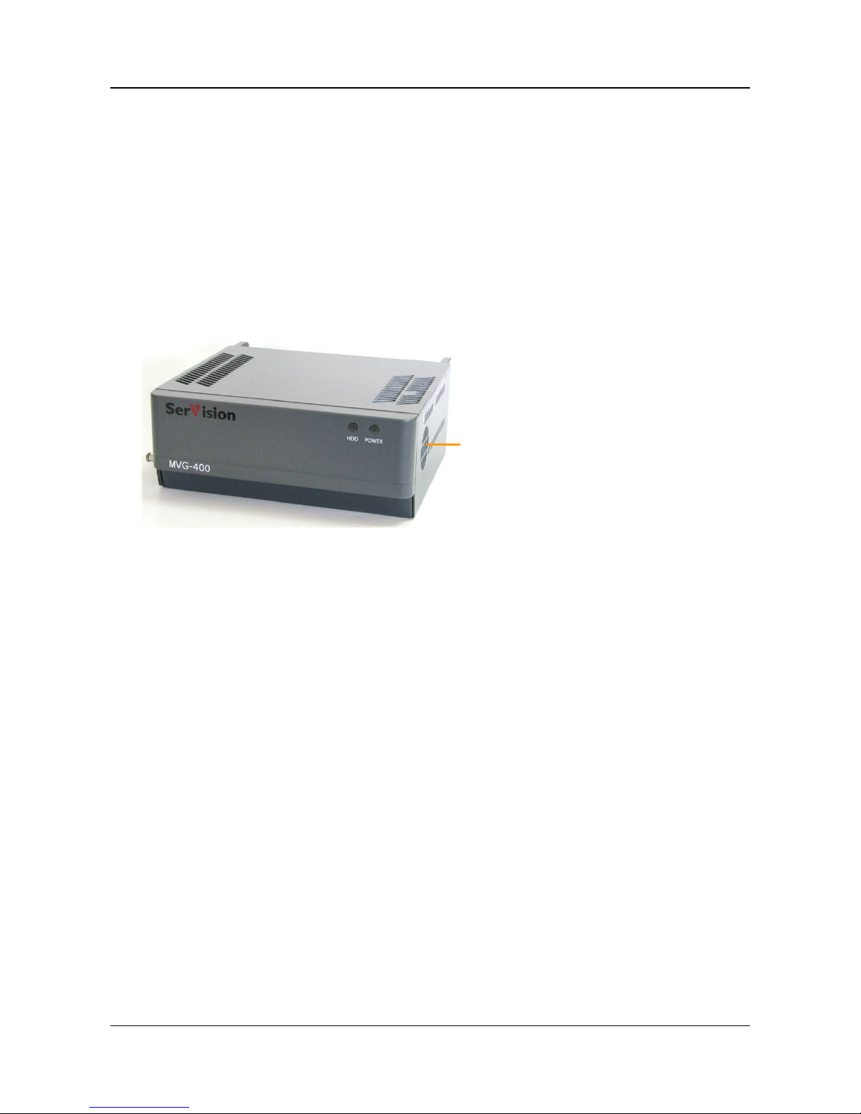
The MVG400 unit c ontains a built-in, 1-watt, internal speaker, which is located on the right side of the unit. You
can also connect an external s p eaker or head phones to the unit. The speakers (an d headphones ) allow you to hear
audio that is transmitted from one of the client applications. Th e ex ternal s p eaker or head phones can be u sed in
addition to the internal speaker or instead of it. (For addit i onal information, please refer to the Embedded Video
Gateway System Guide.)
Figure 24: Internal speak e r
To connect a speaker or headphones:
1. Install the speaker in it s d es ired locat ion, if n ecess ary.
2. Plug the speaker or hea dphone connector int o the Audio Out (Aout) connector.
3. If the speaker requires an external power supply, connect it to the vehicle ba ttery or another p ower supply.
Note: You m ay be able to supply power to the speaker by connecting it to the 12VDC Power Out connector
on the rear panel of the unit (see Using the 12VDC Power Out Connector, page 38).
Connecting a CCTV Monitor
You can connect a CCTV monitor to the unit. The monitor offers an alternative way to view live video from the
MVG400. It is primarily useful if you want to view video when the user is n ear the unit. For ex ample, i f the
MVG400 is set u p in a bu s, the driver can use a CCT V m onitor to k eep tabs on parts of the bus that cannot been
seen fr om th e dr iver’s seat.
The following types of monitors can be used:
• Surveillance monitors: Monitors that are designed to be plugged directly into surveillance cameras.
• Entertainment monitors: Monitors that are in tended to be plugged into portable DVD players in vehicles.
• Standard television sets with AV connectors
When choosing a monitor to connect to t he unit, ensure the m onit or sup ports the video forma t use d by the c ameras
(NTSC or PAL). Some SECAM monitors will also w ork wh e n the P AL vid e o format is used.
Intern al sp ea ker
Page 26
SerVision MVG400 Installation Guide
Connecting Devices to the MVG 40 0 25
If you choose a monitor with touchscreen support, you can use the monitor to view recor d ed video as well as live
video. For information about recommended types of touch s creen monitors, plea se con s ult your vendor.
NOTE: If you are con necting an RS232 PTZ contr oller or an ADAM module t o t he unit, you c annot use
touchscreen functi on ality because the RS232 serial port is not available. F or additional information, s e e
Connecting PTZ Controllers, page 15; Connecting Sensors Using an ADAM Module , page 18.
To connec t the m onit or to the MVG400, you will need a cable wit h the following conn ectors:
• An a ppropr iate conn e c tor (BNC or RCA) for the Vide o In connector of the monitor. (Consult the monitor
documentation or your vendor to find out which kind of connector is required for the parti cu lar monitor you
are using.)
• A BNC male con nector to connect to the TV Out connector of the MVG400. ( A ca bl e wi t h an RCA connector
can be used by attaching a BNC-to-RCA adapter to the connector. See figure 12, page 15.)
To conn ect the outp ut of a touchscr een to the unit, you will need a cable with the following connectors:
• An a ppropr iate conn e c tor to connect t o t he t ouch output c onnec tor on the monit or
• A female 9 -pi n RS2 32 connect or to c onnec t to the MVG400’s RS232/485 connector.
An appr opriate cable should be supplied with the monitor.
To connect a CCTV monitor:
1. Install the monitor in its desired location.
2. Connec t th e Video In connect or of the mon i tor t o t he TV Out connector of the MVG400, using a ca ble with
an appropria te connector (BN C or RC A) for the Video In conn e c tor of t he mon itor on one end, and a BNC
male connector on the other end.
Note: If you are using a standard tel evision s et as a monitor , use the t elevision ’s AV connect or as the Vi d eo
In put connect or.
3. If the monitor is touch-sensitive, conn ect the touch out put to the RS232/485 connector a s f oll ows:
•
•
•
If you are n ot con necting any RS485 PTZ contr ol lers to the unit, connect the RS23 2 connector of the
touch output c able direct ly into th e RS232/485 connector.
•
•
•
If you are also conne cting one or more RS 485 PTZ con t rollers t o the un it, connect the RS2 32 connector
of the touch output cabl e to the RS232 connector of the RS232/485 adapter suppl ied with the unit (see
figure 25 below). C on nect the PTZ control lers to the adapter as explained under Connecting PTZ
Controllers, page 15. T hen plug the adapter into the RS232/485 connector on the unit.
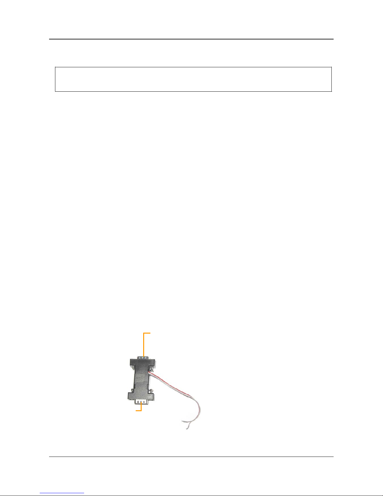
Figure 25: RS232/485 adapter
Plug into RS232/485
connector on MVG400
RS232 connector
Page 27

SerVision MVG400 Installation Guide
Connecting Devices to the MVG 40 0 26
4. Connect the monitor to the vehi cl e ba ttery or another power s u p p ly.
Note: You m ay be able to supply power to the monitor by conn ecting it to the 12VDC Power Out connector
on the rear panel of the unit (see Using the 12VDC Power Out Connector, page 38).
5. If the monitor is touch-sensitive, it i s recommend e d tha t you cal ibra te it before you us e it. F or in forma t ion
about how to calibrate th e monitor, please refer to the monitor ’s documen tation.
Connecting a Switch
If you wi sh , you can connect a swit ch to the unit to change the display on the monitor. The switch must be
connected to the Sensor 4 (In4) c onnec tor. For a dditional i nformation, se e Connecting Sensors, pag e 17 and refer to
the Embed ded Video Gateway System Guide.
Connecting Multiple Monitors
If you wish, you can connect multiple CCTV monitors to the MVG400. F or example , you ma y wis h t o have on e
mon i tor beside the driver’s se at and anot her beside the conduct or’s seat.
To con n ect multiple monitors, you must use video splitters to split the connection. Bear in mind, however, that the
image quality in each of the monitors will be slightly degraded. To correct this problem, you can use a video
amplifier (booster) for each monitor. To ensure you have t he cor rect equipment, con sult a video equipment supplier.
Page 28
SerVision MVG400 Installation Guide
Setting Up Network Connections 27
Setting Up Network Connections
The MVG400 has a built-in router that is used to connect the video-gat e way com pone nt of t he unit to external
networ k s such as the int ernet or a cel lular net wor k . The router can conn ect t o more than on e ex ternal n etwor k at a
time. For example, it can connect to a cellular n etwork and to a LAN simultaneously.
The router manages a small loca l network ( LA N ) th at can include up to four devi ces – the Vi deo Gatewa y itself and
up to thr ee ot her devices . For example, you coul d connect a PC and an IP-ba sed cash box t o t he router, an d t hey
would both be part of the MVG400’s LAN. The devices conn ected to th e router can connect to external n etworks
through the router. In addition, the router can be con figured to all ow connections from e xternal networ ks to the
devices in the internal network.
NOTE: The router is configured using the MVG400’s configuration utility. For additional information, please
refer to the Embedde d V ide o G ateway System Guide.
Connecting the MVG400 to an External Networ k
You can connect th e router to a LAN, a cellular network, an d/ or a WiFi access p oi nt. This section explains how to
set up th e unit so that th e r ou t er can be used by the MVG400 un i t to connect to these n e tworks. In order for t he uni t
to connect to the n etworks, it mu s t also be configured as ex pla ined in th e Embedded Video Gateway System Guide.)
To enable the MVG400 unit to connect to an external LAN:
• Connect the Ethernet Out connector on the rear panel of the MVG400 unit to a L A N c onnec tion point (a hub,
wall socket, or any other conn ection point) using the suppli ed Ethernet (network) ca bl e.
To enable the MVG400 unit to connect to an external cellular network:
• Connect a supported cellular modem that has a USB adapter to the USB port on t he rear of the uni t. To en s ure
good reception, use a USB ext ension cord to connect the modem to the USB port, an d p lace the modem in a
relatively exposed location as h igh up in the veh icle as possible. The USB e xtensi on cord shou ld not be lon ger
than 1.5 meters.
Note: In most cases, remote client d evi ces cannot con nect dir ectly to the unit over a cellular network. If you
want to u se a cellular n etwork to connect t o the MVG400, you wi ll pr obabl y have to use a SerV isi on proxy
se rver. For addit i onal information, please refer to the Embedded Video Gateway System Guide or conta c t your
vendor.
To enable the MVG400 unit to connect to WiFi access points:
• Connect the two supplied WiFi antennas to th e WiFi Antenna connectors on the rear of the unit.
Connecting Devices to the MVG400’s Internal Network
Up to three IP-based devices can be connected to the MVG400’s local net work. The MVG400’s rou t er contains a
DHCP server that can automatical l y assign IP addresses to devices that are plugged into its Ethernet ports. If you
will not need to access a connected device rem otely, you can configure the device to acquire its IP from this DHCP
server . In this case, the device will be able to conn ect to the extern al network, but rem ot e devices wil l not be able t o
access it . If you want to access th e device remotely, you should man u ally configure its IP address and other network
settings, as described bel o w, and set up por t forwar ding for the d evice as descr ibed in the E mbedded Video Gateway
System Guide under Port Forwarding.
NOTE: The Video Gateway compon e nt of t he MVG400 au tomati call y connect s t o th e r ou t er component when
the unit starts up. The router ' s DHCP server assigns an IP address to the Video Gateway component
and port forwarding is automatically configured.
Page 29
SerVision MVG400 Installation Guide
Setting Up Network Connections 28
To connect a device to the MVG400’s local ne twork:
• Connect the network connector of the device t o one of the Ethernet In connectors on th e r ear panel of the
MVG400.
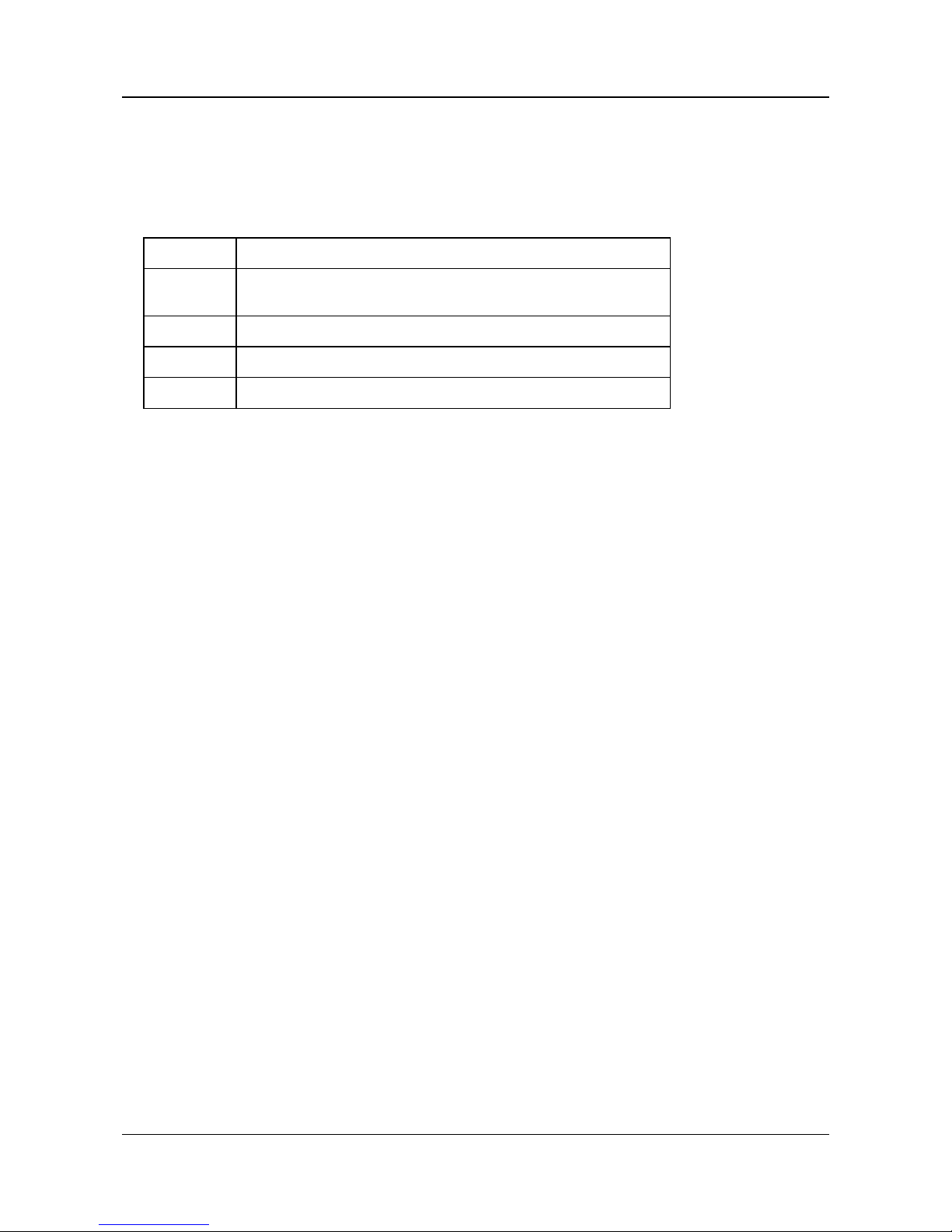
If you are configuring the device to enable remote access to it, set its network settin gs as follows. (For information
about h ow to configure the net wor k s et tings of th e d evi ce, cons ul t the device’ s d ocu ment ation.)
Setting Value
IP A ddres s
Assign a stati c IP address to the device. The IP m ust be in the range
172.20.233.2 through 172.20.233.99.
Mask
255.255.255.0
Gateway
172.20.233.1
DNS
172.20.233.1
Page 30
SerVision MVG400 Installation Guide
Connecting the GPS Antenna 29
Connecting the GPS Antenna
A GPS receiv er is built into th e un it. When th e GPS an tenna is connected t o the unit, this receiver can be used t o
track the location of the vehicle in which the MVG400 is installed.
To connect the GPS antenna:
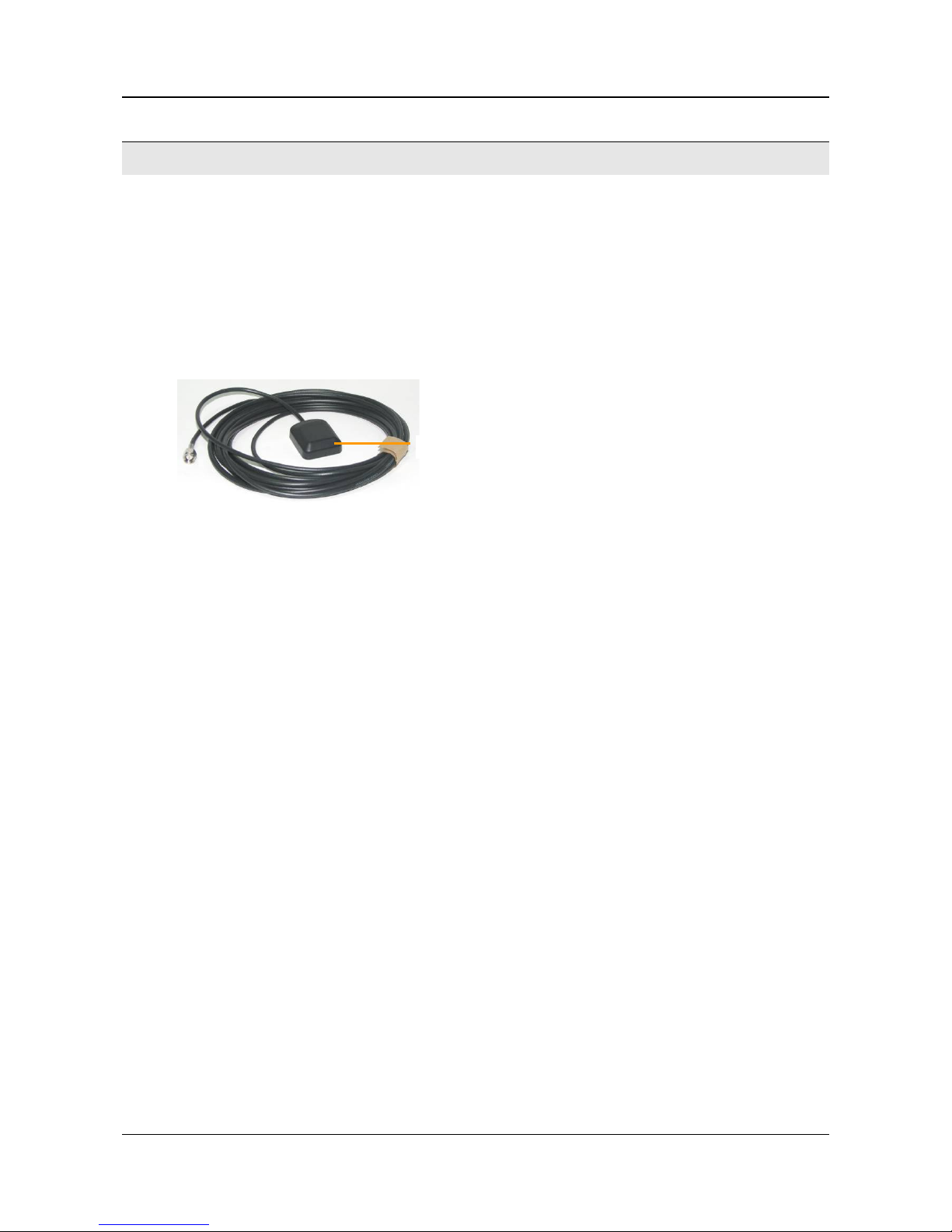
1. Connect the supplied GP S an tenna cabl e to the GPS Antenna con nector on the rear of th e unit.
2. Place the other end of th e an tenna as high up as possi bl e in the vehicl e or on the roof of the vehicle. Make sure
the box at the end of the antenna is horizontal and is facing up (smaller side up). I f p ossible, p la ce it in a
location in whic h there are no obstructions between it and the sky.
Figure 26: GPS antenna cable
The box at the end of the antenna contains a magnet with which you may be able to attach it to the roof of the
vehicle. Alternatively, you can attach it in its intended location with dou ble-sided tape. Regardl ess of which
method you use, make sure the antenn a is attach ed s ecu rely to the vehicle s o that it will not come loos e when
the vehicle moves.
Box facing up
Page 31
SerVision MVG400 Installation Guide
Connecting the MVG400 to a Power Source 30
Connecting the MVG400 to a Power Source
The Power connector of the MVG400 can be connected ei th er to the vehicle ba ttery or to a stan d ard electrical
outlet. Once it is connected, it starts up automatically. During the start-up process, th e L EDs on the fr ont of the unit
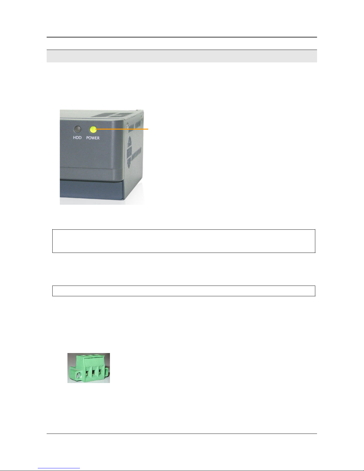
flash at various intervals. When the start-up process is completed successfully, the Power LED should display a s a
soli d color and blink mome ntarily e very secon d. (Depen ding on t he configuration s e t tin gs, it shoul d either be s olid
orange and then blink green or solid green and then blink orange.)
Figure 27: Power LED
NOTE: When the start-up process is com p leted, if the Power LED does not flash – if it disp la ys as a solid
green or orange all th e time – the start-up process was not successful. In thi s case, di sconnect the unit
from the power supply and then reconnect it.
Typicall y, the MVG400 unit is confi g ured in an office setting and then installed in th e veh icle. Th e p ower -supply
and power-connector ca bl es are used to con nect the un it to a standard electric outl et for confi g ur a tion. Aft er
configu rati on, the cables are disconnected from the unit, so that it can be connect ed to the vehicle battery.
NOTE: It is recommended that only a vehicle installation specialist connect the unit t o th e ba ttery.
Connecting the Wir e Connector to the Unit
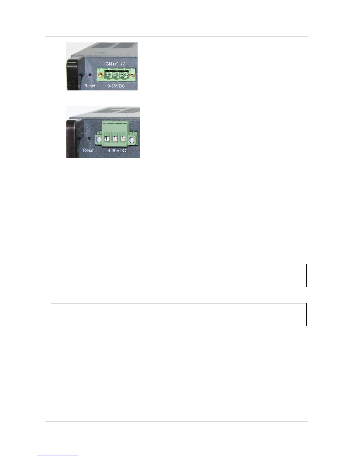
Demo uni ts and small ord ers are su pp lied withou t a wire conn ector in the Power con nector on the rear panel of the
unit, as in figure 29. In large or d ers, the uni ts are supplied with wir e-connectors connected to th e Power connectors
on the units, as in figure 30 (because only a limited number of power-con nector cables ar e supplied with larg e
ord ers, and ev ery uni t requi res a wire conn ector).
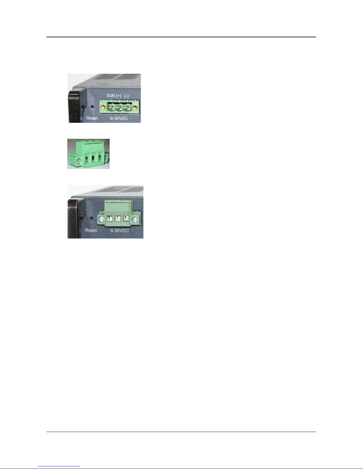
Figure 28: Wire connector
Power LED
Page 32
SerVision MVG400 Installation Guide
Connecting the MVG400 to a Power Source 31
Figure 29: No wire connector connected to Power connector
Figure 30: Wire connector connected to Power connector
In ord er t o connect the unit to the vehicle bat tery, the wire conn ector must be connected to the Power conne ctor on
the unit . Ther e fore, if your unit was s uppl ied as a demo un it or a s part of a small or der, you mus t remove th e wire
connector from the power-connector cable and connect it to the unit.
To connect the wire connector to the unit:
• Plug th e wire conn ector into the Power connector on th e rear panel of the unit, and tighten the screws to
secure it.
Connecting the Unit to an Electrical Outlet
If a stan dard electrical outlet is ava ilable, the unit can be con nected to it. For example, i f you want to confi g ure or
test the unit indoors, you can power the unit in this way.
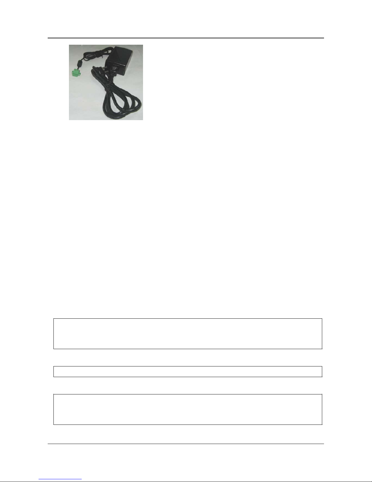
WARNING: Only the power supply ca ble that came with the unit (or with the shipment) should be used t o
connect the unit t o an electri ca l ou tlet. Use of a power supply other than the one provided in the
packa g e may cause irr ep arable damage to th e unit.
NOTE: If the unit was supplied as part of a large order, powe r-supply and power-connector cables wer e n ot
suppl ied for each individu al unit. The cables that were sup pl ied s hould be r eu s ed for all the un its (see
The MVG400 Pack age, page 4).
To connect the MVG400 to a sta ndard electrical outlet:
1. Connect the power-conn ector cable t o the power-supply cable.
Page 33
SerVision MVG400 Installation Guide
Connecting the MVG400 to a Power Source 32
2. If a wire connector is connected to the Power connector on the unit, unscrew th e s cr ew holdin g it in place, and
remove it.
3. Connect the power su p pl y cable to the Power connector on the unit.
4. Plug the power-connector cable into the outlet.
Connecting the Unit to the Vehicle Ba ttery
Normally, the unit is connected to the vehicle battery an d to the ignition usin g 16 AWG cable (not supplied). This
can be done i n one of two ways:
• Connecti ng the unit directly to the battery and the ign ition
• Connect ing the unit to a power source in the vehicle th at is only acti ve when the ignition is on
When the un it is connected to th e ba ttery and ign ition in one of t hese ways, it automaticall y pow ers up when th e
ignition is switched on . I f the unit i s connected directl y to the battery, it can be configured to operate only when the
vehicle ignition is on or to shut down automatically soon after the ignition is turned off. Otherwise, it will shut
down auto matically whe n the ign i tion is turned of f.
For testing and evaluati on p urposes, the unit can also be power ed b y connecting it to the vehicle’s cigarette lighter ,
if the vehicle has one. This meth od connects the unit to the batter y and the ignition quickly and easily, but it is not
normally suitable for permanent connections, because it is difficult to install the unit and the wiring securely in
appropriate locations when this method is used.
In addition, it is possible to connect the un it to the battery alone, without connecting it to the ignition. In this case,
the unit runs contin uously, whether the igni t ion is on or not, a s long as the battery can supply power to it. Because
of the drain on the battery, connecting the unit in this way is also only recommended for limited periods of time for
testing and eva luati on purposes.
NOTE: The igni t ion con nector ( IGN) of the Power connector MUST be connected. If it is not, the un it will not
start. If you wish to use the vehicle’s ignition connection, connect it to this connector. Otherwise, short
this con necti on to the positi ve (+) con nector of the Power conn e c tor bl ock. For additional information,
see step 4 below (pp. 33–34).
NOTE: To connect the unit only to the battery, 16 AWG r ed and black cabl e ( not supp lied) is req u ired.
WARNING: It is very impor tan t to ensur e th at the unit i s connected t o the power source in such a wa y that there
are no voltage fluctuations when the unit is in operation. Voltage fluctuations can interfere with the
timestamps of recorded video, making it impossible to r etrieve the video from the unit's storage
media.
Page 34
SerVision MVG400 Installation Guide
Connecting the MVG400 to a Power Source 33
To connect the MVG400 to the vehicle battery:
1. If the wir e connector is not plugged into the Power connector on the unit, plug it into the Power connector on
the rear panel of the unit, and tighten th e screws to secure it.
Figure 31: No wire connector plugged into Power connector
Figure 32: Wire connector
Figure 33: Wire connector plugg ed int o Power connec t o r
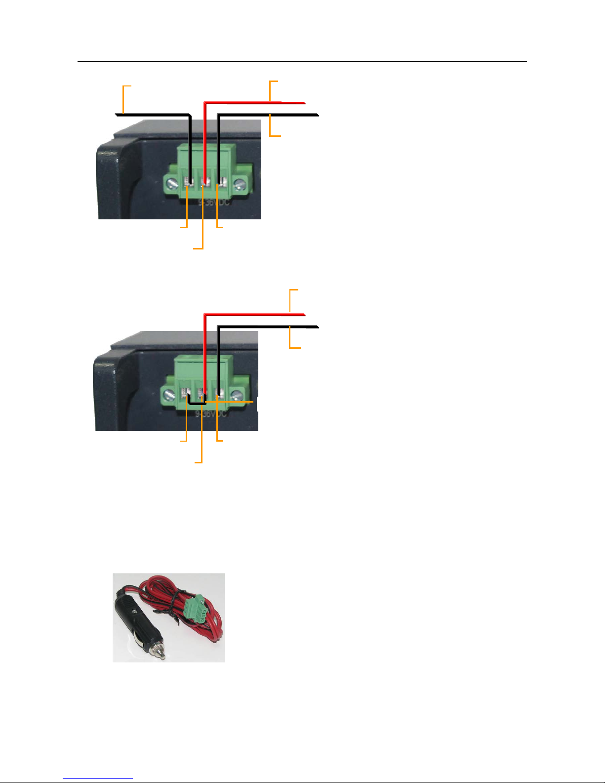
2. Using 16 AWG red cable, conn ect the unit to the vehi cle battery as follows:
•
•
•
Connect one end of th e r ed wire to the positive (+) connect or of t he Power wire connect or (the mi d dl e
connector in th e bl ock).
•
•
•
Connect the other end of the red wire to the positive (+) connector of the vehicle ba ttery or power s ource
3. Using 16 AWG black cable, con nect the unit to the vehicle bat tery as follows:
•
•
•
Connect one end of th e bl ack wire to th e n egative (-) connector of the Power wire connector (the right
connector in th e bl ock).
•
•
•
Connect the other en d of the black wire to the nega tive (-) connector of the vehicl e ba ttery or power
source
4. If you need to connect the unit to the ignition, using 16 AWG black cable, connect the IGN connector to the
ignitio n, as illustrated in figure 34. If you do not need t o connect the unit to the i gnition, using 16 AWG black
cable, connect the IGN connector to the positive (+ ) con nector of the Power conn ector (th e middle connector
in the block), as illustrated in figure 35.
Page 35
SerVision MVG400 Installation Guide
Connecting the MVG400 to a Power Source 34
Figure 34: Connec t i ng the MVG400 to the vehicle battery and the ignition
Figure 35: Connect i ng the IGN connector to the (+) connector when a connection to the igniti o n is not
required
To connect the MVG400 to the vehicle’s cigarette lighter:
• Use th e s upp lied power cord to connect the Power connector on the rear panel of the uni t to the vehi cl e’s
cigarette lighter.
Figure 36: Power cord
(+) connector
(-) connector
IGN
connector
Connect to negative (-)
battery connector
Connect to positive (+)
battery connector
Connect to
the ignition
(+) connector
(-) connector
IGN
connector
Connect to negative (-)
battery connector
Wire connecting
IGN
to (+)
Connect to positive (+)
battery connector
Page 36

SerVision MVG400 Installation Guide
Connecting the MVG400 to a Power Source 35
NOTE: Power cords are normally onl y supplied with demo units.
NOTE: If a wire conn ector is already connected to th e Power connector, remove it bef ore you connect the
power cord.
Page 37

SerVision MVG400 Installation Guide
Appendix 1: Removing the Unit ’s Hard Dr ive 36
Appendix 1: Removing the Unit’s Hard Drive
The hard drive of the MVG400 can easily be removed and r ep laced with another one. This may be a conveni en t
way to review or download video from t he hard dr ive. F or example, if MVG400 units are installed in a fleet of
buses, you may want to remove the hard dri ve from each bus when it comes into the bus depot, and replace it wi t h a
differ ent hard drive. You can then inser t the hard dri ve into an MVG400 at the ya rd office and view or download
the video from it.
NOTE: For information abou t acq uiring additional hard drives that are com patible wi t h the MVG400, please
cons ult your MVG400 vendor or SerVision technical support.
To remove the hard drive from the MVG400 unit:
1. Disconnect the MVG400 from the power supply.
2. On th e left side of the unit, use the key that was supplied with the unit to unlock the cover of the hard-drive
compartment, and then remove th e cover.
Figure 37: Hard-driv e compartment cover
3. Loosen the screws that s ecu re the hard-drive platform in the compartment.
Hard-drive
compartment cover
Unlock
Page 38

SerVision MVG400 Installation Guide
Appendix 1: Removing the Unit ’s Hard Dr ive 37
Figure 38: Hard-drive plaform in open compartment
4. Pull the hard-drive platform out of t he un it.
Figure 39: Hard drive on platform
To insert a hard drive into the unit:
1. Slide the hard-drive platform into the hard-drive compartment.
2. Tighten the screws that secure the platform in the compartment (see fi g ure 38).
3. Place the compartment cover over the compartment, and secur e it in pl ace by locking the lock (see figure 37).
Hard drive
Platform
Screw
Platform – pull to remove hard drive
Screw
Page 39
SerVision MVG400 Installation Guide
Appendix 2: Using the 12VDC Pow er Ou t Connec tor 38
Appendix 2: Using the 12VDC Power Out Connector
The MVG400 can suppl y power from the vehicle battery directly to devices via the 1 2VDC Power Out connector
on the rear panel of the unit. However, only a limited amount of power can be supplied by the MVG400 in this way.
If the devi ces connected t o the 1 2VDC Power Out connector draw a tot al of more th a n 500 mA at one time, the
unit may overheat or otherwise malfunction. Therefore, it is best to provide independent power supplies for devices
connected to the unit whenever possible by connecting them directly to the vehicle battery (or some other power
source), a s ex pl ained above (see Supplying Powe r to Devices Connected to the Unit, page 12).
Nonetheless, in certain cases it may be a dvantageous to supply power to one or more devices thr ough the 12VDC
Power Out connector. It is not recommended to use the connector to supply power t o ca meras. If you are interested
in connecting other devices to the conn ector, pl ease consult a SerVision techn ician (at [email protected]
) to
discuss the feasibility of c on necting them. Bear in mind that the MVG400 unit c a n sup ply a maximum of 500 mA
(6W at 12V) of power thro ugh the 12VDC Power Out connector. Before you contact technical support, co nsult the
device docu mentation of each device you want to connect to the MVG400 unit to ascert ain its actual power usage.
NOTE: Devices that draw their power through the 12VDC Power Out connector on t he MVG400 are turned
off automatically when the MVG400 shuts down, becau s e th ey do not recei v e any power from the unit
whe n it is off .
WARNING: It is not recommended to use the 12VDC Power Out connector to supply power to cameras.
Page 40
MVG400 Installation Guide
POB 4520 5 Jeru s alem 91450 Israel
Tel: +972-2-535 0000 • Fax: +972-2-586 8683
www.servision.net • [email protected]
 Loading...