

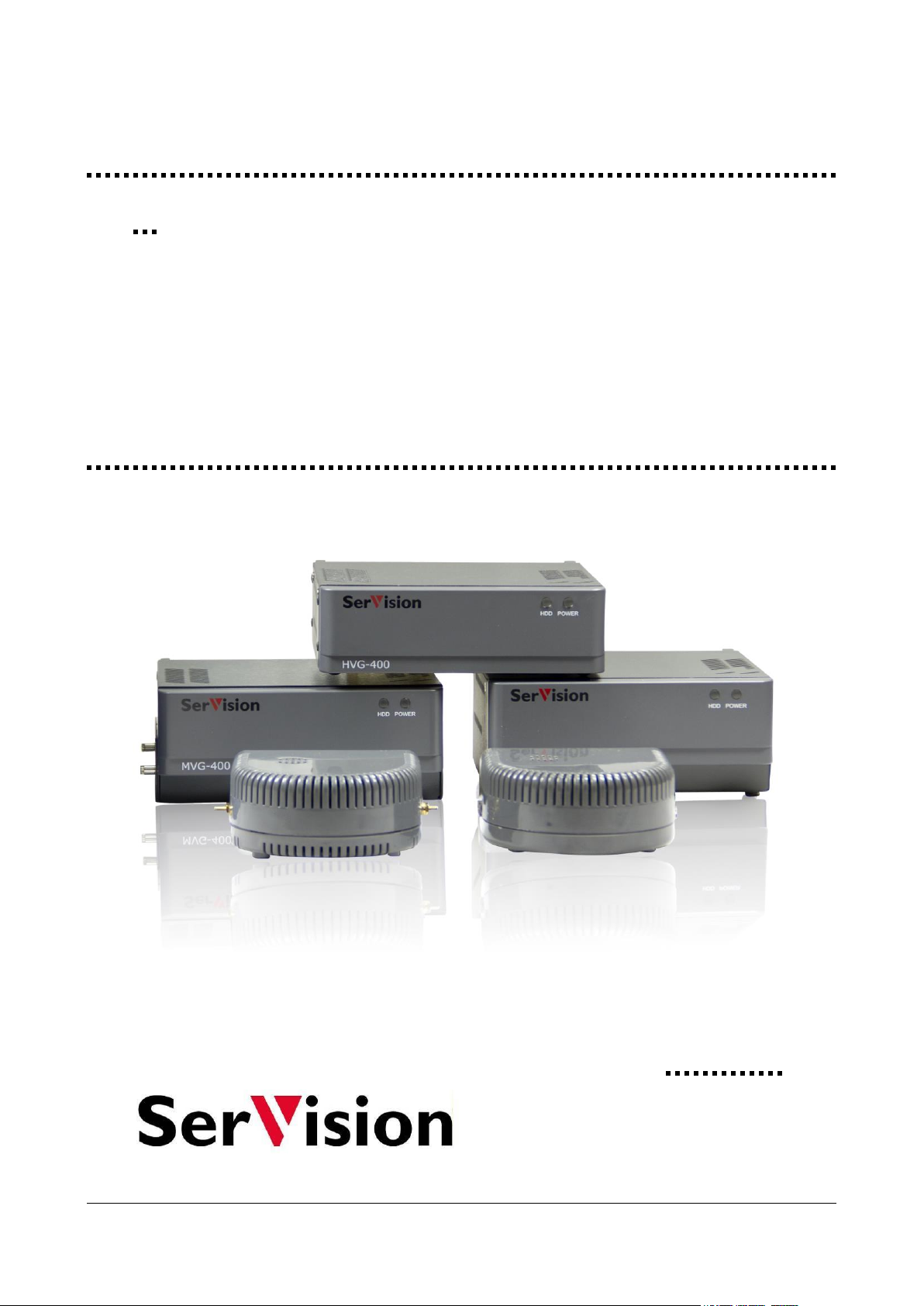
SerVision HVG400, UVG400, CVG, CVG-M, MVG200 Configuration And Management Manual
...
Embedded Video
May
2015
Gateway
System Guide
Configuration and management guide for SerVision
HVG400, UVG400, MVG200, MVG400, CVG, and CVG-M
Video Gateway models

SerVision Embedded Video Gateway System Guide
Trademarks & Copyright
Trademarks
All trademarks mentioned in this manual are the sole property of their respective manufacturers.
Copyright
SerVision Ltd., Jerusalem, Israel
www.servision.net • info@servision.net
© 2015 SerVision Ltd. All rights reserved.
Notice
Information in this document is subject to change without notice. SerVision Ltd. assumes no responsibility for any
errors that may appear in this manual. Companies, names and data used in examples herein are fictitious unless
otherwise noted. No part of this document may be copied or reproduced in any form, or by any means, electronic or
mechanical, for any purpose, without the express written permission of SerVision Ltd. SerVision Ltd. makes no
warranties with respect to this documentation and disclaims any implied warranties of merchantability or fitness for
a particular purpose.
sw CVG-M: v H1.2.2.26a.99
sw MVG200: v H1.2.2.26.a97
sw 4-channel: v HM4.2.2.26.a92
doc v 1-9
1

SerVision Embedded Video Gateway System Guide
Table of Contents
Getting Started 5
About this Guide 5
About Client Software 6
Before You Begin 6
Installing SVMultiClient 7
Opening the Configuration Utility 8
Overview of the Interface 10
Top-Level Menu Options 10
Status Bar 11
Using the Configuration Utility 11
Opening the Configuration Remotely 14
Opening the Configuration Manually 14
Configuring System Settings 16
General System Settings 17
About the General System Settings 17
Configuring General System Settings 21
Configuring a CCTV Monitor (TV-Out) 25
Configuring the Monitor to Display Video from the Video Gateway 26
Configuring the Monitor to Play Prerecorded Video 30
Setting the Unit Time 33
Updating the Date and Time Manually 35
Configuring Automatic Time Setting 37
LAN Settings 38
Modem 40
Video Gateway with Router 41
CVG-M 45
WiFi 47
Configuring the Unit to Connect to WiFi Access Points 47
Removing an Access Point from the List 52
Turning WiFi Off 52
Configuring the Unit to Function as an Access Point 53
Network Priorities 54
Port Forwarding 55
Proxy and DDNS Settings 57
Authentication 60
SMS and E-mail Notifications 61
SMS Message Templates 66
Testing Notification Settings 67
Automatically Uploading Video to an AVV Server 67
Viewing the List of Files on the AVV Server 72
Viewing Video from the AVV server 72
Disabling AVV 74
FTP Server Settings 74
Schedules 76
Configuring a Standard Weekly Schedule 78
Defining Holiday Schedules 80
2

SerVision Embedded Video Gateway System Guide
Defining a New Schedule Row 83
Audio Settings 85
Configuring Microphone and Speaker Volume 86
GPS 88
Configuring GPS 88
Erasing Recorded GPS Data 90
Configuring Camera Settings 91
About Brightness and Contrast Settings 91
Configuring Video Cameras 91
Configuring PTZ 95
Video Motion Detection (VMD) 96
About VMD Regions 96
About VMD Event Settings 96
About Responses to VMD Events 97
Configuring VMD Settings 97
Configuring Video Lost 102
Video Recording Settings 104
Configuring Video Recording 105
Advanced Recorder Settings 106
Restoring Default Recording Settings 110
Erasing Recorded Video 113
Erasing All Recorded Video from a Camera 113
Erasing All Recorded Video from the Storage Media 114
Restoring the Default Disk Allocation 116
Configuring Sensor and Activator Settings 119
Configuring Sensors and Activators 119
Configuring Sensor 1 to Switch Outlines 125
Configuring a Sensor to Control CCTV Display 126
Configuring an Activator as a Power Switch 127
Configuring Vehicle-Behavior Sensors 128
Configuring a Geo-Fence Sensor 128
Configuring a Speed-Limit Sensor 145
Configuring an Idle Monitor 146
Configuring a G-Force Sensor 147
Defining Alternate Outlines 149
Creating an Outline 149
Activating Outlines Manually 154
Saving Configuration Changes 156
Discarding Changes 158
Restoring Default Settings 159
Connecting to the Video Gateway 163
Connecting Through SVMultiClient 163
Connecting through the Configuration Utility 165
Viewing Events 166
Viewing Snapshots 168
System Diagnostics 171
System Statistics 172
Testing Remote Connections 173
Ping 173
Traceroute 176
3

SerVision Embedded Video Gateway System Guide
Maintenance 181
Upgrading the Firmware 183
Upgrading Firmware via a TVG Upload Server 183
Upgrading Firmware via the TVG Download Utility 185
Required Files 185
Downloading the Firmware to the Unit 185
Catch Boot Operation 187
Upgrading Router Firmware 191
Modifying the AES Key 192
Resetting the Unit 197
Restoring Factory Settings 198
Troubleshooting 201
Appendix A: Viewing Video on a CCTV Monitor (TV-Out) 207
Using Mouse/Touch Controls 209
Setting the Video Display Layout 211
Playing Back Recorded Video 212
Editing and Downloading Video Excerpts 217
Configuring Display Options 226
Viewing System Information on the Monitor 233
Using PTZ Controls 233
Recording Status Display 235
Appendix B: LAN Settings 237
About the Local IP Address of the Unit 237
About the Public IP Address of the Unit 237
Appendix C: Networks Managed by SerVision Routers 238
Appendix D: Power LED Behaviors 239
4

SerVision Embedded Video Gateway System Guide
Getting Started
SerVision’s embedded Video Gateways are compact Video Gateway units that provide state-of-the-art security
functionality for a wide range of environments, from offices and homes to vehicles and other moving platforms. All
units feature live video streaming, video recording and playback, motion detection, sensor management, and realtime event notification and device activation. These features can be accessed remotely via PC, PDA, or cellular
telephone.
All Video Gateway units can connect to computer networks, including local networks and the internet, using cablebased Ethernet connections. Some models also support wireless network connections via cellular networks and
WiFi. In addition, mobile models support GPS tracking, and can be integrated with some third-party fleetmanagement systems.
The following embedded Video Gateway models are currently available:
HVG400: A four-channel Video Gateway optimized for homes and small offices. The HVG400 features a
built-in hard drive capable of storing large quantities of recorded video and supports a cable-based connection
to a network.
UVG400: A four-channel Video Gateway that is ideal for deployment in locations where cabled network
connections are not available, such as building sites, parking lots, and horse stables. The UVG400 can connect
to a network via Ethernet, cellular, or WiFi and contains a built-in hard drive capable of storing large
quantities of recorded video.
MVG400: A four-channel Video Gateway designed for deployment in vehicles such as buses, trains, and
delivery trucks. The MVG400 contains a removable hard drive capable of storing large quantities of recorded
video. It can connect to cellular and wireless networks, and also supports GPS that enables remote users to
locate and track the vehicle in which it is installed.
MVG200: A two-channel Video Gateway designed for deployment in smaller vehicles such as cars, vans, and
mini-buses. The MVG200 records video and other data on a removable SD card. It can connect to cellular and
wireless networks, and supports GPS tracking.
CVG: A compact, two-channel Video Gateway optimized for streaming live video from indoor locations. The
CVG stores video and other data on a removable SD card, and can connect to cable-based networks.
CVG-M: A compact, two-channel Video Gateway optimized for streaming live video from vehicles. The
CVG-M can connect to cable-based and cellular networks, and also supports GPS that enables remote users to
locate and track the vehicle in which it is installed. It stores video on a removable SD card.
About this Guide
All Video Gateway models are configured using a browser-based configuration utility that is accessed via PC. This
guide explains how to use the configuration utility to configure and manage an embedded Video Gateway unit. The
guide assumes the unit is already installed in its intended location, all required devices are connected to it, and it is
connected to a power source and a network. For information about installing your Video Gateway unit, please refer
to its installation guide.
The following topics related to the configuration utility are covered in this manual:
Configuring the unit (page 8)
Connecting to the unit to check that the configuration settings are correct and to view video, snapshots, or
event information (page 163)
Resetting the unit (page 197)
Diagnosing system problems (page 171)
This guide also includes information about system maintenance and handling problems:
Upgrading the firmware (page 183)
Getting Started 5
SerVision Embedded Video Gateway System Guide
Restoring the factory settings of the unit (page 198)
Troubleshooting (page 201)
Most embedded Video Gateway models can be used in conjunction with a CCTV monitor. The monitor can be used
to view video from the cameras connected to the unit. Instructions for viewing video on a CCTV monitor are
included in an Appendix to this guide (see Appendix A: Viewing Video on a CCTV Monitor (TV-Out), page 207).
Because this guide relates to a number of different embedded Video Gateway models, certain parts of the manual
are only relevant to specific models. Information that only relates to some of the models is color-coded in teal. For
example, a paragraph that is only relevant to the MVG200 and CVG-M models would appear like this:
This is an example of a paragraph that only relates to the MVG200 and CVG-M models.
If an entire section is only relevant for particular models, the beginning and end of the section is marked and labels
appear at the top of the section. The labels indicate the models for which the section is relevant. For example, a
section that is only relevant to the MVG400, MVG200, and CVG-M models would appear like this:
GPS
Only the MVG400, MVG200, and CVG-M models support GPS position tracking.
The features of the two MVG models, MVG200 and MVG400, are nearly identical. For this reason, they are often
refered to collectively as the "MVG." Similarly, a single label may be used to represent both models:
Figure 1: Label representing both models of the MVG collectively
Because the Video Gateway models have slightly different features, their configuration is different in some cases.
Screenshots of the configuration utility that appear in this guide may be from a different model than the one you are
configuring, and may therefore not exactly match the screens you see. If the screen that is displayed differs
significantly from model to model, the name of the model from which the screenshot was taken appears in
parentheses in the caption below the screenshot.
About Client Software
Client software is used for accessing the Video Gateway unit remotely in order to view video and events and control
the system in various ways. This guide includes a general overview of SVMultiClient, SerVision’s PC-based client
software. A complete user guide for SVMultiClient is available on the SerVision website
(http://www.servision.net). SerVision also offers client software for certain cellular telephones, tablet PCs, and
PDAs. These applications, and user guides for them, can be downloaded from the SerVision website. In addition,
SVControlCenter is a complete control-center solution that includes powerful client features, for enterprises
managing sizable numbers of Video Gateways. Additional information about SVControlCenter is available on the
SerVision website and from SerVision customer-service representatives.
Before You Begin
Before the Video Gateway unit can be configured, the hardware should be set up as follows:
The Video Gateway unit should be installed and connected to a power supply. (Installation guides for all
Video Gateway models are available on the SerVision website.)
Getting Started 6
SerVision Embedded Video Gateway System Guide
All the cameras and optional devices (sensors, activators, etc.) should be connected to the Video Gateway unit
and to their power supplies, as necessary.
A PC should be on the same LAN as the Video Gateway or connected to the unit by a LAN cross cable.
There are two ways that you can connect a PC to the same LAN as an MVG400 or UVG400:
Using the supplied Ethernet (network) cable, connect the network connector of the PC to one of the Ethernet
In connectors on the rear panel of the unit. The PC will then be included in the network managed by the
router. (It is preferable to use this method the first time you connect to the unit, before it has been configured.)
Using the supplied Ethernet (network) cable, connect the Ethernet Out connector on the rear panel of the unit
to a LAN connection point. Connect the PC to the same LAN through a different connection point.
NOTE: Do not connect a LAN connection point to one of the Ethernet In connectors; if you do, the system
will not function properly and will reset itself continuously.
Installing SVMultiClient
The simplest way to open the Video Gateway’s configuration utility is by using the SVMultiClient application on a
PC that is on the same LAN as the Video Gateway (see Before You Begin, page 6). Thus, before you begin
configuring the Video Gateway, you should install SVMultiClient on the computer that you will use for the
configuration tasks.
After the unit is configured, you can check the installation and configuration using the SVMultiClient you installed
on the PC (see Connecting to the Video Gateway, page 163). If this is successful, you can then install
SVMultiClient on a remote computer and connect to the Video Gateway via the internet.
NOTE: This chapter explains how to get started using SVMultiClient on a PC that is on the same LAN as the
Video Gateway so that you can configure the system and make sure it is working properly. For
complete information about connecting to SVMultiClient, locally or remotely, and using
SVMultiClient to view video, monitor events, and control devices, please refer to the SVMultiClient
User Guide.
To install the SVMultiClient application on the PC:
1. Download the latest version of the SVMultiClient installation program from the SerVision website
(http://www.servision.net). The installation file is called Setup-MultiClient-SV-x.x.x.x.exe (The
software version number appears in place of “x.x.x.x”.)
1. Double-click the installation file. The setup program starts.
Note: If a Microsoft Windows Security Warning dialog box is displayed, click Run.
2. Follow the on-screen instructions.
When the installation is completed, a SVMultiClient application icon is placed on your desktop.
Figure 2: SVMultiClient desktop icon
Getting Started 7
SerVision Embedded Video Gateway System Guide
Connection
panel
Search
Opening the Configuration Utility
This section explains how to work with the configuration utility – how to open it, access its main menu, and
navigate to the various configuration screens. The menu options and their settings are described in detail in the
following chapters.
When you first open the configuration utility, you should open it through SVMultiClient, as explained in this
section. This method of opening the configuration utility is recommended whenever SVMultiClient is on a PC that
is on the same network as the Video Gateway (or the PC and the Video Gateway are connected via a LAN cross
cable).
No internet connection is required to configure the Video Gateway. Once the network settings of the unit have been
configured in such a way that the unit can be accessed remotely via the internet, the configuration utility can also be
accessed remotely. For additional information, see Opening the Configuration Remotely, page 14.
NOTE: The configuration utility is compatible with Internet Explorer and Firefox.
To open the configuration utility:
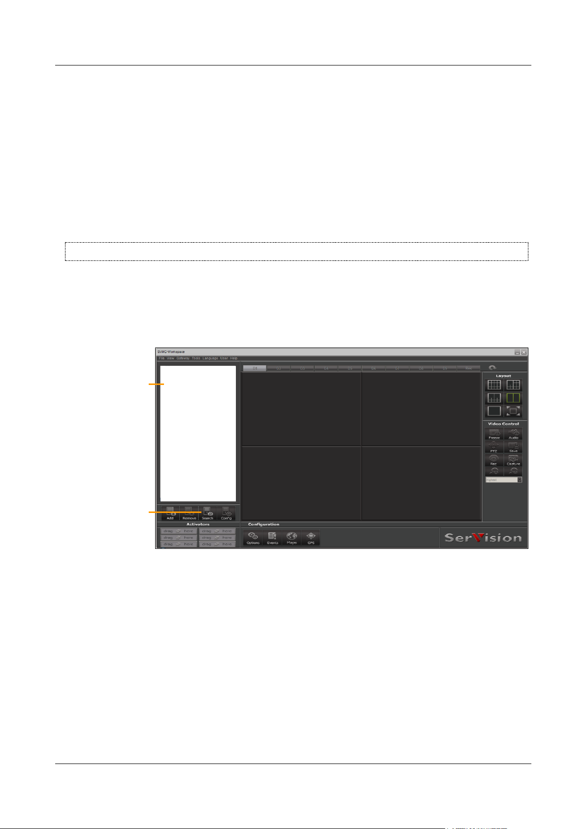
1. Open the SVMultiClient application by double-clicking the desktop icon or by selecting it in the Start menu
(Start>Programs>SerVision>SVMultiClient>SVMultiClient).
2. In SVMultiClient, at the bottom of the Connection Panel, click the Search button.
Figure 3: Search button
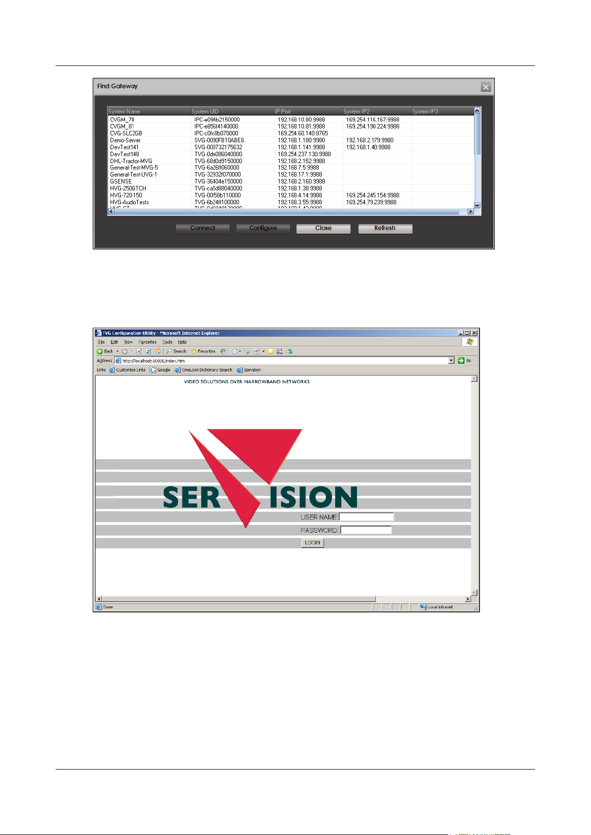
The Find Gateway dialog box opens, and displays a list of all the SerVision systems connected to the
network.
Getting Started 8
SerVision Embedded Video Gateway System Guide
Figure 4: Find Gateway dialog box
Note: It may take a few minutes before the Video Gateway unit appears in the list.
3. Select the Video Gateway and then click Configure. A browser window opens and displays the configuration
Login screen.
Figure 5: Login screen
4. Fill in the User Name and Password fields.
Note: By default, the username is svuser and the password is servconf. Use these values the first time
you log into the configuration utility. Once you have logged in, it is recommended that you change these
values (see Authentication, page 60).
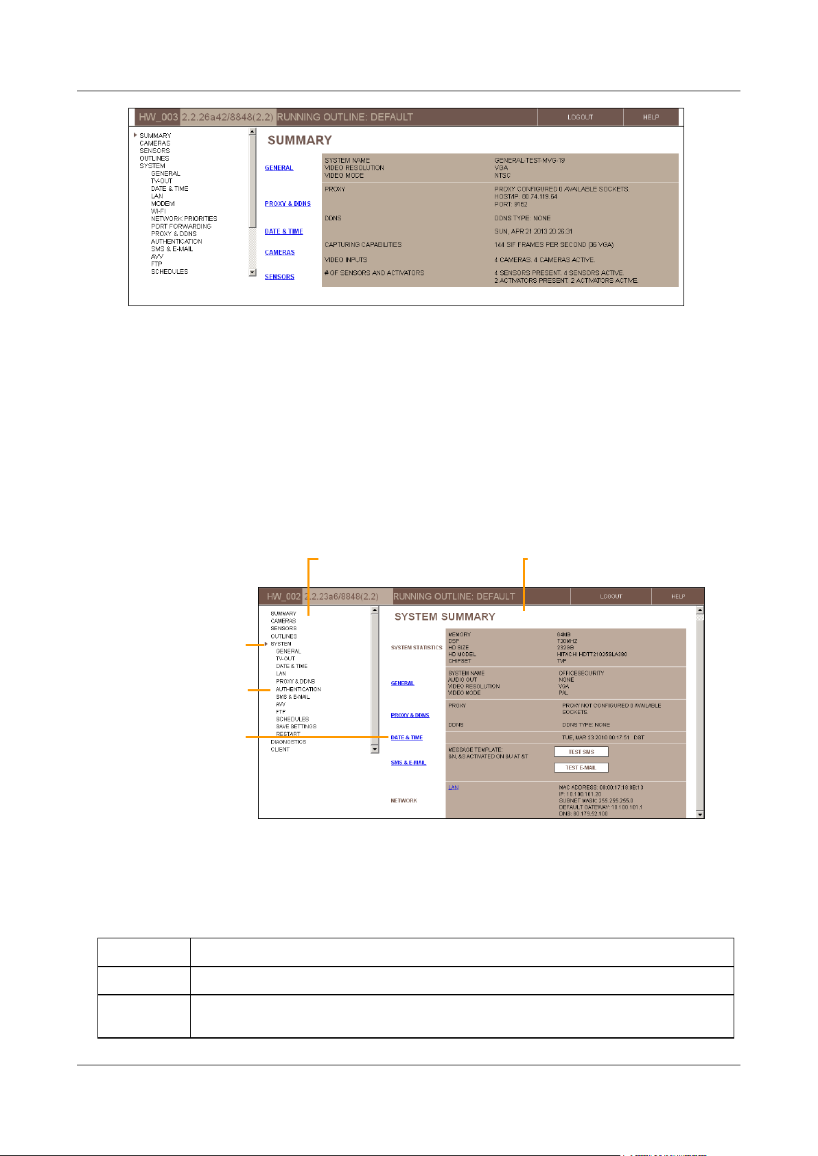
The Summary screen opens:
Getting Started 9
SerVision Embedded Video Gateway System Guide
Summary
Displays a summary of the system's settings and status
Cameras
Configuration of video settings for each camera, including PTZ settings (remote camera control),
VMD (Video Motion Detection), and recording settings
Links to lower-level
screens
Selected top-level
screen
Lower-level option
Main Menu
Screen
Figure 6: Summary screen
Overview of the Interface
The configuration utility consists of screens that are displayed on the right side of the window and a Main Menu in
a sidebar on the left side of the window.
The Main Menu has a hierarchic tree structure. When you select one of the top level options, lower-level options
appear below it in the menu.
Top-level menu options generally open summary screens that display the current settings in a given category and
may include links from which you can access some of the lower-level screens in the selected category. Lower-level
screens are used to modify configuration settings and manage the system.
Figure 7: Elements of the interface
Top-Level Menu Options
The following top-level menu options are available:
Getting Started 10

SerVision Embedded Video Gateway System Guide
Sensors
Configuration of sensors and activators
Outlines
Configuration of sets of different camera and sensor settings that can be activated either
manually or automatically in response to sensor events or according to a fixed schedule
System
Configuration of general system settings, including network settings, unit date and time,
authentication, configuration of SMS and e-mail notifications, and TV-Out settings
Saving configuration changes on the unit and restarting the unit
Diagnostics
Tools for monitoring and testing the system
Client
Viewing lists of events that were detected, selecting events to download to an FTP server,
viewing live snapshots from a camera
Model
Logout
Help
Version
Outline
Status Bar
A status bar at the top of the screen contains the following elements:
Figure 8: Status bar elements
Model: Video Gateway model number
Version: Firmware version
Outline: Name of the current outline (see Defining Alternate Outlines, page 149)
Logout button; click to log out of the configuration utility and display the Login screen again
Help button; click to open the SerVision website in a browser window. The website includes information
about configuring and working with your Video Gateway system, including the most up-to-date version of this
manual (under Support->Documentation->Manuals and Product Overviews)
Using the Configuration Utility
Typically, the configuration process proceeds as follows:
Getting Started 11
SerVision Embedded Video Gateway System Guide
Update confirmation message
Update
To configure a Video Gateway unit:
1. In the Main Menu, click one of the top-level options, e.g., Cameras or Sensors. The selected summary
screen opens.
2. Click an option in the Main Menu or a link in the summary screen to open the desired lower-level screen. The
screen opens.
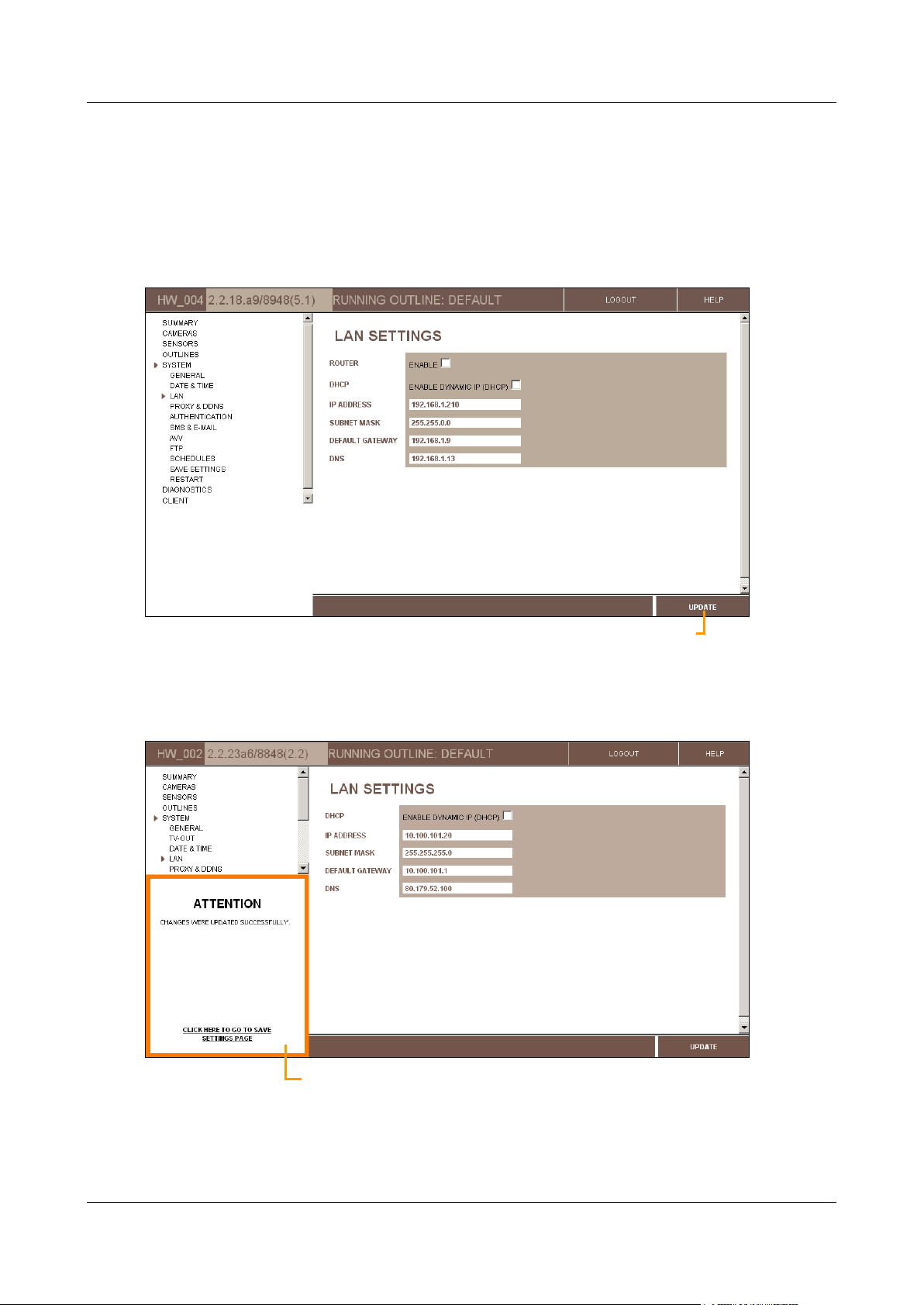
3. Modify the settings in the settings in the screen as necessary, and then click Update to store them on the unit.
Figure 9: Update button
The changes are saved in a temporary cache on the unit, and an Update Confirmation (ATTENTION) message
appears at the lower left of the screen, below the Main Menu.
Figure 10: Update confirmation message
Getting Started 12
SerVision Embedded Video Gateway System Guide
Note: If the update confirmation message does not appear, or an error message appears, all changes made
since the last successful update of the page are discarded.
4. To modify additional settings, navigate to the relevant screen and make the changes as necessary. Click
Update in each screen when you are finished modifying its settings. (You can continue modifying the settings
in the same screen, if necessary; just be sure to click Update before you navigate to a different screen to
ensure the settings are saved as they are displayed.)
5. When you have updated all the settings as necessary, do one of the following:
In the update confirmation message, click “Click here to go to Save Settings page.”
In the Main Menu, under System, click Save Settings.
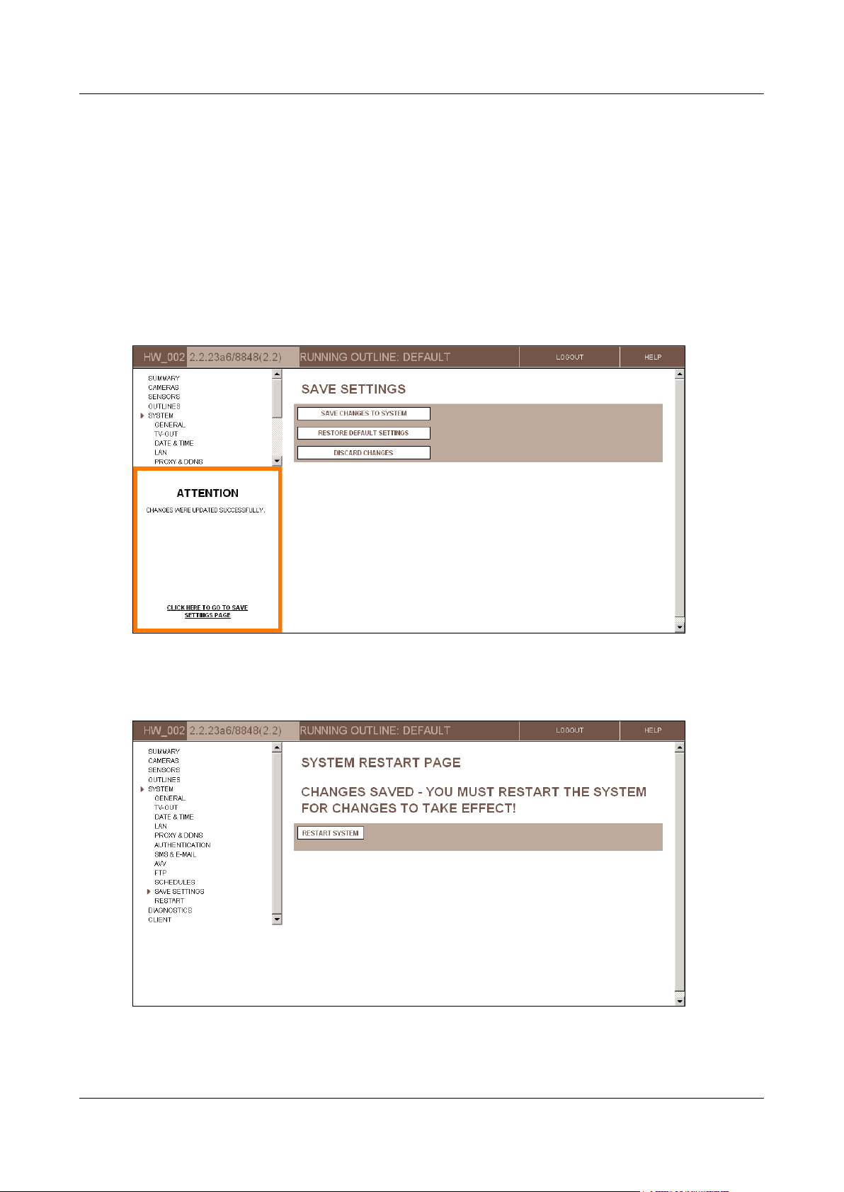
The Save Settings screen opens:
Figure 11: Save Settings screen
6. In the Save Settings screen, click Save Changes to System. The unit stores the changes permanently, and
the System Restart Page screen opens:
Figure 12: System Restart Page screen
Getting Started 13

SerVision Embedded Video Gateway System Guide
7. Click Restart System. The unit restarts, and the changes are implemented. You are automatically logged out
of the configuration utility.
Note: Most changes to the settings in the configuration screens only take effect on the Video Gateway unit
after they are saved and the unit is restarted, as describe in steps 5–7. For additional information, see Saving
Configuration Changes, page 156.
Note: For security reasons, a configuration session times out after 15 minutes. If the configuration utility is
open with no user activity (pages loaded) for more than 15 minutes, you must perform the login procedure
again to continue configuring the Video Gateway unit. Configuration changes that were made during the
timed-out session are not discarded, as long as Update was clicked in the relevant screen before the time-out
occurred.
Opening the Configuration Remotely
Once the unit has been configured for remote client access via the internet (see LAN Settings, page 38), you can also
access the configuration utility remotely via the internet. To do this, all you need is a PC that is connected to the
internet. You can then access the configuration utility in one of the following ways:
Through SVMultiClient: Connect to the Video Gateway and use SVMultiClient to access the configuration
utility, as explained below. (For additional information about working with SVMultiClient, please refer to the
SVMultiClient User Guide.)
Manually through a browser: Enter the address and port in the Address field of a browser window, as
described under Opening the Configuration Manually, page 14.
Both of these methods can also be used to access the configuration utility over the internet through a proxy
connection.
To access the configuration utility remotely through SVMultiClient:
1. Connect to the Video Gateway through SVMultiClient.
Note: SVMultiClient's Search function does not work over the internet. Therefore, you will have to manually
add and configure the connection to the Video Gateway. For information about how to do this, please refer to
the SVMultiClient User Guide.
2. In the Connection Panel (left panel) of SVMultiClient, select the Video Gateway.
3. At the bottom of the Connection Panel, click the Config button. A new browser window opens, and
automatically connects to the configuration utility login page for the Video Gateway.
Note: If you cannot connect remotely through port 10000, the login page will not appear at this point, and the
browser will display an error message instead. Change the port number in the Address field of the browser
from 10000 to the port that is set in the router's port forwarding settings (see General System Settings,
page 17), and press Enter to reload the page. The login page should then appear. For additional information,
see Opening the Configuration Manually, below.
Note: If more than one SerVision Video Gateway is connected to the internet via the same router, each of
them must use a different port. When you click Config in SVMultiClient, the browser automatically connects
to port 10000. As a result, SVMultiClient may initially connect you to the wrong Video Gateway unit. In this
case, you should manually correct the port number in the Address field of the browser, as explained in the
previous note.
Opening the Configuration Manually
The configuration utility can be opened manually in a browser using the IP address and port of the unit. This is
particularly useful in situations in which you cannot open the configuration utility through SVMultiClient. This is
most likely to occur when you are opening the configuration utility remotely and either do not have access to
SVMultiClient or cannot connect to the unit remotely through port 10000.
Getting Started 14
SerVision Embedded Video Gateway System Guide
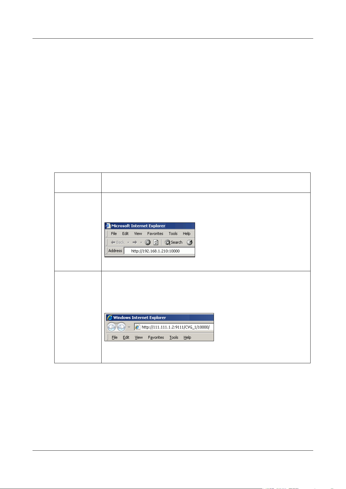
Type
Direct (local or
remote)
http://IP:port
For example, if the Video Gateway’s IP address is 192.168.1.210 and you are
connecting on port 10000, enter http://192.168.1.210:10000, as in figure 13:
Figure 13: Address for configuring a unit with a static IP
Proxy
http://Proxy-IP:Proxy-port/Video Gateway name/Video Gateway
port/
For example, if the proxy server’s IP address is 111.111.1.2, its port number is 9111,
the name of the Video Gateway is CVG_1, and its port is 10000, enter
http://111.111.1.2:9111/CVG_1/10000/, as in figure 13:
Figure 14: Address for configuring a unit via a proxy server
Note: Be sure to include the slash (/) at the end of the address.
To open the configuration utility manually, you must know the network address (IP or hostname) of the Video
Gateway and the port allowing access to the configuration utility. The required network address depends on whether
you are accessing the configuration utility through a local connection (through the same LAN or through an
Ethernet cross cable) or a remote connection (through the internet):
Local connection: The network address is the private IP address of the Video Gateway on the local network.
This can either be its dynamic IP, or, if it has one, its static IP. The port is 10000.
Remote connection: The network address is the public IP or hostname of the router through which the Video
Gateway connects to the internet. The port is the port that allows access to the configuration utility via port
forwarding.
If you connect through a proxy connection, you must also know the network address and port of the proxy server.
To open the configuration utility manually:
1. Open a web browser.
2. In the Address field of the browser, enter the IP address and system port number of the Video Gateway, as
follows:
3. Press Enter. The configuration utility Login screen opens.
4. Log into the configuration utility as usual (see page 9).
Getting Started 15
SerVision Embedded Video Gateway System Guide
Configuring System Settings
System settings include system-wide settings, such as the name of the unit, date and time settings, and network
configuration.
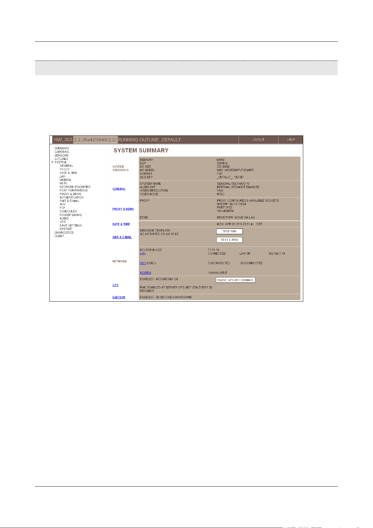
The System Summary screen summarizes the current system settings and provides links to some of the system
configuration screens in which the system settings can be modified. It also includes information about the Video
Gateway unit and the network, and, depending on the configuration settings, may include buttons that you can use
to test the current e-mail and SMS notification settings.
Figure 15: System Summary screen (MVG)
The following system-configuration screens are available:
General: Unit name, port number, and activation of certain options (see page 17)
TV-Out: Configuration of a closed-circuit monitor (CCTV) connected to the Video Gateway (see page 25)
Date & Time: Automatic and manual time setting (see page 33)
LAN: Ethernet network settings (see page 38)
Modem: Cellular modem configuration (UVG400, MVG, and CVG-M only; see page 40)
WiFi: Wireless network connection and access-point settings (UVG400 and MVG only; see page 47)
Network Priorities: Ranking the available network connections for outgoing communication from the unit to
other networks, to indicate which connections should be tried first (UVG400 and MVG; see page 54)
Port Forwarding: Configuring ports that allow external devices to connect to devices within the local
network managed by the Video Gateway’s router (UVG400 and MVG only; see page 55)
Proxy and DDNS: Proxy and DDNS settings (see page 57)
Authentication: Usernames and passwords for accessing and configuring the unit (see page 60)
Configuring System Settings 16
SerVision Embedded Video Gateway System Guide
SMS & E-mail: Event notification settings (see page 61)
AVV: Configuration of automatic uploading of video to an FTP server (see page 67)
FTP: Configuration of manual uploading of video to an FTP server (see page 74)
Schedules: Configuring the unit to automatically switch the running outline at specified times (see page 76)
Power Saving: Configuring sleep-mode (in development, for use with certain control-center applications;
MVG only)
Audio: Configuring microphones and speakers (see page 85)
GPS: Configuring GPS settings (MVG and CVG-M only; see page 88)
Save Settings: Saving configuration changes (see page 156)
Restart: Restarting the unit in order to fully implement configuration changes or improve system performance
(see page 197)
To open the System Summary screen:
In the Main Menu, click System.
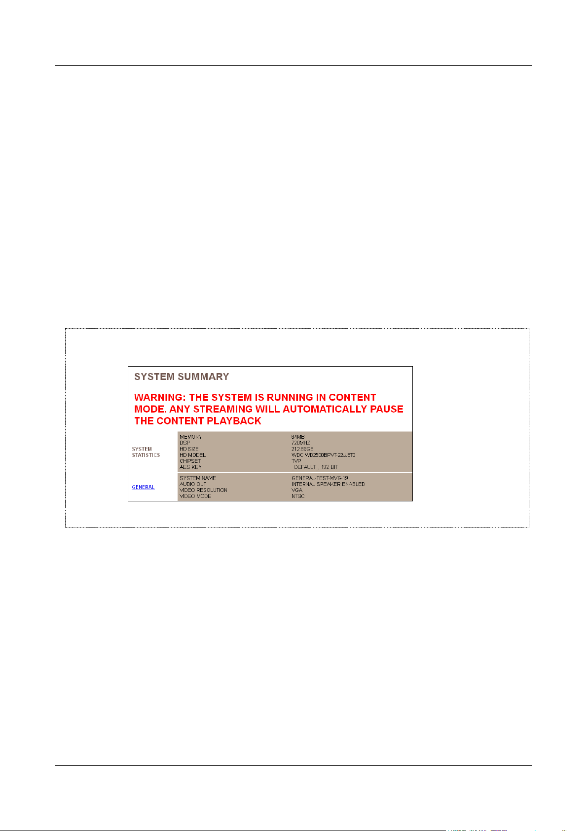
NOTE: If Content mode is enabled in the TV-Out settings, a warning message appears at the top of the System
Summary screen:
For additional information, see Configuring the Monitor to Play Prerecorded Video, page 30.
General System Settings
The general system settings are the basic settings for the unit: the name of the unit, the port it uses for
communication, video resolution and type, and activation of certain optional features.
About the General System Settings
This section contains background information about the general system settings.
Ports
The unit has two access ports:
Port 10000, which is intended for configuration and is always open for incoming connections.
Configuring System Settings 17
SerVision Embedded Video Gateway System Guide
System port, which is intended for client connections, and can be configured. The default number of this port
appears on the sticker on the underside of the unit. (It is usually 9988.) You can configure this port as
necessary to suit the requirements of your network.
NOTE: If port forwarding in your network cannot be set up for port 10000, you can use the system port for
remote configuration as well as client connections.
Video Resolution
The Video Gateway can capture video in one of the following resolutions:
VGA: This resolution is the standard used by digital screens such as computers and cellular phones. When
VGA is selected, the full-screen resolution is 640x480 pixels. Available smaller screen sizes are SIF (one
quarter of full screen; 320x240 pixels) and QSIF (one sixteenth of full screen; 160x120 pixels).
D1: This resolution is the standard used by analog screens such as televisions. When D1 is selected, full-
screen resolution is 704×480 pixels for NTSC systems and 704x576 pixels for PAL systems. Available
smaller screen sizes are CIF (one quarter of full screen; 352x240 pixels for NTSC systems and 352x288 pixels
for PAL systems) and QCIF (one sixteenth of full screen; 176x120 pixels for NTSC systems and 176x144 for
PAL systems).
VGA normally displays properly even on analog equipment such as CCTV screens. If your system supports both
resolutions, it is recommended that you select VGA resolution because it requires slightly less system resources.
Ignition-Off Shut-Down
The Ignition settings define whether the MVG or CVG-M unit should automatically shut down when the vehicle
ignition is turned off and, if so, how long the unit should continue operating after the ignition is turned off before it
shuts down.
Download Optimizations
Downloading recorded video uses system resources that would otherwise be available for other functions such as
recording or streaming live video. Download optimization settings are used to tweak the allocation of system
resources between downloading and other system processes.
These optimization settings are most important for mobile Video Gateways, which may be subject to vastly
different network conditions at different times. For example, if a bus is on the road, it typically only has access to a
cellular connection, which has very limited bandwidth, but when it is the bus yard, it probably also has access to a
high-speed WiFi network. In this case, downloading of the recorded video can be scheduled for times when the bus
is in the yards. Since recording video is only necessary when the bus is on the road, it is best to suspend recording
while downloading is being performed, because this speeds up the downloading process.
The following download-optimization options can be selected:
Enabled: Prevents the unit from initiating transmission of a new stream of recorded video to a client device,
and from beginning to download live or recorded video to a client device, when video is already being
downloaded from the unit. Live streams can be initiated, and all processes that are already in progress
(streaming of live or recorded video to a client or to a connected CCTV monitor, and downloading of video)
continue uninterrupted, unless one or more of the download-optimization options described below are
selected.
Stop Recording on Download: In addition to the above, stops all video recording on the unit when video is
being downloaded from the Video Gateway. This option increases the download speed, because it allocates
more of the unit’s resources to the download task. However, it also means that there may be gaps in the
recorded video at the times that the video is downloaded.
Configuring System Settings 18

SerVision Embedded Video Gateway System Guide
Close All Tasks on Download: Prevents the unit from performing any other jobs – accepting new
connections, streaming live or recorded video, recording video, or downloading other video – when
downloading is in progress.
Block New Connections while Downloading: Prevents the unit from accepting any new connections from
clients while downloading of recorded video is taking place. When this option is selected, transmission of new
live or recorded video streams to client applications does not begin while downloading is underway, but
existing streams are not closed. When this option is not selected, the process of downloading may take
somewhat longer to be completed. In addition, the framerate of video displayed in the client may be reduced at
times while the download is in progress.
Disable TV-Out While Downloading: If a CCTV monitor is connected to the Video Gateway, stops
streaming of video to the monitor while downloading of recorded video is taking place
Additional System Settings
A number of other system settings can be configured in the General System Settings screen:
Video Authentication: Adds a digital signature to each frame of video captured by the system. This signature
makes it possible to identify frames that have been tampered with. When a SerVision client application plays
video that has a digital signature and discovers a frame that has been changed from its original state, the status
of the stream indicates that the stream was modified. (Note: Only the current versions of SVMultiClient and
the Player support this feature.)
Outline Switching: Defines whether the system can activate different outlines automatically and, if so, what
type of trigger will cause the system to switch to a different outline, sensor events (from Sensor 1) or a
schedule. If neither type of automatic outline switching is selected, you can manually change the active outline
at any time. For additional information, see Defining Alternate Outlines, page 149.
Network Speed Optimization: Activates zero-latency handling of video packets. Activating this option may
increase the transmission speed of video from the Video Gateway to client PCs that are on the same LAN as
the Video Gateway. This feature is not recommended for use with other types of client connections (internet,
cellular, etc.). In addition, it is only recommended for use if video transmission speed is problematic. It usually
has a more marked effect on video streaming than on video downloading.
Network TCP Optimization: Opens all sockets with TCP_NODELAY activated. Activating this option may
increase the transmission speed of video from the Video Gateway to client PCs that are on external networks –
internet, cellular, etc. This feature is not recommended for use with clients that are on the same LAN as the
Video Gateway. In addition, it is only recommended if video transmission speed is problematic. It usually has
a more marked effect on video streaming than on video downloading.
SMS on System Start: Sends SMS notifications to all SMS recipients whenever the Video Gateway starts
running. For information about defining SMS recipients, see SMS and E-mail Notifications, page 61.
ADAM Sensors: Enables the activation of sensors that are connected to the Video Gateway unit through an
ADAM module. For additional information, see Configuring Sensor and Activator Settings, page 119.
IA Sensors and Activators: Enables the activation of sensors and activators that are connected to the Video
Gateway unit through an IA 3126-2 relay board. For additional information, please refer to your unit’s
installation manual.
Maximum Recording Length: Automatically erases recorded video after a specified period of time.
Publish System Name: Sends the name and IP address of the Video Gateway to the ARP system of the local
network so that the ARP system can translate the name of the Video Gateway to its IP address. This enables
local users to access the Video Gateway using its name.
Ignore VGA in RT: Tells the Video Gateway not to send VGA video streams (of live or recorded video) to
client applications; when a client requests a VGA stream, the stream is sent in a lower-resolution, although the
VGA image size is retained. Activating this option enhances the stability of the stream when bandwidth is
limited, such as when the Video Gateway transmits video streams over a cellular connection. This option does
not affect video downloading; video can be downloaded in full VGA resolution even if this option is selected.
Configuring System Settings 19

SerVision Embedded Video Gateway System Guide
Real Time Bitrate Control: Tells the Video Gateway to monitor the video transmission, identify situations in
which packets are not being transmitted quickly enough because of bandwidth limitations, and automatically
modify the bitrate of the video to suit the available bandwidth. Activating this option enhances the stability
and quality of the stream when bandwidth is limited, such as when the Video Gateway transmits video streams
over a cellular connection. This option does not affect video downloading; video can be downloaded in full
VGA resolution even if this option is selected.
Time Stamp on Snapshot: Imprints a timestamp indicating when the picture was taken before downloading a
snapshot to a client.
Allow Only Encrypted: Tells the Video Gateway to encrypt all video data before transmitting it. When this
option is selected, clients cannot connect to the Video Gateway unless AES encryption is turned on in the
client application.
Note: If clients connect to the Video Gateway through a proxy server, when this option is selected, the video
data is transmitted from the Video Gateway to the proxy server in encrypted form. If you want it to be
encrypted when it is transmitted from the proxy server to clients, you must select Encrypt Proxy
Communication in the Proxy and DDNS Settings screen. For additional information, see Proxy and DDNS
Settings, page 57.
Note: For information about AES encryption, see Modifying the AES Key, page 192.
Event on Ignition: Generates an Ignition event whenever the vehicle ignition is turned on.
Maximum Allowed Streams: By default, the Video Gateway can transmit up to 20 video streams at one time.
This option can be used to further limit the number of simultaneous video streams that can be transmitted. This
may be useful, for example, if the local network to which the Video Gateway is connected cannot support so
many video streams at one time. If the maximum number of streams has been reached, clients requesting
additional streams from the Video Gateway receive an error message saying "Stream not available."
Configuring System Settings 20
SerVision Embedded Video Gateway System Guide
System Name
Assign a name to the Video Gateway unit (up to 20 Unicode (UTF-8) characters).
This name is used to identify the unit in client applications such as SVMultiClient, in
SMS and e-mail notifications, in AVV file names, and on the proxy.
Note: Spaces and underscores in the name may cause problems with various
network functions, such as e-mail notifications, proxy, and DDNS. Therefore, it is
recommended not to include any spaces or underscores in the name.
System Port
Fill in the client access port of the Video Gateway unit.
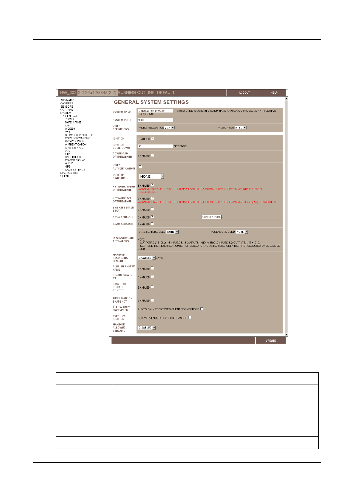
Configuring General System Settings
To adjust the general system settings:
1. In the Main Menu, under System, click General. The General System Settings screen opens:
Figure 16: General System Settings screen (MVG)
2. Fill in the fields as follows:
Configuring System Settings 21

SerVision Embedded Video Gateway System Guide
Note: If you want to access the unit remotely and cannot set up port forwarding
for port 10000 in your network, you can also access the configuration utility using
this port.
Video Resolution
Select the video resolution (VGA or D1). VGA is recommended for most applications.
Note: If you change the video resolution, all recorded video is erased from the unit.
Video Mode
Select the video format (PAL or NTSC) used by the camera.
Note: NTSC is generally used in North America. PAL is standard in most other
locations. For additional information, consult the camera documentation.
Note: If you are connecting a CCTV monitor to the Video Gateway, ensure that the
monitor supports the video mode selected here. Some SECAM monitors will also
work when the PAL video mode is selected.
Note: When D1 video resolution is selected, and you change the video mode, all
recorded video is erased from the unit.
Ignition
(MVG and CVG-M
only)
Select this option if you want the unit to power down automatically whenever the
ignition is turned off. If you do not select this option, the unit operates continuously
as long as it has a power supply.
Note: This setting only affects the unit if the unit is connected both directly to the
battery and to the ignition. Otherwise, the unit operates continuously as long as it
has a power supply. (For additional information, please refer to the unit’s
installation guide.)
Ignition Countdown
(MVG and CVG-M
only)
Select the amount of time that the unit should continue operating after the vehicle
ignition is turned off, in seconds.
Note: This setting only affects the unit if the unit is connected both directly to the
battery and to the ignition. Otherwise, the unit operates continuously as long as it
has a power supply. (For additional information, please refer to the unit’s
installation guide.)
Note: This field only appears if the Ignition checkbox is selected.
Download
Optimizations
Select this option if you want to activate any of the download optimization settings.
If this option is selected, while downloading is in progress the Video Gateway will fill
new requests from clients for live-video streaming, but it will not fill new requests
for playback of recorded video or for downloading of other video.
When this checkbox is selected, additional fields are added to the screen; these
fields allow you to further configure the download-optimization settings, as
explained below. For additional information, see
Download Optimizations
, page 18.
Stop Recording on
Download
Select this option to stop all video recording when video is being downloaded from
the Video Gateway.
Note: This field only appears if Download Optimizations is enabled.
Close All Tasks on
Download
Select this option to stop all other actions – accepting new connections from clients,
streaming live or recorded video, recording video, and other downloading jobs –
when downloading is in progress.
Note: This field only appears if Download Optimizations is enabled.
Block New
Connections while
Downloading
Select this option to prevent the streaming of new live or recorded video streams to
a client application while downloading of recorded video to a PC is taking place.
Note: This field only appears if Download Optimizations is enabled.
Configuring System Settings 22

SerVision Embedded Video Gateway System Guide
Disable TV-Out while
Downloading
Select this option to stop streaming to the CCTV monitor connected to the Video
Gateway while downloading of recorded video to a PC is taking place.
Note: This field only appears if Download Optimizations is enabled and if TVOut is enabled (see
Configuring a CCTV Monitor (TV-Out)
, page 25).
Video Authentication
Select this option if you want the system to include a digital signature in each video
frame streamed and/or recorded by the unit. The signature can be used to identify
streams that were tampered with.
Note: This option increases the load on the system resources slightly, so it is
advisable to activate it only if it is truly required.
Outline Switching
Select one of the following types of triggers for activating different outlines:
None: No automatic outline switching – outlines can only be
switched manually using the configuration utility (see
Defining
Alternate Outlines, page 149)
Sensor: Makes it possible to use Sensor 1 events as triggers for
outline switching (see
Configuring Sensor and Activator
Settings,
page 119)
Note: For CVG and CVG-M models, this option should not be selected if
the sensor connector (In1) is used to control the display on a connected
CCTV monitor. For additional information, please refer to the unit’s
installation guide.
Schedule: Makes it possible to schedule outline switching (see
Schedules
, page 76)
Network Speed
Optimization
If video from the unit will be viewed primarily or exclusively on PCs that are on the
same LAN as the unit, select this option to minimize the streaming delay within the
LAN. That is, when this option is selected, live video will be played as close to real
time as possible.
Clear this option if live video will be viewed remotely via the internet or a modem
connection.
Network TCP
Optimization
If video from the unit will be transmitted primarily or exclusively to client devices
that are
not
on the same LAN as the unit, select this option to minimize the
streaming delay. That is, when this option is selected, live video will be played as
close to real time as possible.
Clear this option if live video will be viewed primarily on devices that are on the
same LAN as the Video Gateway.
SMS on System Start
Select this option if you want the unit to send SMS notifications whenever it starts
running.
SBox Sensors
(MVG and CVG-M
only)
[Not currenty in use.]
ADAM Sensors
If sensors are connected to the unit through an ADAM module, select Enabled.
This makes it possible to activate and configure the sensors. For additional
information, see
Configuring Sensor and Activator
Settings, page 119.
IA Activators Used
If activators are connected to the unit through an IA relay board, select the number
of activators that are connected to the board. For additional information, please
refer to the unit’s installation guide.
Configuring System Settings 23

SerVision Embedded Video Gateway System Guide
IA Sensors Used
If sensors are connected to the unit through an IA relay board, select the number
of sensors that are connected to the board. For additional information, please refer
to the unit’s installation guide.
Maximum Recording
Length
If you want recorded video to be erased automatically after a specified period of
time, select the desired time period. A day is defined by the system as beginning at
midnight. For example, if you select “1,” the system saves all video that was
recorded from midnight yesterday on. Video that was recorded before midnight
yesterday is automatically erased.
Note: When video is erased in this way, the storage space it occupied on the unit’s
storage media is not made available for additional recordings.
Publish System
Name
Select this option if you want the name of the Video Gateway to be recognized on
the LAN to which the Video Gateway is connected. When this option is selected,
users on the LAN can connect to the Video Gateway using either its name or its
local IP address. When this option is not selected, only the IP is recognized in the
LAN.
Ignore VGA in RT
Select this option to prevent the Video Gateway from streaming video in VGA
resolution. When this option is selected, the Video Gateway sends clients video
streams in SIF resolution when they request VGA. This option should be selected
when the Video Gateway is streaming video via a low-bandwidth connection such as
a cellular connection.
Real-Time Bitrate
Control
Select this option to allow the Video Gateway to automatically modulate the bitrate
of video streams to suit the available bandwidth of the connection.
Timestamp on
Snapshot
Select this option to include a timestamp in all snapshots that are saved from video
streams.
Allow Only
Encrypted
Select this option to transmit all video to clients in encrypted form, by preventing
clients from connecting to the Video Gateway if they are not using AES encryption.
Note: The client essentially controls whether the Video Gateway transmits video to
it in encrypted form or not; the Video Gateway transmits encrypted video whenever
the client requests it.
Note: For information about encrypting video that is transmitted to a proxy server,
see
Proxy and DDNS Settings
, page 57.
Event on Ignition
(MVG and CVG-M
only)
Select this option if you want an event to be generated by the system whenever the
ignition of the vehicle is turned on.
Maximum Allowed
Streams
By default (when Disabled is selected), the Video Gateway can transmit up to 20
video streams simultaneously. To further limit the number of simultaneous streams,
select the maximum number of simultaneous streams. (You can choose values
between 1 and 10.) Reducing the number of simultaneous streams may improve
stream stability and quality when the video is transmitted over low-bandwidth
networks such as cellular networks.
3. Click Update, and then save the settings. They will be implemented after the unit is restarted (see Saving
Configuration Changes, page 156).
Configuring System Settings 24
SerVision Embedded Video Gateway System Guide
Configuring a CCTV Monitor (TV-Out)
If a video monitor is connected to your Video Gateway, you must activate and configure it before you can see video
on it. The monitor can be used for one of two purposes: to view video from the Video Gateway, or to play
prerecorded video content that is stored on the unit, such as movies or ads.
NOTE: For information about setting up a CCTV monitor, please refer to your unit’s installation guide.
NOTE: TV-Out makes use of the same system resources as the unit’s video recorder. As a result, the global
framerate available for recording is reduced somewhat when TV-Out is enabled. For additional
information about recorder framerates, see Advanced Recorder Settings, page 106.
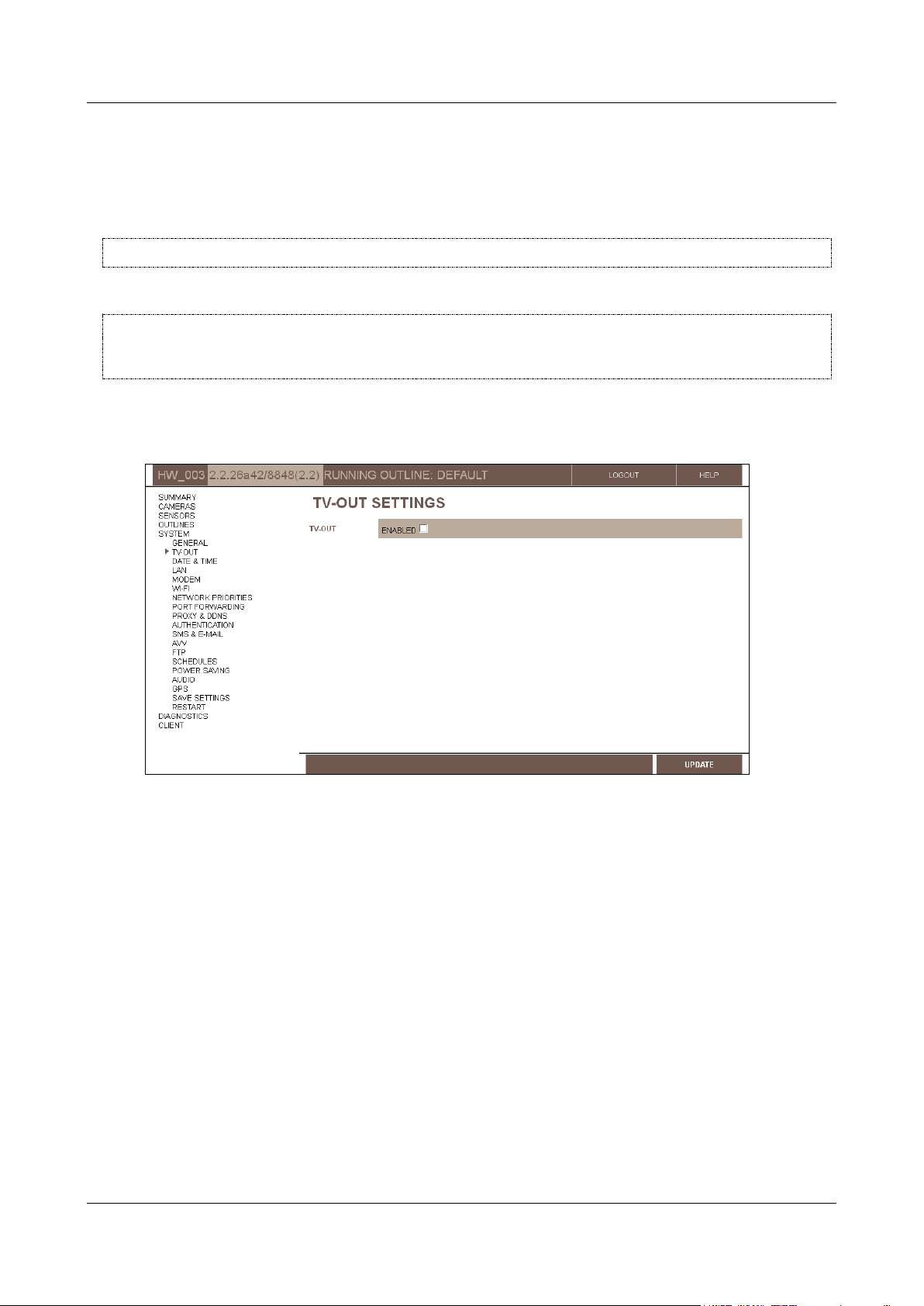
To enable a CCTV monitor connected to the Video Gateway unit:
1. In the Main Menu, under System, click TV-Out. The TV-Out Settings screen opens:
Figure 17: TV-Out Settings screen
2. Select Enabled. The fields required to configure the monitor display are added to the screen.
Configuring System Settings 25
SerVision Embedded Video Gateway System Guide
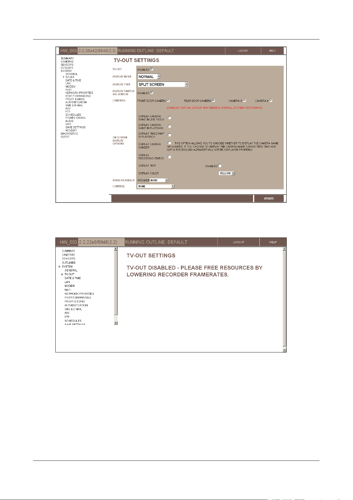
Figure 18: TV-Out settings displayed (MVG)
Note: TV-Out cannot be enabled if recording framerates are very high (see Advanced Recorder Settings,
page 106). In this case, if you attempt to enable TV-Out, a TV-Out Disabled message will be displayed:
Figure 19: TV-Out Disabled message
3. Configure the monitor as explained in the next sections (Configuring the Monitor to Display Video from the
Video Gateway, below, and Configuring the Monitor to Play Prerecorded Video, page 30).
Configuring the Monitor to Display Video from the Video Gateway
A CCTV monitor connected to the Video Gateway unit can be used to display live video from the unit in various
ways, as configured in the TV-Out Settings screen. If the monitor has a touch screen, or the supplied mouse is
connected to the unit, the display can be changed on the fly and recorded video can be played back.
Configuring System Settings 26
SerVision Embedded Video Gateway System Guide
Field
Description
Display type
Select the desired layout for the video display on the monitor:
Split Screen: Divides the screen so that video from all the
cameras is visible all the time
Full Screen – Camera #: Displays video from the specified
camera in full-screen mode
No Display: Does not display any live video; instead, only a menu
is displayed. The display can be controlled from the menu (if the
monitor has a touch screen or a mouse is connected to it).
Full Screen – Rotate: Loops through all of the cameras,
displaying each in full-screen mode for the number of seconds
specified under Rotate delay
Rotate delay
If you selected the Full Screen – Rotate display type, specify the number of
seconds you want the video from each camera to be displayed before it is replaced
with video from the next camera.
Note: This field only appears if the Full Screen – Rotate display type is selected.
NOTE: For information about viewing video from the Video Gateway unit on a connected CCTV monitor, see
Appendix A: Viewing Video on a CCTV Monitor (TV-Out), page 207.
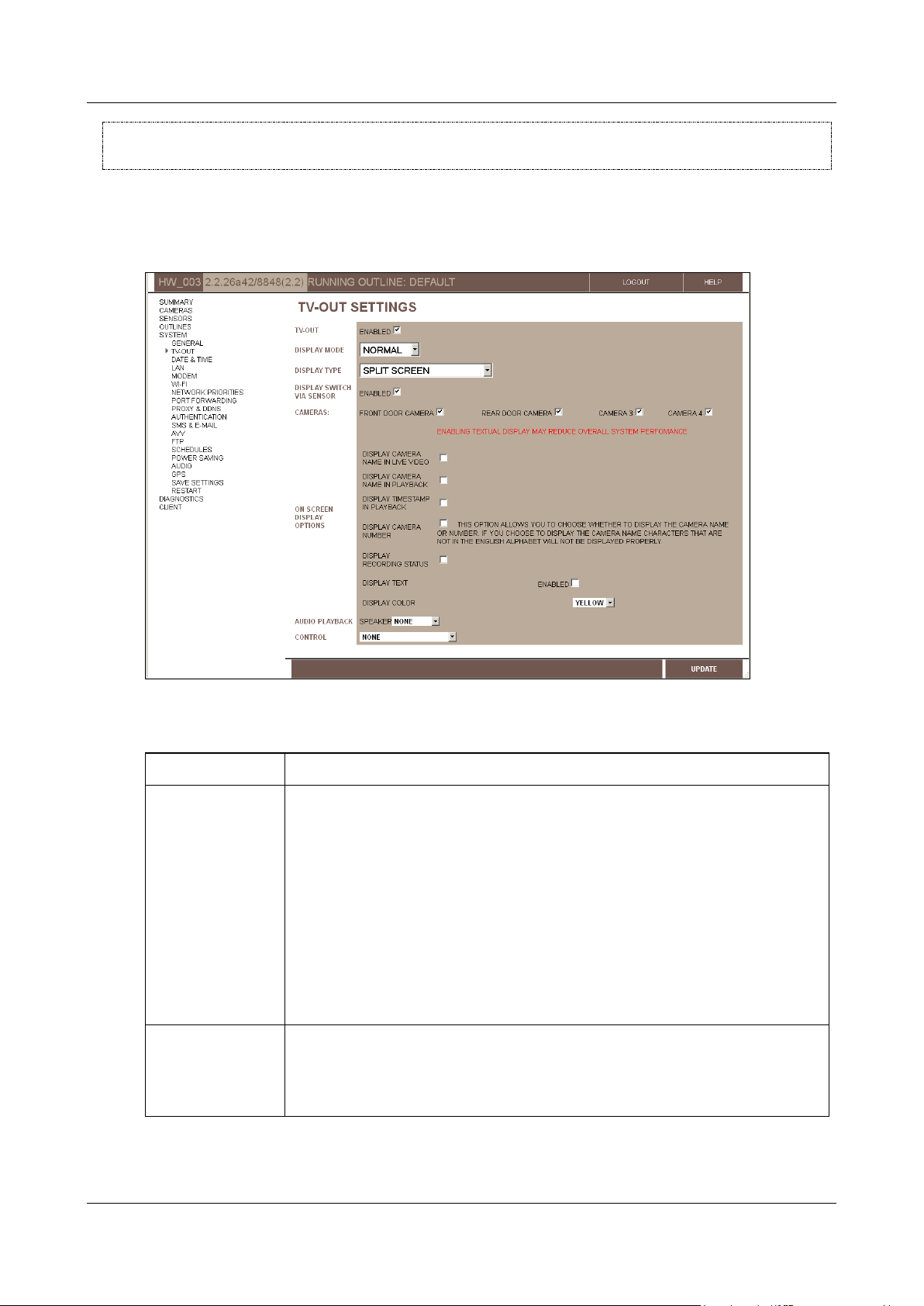
To configure the CCTV monitor to display video from the Video Gateway:
1. In the TV-Out Settings screen, under Display Mode, select Normal. The fields required to configure the
monitor to display video from the Video Gateway are added to the screen:
Figure 20: TV-Out settings for Normal display (MVG)
2. Fill in the fields as follows:
Configuring System Settings 27

SerVision Embedded Video Gateway System Guide
Field
Description
Display Switch Via
Sensor
Select this option if a switch is connected to the relevant sensor connector on the
unit (In6 on the HVG400; In4 on the MVG400, and UVG400; In1 on MVG200, CVG,
and CVG-M models), and you want to use the switch to cycle through the various
display types.
Note: This option is only fully activated if it is selected here and configured in the
appropriate sensor configuration screen (for HVG400, MVG400, or UVG400, the
Sensor 4 configuration screen; for MVG200, CVG, or CVG-M, the Sensor
configuration screen), as described under
Configuring a Sensor to Control CCTV
Display
, page 126.
Note: On MVG200, CVG and CVG-M models, this option should not be selected if the
sensor connector (In1) is used for an outline switch. For additional information,
please refer to the unit’s installation guide.
Cameras
Select the cameras that will be accessible via the monitor. Cameras that are not
selected do not appear in the monitor at all. Video from these cameras cannot be
viewed on the monitor and the cameras cannot be configured through the monitor.
Display Camera
Name in Live Video
Select this option if you want the name of the camera to be displayed in the camera
pane when live video is played on the monitor.
Note: Displaying names on the monitor requires extra system resources and may
impede performance.
Note: If the name of a camera contains characters from non-Latin alphabets such as
Hebrew or Arabic, or accented characters, those characters are not displayed
properly on the monitor. In this case, you can select both this option and Display
Camera Number (see below) in order to display the index of the camera (1, 2, 3,
or 4) instead of its name.
Display Camera
Name in Playback
Select this option if you want the name of the camera to be displayed in the camera
pane when recorded video is played on the monitor.
Note: Displaying names on the monitor requires extra system resources and may
impede performance.
Note: Recorded video can only be played on the monitor if touch or mouse support
is enabled (see step 6 below). Otherwise, this option has no effect.
Note: If the name of a camera contains characters from non-Latin alphabets such as
Hebrew or Arabic, or accented characters, those characters are not displayed
properly on the monitor. In this case, you can select both this option and Display
Camera Number (see below) in order to display the index of the camera (1, 2, 3,
or 4) instead of its name.
Display Timestamp
in Playback
Select this option if you want the date and time to be displayed in the camera pane
when recorded video is played on the monitor.
Note: Displaying timestamps on the monitor requires extra system resources and
may impede performance.
Note: Recorded video can only be played on the monitor if touch or mouse support
is enabled (see step 6 below). Otherwise, this option has no effect.
Display Camera
Number
If you chose to display the camera name for live and/or recorded video, select this
option to display the camera number instead of its name. This is particularly useful if
the name contains non-Latin characters that are not displayed properly on the
monitor.
Note: This option has no effect if neither Display Camera Name in Live Video
nor Display Camera Name in Playback is selected.
Configuring System Settings 28
SerVision Embedded Video Gateway System Guide
Field
Description
Display Recording
Status
Select this option if you want the recording status to be displayed at the bottom of
the screen at all times. The recording status indicates whether recording is taking
place as it should be, and, if it is, displays the current recording status of each
camera in the system. For additional information, see
Recording Status Display
,
page 235.
Text field
Hexadecimal
code field
Test Color
button
3. If you want any other text to be displayed on the monitor, such as your company name or an advertisement,
under Display Text, select Enabled. A text field is added to the screen. Enter the text you want to display in
the text field. The text will be displayed on the monitor at the bottom of the screen, in the center.
Figure 21: Text field
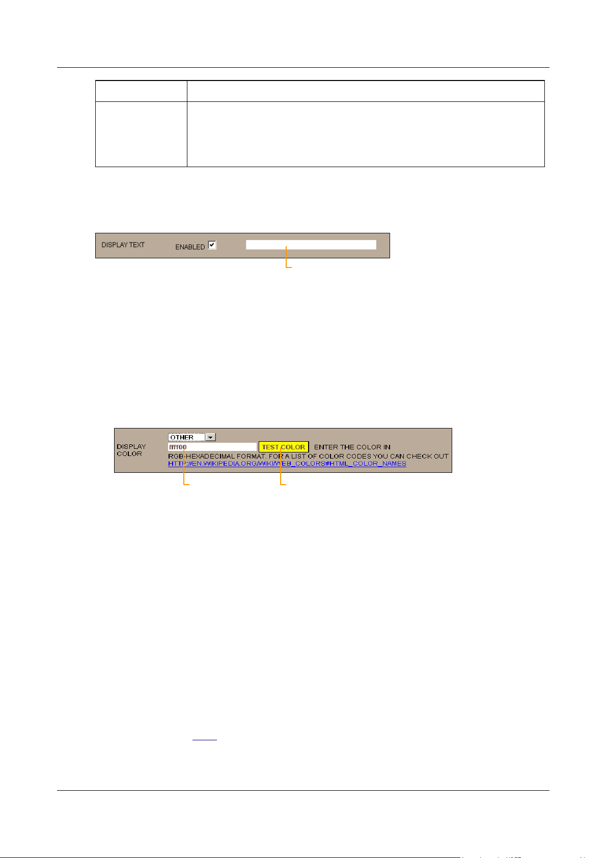
4. Under Display Color, select the color in which on-screen text should be displayed. You can choose one of
five preset colors or select any color you wish by specifying its RGB hexadecimal code, as follows:
To select one of the preset colors: from the dropdown list, select Yellow, Orange, Black, Blue, or Red.
To specify a hexadecimal code: from the dropdown list, select Other. The fields required to specify the
color are added to the screen. The hexadecimal code field displays the hexadecimal code of the currently
selected color. The code consists of three two-digit hexadecimal numbers, for the red, green, and blue
components of the color, respectively. The current color is displayed as the background to the Test Color
button.
Figure 22: Hexadecimal number field
Type the desired hexadecimal code into the field. To see what the color looks like, click Test Color.
Note: For more information about RGB hexadecimal codes, click the link below the fields.
5. Under Speaker, select one of the following audio playback options (for playback of recorded video):
None: Do not play attached audio when recorded video is played.
Internal: Play attached audio from the unit’s built-in internal speaker when recorded video is played.
External: Play attached audio from the external speaker plugged into Aout when recorded video is
played.
Note: This option only effects playback of recorded video streams that have audio attached (i.e., a microphone
attached to the Video Gateway is linked to the camera recording the video stream).
6. Under Control, select one of the following options:
None: Users cannot control the monitor display; video will be displayed in accordance with the selected
Display Type (see above). This option should be chosen if the monitor does not have a touchscreen, and a
mouse is not connected to the Video Gateway. You can also use it to disable the touch feature of a
touchscreen or to disable a connected mouse.
Configuring System Settings 29
 Loading...