

SerVision IVG400-N Quick Start Manual
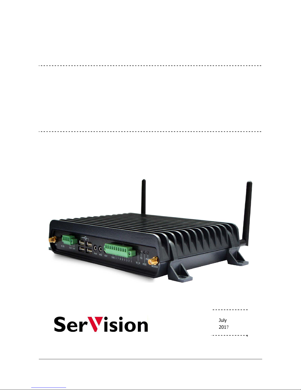
IVG400-N
Quick-Start Guide
July
2017

SerVision IVG400-N Quick-Start Guide
1
Trademarks & Copyright
Trademarks
All trademarks mentioned in this manual are the sole property of their respective manufacturers.
Copyright
SerVision Ltd., Jerusalem, Israel
www.servision.net • info@servision.net
© 2017 SerVision Ltd. All rights reserved.
Notice
Information in this document is subject to change without notice. SerVision Ltd. assumes no responsibility for any
errors that may appear in this manual. Companies, names and data used in examples herein are fictitious unless
otherwise noted. No part of this document may be copied or reproduced in any form, or by any means, electronic or
mechanical, for any purpose, without the express written permission of SerVision Ltd. SerVision Ltd. makes no
warranties with respect to this documentation and disclaims any implied warranties of merchantability or fitness for
a particular purpose.
IVG400-N sw v 0.1.53
SVCentral v 3.7.8.3
Doc v 1.4

SerVision IVG400-N Quick-Start Guide
2
Table of Contents
Introduction 3
The IVG400-N Package 3
Peripheral Equipment 4
Diagrams of Connectors 5
Front Panel 5
Rear Panel 5
Installing the IVG400-N Unit 6
Mounting the Unit 6
Installation in a Vehicle 7
Connecting the Unit to a Vehicle Battery 7
Connecting the Cameras 8
Connecting the Unit to External Networks 8
Installing the GPS Antenna 10
Starting the IVG400-N 10
Opening WebMax 10
Connecting to WebMax through an HDMI Monitor 10
Connecting to WebMax from a PC 11
Overview of SVCentral 11
Connecting a PC to the IVG400-N Unit 12
Opening WebMax from SVCentral 15
Configuring the IVG400-N 16
Logging into WebMax 16
Overview of the WebMax Interface 17
Modifying Settings 17
Setting the Time 19
Setting Up WiFi Connectivity 19
Setting Up Cellular Connectivity 20
Enabling GPS Tracking 20
Viewing Video from the IVG400-N in SVCentral 21
Shutting the IVG400-N Down 21
SerVision IVG400-N Quick-Start Guide
Introduction
This guide briefly explains how to set up the hardware components and perform a preliminary configuration of
SerVision’s IVG400-N security system. The IVG400-N is the newest addition to SerVision’s family of Video
Gateway units. Video Gateway units provide state-of-the-art security functionality, including live video streaming,
video recording and playback, motion detection, sensor management, real-time event notification, and device
activation. All of these features can be accessed remotely via PC, cellular telephone, or tablet. The IVG400-N is the
first Video Gateway to support IP cameras, and it can handle video-frame resolutions up to full HD.
The IVG400-N is suitable for deployment in a variety of environments, from offices and homes to remote locations
and moving platforms. It has built-in support for cable-based, WiFi, and cellular networking, and contains an
internal GPS receiver that makes it possible to track the location and route of a vehicle in which it is installed.
Configuration of the IVG400-N is performed in the unit’s configuration utility, WebMax, which can be accessed
either by means of an HDMI monitor connected to the unit, or from a browser on a PC. Basic instructions for
configuring the IVG400-N are included in this guide.
Client software is used for accessing the IVG400-N unit remotely in order to view video and events and control the
system in various ways. SerVision’s next-generation client application for PCs, SVCentral, offers a full range or
features for viewing and working with digital video streams created by the IVG400-N. A brief overview of
SVCentral is included in this guide. Client software for Android and iOS devices such as smart phones and tablets
are also available.
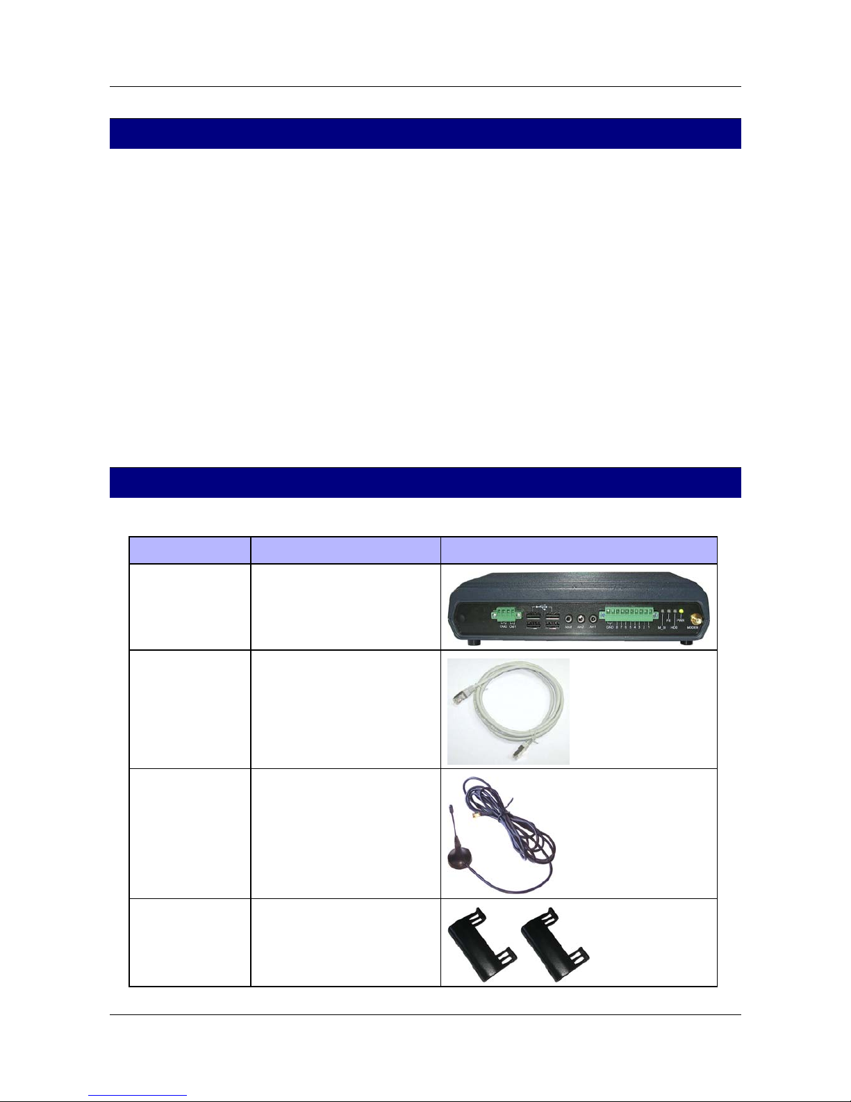
The IVG400-N Package
The IVG400-N package contains the following items:
Item Description Illustration
IVG400-N unit Video Gateway
Ethernet (LAN)
cable
Connects the unit to a PC or a
local network
Cellular-modem
antenna
Enables the built-in cellular
modem to connect to cellular
networks
2 supports Used to install the unit in a
vehicle or on a wall
Introduction 3
SerVision IVG400-N Quick-Start Guide
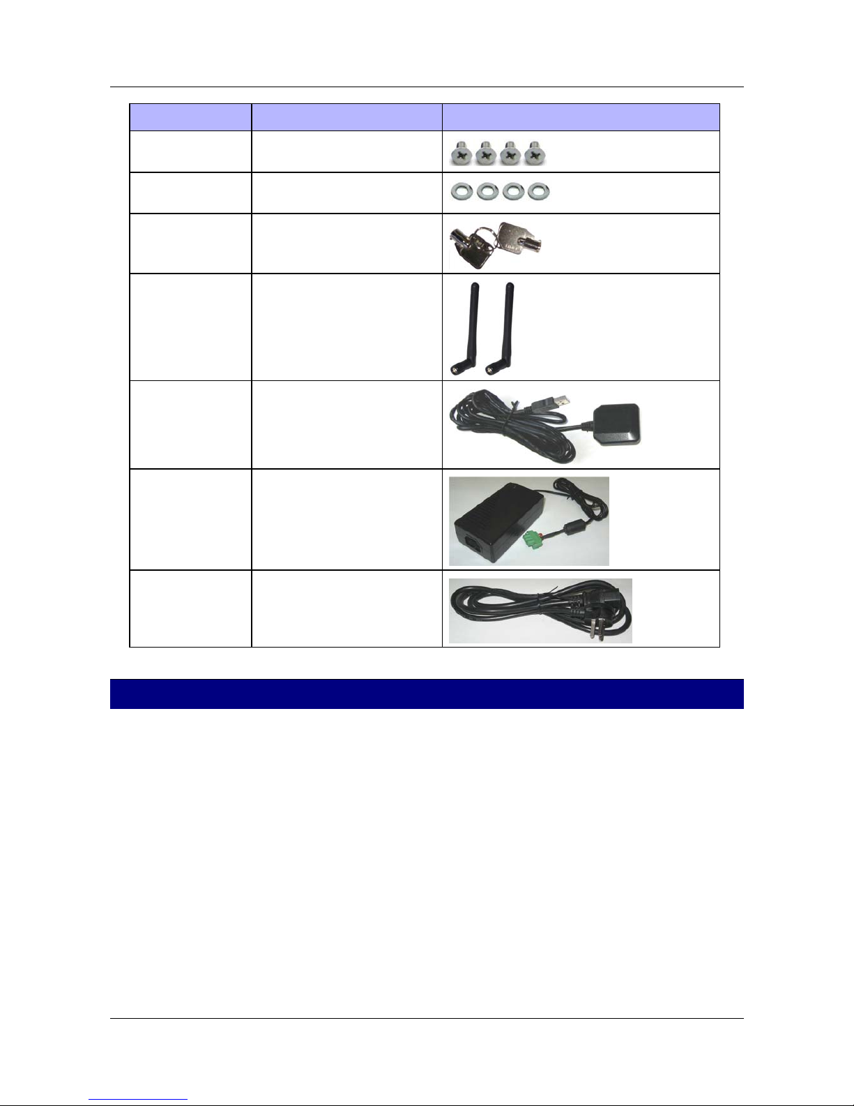
Item Description Illustration
4 screws Used to connect the supports to
the unit
4 washers Used to connect the supports to
the unit
2 keys Used to open or lock the hard-
drive compartment
2 WiFi antennas Enables the built-in WiFi
transmitter/receiver to connect to
WiFi access points
GPS antenna
(For mobile
installations only.)
Enables the built-in GPS receiver
to connect to satellites
Power-supply cable Connects the power-supply to the
unit
Power-connector
cable
Connects the power-supply to an
electric outlet
Peripheral Equipment
Cameras and other peripherals (sensors, activators, an HDMI monitor, etc.) are not included in the IVG400-N
package.
Only cameras that support the ONVIF protocol can be used with the IVG400-N. In addition, PoE (Power over
Ethernet) is supported for up to four cameras. If more cameras are required, please contact technical support for
information about connecting them to the system.
In principle, all ONVIF cameras are compatible with the system. Nonetheless, it is recommended to purchase
cameras that have already been tested by SerVision for compatibility:
• SerVision cameras
• Hikvision full HD cameras (1080p)
• Axis full HD cameras (1080p)
An HDMI monitor, used in conjunction with a standard mouse and keyboard, can be used to directly access the
IVG400-N’s system configuration. (If these items are not employed, initial configuration is performed by
connecting a PC to the IVG400-N unit.)
Peripheral Equipment 4
SerVision IVG400-N Quick-Start Guide
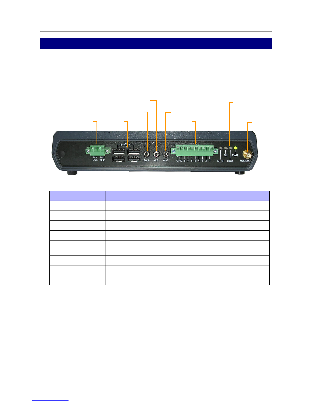
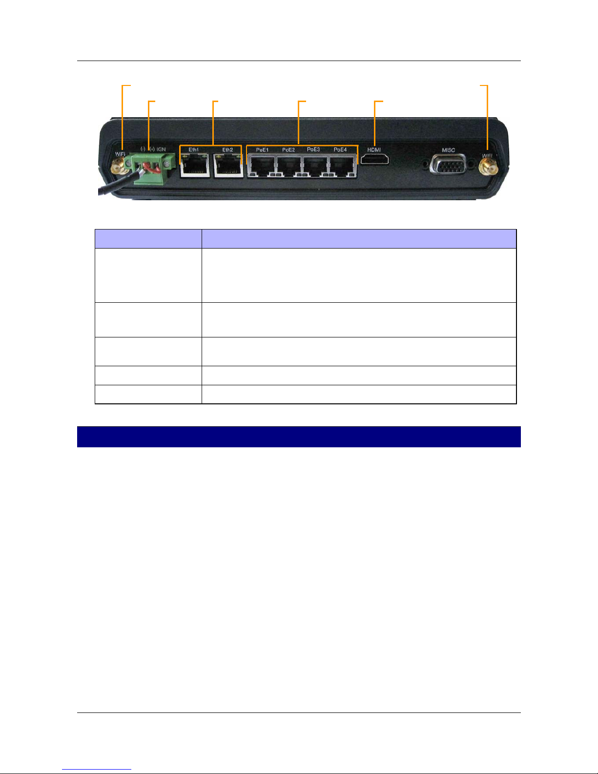
Diagrams of Connectors
IVG400-N has connectors on both the front and back panels, as described below.
Front Panel
The connectors and indicators of the front panel of the IVG400-N unit that are currently supported are described
below.
Diagrams of Connectors 5
Figure 1: IVG400-N front-panel connectors
Connector Description
Activators (Out1, Out2) Activator connectors for one or two
USB Ports Connectors for the GPS antenna and other optional peripherals
Audio Out (Aout) Connector for an external speaker or headphones
Audio In2 (Ain2) Connector for an active (self-amplifying) microphone
Audio In1 (Ain1) Connector for a passive microphone (Passive microphones require external
amplification.)
Sensors (In1 – In8) Sensor connectors for up to eight dry-contact input sensors
LED indicators Status indicators
Modem SMA connector for cellular modem
Rear Panel
The connectors of the rear panel of the IVG400-N unit that are currently supported are described below.
Sensors
In1–In8
A
ctivators
Out1, Out2
USB ports
LED
indicators
A
udio Out (Aout)
A
udio In2 (Ain2)
Audio In1 (Ain1)
Cellular
modem
SerVision IVG400-N Quick-Start Guide
Installing the IVG400-N Unit 6
Figure 2: IVG400-N rear-panel connectors
Connector Description
Power Connector for the power supply and, if required, for the ignition connection
Note: The connector in the picture above is for vehicle installations. If the unit is
to be installed in a stationary location, it will have a connector for an appropriate
power-supply cable.
Ethernet 1 and 2
(Eth1 and Eth2)
10/100 Base-T LAN connectors for connecting the unit to a PC and/or a LAN
Note: These connectors
do not
support PoE (Power over Ethernet).
PoE1–PoE4 10/100 Base-T LAN (Ethernet) connectors with PoE (Power over Ethernet) support
for connecting ONVIF cameras to the unit
HDMI Connector for an HDMI CCTV monitor
WiFi antenna 1 and 2 SMA connectors for WiFi antennas
Installing the IVG400-N Unit
The IVG400-N unit can be installed vertically or horizontally. If it is installed vertically, or it is installed on a
moving platform such as a vehicle, it must be mounted using the supplied supports. If it is installed in a stationary
location, it can be placed horizontally on a stable flat surface such as a table or shelf, and does not necessarily have
to be secured. Regardless of whether you mount the unit or not, ensure it has at least 3-5 centimeters (1–2 inches) of
space above it and on all sides for ventilation. (When the unit is mounted, the supports leave space between it and
the mounting surface, thus providing ventilation to the top of the unit.)
Mounting the Unit
When the unit is mounted, the top of the unit faces the mounting surface. If it is mounted vertically, the front and
rear panels should be on the sides; it does not matter which side faces up. These positions enable you to access all of
the unit’s connectors, as well as the compartment on the bottom of the unit in which the SIM-card slot and the
storage medium (hard drive or solid-state drive) are located.
D
To mount the IVG400-N unit:
1. Turn the unit upside down and attach each of the supports as follows:
f Place the support on the side of the unit, with the solid part around the body of the unit, and the screw
holes facing up.
Power HDMIPoE1–PoE4
WiFi antenna 2
Ethernet
1 and 2
WiFi antenna 1
 Loading...