

Embedded Video
May
2015
Gateway
System Guide
Configuration and management guide for SerVision
HVG400, UVG400, MVG200, MVG400, CVG, and CVG-M
Video Gateway models

SerVision Embedded Video Gateway System Guide
Trademarks & Copyright
Trademarks
All trademarks mentioned in this manual are the sole property of their respective manufacturers.
Copyright
SerVision Ltd., Jerusalem, Israel
www.servision.net • info@servision.net
© 2015 SerVision Ltd. All rights reserved.
Notice
Information in this document is subject to change without notice. SerVision Ltd. assumes no responsibility for any
errors that may appear in this manual. Companies, names and data used in examples herein are fictitious unless
otherwise noted. No part of this document may be copied or reproduced in any form, or by any means, electronic or
mechanical, for any purpose, without the express written permission of SerVision Ltd. SerVision Ltd. makes no
warranties with respect to this documentation and disclaims any implied warranties of merchantability or fitness for
a particular purpose.
sw CVG-M: v H1.2.2.26a.99
sw MVG200: v H1.2.2.26.a97
sw 4-channel: v HM4.2.2.26.a92
doc v 1-9
1

SerVision Embedded Video Gateway System Guide
Table of Contents
Getting Started 5
About this Guide 5
About Client Software 6
Before You Begin 6
Installing SVMultiClient 7
Opening the Configuration Utility 8
Overview of the Interface 10
Top-Level Menu Options 10
Status Bar 11
Using the Configuration Utility 11
Opening the Configuration Remotely 14
Opening the Configuration Manually 14
Configuring System Settings 16
General System Settings 17
About the General System Settings 17
Configuring General System Settings 21
Configuring a CCTV Monitor (TV-Out) 25
Configuring the Monitor to Display Video from the Video Gateway 26
Configuring the Monitor to Play Prerecorded Video 30
Setting the Unit Time 33
Updating the Date and Time Manually 35
Configuring Automatic Time Setting 37
LAN Settings 38
Modem 40
Video Gateway with Router 41
CVG-M 45
WiFi 47
Configuring the Unit to Connect to WiFi Access Points 47
Removing an Access Point from the List 52
Turning WiFi Off 52
Configuring the Unit to Function as an Access Point 53
Network Priorities 54
Port Forwarding 55
Proxy and DDNS Settings 57
Authentication 60
SMS and E-mail Notifications 61
SMS Message Templates 66
Testing Notification Settings 67
Automatically Uploading Video to an AVV Server 67
Viewing the List of Files on the AVV Server 72
Viewing Video from the AVV server 72
Disabling AVV 74
FTP Server Settings 74
Schedules 76
Configuring a Standard Weekly Schedule 78
Defining Holiday Schedules 80
2

SerVision Embedded Video Gateway System Guide
Defining a New Schedule Row 83
Audio Settings 85
Configuring Microphone and Speaker Volume 86
GPS 88
Configuring GPS 88
Erasing Recorded GPS Data 90
Configuring Camera Settings 91
About Brightness and Contrast Settings 91
Configuring Video Cameras 91
Configuring PTZ 95
Video Motion Detection (VMD) 96
About VMD Regions 96
About VMD Event Settings 96
About Responses to VMD Events 97
Configuring VMD Settings 97
Configuring Video Lost 102
Video Recording Settings 104
Configuring Video Recording 105
Advanced Recorder Settings 106
Restoring Default Recording Settings 110
Erasing Recorded Video 113
Erasing All Recorded Video from a Camera 113
Erasing All Recorded Video from the Storage Media 114
Restoring the Default Disk Allocation 116
Configuring Sensor and Activator Settings 119
Configuring Sensors and Activators 119
Configuring Sensor 1 to Switch Outlines 125
Configuring a Sensor to Control CCTV Display 126
Configuring an Activator as a Power Switch 127
Configuring Vehicle-Behavior Sensors 128
Configuring a Geo-Fence Sensor 128
Configuring a Speed-Limit Sensor 145
Configuring an Idle Monitor 146
Configuring a G-Force Sensor 147
Defining Alternate Outlines 149
Creating an Outline 149
Activating Outlines Manually 154
Saving Configuration Changes 156
Discarding Changes 158
Restoring Default Settings 159
Connecting to the Video Gateway 163
Connecting Through SVMultiClient 163
Connecting through the Configuration Utility 165
Viewing Events 166
Viewing Snapshots 168
System Diagnostics 171
System Statistics 172
Testing Remote Connections 173
Ping 173
Traceroute 176
3

SerVision Embedded Video Gateway System Guide
Maintenance 181
Upgrading the Firmware 183
Upgrading Firmware via a TVG Upload Server 183
Upgrading Firmware via the TVG Download Utility 185
Required Files 185
Downloading the Firmware to the Unit 185
Catch Boot Operation 187
Upgrading Router Firmware 191
Modifying the AES Key 192
Resetting the Unit 197
Restoring Factory Settings 198
Troubleshooting 201
Appendix A: Viewing Video on a CCTV Monitor (TV-Out) 207
Using Mouse/Touch Controls 209
Setting the Video Display Layout 211
Playing Back Recorded Video 212
Editing and Downloading Video Excerpts 217
Configuring Display Options 226
Viewing System Information on the Monitor 233
Using PTZ Controls 233
Recording Status Display 235
Appendix B: LAN Settings 237
About the Local IP Address of the Unit 237
About the Public IP Address of the Unit 237
Appendix C: Networks Managed by SerVision Routers 238
Appendix D: Power LED Behaviors 239
4

SerVision Embedded Video Gateway System Guide
Getting Started
SerVision’s embedded Video Gateways are compact Video Gateway units that provide state-of-the-art security
functionality for a wide range of environments, from offices and homes to vehicles and other moving platforms. All
units feature live video streaming, video recording and playback, motion detection, sensor management, and realtime event notification and device activation. These features can be accessed remotely via PC, PDA, or cellular
telephone.
All Video Gateway units can connect to computer networks, including local networks and the internet, using cablebased Ethernet connections. Some models also support wireless network connections via cellular networks and
WiFi. In addition, mobile models support GPS tracking, and can be integrated with some third-party fleetmanagement systems.
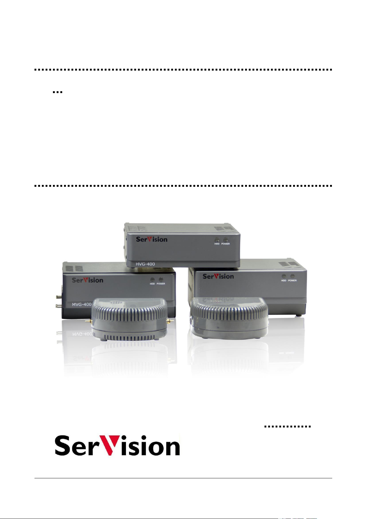
The following embedded Video Gateway models are currently available:
HVG400: A four-channel Video Gateway optimized for homes and small offices. The HVG400 features a
built-in hard drive capable of storing large quantities of recorded video and supports a cable-based connection
to a network.
UVG400: A four-channel Video Gateway that is ideal for deployment in locations where cabled network
connections are not available, such as building sites, parking lots, and horse stables. The UVG400 can connect
to a network via Ethernet, cellular, or WiFi and contains a built-in hard drive capable of storing large
quantities of recorded video.
MVG400: A four-channel Video Gateway designed for deployment in vehicles such as buses, trains, and
delivery trucks. The MVG400 contains a removable hard drive capable of storing large quantities of recorded
video. It can connect to cellular and wireless networks, and also supports GPS that enables remote users to
locate and track the vehicle in which it is installed.
MVG200: A two-channel Video Gateway designed for deployment in smaller vehicles such as cars, vans, and
mini-buses. The MVG200 records video and other data on a removable SD card. It can connect to cellular and
wireless networks, and supports GPS tracking.
CVG: A compact, two-channel Video Gateway optimized for streaming live video from indoor locations. The
CVG stores video and other data on a removable SD card, and can connect to cable-based networks.
CVG-M: A compact, two-channel Video Gateway optimized for streaming live video from vehicles. The
CVG-M can connect to cable-based and cellular networks, and also supports GPS that enables remote users to
locate and track the vehicle in which it is installed. It stores video on a removable SD card.
About this Guide
All Video Gateway models are configured using a browser-based configuration utility that is accessed via PC. This
guide explains how to use the configuration utility to configure and manage an embedded Video Gateway unit. The
guide assumes the unit is already installed in its intended location, all required devices are connected to it, and it is
connected to a power source and a network. For information about installing your Video Gateway unit, please refer
to its installation guide.
The following topics related to the configuration utility are covered in this manual:
Configuring the unit (page 8)
Connecting to the unit to check that the configuration settings are correct and to view video, snapshots, or
event information (page 163)
Resetting the unit (page 197)
Diagnosing system problems (page 171)
This guide also includes information about system maintenance and handling problems:
Upgrading the firmware (page 183)
Getting Started 5
SerVision Embedded Video Gateway System Guide
Restoring the factory settings of the unit (page 198)
Troubleshooting (page 201)
Most embedded Video Gateway models can be used in conjunction with a CCTV monitor. The monitor can be used
to view video from the cameras connected to the unit. Instructions for viewing video on a CCTV monitor are
included in an Appendix to this guide (see Appendix A: Viewing Video on a CCTV Monitor (TV-Out), page 207).
Because this guide relates to a number of different embedded Video Gateway models, certain parts of the manual
are only relevant to specific models. Information that only relates to some of the models is color-coded in teal. For
example, a paragraph that is only relevant to the MVG200 and CVG-M models would appear like this:
This is an example of a paragraph that only relates to the MVG200 and CVG-M models.
If an entire section is only relevant for particular models, the beginning and end of the section is marked and labels
appear at the top of the section. The labels indicate the models for which the section is relevant. For example, a
section that is only relevant to the MVG400, MVG200, and CVG-M models would appear like this:
GPS
Only the MVG400, MVG200, and CVG-M models support GPS position tracking.
The features of the two MVG models, MVG200 and MVG400, are nearly identical. For this reason, they are often
refered to collectively as the "MVG." Similarly, a single label may be used to represent both models:
Figure 1: Label representing both models of the MVG collectively
Because the Video Gateway models have slightly different features, their configuration is different in some cases.
Screenshots of the configuration utility that appear in this guide may be from a different model than the one you are
configuring, and may therefore not exactly match the screens you see. If the screen that is displayed differs
significantly from model to model, the name of the model from which the screenshot was taken appears in
parentheses in the caption below the screenshot.
About Client Software
Client software is used for accessing the Video Gateway unit remotely in order to view video and events and control
the system in various ways. This guide includes a general overview of SVMultiClient, SerVision’s PC-based client
software. A complete user guide for SVMultiClient is available on the SerVision website
(http://www.servision.net). SerVision also offers client software for certain cellular telephones, tablet PCs, and
PDAs. These applications, and user guides for them, can be downloaded from the SerVision website. In addition,
SVControlCenter is a complete control-center solution that includes powerful client features, for enterprises
managing sizable numbers of Video Gateways. Additional information about SVControlCenter is available on the
SerVision website and from SerVision customer-service representatives.
Before You Begin
Before the Video Gateway unit can be configured, the hardware should be set up as follows:
The Video Gateway unit should be installed and connected to a power supply. (Installation guides for all
Video Gateway models are available on the SerVision website.)
Getting Started 6
SerVision Embedded Video Gateway System Guide
All the cameras and optional devices (sensors, activators, etc.) should be connected to the Video Gateway unit
and to their power supplies, as necessary.
A PC should be on the same LAN as the Video Gateway or connected to the unit by a LAN cross cable.
There are two ways that you can connect a PC to the same LAN as an MVG400 or UVG400:
Using the supplied Ethernet (network) cable, connect the network connector of the PC to one of the Ethernet
In connectors on the rear panel of the unit. The PC will then be included in the network managed by the
router. (It is preferable to use this method the first time you connect to the unit, before it has been configured.)
Using the supplied Ethernet (network) cable, connect the Ethernet Out connector on the rear panel of the unit
to a LAN connection point. Connect the PC to the same LAN through a different connection point.
NOTE: Do not connect a LAN connection point to one of the Ethernet In connectors; if you do, the system
will not function properly and will reset itself continuously.
Installing SVMultiClient
The simplest way to open the Video Gateway’s configuration utility is by using the SVMultiClient application on a
PC that is on the same LAN as the Video Gateway (see Before You Begin, page 6). Thus, before you begin
configuring the Video Gateway, you should install SVMultiClient on the computer that you will use for the
configuration tasks.
After the unit is configured, you can check the installation and configuration using the SVMultiClient you installed
on the PC (see Connecting to the Video Gateway, page 163). If this is successful, you can then install
SVMultiClient on a remote computer and connect to the Video Gateway via the internet.
NOTE: This chapter explains how to get started using SVMultiClient on a PC that is on the same LAN as the
Video Gateway so that you can configure the system and make sure it is working properly. For
complete information about connecting to SVMultiClient, locally or remotely, and using
SVMultiClient to view video, monitor events, and control devices, please refer to the SVMultiClient
User Guide.
To install the SVMultiClient application on the PC:
1. Download the latest version of the SVMultiClient installation program from the SerVision website
(http://www.servision.net). The installation file is called Setup-MultiClient-SV-x.x.x.x.exe (The
software version number appears in place of “x.x.x.x”.)
1. Double-click the installation file. The setup program starts.
Note: If a Microsoft Windows Security Warning dialog box is displayed, click Run.
2. Follow the on-screen instructions.
When the installation is completed, a SVMultiClient application icon is placed on your desktop.
Figure 2: SVMultiClient desktop icon
Getting Started 7
SerVision Embedded Video Gateway System Guide
Connection
panel
Search
Opening the Configuration Utility
This section explains how to work with the configuration utility – how to open it, access its main menu, and
navigate to the various configuration screens. The menu options and their settings are described in detail in the
following chapters.
When you first open the configuration utility, you should open it through SVMultiClient, as explained in this
section. This method of opening the configuration utility is recommended whenever SVMultiClient is on a PC that
is on the same network as the Video Gateway (or the PC and the Video Gateway are connected via a LAN cross
cable).
No internet connection is required to configure the Video Gateway. Once the network settings of the unit have been
configured in such a way that the unit can be accessed remotely via the internet, the configuration utility can also be
accessed remotely. For additional information, see Opening the Configuration Remotely, page 14.
NOTE: The configuration utility is compatible with Internet Explorer and Firefox.
To open the configuration utility:
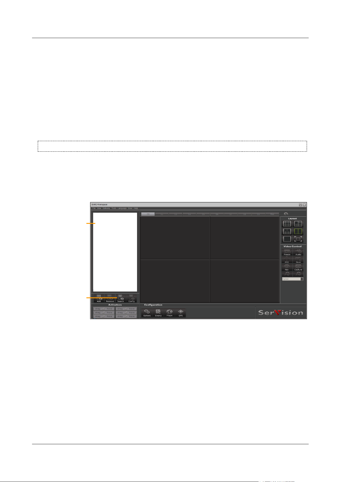
1. Open the SVMultiClient application by double-clicking the desktop icon or by selecting it in the Start menu
(Start>Programs>SerVision>SVMultiClient>SVMultiClient).
2. In SVMultiClient, at the bottom of the Connection Panel, click the Search button.
Figure 3: Search button
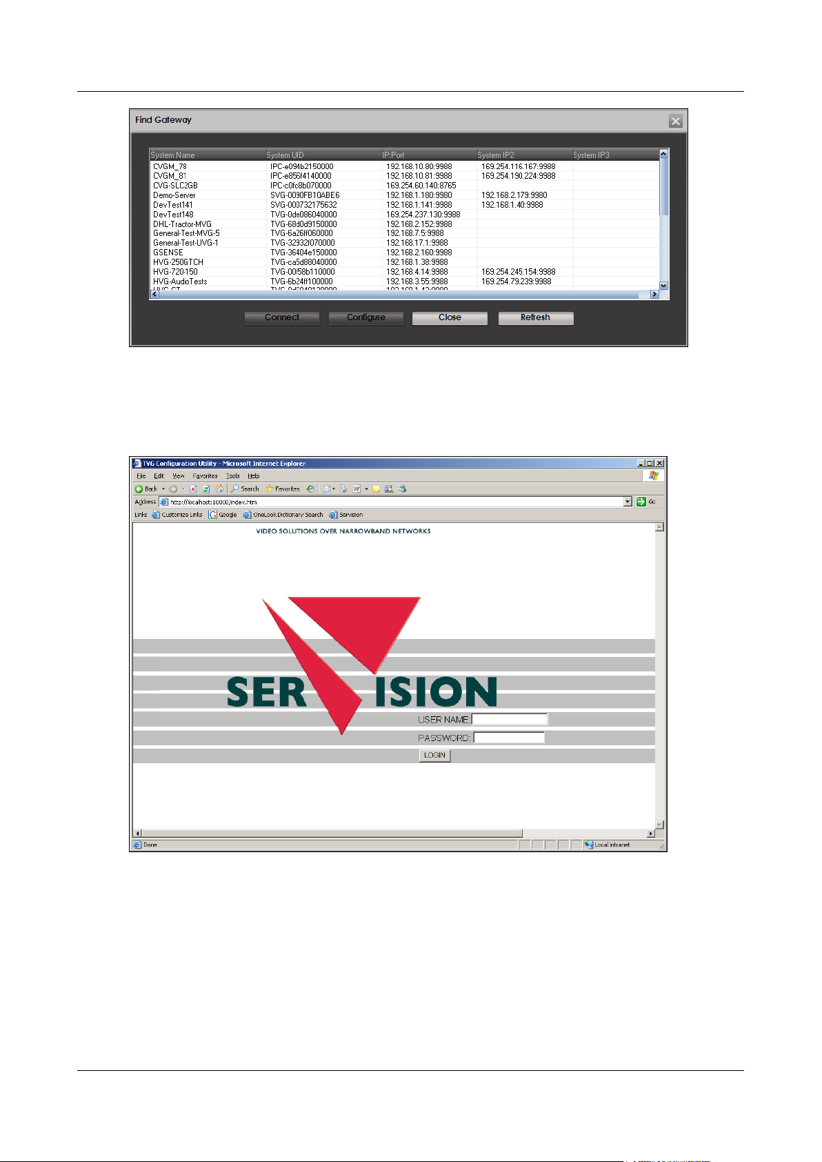
The Find Gateway dialog box opens, and displays a list of all the SerVision systems connected to the
network.
Getting Started 8
SerVision Embedded Video Gateway System Guide
Figure 4: Find Gateway dialog box
Note: It may take a few minutes before the Video Gateway unit appears in the list.
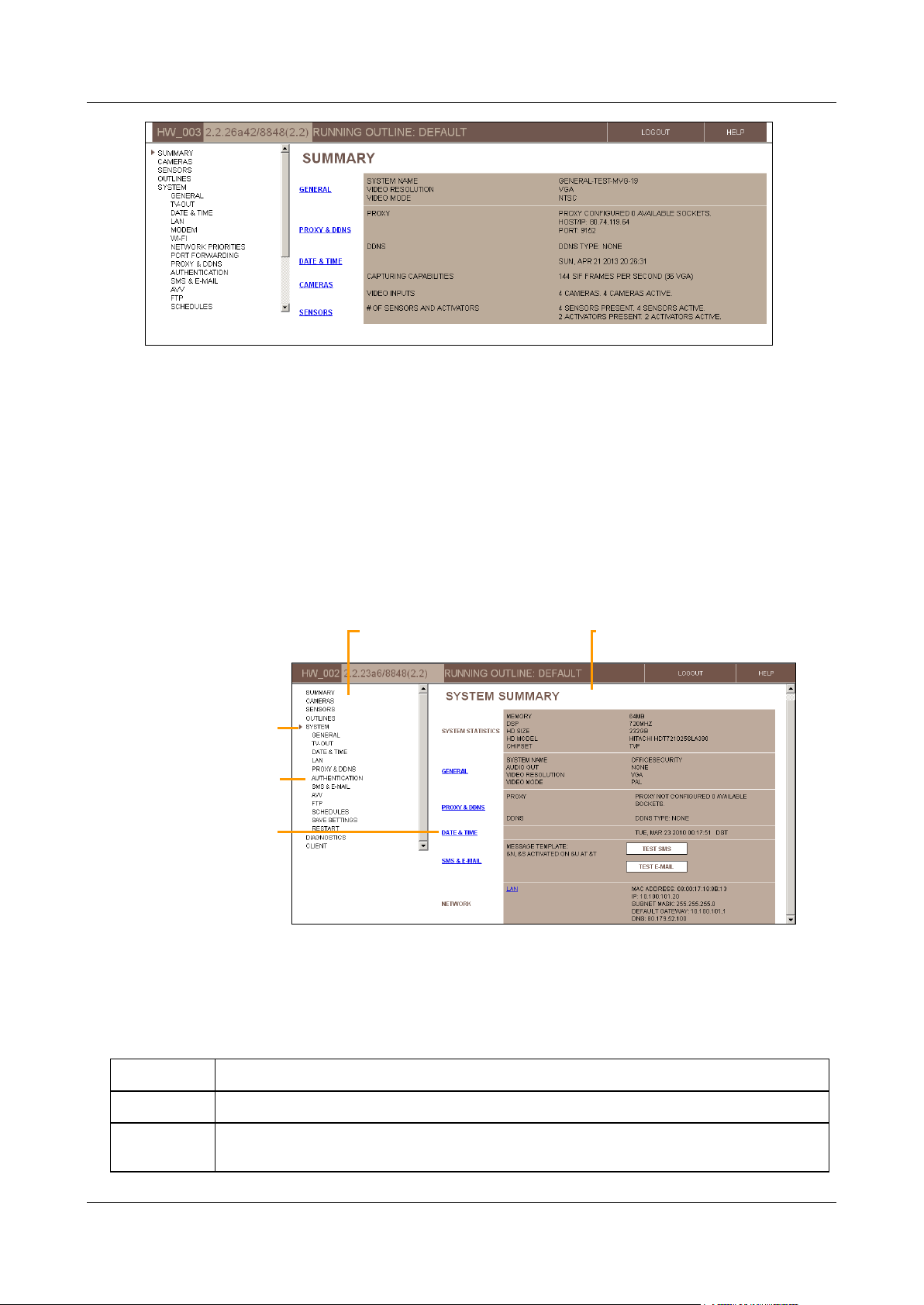
3. Select the Video Gateway and then click Configure. A browser window opens and displays the configuration
Login screen.
Figure 5: Login screen
4. Fill in the User Name and Password fields.
Note: By default, the username is svuser and the password is servconf. Use these values the first time
you log into the configuration utility. Once you have logged in, it is recommended that you change these
values (see Authentication, page 60).
The Summary screen opens:
Getting Started 9
SerVision Embedded Video Gateway System Guide
Summary
Displays a summary of the system's settings and status
Cameras
Configuration of video settings for each camera, including PTZ settings (remote camera control),
VMD (Video Motion Detection), and recording settings
Links to lower-level
screens
Selected top-level
screen
Lower-level option
Main Menu
Screen
Figure 6: Summary screen
Overview of the Interface
The configuration utility consists of screens that are displayed on the right side of the window and a Main Menu in
a sidebar on the left side of the window.
The Main Menu has a hierarchic tree structure. When you select one of the top level options, lower-level options
appear below it in the menu.
Top-level menu options generally open summary screens that display the current settings in a given category and
may include links from which you can access some of the lower-level screens in the selected category. Lower-level
screens are used to modify configuration settings and manage the system.
Figure 7: Elements of the interface
Top-Level Menu Options
The following top-level menu options are available:
Getting Started 10

SerVision Embedded Video Gateway System Guide
Sensors
Configuration of sensors and activators
Outlines
Configuration of sets of different camera and sensor settings that can be activated either
manually or automatically in response to sensor events or according to a fixed schedule
System
Configuration of general system settings, including network settings, unit date and time,
authentication, configuration of SMS and e-mail notifications, and TV-Out settings
Saving configuration changes on the unit and restarting the unit
Diagnostics
Tools for monitoring and testing the system
Client
Viewing lists of events that were detected, selecting events to download to an FTP server,
viewing live snapshots from a camera
Model
Logout
Help
Version
Outline
Status Bar
A status bar at the top of the screen contains the following elements:
Figure 8: Status bar elements
Model: Video Gateway model number
Version: Firmware version
Outline: Name of the current outline (see Defining Alternate Outlines, page 149)
Logout button; click to log out of the configuration utility and display the Login screen again
Help button; click to open the SerVision website in a browser window. The website includes information
about configuring and working with your Video Gateway system, including the most up-to-date version of this
manual (under Support->Documentation->Manuals and Product Overviews)
Using the Configuration Utility
Typically, the configuration process proceeds as follows:
Getting Started 11
SerVision Embedded Video Gateway System Guide
Update confirmation message
Update
To configure a Video Gateway unit:
1. In the Main Menu, click one of the top-level options, e.g., Cameras or Sensors. The selected summary
screen opens.
2. Click an option in the Main Menu or a link in the summary screen to open the desired lower-level screen. The
screen opens.
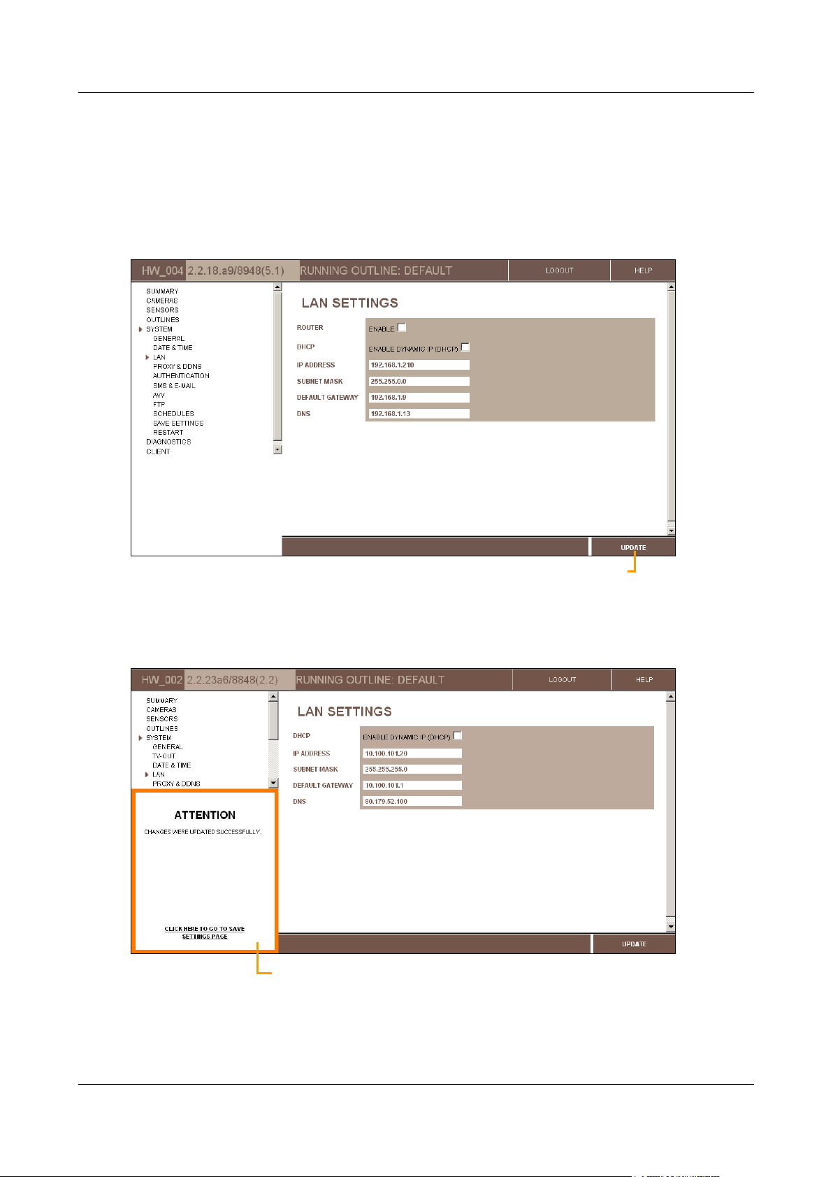
3. Modify the settings in the settings in the screen as necessary, and then click Update to store them on the unit.
Figure 9: Update button
The changes are saved in a temporary cache on the unit, and an Update Confirmation (ATTENTION) message
appears at the lower left of the screen, below the Main Menu.
Figure 10: Update confirmation message
Getting Started 12
SerVision Embedded Video Gateway System Guide
Note: If the update confirmation message does not appear, or an error message appears, all changes made
since the last successful update of the page are discarded.
4. To modify additional settings, navigate to the relevant screen and make the changes as necessary. Click
Update in each screen when you are finished modifying its settings. (You can continue modifying the settings
in the same screen, if necessary; just be sure to click Update before you navigate to a different screen to
ensure the settings are saved as they are displayed.)
5. When you have updated all the settings as necessary, do one of the following:
In the update confirmation message, click “Click here to go to Save Settings page.”
In the Main Menu, under System, click Save Settings.
The Save Settings screen opens:
Figure 11: Save Settings screen
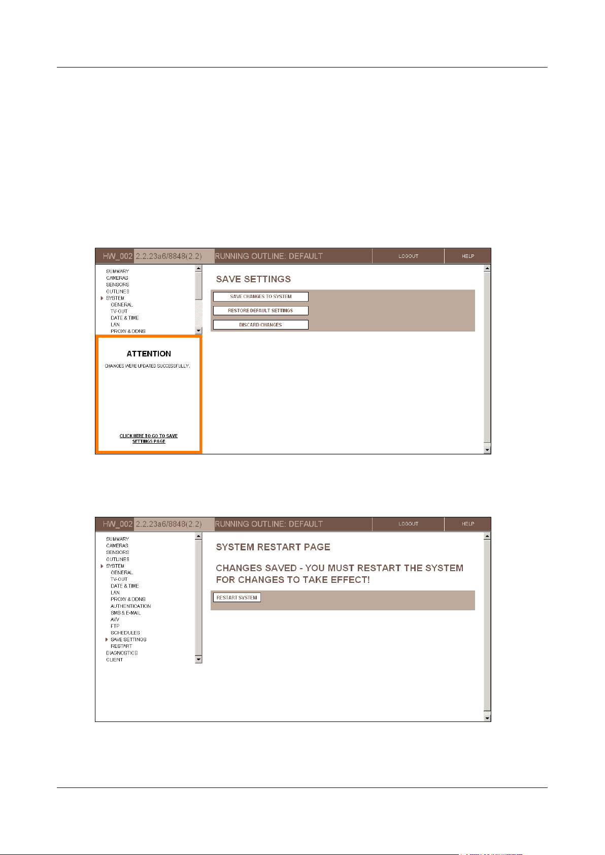
6. In the Save Settings screen, click Save Changes to System. The unit stores the changes permanently, and
the System Restart Page screen opens:
Figure 12: System Restart Page screen
Getting Started 13

SerVision Embedded Video Gateway System Guide
7. Click Restart System. The unit restarts, and the changes are implemented. You are automatically logged out
of the configuration utility.
Note: Most changes to the settings in the configuration screens only take effect on the Video Gateway unit
after they are saved and the unit is restarted, as describe in steps 5–7. For additional information, see Saving
Configuration Changes, page 156.
Note: For security reasons, a configuration session times out after 15 minutes. If the configuration utility is
open with no user activity (pages loaded) for more than 15 minutes, you must perform the login procedure
again to continue configuring the Video Gateway unit. Configuration changes that were made during the
timed-out session are not discarded, as long as Update was clicked in the relevant screen before the time-out
occurred.
Opening the Configuration Remotely
Once the unit has been configured for remote client access via the internet (see LAN Settings, page 38), you can also
access the configuration utility remotely via the internet. To do this, all you need is a PC that is connected to the
internet. You can then access the configuration utility in one of the following ways:
Through SVMultiClient: Connect to the Video Gateway and use SVMultiClient to access the configuration
utility, as explained below. (For additional information about working with SVMultiClient, please refer to the
SVMultiClient User Guide.)
Manually through a browser: Enter the address and port in the Address field of a browser window, as
described under Opening the Configuration Manually, page 14.
Both of these methods can also be used to access the configuration utility over the internet through a proxy
connection.
To access the configuration utility remotely through SVMultiClient:
1. Connect to the Video Gateway through SVMultiClient.
Note: SVMultiClient's Search function does not work over the internet. Therefore, you will have to manually
add and configure the connection to the Video Gateway. For information about how to do this, please refer to
the SVMultiClient User Guide.
2. In the Connection Panel (left panel) of SVMultiClient, select the Video Gateway.
3. At the bottom of the Connection Panel, click the Config button. A new browser window opens, and
automatically connects to the configuration utility login page for the Video Gateway.
Note: If you cannot connect remotely through port 10000, the login page will not appear at this point, and the
browser will display an error message instead. Change the port number in the Address field of the browser
from 10000 to the port that is set in the router's port forwarding settings (see General System Settings,
page 17), and press Enter to reload the page. The login page should then appear. For additional information,
see Opening the Configuration Manually, below.
Note: If more than one SerVision Video Gateway is connected to the internet via the same router, each of
them must use a different port. When you click Config in SVMultiClient, the browser automatically connects
to port 10000. As a result, SVMultiClient may initially connect you to the wrong Video Gateway unit. In this
case, you should manually correct the port number in the Address field of the browser, as explained in the
previous note.
Opening the Configuration Manually
The configuration utility can be opened manually in a browser using the IP address and port of the unit. This is
particularly useful in situations in which you cannot open the configuration utility through SVMultiClient. This is
most likely to occur when you are opening the configuration utility remotely and either do not have access to
SVMultiClient or cannot connect to the unit remotely through port 10000.
Getting Started 14
SerVision Embedded Video Gateway System Guide
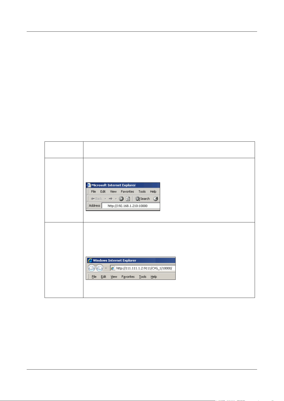
Type
Direct (local or
remote)
http://IP:port
For example, if the Video Gateway’s IP address is 192.168.1.210 and you are
connecting on port 10000, enter http://192.168.1.210:10000, as in figure 13:
Figure 13: Address for configuring a unit with a static IP
Proxy
http://Proxy-IP:Proxy-port/Video Gateway name/Video Gateway
port/
For example, if the proxy server’s IP address is 111.111.1.2, its port number is 9111,
the name of the Video Gateway is CVG_1, and its port is 10000, enter
http://111.111.1.2:9111/CVG_1/10000/, as in figure 13:
Figure 14: Address for configuring a unit via a proxy server
Note: Be sure to include the slash (/) at the end of the address.
To open the configuration utility manually, you must know the network address (IP or hostname) of the Video
Gateway and the port allowing access to the configuration utility. The required network address depends on whether
you are accessing the configuration utility through a local connection (through the same LAN or through an
Ethernet cross cable) or a remote connection (through the internet):
Local connection: The network address is the private IP address of the Video Gateway on the local network.
This can either be its dynamic IP, or, if it has one, its static IP. The port is 10000.
Remote connection: The network address is the public IP or hostname of the router through which the Video
Gateway connects to the internet. The port is the port that allows access to the configuration utility via port
forwarding.
If you connect through a proxy connection, you must also know the network address and port of the proxy server.
To open the configuration utility manually:
1. Open a web browser.
2. In the Address field of the browser, enter the IP address and system port number of the Video Gateway, as
follows:
3. Press Enter. The configuration utility Login screen opens.
4. Log into the configuration utility as usual (see page 9).
Getting Started 15
SerVision Embedded Video Gateway System Guide
Configuring System Settings
System settings include system-wide settings, such as the name of the unit, date and time settings, and network
configuration.
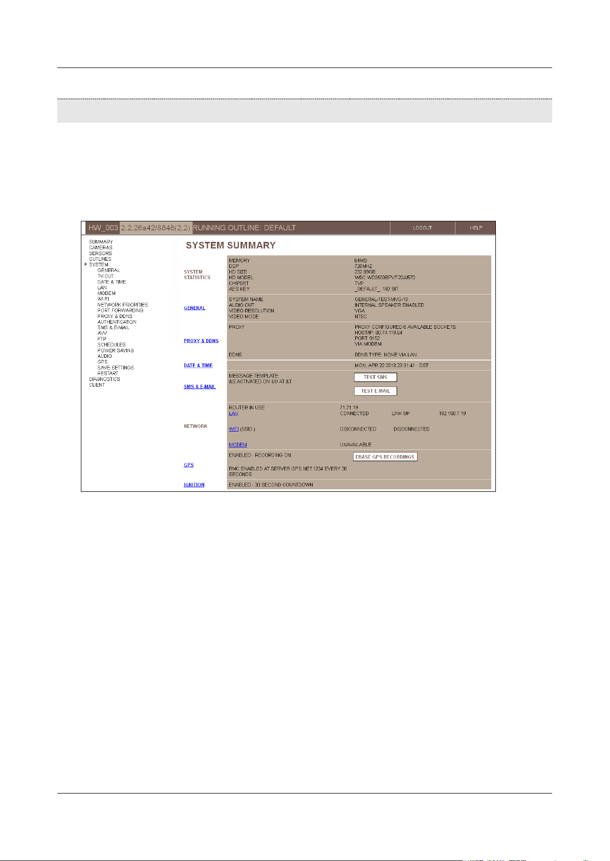
The System Summary screen summarizes the current system settings and provides links to some of the system
configuration screens in which the system settings can be modified. It also includes information about the Video
Gateway unit and the network, and, depending on the configuration settings, may include buttons that you can use
to test the current e-mail and SMS notification settings.
Figure 15: System Summary screen (MVG)
The following system-configuration screens are available:
General: Unit name, port number, and activation of certain options (see page 17)
TV-Out: Configuration of a closed-circuit monitor (CCTV) connected to the Video Gateway (see page 25)
Date & Time: Automatic and manual time setting (see page 33)
LAN: Ethernet network settings (see page 38)
Modem: Cellular modem configuration (UVG400, MVG, and CVG-M only; see page 40)
WiFi: Wireless network connection and access-point settings (UVG400 and MVG only; see page 47)
Network Priorities: Ranking the available network connections for outgoing communication from the unit to
other networks, to indicate which connections should be tried first (UVG400 and MVG; see page 54)
Port Forwarding: Configuring ports that allow external devices to connect to devices within the local
network managed by the Video Gateway’s router (UVG400 and MVG only; see page 55)
Proxy and DDNS: Proxy and DDNS settings (see page 57)
Authentication: Usernames and passwords for accessing and configuring the unit (see page 60)
Configuring System Settings 16
SerVision Embedded Video Gateway System Guide
SMS & E-mail: Event notification settings (see page 61)
AVV: Configuration of automatic uploading of video to an FTP server (see page 67)
FTP: Configuration of manual uploading of video to an FTP server (see page 74)
Schedules: Configuring the unit to automatically switch the running outline at specified times (see page 76)
Power Saving: Configuring sleep-mode (in development, for use with certain control-center applications;
MVG only)
Audio: Configuring microphones and speakers (see page 85)
GPS: Configuring GPS settings (MVG and CVG-M only; see page 88)
Save Settings: Saving configuration changes (see page 156)
Restart: Restarting the unit in order to fully implement configuration changes or improve system performance
(see page 197)
To open the System Summary screen:
In the Main Menu, click System.
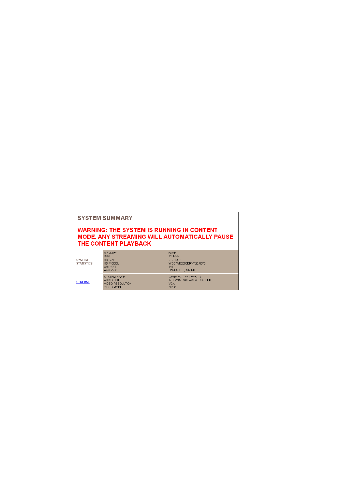
NOTE: If Content mode is enabled in the TV-Out settings, a warning message appears at the top of the System
Summary screen:
For additional information, see Configuring the Monitor to Play Prerecorded Video, page 30.
General System Settings
The general system settings are the basic settings for the unit: the name of the unit, the port it uses for
communication, video resolution and type, and activation of certain optional features.
About the General System Settings
This section contains background information about the general system settings.
Ports
The unit has two access ports:
Port 10000, which is intended for configuration and is always open for incoming connections.
Configuring System Settings 17
SerVision Embedded Video Gateway System Guide
System port, which is intended for client connections, and can be configured. The default number of this port
appears on the sticker on the underside of the unit. (It is usually 9988.) You can configure this port as
necessary to suit the requirements of your network.
NOTE: If port forwarding in your network cannot be set up for port 10000, you can use the system port for
remote configuration as well as client connections.
Video Resolution
The Video Gateway can capture video in one of the following resolutions:
VGA: This resolution is the standard used by digital screens such as computers and cellular phones. When
VGA is selected, the full-screen resolution is 640x480 pixels. Available smaller screen sizes are SIF (one
quarter of full screen; 320x240 pixels) and QSIF (one sixteenth of full screen; 160x120 pixels).
D1: This resolution is the standard used by analog screens such as televisions. When D1 is selected, full-
screen resolution is 704×480 pixels for NTSC systems and 704x576 pixels for PAL systems. Available
smaller screen sizes are CIF (one quarter of full screen; 352x240 pixels for NTSC systems and 352x288 pixels
for PAL systems) and QCIF (one sixteenth of full screen; 176x120 pixels for NTSC systems and 176x144 for
PAL systems).
VGA normally displays properly even on analog equipment such as CCTV screens. If your system supports both
resolutions, it is recommended that you select VGA resolution because it requires slightly less system resources.
Ignition-Off Shut-Down
The Ignition settings define whether the MVG or CVG-M unit should automatically shut down when the vehicle
ignition is turned off and, if so, how long the unit should continue operating after the ignition is turned off before it
shuts down.
Download Optimizations
Downloading recorded video uses system resources that would otherwise be available for other functions such as
recording or streaming live video. Download optimization settings are used to tweak the allocation of system
resources between downloading and other system processes.
These optimization settings are most important for mobile Video Gateways, which may be subject to vastly
different network conditions at different times. For example, if a bus is on the road, it typically only has access to a
cellular connection, which has very limited bandwidth, but when it is the bus yard, it probably also has access to a
high-speed WiFi network. In this case, downloading of the recorded video can be scheduled for times when the bus
is in the yards. Since recording video is only necessary when the bus is on the road, it is best to suspend recording
while downloading is being performed, because this speeds up the downloading process.
The following download-optimization options can be selected:
Enabled: Prevents the unit from initiating transmission of a new stream of recorded video to a client device,
and from beginning to download live or recorded video to a client device, when video is already being
downloaded from the unit. Live streams can be initiated, and all processes that are already in progress
(streaming of live or recorded video to a client or to a connected CCTV monitor, and downloading of video)
continue uninterrupted, unless one or more of the download-optimization options described below are
selected.
Stop Recording on Download: In addition to the above, stops all video recording on the unit when video is
being downloaded from the Video Gateway. This option increases the download speed, because it allocates
more of the unit’s resources to the download task. However, it also means that there may be gaps in the
recorded video at the times that the video is downloaded.
Configuring System Settings 18

SerVision Embedded Video Gateway System Guide
Close All Tasks on Download: Prevents the unit from performing any other jobs – accepting new
connections, streaming live or recorded video, recording video, or downloading other video – when
downloading is in progress.
Block New Connections while Downloading: Prevents the unit from accepting any new connections from
clients while downloading of recorded video is taking place. When this option is selected, transmission of new
live or recorded video streams to client applications does not begin while downloading is underway, but
existing streams are not closed. When this option is not selected, the process of downloading may take
somewhat longer to be completed. In addition, the framerate of video displayed in the client may be reduced at
times while the download is in progress.
Disable TV-Out While Downloading: If a CCTV monitor is connected to the Video Gateway, stops
streaming of video to the monitor while downloading of recorded video is taking place
Additional System Settings
A number of other system settings can be configured in the General System Settings screen:
Video Authentication: Adds a digital signature to each frame of video captured by the system. This signature
makes it possible to identify frames that have been tampered with. When a SerVision client application plays
video that has a digital signature and discovers a frame that has been changed from its original state, the status
of the stream indicates that the stream was modified. (Note: Only the current versions of SVMultiClient and
the Player support this feature.)
Outline Switching: Defines whether the system can activate different outlines automatically and, if so, what
type of trigger will cause the system to switch to a different outline, sensor events (from Sensor 1) or a
schedule. If neither type of automatic outline switching is selected, you can manually change the active outline
at any time. For additional information, see Defining Alternate Outlines, page 149.
Network Speed Optimization: Activates zero-latency handling of video packets. Activating this option may
increase the transmission speed of video from the Video Gateway to client PCs that are on the same LAN as
the Video Gateway. This feature is not recommended for use with other types of client connections (internet,
cellular, etc.). In addition, it is only recommended for use if video transmission speed is problematic. It usually
has a more marked effect on video streaming than on video downloading.
Network TCP Optimization: Opens all sockets with TCP_NODELAY activated. Activating this option may
increase the transmission speed of video from the Video Gateway to client PCs that are on external networks –
internet, cellular, etc. This feature is not recommended for use with clients that are on the same LAN as the
Video Gateway. In addition, it is only recommended if video transmission speed is problematic. It usually has
a more marked effect on video streaming than on video downloading.
SMS on System Start: Sends SMS notifications to all SMS recipients whenever the Video Gateway starts
running. For information about defining SMS recipients, see SMS and E-mail Notifications, page 61.
ADAM Sensors: Enables the activation of sensors that are connected to the Video Gateway unit through an
ADAM module. For additional information, see Configuring Sensor and Activator Settings, page 119.
IA Sensors and Activators: Enables the activation of sensors and activators that are connected to the Video
Gateway unit through an IA 3126-2 relay board. For additional information, please refer to your unit’s
installation manual.
Maximum Recording Length: Automatically erases recorded video after a specified period of time.
Publish System Name: Sends the name and IP address of the Video Gateway to the ARP system of the local
network so that the ARP system can translate the name of the Video Gateway to its IP address. This enables
local users to access the Video Gateway using its name.
Ignore VGA in RT: Tells the Video Gateway not to send VGA video streams (of live or recorded video) to
client applications; when a client requests a VGA stream, the stream is sent in a lower-resolution, although the
VGA image size is retained. Activating this option enhances the stability of the stream when bandwidth is
limited, such as when the Video Gateway transmits video streams over a cellular connection. This option does
not affect video downloading; video can be downloaded in full VGA resolution even if this option is selected.
Configuring System Settings 19

SerVision Embedded Video Gateway System Guide
Real Time Bitrate Control: Tells the Video Gateway to monitor the video transmission, identify situations in
which packets are not being transmitted quickly enough because of bandwidth limitations, and automatically
modify the bitrate of the video to suit the available bandwidth. Activating this option enhances the stability
and quality of the stream when bandwidth is limited, such as when the Video Gateway transmits video streams
over a cellular connection. This option does not affect video downloading; video can be downloaded in full
VGA resolution even if this option is selected.
Time Stamp on Snapshot: Imprints a timestamp indicating when the picture was taken before downloading a
snapshot to a client.
Allow Only Encrypted: Tells the Video Gateway to encrypt all video data before transmitting it. When this
option is selected, clients cannot connect to the Video Gateway unless AES encryption is turned on in the
client application.
Note: If clients connect to the Video Gateway through a proxy server, when this option is selected, the video
data is transmitted from the Video Gateway to the proxy server in encrypted form. If you want it to be
encrypted when it is transmitted from the proxy server to clients, you must select Encrypt Proxy
Communication in the Proxy and DDNS Settings screen. For additional information, see Proxy and DDNS
Settings, page 57.
Note: For information about AES encryption, see Modifying the AES Key, page 192.
Event on Ignition: Generates an Ignition event whenever the vehicle ignition is turned on.
Maximum Allowed Streams: By default, the Video Gateway can transmit up to 20 video streams at one time.
This option can be used to further limit the number of simultaneous video streams that can be transmitted. This
may be useful, for example, if the local network to which the Video Gateway is connected cannot support so
many video streams at one time. If the maximum number of streams has been reached, clients requesting
additional streams from the Video Gateway receive an error message saying "Stream not available."
Configuring System Settings 20
SerVision Embedded Video Gateway System Guide
System Name
Assign a name to the Video Gateway unit (up to 20 Unicode (UTF-8) characters).
This name is used to identify the unit in client applications such as SVMultiClient, in
SMS and e-mail notifications, in AVV file names, and on the proxy.
Note: Spaces and underscores in the name may cause problems with various
network functions, such as e-mail notifications, proxy, and DDNS. Therefore, it is
recommended not to include any spaces or underscores in the name.
System Port
Fill in the client access port of the Video Gateway unit.
Configuring General System Settings
To adjust the general system settings:
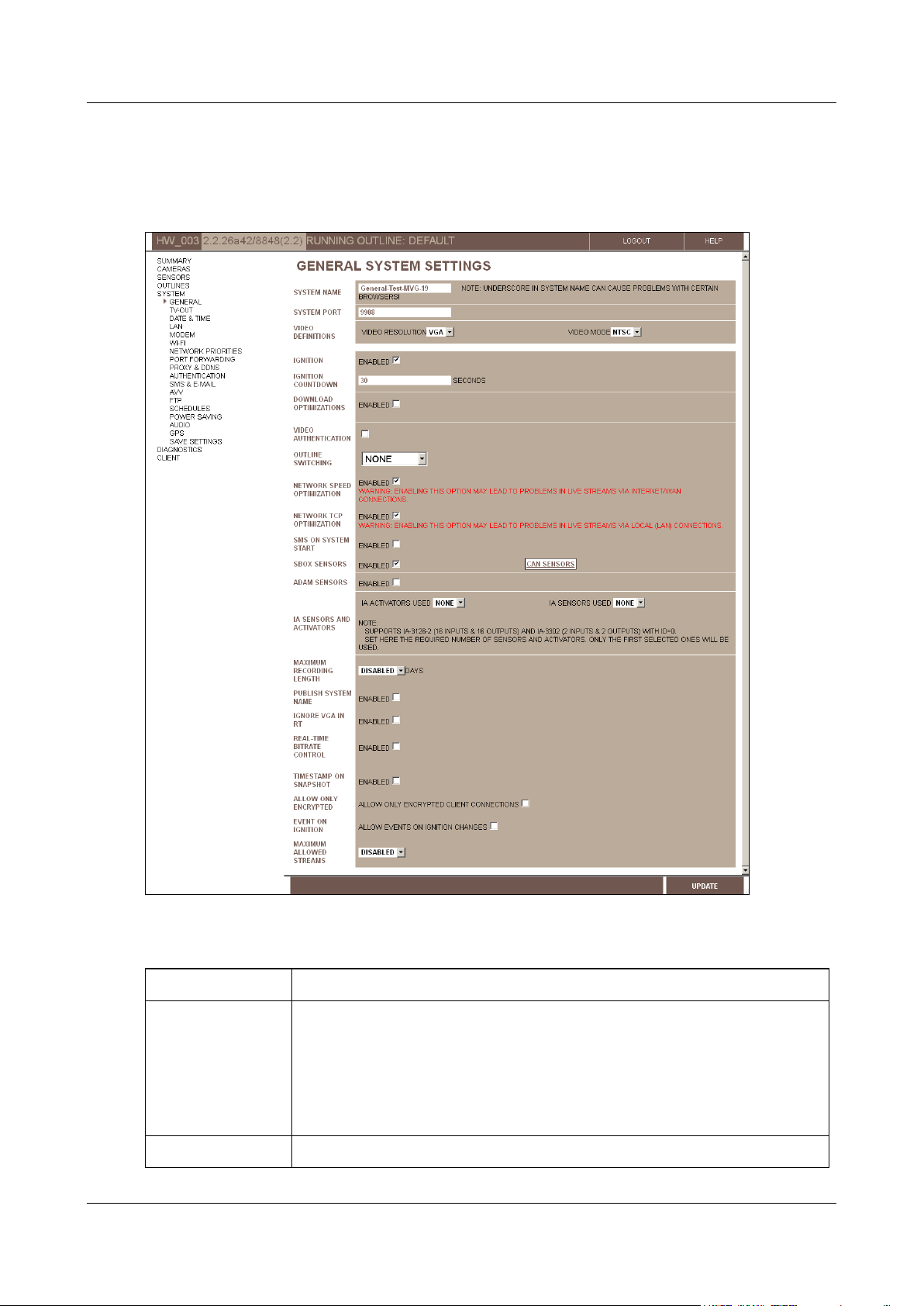
1. In the Main Menu, under System, click General. The General System Settings screen opens:
Figure 16: General System Settings screen (MVG)
2. Fill in the fields as follows:
Configuring System Settings 21

SerVision Embedded Video Gateway System Guide
Note: If you want to access the unit remotely and cannot set up port forwarding
for port 10000 in your network, you can also access the configuration utility using
this port.
Video Resolution
Select the video resolution (VGA or D1). VGA is recommended for most applications.
Note: If you change the video resolution, all recorded video is erased from the unit.
Video Mode
Select the video format (PAL or NTSC) used by the camera.
Note: NTSC is generally used in North America. PAL is standard in most other
locations. For additional information, consult the camera documentation.
Note: If you are connecting a CCTV monitor to the Video Gateway, ensure that the
monitor supports the video mode selected here. Some SECAM monitors will also
work when the PAL video mode is selected.
Note: When D1 video resolution is selected, and you change the video mode, all
recorded video is erased from the unit.
Ignition
(MVG and CVG-M
only)
Select this option if you want the unit to power down automatically whenever the
ignition is turned off. If you do not select this option, the unit operates continuously
as long as it has a power supply.
Note: This setting only affects the unit if the unit is connected both directly to the
battery and to the ignition. Otherwise, the unit operates continuously as long as it
has a power supply. (For additional information, please refer to the unit’s
installation guide.)
Ignition Countdown
(MVG and CVG-M
only)
Select the amount of time that the unit should continue operating after the vehicle
ignition is turned off, in seconds.
Note: This setting only affects the unit if the unit is connected both directly to the
battery and to the ignition. Otherwise, the unit operates continuously as long as it
has a power supply. (For additional information, please refer to the unit’s
installation guide.)
Note: This field only appears if the Ignition checkbox is selected.
Download
Optimizations
Select this option if you want to activate any of the download optimization settings.
If this option is selected, while downloading is in progress the Video Gateway will fill
new requests from clients for live-video streaming, but it will not fill new requests
for playback of recorded video or for downloading of other video.
When this checkbox is selected, additional fields are added to the screen; these
fields allow you to further configure the download-optimization settings, as
explained below. For additional information, see
Download Optimizations
, page 18.
Stop Recording on
Download
Select this option to stop all video recording when video is being downloaded from
the Video Gateway.
Note: This field only appears if Download Optimizations is enabled.
Close All Tasks on
Download
Select this option to stop all other actions – accepting new connections from clients,
streaming live or recorded video, recording video, and other downloading jobs –
when downloading is in progress.
Note: This field only appears if Download Optimizations is enabled.
Block New
Connections while
Downloading
Select this option to prevent the streaming of new live or recorded video streams to
a client application while downloading of recorded video to a PC is taking place.
Note: This field only appears if Download Optimizations is enabled.
Configuring System Settings 22

SerVision Embedded Video Gateway System Guide
Disable TV-Out while
Downloading
Select this option to stop streaming to the CCTV monitor connected to the Video
Gateway while downloading of recorded video to a PC is taking place.
Note: This field only appears if Download Optimizations is enabled and if TVOut is enabled (see
Configuring a CCTV Monitor (TV-Out)
, page 25).
Video Authentication
Select this option if you want the system to include a digital signature in each video
frame streamed and/or recorded by the unit. The signature can be used to identify
streams that were tampered with.
Note: This option increases the load on the system resources slightly, so it is
advisable to activate it only if it is truly required.
Outline Switching
Select one of the following types of triggers for activating different outlines:
None: No automatic outline switching – outlines can only be
switched manually using the configuration utility (see
Defining
Alternate Outlines, page 149)
Sensor: Makes it possible to use Sensor 1 events as triggers for
outline switching (see
Configuring Sensor and Activator
Settings,
page 119)
Note: For CVG and CVG-M models, this option should not be selected if
the sensor connector (In1) is used to control the display on a connected
CCTV monitor. For additional information, please refer to the unit’s
installation guide.
Schedule: Makes it possible to schedule outline switching (see
Schedules
, page 76)
Network Speed
Optimization
If video from the unit will be viewed primarily or exclusively on PCs that are on the
same LAN as the unit, select this option to minimize the streaming delay within the
LAN. That is, when this option is selected, live video will be played as close to real
time as possible.
Clear this option if live video will be viewed remotely via the internet or a modem
connection.
Network TCP
Optimization
If video from the unit will be transmitted primarily or exclusively to client devices
that are
not
on the same LAN as the unit, select this option to minimize the
streaming delay. That is, when this option is selected, live video will be played as
close to real time as possible.
Clear this option if live video will be viewed primarily on devices that are on the
same LAN as the Video Gateway.
SMS on System Start
Select this option if you want the unit to send SMS notifications whenever it starts
running.
SBox Sensors
(MVG and CVG-M
only)
[Not currenty in use.]
ADAM Sensors
If sensors are connected to the unit through an ADAM module, select Enabled.
This makes it possible to activate and configure the sensors. For additional
information, see
Configuring Sensor and Activator
Settings, page 119.
IA Activators Used
If activators are connected to the unit through an IA relay board, select the number
of activators that are connected to the board. For additional information, please
refer to the unit’s installation guide.
Configuring System Settings 23

SerVision Embedded Video Gateway System Guide
IA Sensors Used
If sensors are connected to the unit through an IA relay board, select the number
of sensors that are connected to the board. For additional information, please refer
to the unit’s installation guide.
Maximum Recording
Length
If you want recorded video to be erased automatically after a specified period of
time, select the desired time period. A day is defined by the system as beginning at
midnight. For example, if you select “1,” the system saves all video that was
recorded from midnight yesterday on. Video that was recorded before midnight
yesterday is automatically erased.
Note: When video is erased in this way, the storage space it occupied on the unit’s
storage media is not made available for additional recordings.
Publish System
Name
Select this option if you want the name of the Video Gateway to be recognized on
the LAN to which the Video Gateway is connected. When this option is selected,
users on the LAN can connect to the Video Gateway using either its name or its
local IP address. When this option is not selected, only the IP is recognized in the
LAN.
Ignore VGA in RT
Select this option to prevent the Video Gateway from streaming video in VGA
resolution. When this option is selected, the Video Gateway sends clients video
streams in SIF resolution when they request VGA. This option should be selected
when the Video Gateway is streaming video via a low-bandwidth connection such as
a cellular connection.
Real-Time Bitrate
Control
Select this option to allow the Video Gateway to automatically modulate the bitrate
of video streams to suit the available bandwidth of the connection.
Timestamp on
Snapshot
Select this option to include a timestamp in all snapshots that are saved from video
streams.
Allow Only
Encrypted
Select this option to transmit all video to clients in encrypted form, by preventing
clients from connecting to the Video Gateway if they are not using AES encryption.
Note: The client essentially controls whether the Video Gateway transmits video to
it in encrypted form or not; the Video Gateway transmits encrypted video whenever
the client requests it.
Note: For information about encrypting video that is transmitted to a proxy server,
see
Proxy and DDNS Settings
, page 57.
Event on Ignition
(MVG and CVG-M
only)
Select this option if you want an event to be generated by the system whenever the
ignition of the vehicle is turned on.
Maximum Allowed
Streams
By default (when Disabled is selected), the Video Gateway can transmit up to 20
video streams simultaneously. To further limit the number of simultaneous streams,
select the maximum number of simultaneous streams. (You can choose values
between 1 and 10.) Reducing the number of simultaneous streams may improve
stream stability and quality when the video is transmitted over low-bandwidth
networks such as cellular networks.
3. Click Update, and then save the settings. They will be implemented after the unit is restarted (see Saving
Configuration Changes, page 156).
Configuring System Settings 24
SerVision Embedded Video Gateway System Guide
Configuring a CCTV Monitor (TV-Out)
If a video monitor is connected to your Video Gateway, you must activate and configure it before you can see video
on it. The monitor can be used for one of two purposes: to view video from the Video Gateway, or to play
prerecorded video content that is stored on the unit, such as movies or ads.
NOTE: For information about setting up a CCTV monitor, please refer to your unit’s installation guide.
NOTE: TV-Out makes use of the same system resources as the unit’s video recorder. As a result, the global
framerate available for recording is reduced somewhat when TV-Out is enabled. For additional
information about recorder framerates, see Advanced Recorder Settings, page 106.
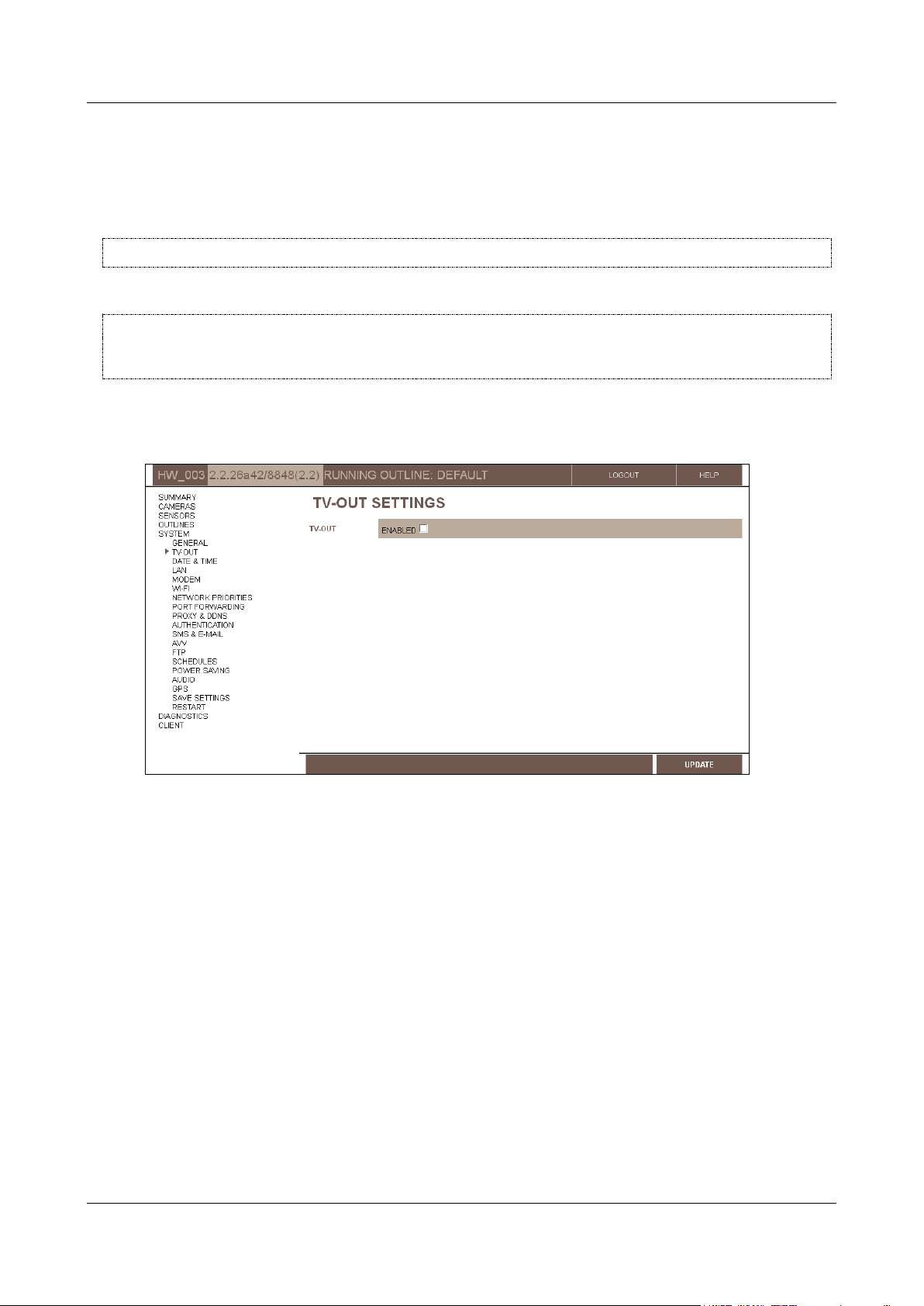
To enable a CCTV monitor connected to the Video Gateway unit:
1. In the Main Menu, under System, click TV-Out. The TV-Out Settings screen opens:
Figure 17: TV-Out Settings screen
2. Select Enabled. The fields required to configure the monitor display are added to the screen.
Configuring System Settings 25
SerVision Embedded Video Gateway System Guide
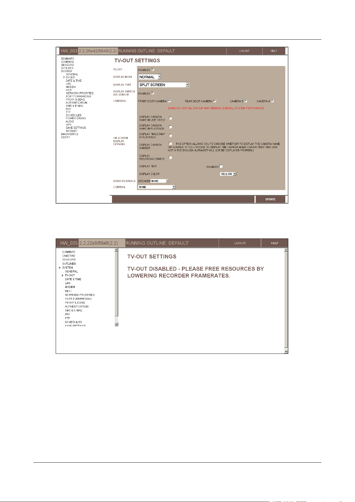
Figure 18: TV-Out settings displayed (MVG)
Note: TV-Out cannot be enabled if recording framerates are very high (see Advanced Recorder Settings,
page 106). In this case, if you attempt to enable TV-Out, a TV-Out Disabled message will be displayed:
Figure 19: TV-Out Disabled message
3. Configure the monitor as explained in the next sections (Configuring the Monitor to Display Video from the
Video Gateway, below, and Configuring the Monitor to Play Prerecorded Video, page 30).
Configuring the Monitor to Display Video from the Video Gateway
A CCTV monitor connected to the Video Gateway unit can be used to display live video from the unit in various
ways, as configured in the TV-Out Settings screen. If the monitor has a touch screen, or the supplied mouse is
connected to the unit, the display can be changed on the fly and recorded video can be played back.
Configuring System Settings 26
SerVision Embedded Video Gateway System Guide
Field
Description
Display type
Select the desired layout for the video display on the monitor:
Split Screen: Divides the screen so that video from all the
cameras is visible all the time
Full Screen – Camera #: Displays video from the specified
camera in full-screen mode
No Display: Does not display any live video; instead, only a menu
is displayed. The display can be controlled from the menu (if the
monitor has a touch screen or a mouse is connected to it).
Full Screen – Rotate: Loops through all of the cameras,
displaying each in full-screen mode for the number of seconds
specified under Rotate delay
Rotate delay
If you selected the Full Screen – Rotate display type, specify the number of
seconds you want the video from each camera to be displayed before it is replaced
with video from the next camera.
Note: This field only appears if the Full Screen – Rotate display type is selected.
NOTE: For information about viewing video from the Video Gateway unit on a connected CCTV monitor, see
Appendix A: Viewing Video on a CCTV Monitor (TV-Out), page 207.
To configure the CCTV monitor to display video from the Video Gateway:
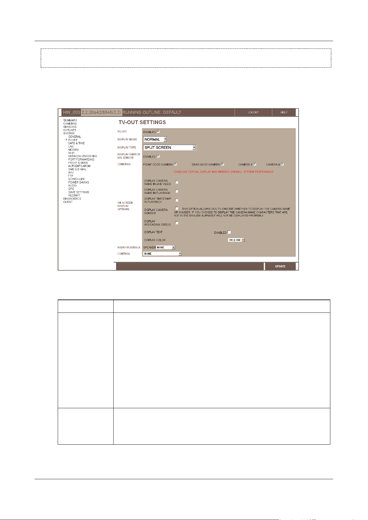
1. In the TV-Out Settings screen, under Display Mode, select Normal. The fields required to configure the
monitor to display video from the Video Gateway are added to the screen:
Figure 20: TV-Out settings for Normal display (MVG)
2. Fill in the fields as follows:
Configuring System Settings 27

SerVision Embedded Video Gateway System Guide
Field
Description
Display Switch Via
Sensor
Select this option if a switch is connected to the relevant sensor connector on the
unit (In6 on the HVG400; In4 on the MVG400, and UVG400; In1 on MVG200, CVG,
and CVG-M models), and you want to use the switch to cycle through the various
display types.
Note: This option is only fully activated if it is selected here and configured in the
appropriate sensor configuration screen (for HVG400, MVG400, or UVG400, the
Sensor 4 configuration screen; for MVG200, CVG, or CVG-M, the Sensor
configuration screen), as described under
Configuring a Sensor to Control CCTV
Display
, page 126.
Note: On MVG200, CVG and CVG-M models, this option should not be selected if the
sensor connector (In1) is used for an outline switch. For additional information,
please refer to the unit’s installation guide.
Cameras
Select the cameras that will be accessible via the monitor. Cameras that are not
selected do not appear in the monitor at all. Video from these cameras cannot be
viewed on the monitor and the cameras cannot be configured through the monitor.
Display Camera
Name in Live Video
Select this option if you want the name of the camera to be displayed in the camera
pane when live video is played on the monitor.
Note: Displaying names on the monitor requires extra system resources and may
impede performance.
Note: If the name of a camera contains characters from non-Latin alphabets such as
Hebrew or Arabic, or accented characters, those characters are not displayed
properly on the monitor. In this case, you can select both this option and Display
Camera Number (see below) in order to display the index of the camera (1, 2, 3,
or 4) instead of its name.
Display Camera
Name in Playback
Select this option if you want the name of the camera to be displayed in the camera
pane when recorded video is played on the monitor.
Note: Displaying names on the monitor requires extra system resources and may
impede performance.
Note: Recorded video can only be played on the monitor if touch or mouse support
is enabled (see step 6 below). Otherwise, this option has no effect.
Note: If the name of a camera contains characters from non-Latin alphabets such as
Hebrew or Arabic, or accented characters, those characters are not displayed
properly on the monitor. In this case, you can select both this option and Display
Camera Number (see below) in order to display the index of the camera (1, 2, 3,
or 4) instead of its name.
Display Timestamp
in Playback
Select this option if you want the date and time to be displayed in the camera pane
when recorded video is played on the monitor.
Note: Displaying timestamps on the monitor requires extra system resources and
may impede performance.
Note: Recorded video can only be played on the monitor if touch or mouse support
is enabled (see step 6 below). Otherwise, this option has no effect.
Display Camera
Number
If you chose to display the camera name for live and/or recorded video, select this
option to display the camera number instead of its name. This is particularly useful if
the name contains non-Latin characters that are not displayed properly on the
monitor.
Note: This option has no effect if neither Display Camera Name in Live Video
nor Display Camera Name in Playback is selected.
Configuring System Settings 28
SerVision Embedded Video Gateway System Guide
Field
Description
Display Recording
Status
Select this option if you want the recording status to be displayed at the bottom of
the screen at all times. The recording status indicates whether recording is taking
place as it should be, and, if it is, displays the current recording status of each
camera in the system. For additional information, see
Recording Status Display
,
page 235.
Text field
Hexadecimal
code field
Test Color
button
3. If you want any other text to be displayed on the monitor, such as your company name or an advertisement,
under Display Text, select Enabled. A text field is added to the screen. Enter the text you want to display in
the text field. The text will be displayed on the monitor at the bottom of the screen, in the center.
Figure 21: Text field
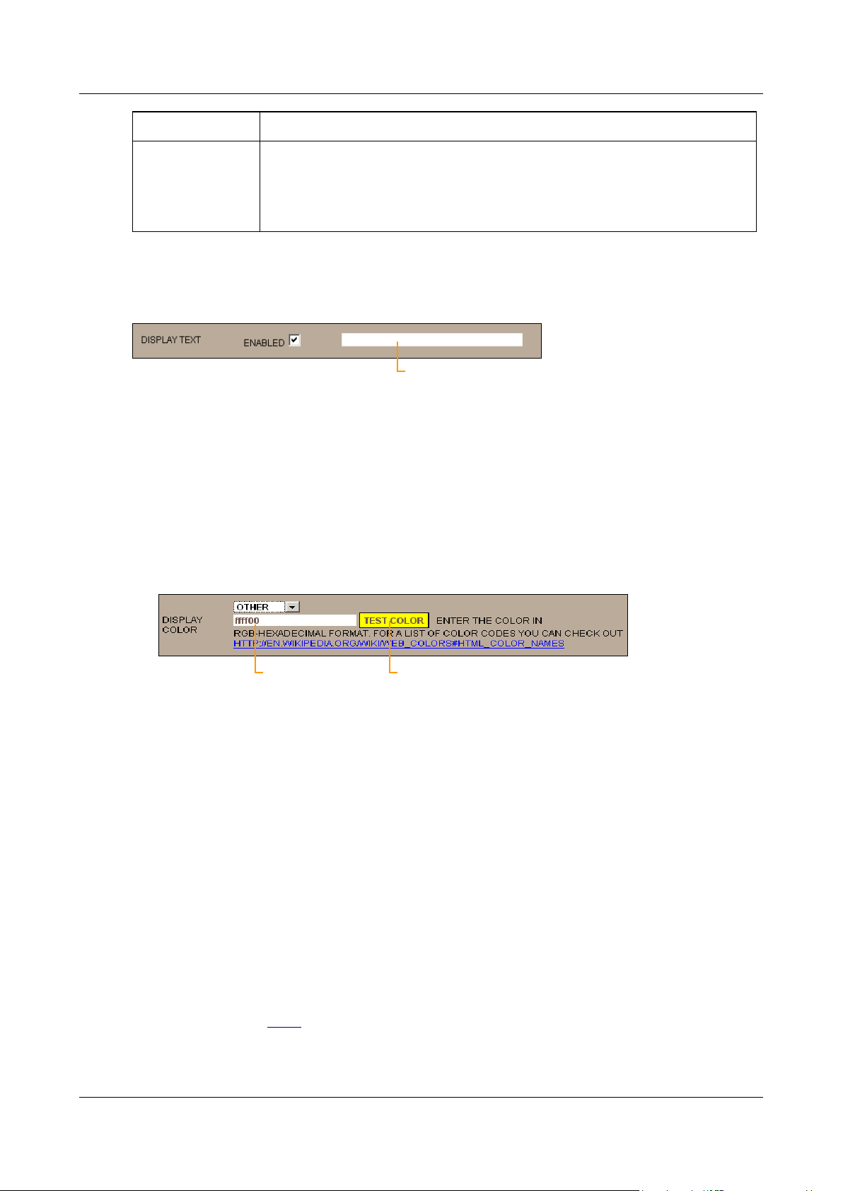
4. Under Display Color, select the color in which on-screen text should be displayed. You can choose one of
five preset colors or select any color you wish by specifying its RGB hexadecimal code, as follows:
To select one of the preset colors: from the dropdown list, select Yellow, Orange, Black, Blue, or Red.
To specify a hexadecimal code: from the dropdown list, select Other. The fields required to specify the
color are added to the screen. The hexadecimal code field displays the hexadecimal code of the currently
selected color. The code consists of three two-digit hexadecimal numbers, for the red, green, and blue
components of the color, respectively. The current color is displayed as the background to the Test Color
button.
Figure 22: Hexadecimal number field
Type the desired hexadecimal code into the field. To see what the color looks like, click Test Color.
Note: For more information about RGB hexadecimal codes, click the link below the fields.
5. Under Speaker, select one of the following audio playback options (for playback of recorded video):
None: Do not play attached audio when recorded video is played.
Internal: Play attached audio from the unit’s built-in internal speaker when recorded video is played.
External: Play attached audio from the external speaker plugged into Aout when recorded video is
played.
Note: This option only effects playback of recorded video streams that have audio attached (i.e., a microphone
attached to the Video Gateway is linked to the camera recording the video stream).
6. Under Control, select one of the following options:
None: Users cannot control the monitor display; video will be displayed in accordance with the selected
Display Type (see above). This option should be chosen if the monitor does not have a touchscreen, and a
mouse is not connected to the Video Gateway. You can also use it to disable the touch feature of a
touchscreen or to disable a connected mouse.
Configuring System Settings 29

SerVision Embedded Video Gateway System Guide
Note: If you select this option, skip to step 9.
Mouse: Enable control of the monitor display using the mouse connected to the Video Gateway.
Note: This option is not available for MVG, CVG, and CVG-M models.
Touchscreen type: If the monitor has a touchscreen, select the type of touchscreen from the list.
Note: Only the types of screens listed are supported. It is recommended to consult SerVision technical
support before purchasing a monitor with a touchscreen, to ensure that the protocol used by the monitor is
supported. If the touchscreen is not supported, video will be displayed in accordance with the selected
Display Type, but the touch controls will not work.
If you selected either Mouse or a type of touchscreen, the Screensaver field is added to the screen.
7. If you want a screen saver to be turned on when there is no user input (the touchscreen has not been touched or
the mouse has not been moved) for a period of time, under Screensaver, select Enabled. The fields required
to define the time period are added to the screen:
Figure 23: Screensaver settings
8. Under Timeout, specify the period of time that must pass without user input before the screensaver is
activated.
Under Hours, fill in the number of hours in the timeout period.
Under Minutes, fill in the number of minutes in the timeout period.
For example, according to the settings in the figure above, in which Hours is “0” and Minutes is “10,” the
screensaver is turned on whenever there is no user input for ten minutes.
9. Click Update, and then save the settings. They will be implemented after the unit is restarted (see Saving
Configuration Changes, page 156).
Configuring the Monitor to Play Prerecorded Video
A CCTV monitor connected to the Video Gateway unit can be used to play prerecorded video that is stored on the
unit, such as movies or ads. Only video in the Video Gateway's standard format, SMF, can be played. If you want to
use a CCTV monitor for this purpose, SerVision can provide you with a video-converter that you can use to convert
your video files to the required format. Once the video is converted, you can download the files to the Video
Gateway unit's storage medium.
NOTE: For information about converting video files to SMF format and downloading them to the Video
Gateway unit, please contact SerVision technical support.
When this feature is enabled, the CCTV monitor automatically plays all the SMF files that are stored on its storage
media in the location allocated for this purpose, one after the other, in a continuous loop. You must configure how
much of the storage medium is allocated for these files (in GB), as explained below. This is the maximum amount
of video data you can place on the storage medium for playing on the CCTV monitor. The amount you allocate will
no longer be available for recording video from on-site.
WARNING: Since enabling this mode causes the system to reallocate the space on the storage medium, all
recorded video stored on the Video Gateway when you enable this option is erased.
This feature requires a large amount of system resources. At times, the resources required may not be available
because they are being used for the other functions of the unit may, such as recording video and transmitting video
Configuring System Settings 30

SerVision Embedded Video Gateway System Guide
streams to clients. When this occurs, playing of video in the CCTV monitor is temporarily suspended. It resumes
automatically when the resources are once again available.
NOTE: For additional information about this option, please contact SerVision technical support.
To configure the CCTV monitor to play video from the Video Gateway:
1. In the TV-Out Settings screen, under Display Mode, select Content. The fields required to configure the
monitor to play the prerecorded video are added to the screen:
Figure 24: TV-Out settings for Content playback (MVG)
2. Under Disk Allocation for Content, select how many GBs of storage space to allocate to the prerecorded
video you want to play back in the CCTV monitor.
3. Click Update. A warning message appears, reminding you that this feature may take resources away from
other system functions.
Configuring System Settings 31

SerVision Embedded Video Gateway System Guide
Figure 25: Warning message
NOTE: When Content mode is enabled, this warning message appears every time you open the TV-Out
Settings screen.
4. In the message, click OK.
5. Open the Save Settings page. A warning message appears in the page, informing you that all existing
recording on the unit will be erased when you save the settings.
Figure 26: Warning message on Save Settings page
6. Select Save Changes to System.
Configuring System Settings 32

SerVision Embedded Video Gateway System Guide
7. In the Save Settings screen, click Save Changes to System. The unit stores the changes permanently, all
recorded video on the unit is erased, and the System Restart Page screen opens:
8. Click Restart System. The unit restarts, and the changes are implemented.
Setting the Unit Time
The unit has a built-in battery-backed clock that keeps track of the date and time even when the unit is turned off. It
is important to ensure that the time on the unit is accurate whenever the system is running; all video recordings
include timestamps that are derived from the unit's time, and playback relies on these timestamps. An inaccurate
clock can lead to misunderstandings when playing recorded video. Moreover, the unit will not record if the time on
it is invalid.
The clock can be set by manually synchronizing its time with the time on the PC on which the configuration utility
is running. This should be done when the system is first set up.
Like most clocks, the unit's clock has a tendency to drift slightly over time. Therefore, the time should be updated at
frequent intervals. The time can be updated manually at any time. The unit can also be configured to update its
clock automatically by connecting to an NTP time server at specified intervals. This option only works when the
unit has access to one or more NTP time servers, either public ones on the internet or locally-installed ones on the
LAN. Public NTP servers can be used free of charge and can be easily accessed when the unit has internet access.
MVG and CVG-M units can also be configured to update their clocks from GPS servers.
In addition to the time itself, the general time settings – time zone and daylight savings time (summer time) –
should always be configured correctly. The time zone and daylight-savings settings should be set correctly before
the clock is set. (After setting the time zone, be sure to click Update and restart the unit before manually updating
the time.) Daylight savings time can be activated manually or configured for automatic activation. When daylight
savings time is activated, the time on the unit clock is set one hour ahead of the time in the selected time zone.
To set the general time settings:
1. In the Main Menu, under System, click Date & Time. The Date & Time Settings screen opens:
Figure 27: Date & Time Settings screen (MVG)
Note: The current date and time recorded on the clock of the Video Gateway unit appear in the System Time
field.
Configuring System Settings 33

SerVision Embedded Video Gateway System Guide
Manual
Lets you activate and deactivate daylight savings time manually. When this option is
selected, the Enabled checkbox appears below the DST Control Type field. Select this
checkbox when daylight savings time begins, and clear it when daylight savings time ends.
Figure 28: Manual DST settings
Automatic
Lets you define a rule for the automatic activation and deactivation of daylight savings
time. For example, you can specify that daylight time should be activated on the last
Sunday of March. When this option is selected, the Start and End lines appear below the
DST Control Type field. In the Start line, specify the start date of daylight savings time;
in the End line, specify the end date.
Figure 29: Automatic DST settings
Automatic
Floating
Lets you specify the start and end dates of daylight savings time. When this option is
selected, four pairs of Start Date and End Date fields appear below the DST Control
Type field. Use them to define up to four daylight-savings-time periods (covering the next
four years).
Figure 30: Automatic-Floating DST settings
2. Under DST Control Type, select one of the following options:
Note: When daylight savings time is activated or deactivated automatically, the change is implemented at
midnight at the beginning of the selected day. For example, if you select Saturday, it is implemented at
midnight between Friday and Saturday.
Note: When daylight savings time is activated, the time on the unit clock is set one hour ahead of the time in
the selected time zone.
3. Under Time Zone, select the time zone in which the Video Gateway is located.
4. Click Update, and then save the settings. They will be implemented after the unit is restarted (see Saving
Configuration Changes, page 156).
Configuring System Settings 34

SerVision Embedded Video Gateway System Guide
Updating the Date and Time Manually
You should set the unit date and time manually when you first set up the system and when the Video Gateway has
not been used for a while. If you cannot or do not want to implement automatic time setting, you should also update
the time manually whenever the date and time are no longer accurate.
You can see the current date and time settings of the Video Gateway unit and of the PC in the Date and Time
Settings screen; the time on the Video Gateway unit is shown in the System Time field and the time on your
computer is shown in the PC Time field. Before you manually set the date and time on the Video Gateway unit,
make sure the date and time on the PC are correct and that the time zone and daylight-savings settings are the same
on the unit and on the PC.
The system stores time in GMT format. Because of this, it is very important to ensure that the time zone and
daylight savings time settings are identical on the PC and the Video Gateway. For example, if the PC is located in
New York, the system should be set to use GMT-5:00 (Eastern Time). If daylight savings time is in effect in New
York at the time, daylight savings time must be activated on the Video Gateway or the GMT conversion will not be
accurate and the time entered on the unit will not be correct.
Because time setting must be performed immediately to be accurate, the unit is automatically updated as soon as the
Sync time with PC button is clicked. (The unit should still be reset manually to fully implement the new time
setting.) If other configuration changes were made – including daylight savings time and time zone settings – it is
best to save the changes before using the sync feature (it is not necessary to restart the system). For additional
information about saving configuration changes, see page 156.
Under certain circumstances, resetting the time may make it impossible to view some recorded video, including
some video that is recorded after the time is set.
To update the time on the Video Gateway unit manually:
1. Make sure the date, time, and time zone on the PC are correct.
Note: The current date and time recorded on the clock of the Video Gateway unit appear in the System Time
field.
Note: If you have made other changes to the configuration, save them before continuing.
2. In the Date and Time Settings screen, click the Sync time with PC button. The date and time on the Video
Gateway unit are set to match the date and time on the PC, a confirmation message appears at the top of the
screen, and the System Restart Page is displayed with a confirmation message on the lower left of the
screen.
Configuring System Settings 35

SerVision Embedded Video Gateway System Guide
Sync Time confirmation message
Figure 31: System Restart Page after manual time updating
In two cases, the screen that is displayed may differ from the one in figure 31: if there were unsaved updates
when the time was synchronized, and if the clock was set ahead more than about 15 minutes. For information
about handling these cases, see page 36.
3. Click Restart System. The unit restarts, and the time on the unit is fully updated. You are automatically
logged out of the configuration utility, and a confirmation message appears:
Figure 32: Restart confirmation message
Note: To continue configuring the unit, click the link in the message and log into the configuration utility
again.
Note: If you do not reset the unit at this time, the time setting is partially implemented. The next time the unit
is reset, the time change is fully implemented.
Under normal circumstances, after you click the Sync time with PC button, the System Restart Page appears as
in figure 31. However, if you made changes to other configuration settings before you updated the time, and did not
yet save them on the unit (i.e., you clicked Update in one or more of the screens, but did not yet save the changes in
the Save Settings page), the System Restart page will include a message: “You have changes that need to be
saved. Click here to go to update page.”
Configuring System Settings 36

SerVision Embedded Video Gateway System Guide
Message
Figure 33: System Restart Page if the time was synchronized when there were unsaved changes
To save unsaved changes after the time was synchronized:
1. Click the message. The Save Settings page opens.
2. In the Save Settings page, click Save Changes to System, and then, in the System Restart page, click
Restart System.
In addition, if the unit clock was set ahead more than about 15 minutes during synchronization, instead of the
System Restart page, a message indicating that your configuration session has expired may appear. This does not
mean that the time was not reset correctly. However, you should still restart the unit to fully implement the update,
as follows:
To fully implement the time synchronization when the session expired during the process:
1. Log into the configuration utility again.
2. Navigate to the System Restart page and click Restart System.
Note: If you made changes to other configuration settings before you updated the time, and did not yet save
them on the unit (i.e., you clicked Update in one or more of the screens, but did not yet save the changes in
the Save Settings page), navigate to the Save Settings page, click Save Changes to System, and then, in
the System Restart page, click Restart System.
Configuring Automatic Time Setting
The Video Gateway can automatically keep its clock up to date by connecting to an NTP time server at specified
intervals. If you are configuring an MVG or a CVG-M, you can choose to use a land-based time server (on the
internet or on a local network) or GPS-based time synchronization for this purpose.
NOTE: If the Video Gateway unit is not connected to the internet most or all of the time, does not have GPS
support, and cannot connect to an alternative local time server, this feature will not keep the unit time
accurate.
The default configuration includes a number of internet time servers to which the Video Gateway can connect in
order to check the time. The unit automatically attempts to connect to a time server at regular intervals. Each time it
Configuring System Settings 37

SerVision Embedded Video Gateway System Guide
attempts to connect, it begins with the first server listed. If it fails to connect to that server, it tries the next on the
list, and so on. If you wish, you can replace any or all of the time servers on the list with other time servers, or add
additional time servers, to a maximum of ten servers. The list can include time servers on the internet and on a local
network.
For the MVG and the CVG-M, you can choose to use GPS-based time synchronization if GPS is enabled for the
unit (see Configuring GPS, page 88). When you choose this option, the unit clock is constantly updated via GPS.
To enable automatic NTP-based time setting:
1. In the Date & Time Settings screen, if the GPS Time field appears, clear the Enabled checkbox.
Note: The GPS Time field only appears for the MVG and CVG-M, and only if GPS is enabled in the General
System Settings screen (see Configuring GPS, page 88).
2. Under Update Frequency, select the interval between time checks, in hours.
3. Click Update, and then save the settings. They will be implemented after the unit is restarted (see Saving
Configuration Changes, page 156).
To enable automatic GPS-based time setting on the MVG or CVG-M:
1. In the Date & Time Settings screen, under GPS Time, select the Enabled checkbox.
2. Click Update, and then save the settings. They will be implemented after the unit is restarted (see Saving
Configuration Changes, page 156).
To disable all automatic time setting:
1. In the Date & Time Settings screen, if the GPS Time field appears, clear the Enabled checkbox.
2. Under Update Frequency, select Disabled.
3. Click Update, and then save the settings. They will be implemented after the unit is restarted (see Saving
Configuration Changes, page 156).
To specify other time servers when NTP-based time-setting is enabled:
1. In the Date & Time Settings screen, under Time Servers, add the IP addresses or hostnames of additional
time servers to the list, or replace existing IP addresses or hostnames with those of the time servers you want
to use, as required.
Note: Most time servers use port 123. If a time server you want to use uses a different port, you must specify
the port after the IP address or hostname. (Separate the address and the port with a colon (:). For example:
192.168.1.15:345)
2. Click Update, and then save the settings. They will be implemented after the unit is restarted (see Saving
Configuration Changes, page 156).
LAN Settings
The LAN settings define how the Video Gateway should connect to a cabled LAN – a local network to which it is
physically connected through an Ethernet network cable (connected to the Ethernet Out connector). These settings
are only relevant if the unit is connected to an external network via Ethernet cable. (For information about
connecting the unit to an external network, please refer to the unit’s installation guide.)
NOTE: MVG400 and UVG400 units have a built-in router. The LAN settings described here define how the
router connects to the external LAN, not how the unit connects to the internal LAN managed by its
router. The connection between the unit and the router is handled automatically by the system and does
not require any configuration (see Port Forwarding, page 55).
Configuring System Settings 38

SerVision Embedded Video Gateway System Guide
The LAN Settings screen is used to select a connection method – static IP or DHCP – for the Video Gateway to use
when connecting to a LAN. If a static IP is to be used, you must find out what IP to use, and what the appropriate
network settings are for the IP, before you begin: This information can be acquired from your network
administrator. If you want to be able to connect to the unit remotely through the LAN connection (to view video
and/or to modify the unit’s configuration) it is not generally recommended to use a dynamic IP address.
NOTE: If your network has a firewall, make sure that the port used by the unit (configured under General
System Settings; see Ports, page 17), and port 10000, are forwarded from the gateway (router) to
your Video Gateway for incoming communication.
To adjust the LAN settings:
1. In the Main Menu, under System, click LAN. The LAN Settings screen opens:
Figure 34: LAN Settings screen (MVG400)
2. For the MVG400 and UVG400, under Router, select Enable.
For the CVG and CVG-M, if the unit is connected to an external SerVision router, under Router, select
Enable. Do not select this option if the unit is connected to any other type of router.
Note: The Router field does not appear for HVG400 models.
3. If you want a dynamic IP address to be assigned to the unit by a DHCP server on the LAN, select the Enable
Dynamic IP (DHCP) checkbox.
Note: If this field is selected, you may not be able to access the unit remotely because the DHCP-assigned IP
may change from time to time.
Note: If this field is selected, the IP Address, Subnet Mask, Default Gateway, and DNS Server fields are
not relevant and are hidden.
4. If the unit will have a static IP address, clear the Enable Dynamic IP (DHCP) checkbox. The fields required
to configure the LAN settings are added to the screen.
Configuring System Settings 39

SerVision Embedded Video Gateway System Guide
IP Address
Specify the static IP address of the unit on the cabled LAN. The address should conform to
the standards of the LAN.
Subnet Mask
Modify the LAN subnet mask as necessary. The subnet mask should be the one the LAN
uses.
Default
Gateway
Fill in the IP address of the gateway through which the LAN connects to the internet.
If you do not know the IP address of the gateway, consult the network administrator or
your ISP.
Note: If this field is not filled in correctly, external network services will not be available
through this network. These include accessing the unit remotely (even through proxy and
DDNS services), SMS, e-mail notifications, and other services.
DNS
Fill in the IP address of the DNS server. A DNS server enables you to enter names instead
of IP addresses for the proxy and DDNS servers. The DNS server may be operated by your
internet provider (home installation) or on your network (some office installations).
If you do not know the IP address of the DNS server, consult the network administrator or
the ISP.
Note: If this field is not filled in correctly, you will not be able to specify IP addresses as
host names. For example, the address of the SMTP e-mail server will have to be defined as
IP numbers. In addition, DDNS will not perform updates if there is no valid DNS address.
Figure 35: Static IP settings
Fill in the fields as follows:
5. Click Update and then save the settings. They will be implemented after the unit is restarted (see Saving
Configuration Changes, page 156).
Modem
The Modem screen is used to configure the way the unit connects to a cellular network. Modem support in models
that use SerVision routers (MVG400, MVG200, and UVG) is slightly different from modem support in the
CVG-M, which has a built-in modem GSM and therefore does not need a router.
NOTE: If you use a cellular modem to make the Video Gateway accessible remotely, you may have to use a
SerVision proxy server to facilitate client connections to the unit. For additional information, see Proxy
and DDNS Settings, page 57.
Configuring System Settings 40

SerVision Embedded Video Gateway System Guide
IP in the cellular
network
Cellular connection
status
Additional
status
information
Video Gateway with Router
Modem settings configure the system to use the cellular modem connected to the unit’s USB port. Before you
configure the modem, ask your cellular supplier for the correct settings. When the modem is correctly configured,
the Video Gateway automatically attempts to establish a connection to the cellular network through it.
When the unit is connected to a cellular network, the Modem status displayed in the System Summary screen, in
the network settings, is “Connected,” and the IP address of the Video Gateway on the cellular network is displayed
there.
The system can be configured to automatically test the modem connection periodically once it is established. To do
this, the unit uses a network feature called LCP to send a test “ping” to the network. If the connection is functioning
properly, the network replies with a corresponding “ping” of its own. If the unit receives no response from the
network, it assumes the connection is no longer functional, and attempts to reconnect. In most cases, it is
recommended that this feature be enabled. This feature is not available on all cellular networks and, as such, it is
recommended that you contact your cellular provider for more information as to whether it should be used.
The unit does not have to be restarted before a cellular connection is established. This makes it possible to quickly
test the settings. Nevertheless, it is important to save the settings once they are correctly configured. Otherwise, the
settings will be erased when the unit is next restarted.
Configuring System Settings 41
Figure 36: System Summary screen showing the Video Gateway connected to a cellular network

SerVision Embedded Video Gateway System Guide
NOTE: Unless you have made other changes to the configuration that require a system restart, it is not
necessary to restart the system after the modem settings are saved on MVG and UVG400 units.
To configure the cellular modem connected to the unit:
1. In the Main Menu, under System, click Modem. The Modem Configuration screen opens:
Figure 37: Modem Configuration screen
2. Under Modem Configuration, select Enabled. The fields required to configure the modem are added to the
screen.
Figure 38: Modem Enabled (GSM settings)
3. Under Modem Type, select GSM if it connects to a GSM network, or CDMA if the modem connects to a
CDMA network. If you select CDMA, some of the fields are removed from the screen.
Configuring System Settings 42

SerVision Embedded Video Gateway System Guide
Field
Description
Username
If the cellular supplier requires a username, fill in the username.
Password
If the cellular supplier requires a password, fill in the password.
APN
Fill in the APN of the cellular network.
PIN Code
If the SIM card of the modem requires a PIN to establish a connection, select Use. The
PIN Code field is added to the screen.
Type the PIN code into the field.
Dial Number
The phone number that the modem should dial to connect to the internet via the GSM
cellular network. This number is normally *99# throughout the world.
Field
Description
Username
If the cellular supplier requires a username, fill in the username.
Password
If the cellular supplier requires a password, fill in the password.
Field
Description
LCP Echo
Select Enabled if you want the system to periodically test the network connection after it is
established (see page 41).
Use CHAP
Select Enabled if the cellular supplier uses CHAP authentication.
Figure 39: Modem Enabled (CDMA settings)
4. If you selected GSM, fill in the fields as follows:
5. If you selected CDMA, fill in the fields as follows:
6. Fill in the remaining fields as follows:
Configuring System Settings 43

SerVision Embedded Video Gateway System Guide
Field
Description
Router RST
on No Comm
If the connection to the cellular network is frequently lost, and selecting the Verify option
(see step 8 below) does not solve the problem, select this option. The system will
automatically check the router status from time to time, and if the router is not connected
to the network, it will restart the router.
Note: The unit continues to function while the router is restarted, so video recording and
Event detection are not interrupted.
Note: If you select this option, do not also select the Verfiy option.
Note: If you do not see this option in the Modem Configuration screen, you may need
to upgrade the router softare. For additional information, please contact SerVision technical
support.
Field
Description
Verification
Server
Specify the IP address or hostname of the server that the unit should ping in order to test
the connection. This can be any device on the network whose connection you want to test.
For example, if you want to ensure that the unit is connected to the internet, enter the URL
of a server that can only be accessed via the internet, such as www.google.com.
If the verification server does not respond to the ping, the unit attempts to reconnect to the
cellular network. It continues to try to connect periodically, at the interval specified, until it
succeeds.
Note: For additional information about the ping command, see
Ping
, page 173.
Interval
Fill in the frequency of the verification tests, in seconds.
7. Clear the Debug Mode checkbox unless you are instructed by SerVision technical support staff to select it.
8. If the connection to the cellular network is frequently lost or the quality of the connection is often low, select
Verify to configure the unit to test the cellular network connection periodically. The fields required to
configure this option are added to the screen.
Note: If Router RST on No Comm is selected, do not select this option.
Figure 40: Verification settings
Fill in the fields as follows:
9. Click Update. The settings are immediately implemented on the unit. If a modem is connected to the unit, and
the configuration settings are correct, the unit attempts to connect to the cellular network through the modem.
10. Save the settings to implement them permanently (see Saving Configuration Changes, page 156). It is not
necessary to restart the system.
Configuring System Settings 44

SerVision Embedded Video Gateway System Guide
CVG-M
The CVG-M has a built-in cellular GSM modem. The modem settings configure the CVG-M to connect to a
cellular network; the settings are implemented if a SIM card is installed in the unit. Before you configure the
modem, ask your cellular supplier for the correct settings for the SIM card you are planning to use.
NOTE: If the SIM card requires a PIN, configure the modem settings as described below before you insert the
SIM card into the unit. Otherwise, the unit may attempt to use the SIM card to connect to the network
with an incorrect PIN. Attempts to use the SIM with an invalid PIN may cause the SIM card to be
locked.
After you configure the modem settings, you must save them and restart the unit. From this point on, the unit
automatically attempts to establish a connection to a cellular network whenever it is not connected to a cable-based
network.
NOTE: For additional information about acquiring and setting up the hardware required for a cellular
connection, please refer to the unit's installation guide.
To configure the cellular modem:
1. In the Main Menu, under System, click Modem. The Modem Configuration screen opens:
Figure 41: Modem Configuration screen
2. Select Enabled. The fields required to configure the modem are added to the screen.
Configuring System Settings 45

SerVision Embedded Video Gateway System Guide
Field
Description
Username
If the cellular supplier requires a username, fill in the username.
Password
If the cellular supplier requires a password, fill in the password.
APN
Fill in the APN of the cellular network.
PIN Code
If the SIM card of the modem requires a PIN to establish a connection, select Use.
The PIN Code field is added to the screen.
Type the PIN code into the field.
Dial Number
The phone number that the modem should dial to connect to the internet via the
GSM cellular network. This number is normally *99# throughout the world.
Use CHAP
Select Enabled if the cellular supplier uses CHAP authentication.
Sense Proxy
In some cases, when a client connects to a CVG-M via a proxy server, the client can
connect to the unit, but it cannot open a video stream from the unit. If this occurs
frequently, it may mean the Video Gateway needs to free resources for video
streaming periodically. In this case, select this option. The unit will automatically
check if it needs to free resources, and, when it does, it will free them to make
them available for video streaming.
Figure 42: Modem enabled
3. Fill in the fields as follows:
4. Click Update, and then save the settings. They will be implemented after the unit is restarted (see Saving
Configuration Changes, page 156). At that time, if the unit is not connected to a cable-based LAN, it will
attempt to connect to the cellular network.
Configuring System Settings 46

SerVision Embedded Video Gateway System Guide
WiFi
WiFi settings can configure the system to connect to external access points (hotspots) or to function as an access
point for external devices.
NOTE: When the unit is configured to function as an access point, it cannot also connect via WiFi to other,
external access points.
Configuring the Unit to Connect to WiFi Access Points
You can specify up to ten WiFi access points to which you want the router to be able to connect. When WiFi is
enabled (and the unit is not configured to function as an access point; see Configuring the Unit to Function as an
Access Point, page 53), the router automatically establishes a connection to one of the specified wireless networks if
it is within range. If the access point is connected to the internet, the Video Gateway can use this connection to
connect to the internet in order to send and receive data.
When the unit is connected to a WiFi network, the WiFi status displayed in the System Summary screen, in the
network settings, is “Connected,” and the Video Gateway's IP in the wireless network is displayed.
Configuring System Settings 47

SerVision Embedded Video Gateway System Guide
IP in the WiFi
network
WiFi
connection
status
Additional
status
information
SSID of
WiFi
network
Figure 43: System Summary screen showing WiFi connected to access point
In order to connect to an access point, you must supply its service set identifier (SSID), which is essentially the
name of the wireless network.
In addition, many access points employ an encryption key to prevent unauthorized connections. If the access point
you specify requires an encryption key, you must specify the encryption method (WEP or WPA) and supply the key
if you want the unit to connect to the access point.
NOTE: Only WEP and WPA encryption methods are supported. The unit cannot connect to WiFi networks that
use other encryption methods.
The unit can save the SSIDs and settings of up to ten access points. If you specify more than one SSID, you can
prioritize them to indicate which ones you want the unit to connect to when more than one is in range.
You can configure access points even if no wireless card is connected to the unit, or when the access points are not
within range of the unit. When a wireless card is installed, you can use it to help you add access points that are in
range. The wireless card detects all of the access points that are within range of its current location and
automatically supplies the SSIDs of those access points.
By default, the unit is assigned a dynamic IP address in the wireless network when it connects to the access point. If
the unit will only need to use the wireless network for outgoing connections to the internet, this is enough. If you
need incoming access to the unit – that is, if you want to be able to access the Video Gateway remotely – you
should assign it a static IP address.
After the wireless settings are configured, the unit does not have to be restarted before a wireless connection is
established. This makes it possible to quickly test the settings. Nevertheless, it is important to save the settings once
they are correctly configured. Otherwise, the settings will be erased when the unit is next restarted.
Configuring System Settings 48

SerVision Embedded Video Gateway System Guide
NOTE: Unless you have made other changes to the configuration that require a system restart, it is not
necessary to restart the system after these WiFi settings are saved.
To configure the unit to connect to an access point:
1. In the Main Menu, under System, click WiFi. The WiFi Configuration screen opens. (This may take a
minute or two.)
Figure 44: WiFi Configuration screen
2. Under Turn WiFi Off, clear the Enabled checkbox.
3. If you will be configuring more than one SSID, under Random Selection of SSID, do one of the following:
Select Enabled if you want the unit to remain connected to the current access point as long as it can, even
if an access point with a higher priority level becomes available.
Clear Enabled if you want the unit to disconnect from lower-priority access points when higher-priority
access points become available.
4. Under Configured SSIDs, fill in the required information for each access point to which you want the unit to
be able to connect, as described in steps 5–9 below.
5. Under SSID, fill in the SSID of the access point.
Note: If a wireless card is connected to the unit, access points that are detected within range of the unit are
listed under SSIDs in Range at the bottom of the screen. Click Add SSID to add a detected SSID to the list of
configured SSIDs. (If a detected access point is in the list of configured SSIDs, it does not appear in the list of
detected access points.)
Configuring System Settings 49

SerVision Embedded Video Gateway System Guide
Field
Description
IP
Specify the static IP address of the unit in the wireless network. The address should conform
to the standards used in the wireless network.
Mask
Fill in the subnet mask used in the wireless network.
Gateway
Fill in the IP address (on the wireless network) of the gateway used for WAN or internet
access.
If you do not know the internal IP address of the gateway, consult the network administrator.
Note: If this field is not filled in correctly, external network services will not be available
through this network. These include accessing the unit remotely (even through proxy and
DDNS services), SMS and e-mail notifications, and other network services.
Figure 45: SSIDs in Range
6. If the access point requires an encryption key, specify the following:
Under Security, select the encryption method used by the access point (WEP or WPA).
Under Key, fill in the encryption key.
7. If you want to assign a static IP to the unit, clear the DHCP Enabled checkbox. The fields required to
configure the static IP are added to the screen.
Figure 46: Static IP settings
Fill in the fields as follows:
Configuring System Settings 50

SerVision Embedded Video Gateway System Guide
Field
Description
DNS
Fill in the IP address of the DNS server used by the access point. A DNS server enables you to
enter names instead of IP addresses for the proxy and DDNS servers.
If you do not know the IP address of the DNS server, consult the network administrator.
Note: If this field is not filled in correctly, you will not be able to specify IP addresses as host
names. For example, the address of the SMTP e-mail server will have to be defined as IP
numbers. In addition, DDNS will not perform updates if there is no valid DNS address.
Field
Description
Verification
Server
Specify the IP address of the server that the unit should ping in order to test the connection.
This can be any device on the network whose connection you want to test. For example, if
you want to check that the unit is connected to the WiFi network, enter the IP of a PC or
other device that is normally connected to the WiFi network. Alternatively, if you want to
ensure that the unit is connected to the internet, enter the URL of a server that can only be
accessed via the internet, such as the google server (173.194.113.179).
If the verification server does not respond to the ping, the unit automatically attempts to
reconnect to the access point and, failing that, to other configured access points.
Note: Enter the server address as an IP number, not as a hostname.
Note: For additional information about the ping command, see
Ping
, page 173.
Interval
Fill in the frequency of the verification tests, in seconds.
8. If you want the unit to test the connection to this access point periodically, select Verify. The fields required to
configure this option are added to the screen.
Figure 47: Verification settings
Fill in the fields as follows:
9. If you would like to change the priority level of the access point, click Move Up or Move Down as required.
10. Click Update. If a WiFi card is connected to the unit, the unit attempts to connect to the configured access
points. It connects to the first access point it can. “Connected” appears beside or below the SSID of the access
point to which the unit is connected.
Configuring System Settings 51

SerVision Embedded Video Gateway System Guide
Figure 48: Video Gateway connected to "SV-WIFI" access point
If Random Selection of SSID is enabled, the unit remains connected to that access point until the connection
is lost. If Random Selection of SSID is cleared, it disconnects from the access point if it can connect to a
higher-priority access point.
Note: In some cases, "Connected" may appear even if the Video Gateway has not successfully connected to
the network. This usually occurs when the signal is relatively weak, the WiFi antenna is not connected
securely to the unit, or the encryption key is incorrect. In these cases, the System Summary screen will list
WiFi as “Unavailable.” If the Video Gateway has an IP address in the System Summary screen (as in figure
43 on page 48), you can be sure that it is properly connected to the access point. Complete and accurate
information about the Video Gateway's network connections can also be seen in SVMultiClient, in the
Statistics window. For additional information, please refer to the SVMultiClient User Guide.
Note: If you install a WiFi card when the unit is running, you must restart the unit to access wireless networks.
11. Save the settings to store them permanently (see Saving Configuration Changes, page 156). It is not necessary
to restart the system.
Removing an Access Point from the List
If you do not want the Video Gateway to try to connect to an access point that is in the Configured SSIDs list, you
can remove it from the list.
To remove an access point from the list of Configured SSIDs:
1. In the WiFi Configuration screen, in the Configured SSIDs list, delete the SSID of the access point.
2. Click Update, and then save the settings (see Saving Configuration Changes, page 156). It is not necessary to
restart the system.
Turning WiFi Off
You can disable all WiFi services without removing the WiFi card from the USB connector or deleting any SSIDs
from the Configured SSIDs list. If the Video Gateway is configured to function as an access point (see Configuring
the Unit to Function as an Access Point, page 53), this functionality is also suspended when you disable the WiFi
services.
Configuring System Settings 52

SerVision Embedded Video Gateway System Guide
NOTE: When WiFi is turned off, all SSIDs in the Configured SSIDs list have the status "Not in Range," and
the list of access points that are within range does not appear. In the System Summary screen, and in
the statistics window of the SVMultiClient, the WiFi network status appears as "Connected, Disabled."
To turn all WiFi services off:
1. In the WiFi Configuration screen, under Turn WiFi Off, select Enabled.
2. Click Update, and then save the settings. They will be implemented after the unit is restarted (see Saving
Configuration Changes, page 156).
Configuring the Unit to Function as an Access Point
MVG and UVG400 units can be used as WiFi access points for other devices. This means that other WiFi-enabled
devices, such as PCs and smartphones, can connect wirelessly to the local network managed by the units' routers,
and, if the units are connected to the internet, these devices can connect to the internet through the local networks.
For example, if an MVG is installed in a vehicle and connected to the internet through a cellular network
connection, passengers in the vehicle could connect other devices to the MVG's network via WiFi and use the
MVG's internet connection to connect to the internet.
In order for a VG unit to function as an access point, you must assign an SSID to it and set its security settings.
Devices can connect to the access point in the same way that they would connect to any access point, using its SSID
and encryption key.
When the unit is configured to function as an access point, it cannot also connect via WiFi to other, external access
points. In this case, all the SSIDs in the list of Configured SSIDs appear as "Not in Range." In the System
Summary page, “WiFi” appears as disconnected. In the Statistics window of SVMultiClient, WiFi (WLAN)
appears as disconnected, and "AP," followed by the SSID of the Video Gateway, appear below it.
Figure 49: Statistics window in SVMultiClient showing WLAN as disconnected with AP below it when the
Video Gateway is functioning as an access point
To configure an MVG unit to function as an access point:
1. In the WiFi Configuration screen, under Enable WiFi as Access Point, select Enabled. The fields required
to configure the access point are added to the screen.
Configuring System Settings 53

SerVision Embedded Video Gateway System Guide
Field
Description
AP SSID
Enter the SSID of the unit's WiFi network (i.e., the name of the access point; see
page 48)
AP Authentication Type
Select the type of encryption to use (WEP, WPA, WPA2).
AP Key
Enter the encryption key to use (i.e., the key the user must use to connect to
the WiFi network).
Figure 50: Access-point configuration settings
2. Fill in the fields as follows:
3. Click Update, and then save the settings. They will be implemented after the unit is restarted (see Saving
Configuration Changes, page 156).
Network Priorities
If your system is configured to connect to more than one network at a time, it can use any of the available networks
for outgoing connections such as connecting to a proxy server or sending an e-mail notification. In this case, you
should rank the available networks to indicate which one you would prefer the system to use for outgoing
communications. For example, if the unit can connect to both a WiFi network and a cellular network, you would
probably want to give the WiFi network priority over the cellular network, because it is faster and cheaper to use. In
this case, the system would use the WiFi network whenever it was available; if it was not available, the system
would use the cellular network instead.
The unit does not have to be restarted before changes to the network priorities settings are implemented.
Nevertheless, it is important to save the settings once they are correctly configured. Otherwise, the settings will be
erased when the unit is next restarted.
NOTE: You can manually override the selected network priorities for specific types of outgoing
communications. When this is possible, the Use field appears in the relevant configuration screen. This
field allows you to select a specific network to use for proxy connections, DDNS connections, sending
e-mail notifications, and sending SMS notifications. For additional information, please refer to the
relevant section of this guide.
NOTE: Unless you have made other changes to the configuration that require a system restart, it is not
necessary to restart the system after the network priorities settings are saved.
Configuring System Settings 54

SerVision Embedded Video Gateway System Guide
To prioritize the network connections:
1. In the Main Menu, under System, click Network Priorities. The Network Priorities screen opens, and
displays the three networks – LAN, WLAN (WiFi), and Cell (Modem) – in their current order of priority (the
top network is ranked highest).
Figure 51: Network Priorities screen
2. To change the position of a network in the ranking, select the network type and then click Up or Down.
Figure 52: Moving a network up in the ranking
3. Click Update. The settings are immediately implemented on the unit.
4. Save the settings to implement them permanently (see Saving Configuration Changes, page 156). It is not
necessary to restart the system.
Port Forwarding
Port forwarding makes it possible for remote devices to access devices within the unit’s local network. Each device
that you want to make accessible to incoming connections is linked with a particular port of the router. To connect
to the device remotely, you use the external IP address of the router (the IP address of the Video Gateway on the
external network), and the assigned port number.
Configuring System Settings 55

SerVision Embedded Video Gateway System Guide
Field
Description
Port
The number of the port to assign to the device. You can choose any number in the range
1–65535 that is not already in use.
IP
The internal IP of the device
NOTE: Be sure to assign a static internal IP to the device before you set up port forwarding to it (see Appendix
C: Networks Managed by SerVision Routers, page 238)
To configure port forwarding for a device connected to the unit's router:
1. In the Main Menu, under System, click Port Forwarding. The Port Forwarding screen opens and displays
a list of the ports that are already open for remote access and the internal IPs of the devices to which they
provide access.
Note: The system and configuration ports of the unit in the router’s network (see Ports, page 17) are defined
automatically by the router and cannot be modified.
Figure 53: Port Forwarding screen
2. In the next available row in the table, fill in the fields as follows:
Figure 54: Adding a port
3. Click Update and then save the settings. They will be implemented after the unit is restarted (see Saving
Configuration Changes, page 156).
Configuring System Settings 56

SerVision Embedded Video Gateway System Guide
Proxy and DDNS Settings
Proxy services make it possible for clients to connect to Video Gateway units that cannot be accessed directly.
Dynamic DNS (DDNS) enables clients to connect to Video Gateway units that do not have fixed public IP
addresses.
A proxy server is used to enable client applications to connect to Video Gateway units like the Video Gateway
when the connection cannot be directly initiated by the client. Typically, this occurs when the Video Gateway
connects to the internet through the cellular network. It may also occur if the Video Gateway connects to the
internet through a cable-based connection that does not have a public IP address. The proxy server functions as an
intermediary that relays requests and data between the Video Gateway and clients. When you enable the proxy
service on a Video Gateway, the Video Gateway initiates a connection with the proxy server and registers with it
each time it connects to a network. Clients can then connect to the Video Gateway indirectly by connecting to the
proxy server. For additional information about proxy services in general and about proxy servers that are available
for use please contact your vendor.
DDNS is designed to facilitate internet connections to systems that use dynamic public IP addresses (see Appendix
B: LAN Settings, page 237). When you enable a DDNS on a Video Gateway, the Video Gateway is assigned a
name. The Video Gateway registers with the DDNS service each time it connects to the internet, and relays its
current public IP address to the service. Client applications connect to the Video Gateway by using its name rather
than its public IP address. The DDNS service ensures that the correct public IP address is linked to the name at all
times, even when the IP changes.
Three DDNS services are supported by the system: SV-DDNS (SerVision's DDNS service), No-IP, and DynDNS.
For information about the SV-DDNS service, consult your vendor. For information about the No-IP and DynDNS
DDNS services, consult their websites (www.no-ip.com and www.dyndns.com).
To modify the Proxy and DDNS settings:
1. In the Main Menu, under System, click Proxy & DDNS. The Proxy and DDNS Settings screen opens:
Figure 55: Proxy and DDNS Settings screen
2. If you are using a proxy for remote access, under Proxy, select Enabled. The fields required to configure the
proxy settings are added to the screen.
Configuring System Settings 57

SerVision Embedded Video Gateway System Guide
Use
MVG and UVG400:
Select the network connection to use to connect to the proxy server:
Any: The unit can use any available network connection; it will
connect using the highest priority connection available (as defined
under Network Priorities; see
Network Priorities
, page 54).
LAN: The unit will only use a LAN connection. If none is available, the
unit will not connect to the proxy server.
WiFi: The unit will only use a WiFi connection. If none is available,
the unit will not connect to the proxy server.
Modem: The unit will only use a Modem connection. If none is
available, the unit will not connect to the proxy server.
HVG400, CVG, CVG-M:
Not currently in use.
Host/IP
Fill in the IP address or hostname of the proxy server.
Port
Fill in the access port of the proxy server. (This port number is defined in the
configuration settings of the proxy server.)
Note: If Allow Only Encrypted is selected in the General screen, all video is
encrypted before it is transmitted to the proxy server. In this case, the port number
entered here should be the port for encrypted data. (This port number is defined in the
configuration settings of the proxy server.) Note that the proxy server decrypts the
encrypted video when it receives it. If you want encrypted video to be sent by the proxy
server to clients, you must select the next option, Encrypt Proxy Communication.
Encrypt Proxy
Communication
Select this option if you want the Video Gateway to encrypt all video it transmits to
proxy servers.
Figure 56: Proxy settings
Fill in the fields as follows:
3. If you are using a DDNS service, under DDNS, select Enabled. The fields required to configure the DDNS
settings are added to the screen.
Configuring System Settings 58

SerVision Embedded Video Gateway System Guide
Use
MVG and UVG400:
Select the network connection to use to connect to the DDNS server:
Any: The unit can use any available network connection; it will connect
using the highest priority connection available (as defined under
Network Priorities; see
Network Priorities
, page 54).
LAN: The unit will only use a LAN connection. If none is available, the unit
will not connect to the DDNS server.
WiFi: The unit will only use a WiFi connection. If none is available, the unit
will not connect to the DDNS server.
Modem: The unit will only use a Modem connection. If none is available,
the unit will not connect to the DDNS server.
HVG400, CVG, CVG-M:
Not currently in use.
Type
Select the type of DDNS service.
Note: If you select
No-IP
or
DynDNS
, the Username, Password, and Confirm Password
fields are added to the screen, and the Advanced field is removed from the screen.
Hostname
Fill in the hostname of the DDNS server.
If you are using either
No-IP
or
DynDNS
, these values should have been supplied to you when
you set up your account.
If you are using the SerVision
SV-DDNS
service, the default hostname is the Video Gateway's
default system name. This name is used when Use system name as hostname is selected.
You can modify this name as you wish. To do so, clear the Use system name as hostname
checkbox. A text field is added to the screen. Fill in the name you want to use. The name you
choose should not include any spaces or underscores. In addition, you should make sure the
name is unique. For example, you can include your name or the name of your company in the
hostname to ensure it is unique. The complete hostname on the SerVision SV-DDNS server
will be composed of the name you type plus .TVG.CC. For example, if you type
“JaneSmytheOffice,” the hostname on the server is JaneSmytheOffice.TVG.CC.
Note: Once DDNS is set up, changes to the server name will have no effect on the DDNS
settings.
Figure 57: DDNS settings
Fill in the fields as follows:
Configuring System Settings 59

SerVision Embedded Video Gateway System Guide
DDNS Server
Fill in the IP address or hostname of the SV-DDNS server.
DDNS Port
Fill in the access port of the SV-DDNS server.
Live Video
The user can connect to the unit through a client application and view live video.
Recorded Video
The user can connect to the unit through a client application and view recorded video.
Camera Control
The user can connect to the unit through a client application and control cameras using their
PTZ controllers.
Note: The Live Video permission must also be selected in order for the user to make use of
this feature.
Configuration
The user has full access to the unit’s configuration utility and can modify the configuration
settings.
4. If you are using either the No-IP or the DynDNS DDNS service, fill in the Username and Password fields.
The username and password should have been supplied to you by No-IP or DynDNS when you set up your
account there. Under Confirm Password, type the password a second time to ensure you typed it correctly.
Note: SerVision cannot provide support for problems related to the No-IP or DynDNS DDNS services. For
technical support, please contact the service providers.
5. If you are using the SV-DDNS service and you want to change the address of the DDNS server, select
Advanced. The fields required to specify the server are added to the screen.
Figure 58: Advanced SV-DDNS settings
Fill in the fields as follows:
6. Click Update, and then save the settings. They will be implemented after the unit is restarted (see Saving
Configuration Changes, page 156).
Authentication
Access to the system is controlled by username-password authentication. You can create up to ten users. For each
user, you can define a specific combination of system permissions. Users can be assigned any or all of the following
permissions:
By default, two users are defined:
A user with permissions for all of the system’s features. The default username for this user is svuser and the
password is servconf.
Configuring System Settings 60

SerVision Embedded Video Gateway System Guide
A user with all client permissions – live video, recorded video, and camera control – but no configuration
permission. The default username for this user is anonymous and the password is guest.
You can modify the default settings and add new users as necessary. It is recommended that you change the default
usernames and passwords of both of the default users.
NOTE: Multiple users can log into the system simultaneously using the same username and password.
To modify usernames and passwords:
1. In the Main Menu, under System, click Authentication. The Authentication screen opens. Each row in the
screen defines the settings for one user.
Figure 59: Authentication screen
2. In each row, define or modify the settings of one user, as necessary:
Under Username, specify the username of the user.
Under Password, specify the password for the username.
Under Confirm Password, specify the password a second time to ensure you entered it correctly.
Under Permissions, select the permissions you want the user to have.
3. Click Update, and then save the settings. They will be implemented after the unit is restarted (see Saving
Configuration Changes, page 156).
SMS and E-mail Notifications
You can choose to send an SMS or an e-mail to a predefined list of people whenever events of specified types are
detected.
Configuring System Settings 61

SerVision Embedded Video Gateway System Guide
Figure 60: E-mail event notification
If you opt to write-protect recorded video (see Advanced Recorder Settings, page 106), you can also choose to send
an e-mail warning message when the disk space allocated to a recorder is almost full or is entirely full.
Figure 61: Recorder almost full warning
In order to use the SMS functionality, you must set up an account with Clickatell (http://www.clickatell.com). In
order to send e-mails, you must have a valid SMTP e-mail account that can be used as the “sender” of the e-mail
messages.
NOTE: Web-based e-mail does not always support SMTP settings.
E-mail notifications and warnings contain standard messages that include the name of the unit and information
about the event or situation that caused the message to be sent. Depending on the notification settings of each
device, e-mail notifications of events may sometimes include snapshots of the first frame of the event. If full-sized
VGA or D1 recording is activated (see Advanced Recorder Settings, page 106), you can choose whether images sent
with e-mail notifications are sent as standard-sized images (SIF or CIF), or large images (VGA or D1). If AVV is
activated (see Automatically Uploading Video to an AVV Server, page 67), an image and a link to the uploaded
video are always included.
You can specify the text of SMS messages that are sent by defining a message template. The template can contain
any text you wish. It can also contain variables that will be replaced by the system with relevant values in the actual
message. For example, the message can include the name of the recipient, the time, and the name of the device that
triggered the event. For additional information, see SMS Message Templates, page 66.
Once you have configured the notification settings, you can test them by sending a sample notification. For
additional information, see Testing Notification Settings, page 67.
This section explains how to configure the settings that make it possible for the system to send notifications.
Messages are only sent if the device triggering an event – a camera, sensor, or activator – is configured to send
notifications of events or warnings about disk usage. For information on configuring a device to send notifications,
see the sections about configuring that type of device:
Video Motion Detection (VMD), page 96
Configuring Video Lost, page 102
Advanced Recorder Settings, page 106
Configuring Sensor and Activator Settings, page 119
Configuring System Settings 62

SerVision Embedded Video Gateway System Guide
To configure SMS and e-mail notification settings:
1. In the Main Menu, under System, click SMS & E-mail. The SMS and E-mail screen opens:
Figure 62: SMS and E-mail screen
2. Under SMS Message Template, modify the text of the message that should be sent to the SMS recipients on
the list, as necessary. The message can contain up to 45 characters, including spaces. It should not include
quotation marks of any kind (", ', or `).
Note: The message text can contain variables that are replaced by the system with relevant values in the actual
message. For example, the message can include the name of the device that triggered the event. For additional
information, see SMS Message Templates, page 66.
The default message includes the recipient’s name, the name of the Video Gateway unit, the name of the
device that triggered the event, and the time at which the event was triggered. If the message has been changed
from its default version, and you want to replace the current message text with the default text, click Restore
Default Template.
3. For each recipient of an SMS or e-mail message, under Recipients, click Add. A row is added to the list of
recipients.
Figure 63: New recipient row
Fill in the fields as follows:
Configuring System Settings 63

SerVision Embedded Video Gateway System Guide
Name
The name of the person who will receive an SMS or e-mail message when an event
occurs (up to 20 characters).
E-mail /
Phone number
Fill in the phone number or e-mail address of the recipient.
SMS: Enter the phone number in the international format, with no spaces. The number
is made up of the country code, the area code and the phone number.
Example: For the US phone number
212-555-1212, enter +12125551212.
E-mail: Enter the e-mail address.
Example: johns@demoserv.net
Image Size field
Note: To send both an SMS and an e-mail to the same person, list the person twice in the list of recipients; fill
in the SMS phone number in one of the listings, and the e-mail address in the other listing.
Figure 64: Recipients list
4. Under Image Size, select the size of the JPEG image that will be attached to e-mail notifications that contain
images. If the unit is configured to use VGA video resolution, you can choose either full-size VGA or the
smaller SIF. If the unit uses D1 video resolution, you can choose either full-size D1 or smaller CIF. For
additional information about video resolutions, see Video Resolution, page 18.
Figure 65: Image Size field
5. If you want to send SMS notifications, under SMS Connection Information, fill in the fields as follows:
Configuring System Settings 64

SerVision Embedded Video Gateway System Guide
Use
MVG and UVG400:
Select the network connection to use to connect to the SMS server:
Any: The unit can use any available network connection; it will connect
using the highest priority connection available (as defined under
Network Priorities; see
Network Priorities
, page 54).
LAN: The unit will only use a LAN connection. If none is available, the
unit will not connect to the SMS server.
WiFi: The unit will only use a WiFi connection. If none is available, the
unit will not connect to the SMS server.
Modem: The unit will only use a Modem connection. If none is
available, the unit will not connect to the SMS server.
HVG400, CVG, CVG-M:
Not currently in use.
Username
Fill in the username of your Clickatell account.
Password
Fill in the password of your Clickatell account.
API
Fill in the API ID of your Clickatell account.
Sender ID
Fill in the Sender ID that was assigned by Clickatell.
Use
MVG and UVG400:
Select the network connection to use to connect to the e-mail server:
Any: The unit can use any available network connection; it will connect
using the highest priority connection available (as defined under
Network Priorities; see
Network Priorities
, page 54).
LAN: The unit will only use a LAN connection. If none is available, the
unit will not connect to the e-mail server.
WiFi: The unit will only use a WiFi connection. If none is available, the
unit will not connect to the e-mail server.
Modem: The unit will only use a Modem connection. If none is
available, the unit will not connect to the e-mail server.
HVG400, CVG, CVG-M:
Not currently in use.
SMTP Server
Fill in the SMTP server of your e-mail account as they appear in your e-mail software
configuration.
SMTP Port
Enter the SMTP port number used to send e-mail messages.
Domain Name
Enter the domain name to insert in the
sender
address of the e-mail message. For
example, if you want the sender address to be alert@test.com, enter test.com.
Note: If you do not have an active Clickatell account, open one at http://www.clickatell.com.
Note: SerVision cannot provide support for problems related to the Clickatell service. For technical support,
please contact Clickatell.
6. If you want to send e-mail notifications, under E-mail Connection Information, fill in the fields as follows:
Configuring System Settings 65

SerVision Embedded Video Gateway System Guide
User Name
Enter the user name to insert in the
sender
address of the e-mail message. For example,
if you want the sender address to be alert@test.com, enter alert.
SMTP
Authentication
If the SMTP server requires authentication, select Enabled. The Username and
Password fields are added to the screen.
Username
Fill in the username of your e-mail account as it appears in your e-mail software
configuration.
Note: This field only appears if SMTP Authentication is enabled.
Password
Fill in the password of your e-mail account as it appears in your e-mail software
configuration.
Note: This field only appears if SMTP Authentication is enabled.
&S
The name of the sensor or VMD that triggered the event
Front Door
&U
The name of the Video Gateway unit
Bus-5478
&T
The time of the event
22 Feb 07 00:17:16
Figure 66: E-mail settings
Note: Internet mail accounts (e.g., Yahoo or MSN) are not supported. A list of free SMTP servers can be
found at http://www.e-eeasy.com/SMTPServerList.aspx.
7. Click Update, and then save the settings. They will be implemented after the unit is restarted (see Saving
Configuration Changes, page 156).
SMS Message Templates
The following codes can be included in SMS message templates:
The default message template is:
&S activated on &U at &T
If the Front Door sensor is triggered, John will receive the following SMS message from the Video Gateway:
Configuring System Settings 66

SerVision Embedded Video Gateway System Guide
Sensor (Front Door) ON activated on Bus-5478 at 22 Feb 07 00:17:16
The recipient name is set in each message to match the name of the recipient as it appears in the Recipient list
below the message template.
You can modify the default message to suit your requirements. For example, you could enter the following
message:
An event was detected: &S at &T
In this case, when the Front Door sensor is triggered, all the SMS recipients in the list will receive the following
message from the Video Gateway:
An event was detected: Sensor (Front Door) ON at 22 Feb 07 00:17:16
Testing Notification Settings
Once the event notification settings are configured, and the settings have been implemented on the unit (i.e., the
settings were saved and the unit was reset), you can test the SMS and e-mail settings to ensure that the notifications
are sent to the recipients you intended.
To send a test message to the notification recipients:
In the System Summary screen, under SMS & E-mail, click the Test E-mail button or the Test SMS
button. A sample message is sent to all of the recipients of the specified type of notification.
Note: If no recipients are defined for one of the types of notifications, the test button for that type of
notification does not appear.
Note: Test messages are sent based on the notification configuration settings that are currently defined on the
Video Gateway unit. If you make changes to the configuration, but have not yet saved them on the unit and
reset the unit, they will not be reflected in the test notifications that are sent.
Automatically Uploading Video to an AVV Server
You can configure the system to automatically upload recorded video of events from the Video Gateway unit to an
AVV (Alarm Video Verification) web server. Once the video has been uploaded, you can access the server via the
internet to view the video.
Video of an event can include a few seconds of video from immediately before the event was triggered ("prerecording") and a few seconds after the event ended ("post-recording"). You can configure the number of seconds
of pre- and post-recording to include. Note, however, that the pre-recording video may not be available for upload
because it may not have been recorded by the Video Gateway. This can occur if recording from the relevant camera
is by-event, and the pre-recording period defined for the camera is shorter than the pre-recording period specified
for AVV uploading. The recording settings of the camera are set in the Camera screen (see Configuring Video
Recording, page 105). For additional information, see Video Recording Settings, page 104.
If e-mail connection information is configured (see SMS and E-mail Notifications, page 61), e-mail notifications are
sent to the specified recipients both when the system begins uploading video to the AVV server and when the
system successfully completes the upload. The initial e-mail notification includes a picture of the first recorded
frame of the event and a link to the relevant video on the AVV server. The second e-mail is a text message that also
includes a link to the video on the AVV server. To access the video, you need only click the link in one of the emails. You can also access the video on the AVV server by navigating to the download site.
Configuring System Settings 67

SerVision Embedded Video Gateway System Guide
Figure 67: AVV notification e-mail – start of upload
Figure 68: AVV notification e-mail – upload completed
On the MVG and UVG400, video files are sent by the Video Gateway using the highest-priority network
connection available. (For information about prioritizing network connections, see Network Priorities, page 54.)
This section explains how to configure the settings that make it possible for the system to upload video to an AVV
server. Video is only actually uploaded if AVV is activated in the configuration of the device triggering an event – a
camera, sensor, or activator. For information on configuring a device to trigger automatic uploading of events to an
AVV server, see the sections about configuring that type of device:
Video Motion Detection (VMD), page 96
Configuring System Settings 68

SerVision Embedded Video Gateway System Guide
Server
Fill in the IP address or hostname of the AVV upload server.
Configuring Video Lost, page 102
Configuring Sensor and Activator Settings, page 119
NOTE: A list of devices that are configured to trigger AVV is displayed at the top of the AVV screen (see
figure 72, page 71).
To configure the settings of the AVV server:
1. In the Main Menu, under System, click AVV. The Alarm Video Verifications screen opens:
Figure 69: Alarm Video Verifications screen
2. Under AVV, select Enabled. The fields required to configure the AVV settings are added to the screen.
Figure 70: AVV screen expanded
3. Fill in the fields as follows:
Configuring System Settings 69

SerVision Embedded Video Gateway System Guide
Use Same Server for
Upload and Download
If the URL for uploading and downloading is the same, select this checkbox.
Otherwise, clear this checkbox. The Download Server field is added to the
screen.
Download Server
Fill in the IP address or hostname of the AVV download server. The URL must
include the network protocol (e.g.,
http
or
ftp
).
Note: This field does not appear if the Use Same Server for Upload and
Download is selected.
Port
Fill in the port used for FTP connections to the AVV server (usually 21).
Upload Path
Fill in the path of the FTP directory on the AVV server. The Video Gateway will
upload the video files to this directory.
Username
Fill in the username required to access the FTP directory on the AVV server.
Password
Fill in the password required to access the FTP directory on the AVV server.
Download Path
Fill in the path of the HTTP directory on the AVV server. You will download the
video files to your PC from this directory.
Maximum Size
Select the desired frame size for the downloaded video. If the unit is configured to use
VGA video resolution, you can choose on of the following:
QSIF: Small frame (160x120 pixels)
SIF: Medium-sized frame (320x240 pixels)
VGA: Large frame (640x480 pixels)
If the unit uses D1 video resolution, you can choose one of the following:
QCIF: Small frame (176x120 pixels for NTSC systems and 176x144 for
PAL systems)
CIF: Medium-sized frame (352x240 pixels for NTSC systems and
352x288 pixels for PAL systems)
D1: Large frame (704×480 pixels for NTSC systems and 704x576 pixels
for PAL systems)
4. Under Recorder Settings, do one of the following:
If you want to use the same recorder quality settings for the downloaded video as those used for recorded
video that is stored on the Video Gateway, select Use Default Settings. Then skip to step 6.
If you want to select different recorder quality settings, clear the Use Default Settings checkbox. The
fields required to configure the recorder settings are added to the screen.
Figure 71: AVV custom recorder settings
Note: Default recorder settings are set in the Camera screen. For additional information, see Video Recording
Settings, page 104; Advanced Recorder Settings, page 106.
5. Fill in the fields as follows:
Configuring System Settings 70

SerVision Embedded Video Gateway System Guide
Note: Large frame (VGA or D1) is available only if large-frame recording is activated for
one or more of the cameras connected to the Video Gateway. (See
Advanced Recorder
Settings
, page 106.)
For additional information about video resolutions, see
Video Resolution
, page 18.
Note: If you select a frame size that is larger than the frame size of the default recording
setting of a camera, the default setting is used and the value you specify is not
implemented. For example, if VGA is selected here, and recording for the camera is in
SIF, the uploaded video will be in SIF.
Note: This setting only affects the resolution of the video uploaded to the AVV server; it
does not affect the size of the image attached to the e-mail notification.
FPS
Fill in the required framerate for the recordings, in frames per second.
Note: If you specify an FPS value that is larger than the FPS value of the default
recording setting of a camera, the default setting is used and the value you specify is not
implemented.
KBPS
Fill in the required bitrate for the recordings, in kilobits per second.
Note: If you specify a KBPS value that is larger than the KBPS value of the default
recording setting of a camera, all of the default quality settings are used and the values
you specify for maximum size, FPS, and KBPS are not implemented.
Devices
configured to
trigger AVV
6. Under Pre-Recording, specify the number of seconds of video from immediately before the event was
triggered to include in the upload.
7. Under Post-Recording, specify the number of seconds of video from immediately after the event ended to
include in the upload.
8. Click Update, and then save the settings. The AVV option is added to the camera, sensor, and activator
screens. The changes will be implemented after the unit is restarted (see Saving Configuration Changes,
page 156).
Note: You can now configure devices to act as triggers for AVV. A list of devices that are configured to
trigger AVV is displayed at the top of the AVV screen.
Configuring System Settings 71
Figure 72: List of devices configured to trigger AVV

SerVision Embedded Video Gateway System Guide
Viewing the List of Files on the AVV Server
You can view a list of the files on the AVV server by navigating to the http directory on the server. The name of
each file indicates the device that detected the event, and the date and start-time of the event. For example:
Office_Security_VMD_(Back_Door)(2)_09_07_2007_20_43_51.svr
To view a list of the video files on the AVV server:
1. In the Address field of a browser, fill in the download address of the video. For example, if your AVV server
name is storage.servdemo.net, and the download path is /demo, enter
http://storage.servdemo.net/demo/
Figure 73: Address of download site
2. Press Enter. If the download directory requires authentication, a dialog box opens, requesting the username
and password.
3. Fill in the username and password, as required, and then click OK. A list of the files stored in the download
directory appears in the browser window.
Figure 74: List of files in the download directory
Viewing Video from the AVV server
To view the video that is stored on the AVV server, you download the video to a PC and then play it in
SVMultiClient.
To download and view a video file from the AVV server:
1. If you received an e-mail notification of the event, click either the image or the link in the e-mail.
Configuring System Settings 72

SerVision Embedded Video Gateway System Guide
link
Figure 75: E-mail notification with video link
Otherwise, navigate to the download site though the browser as described above, and click the required file in
the list.
If the site requires authentication, a dialog box opens, requesting the username and password.
2. Fill in the username and password, as required, and then click OK. A dialog box opens, and asks what to do
with the video file.
3. Select Save. A file selector dialog box opens.
Configuring System Settings 73

SerVision Embedded Video Gateway System Guide
4. Navigate to the location on your PC in which you want to save the video clip file, and then click Save. The file
is saved in the selected location.
5. Open SVMultiClient.
6. Play the video clip file in SVMultiClient in one of the following ways:
Drag the downloaded file to a camera pane in SVMultiClient.
In the Tools menu, select Play Downloaded Video. Navigate to the file, select it, and then click in a
camera pane.
The video clip is played in the camera pane.
Note: For additional information about playing video files in SVMultiClient, please refer to the relevant user
guide.
Disabling AVV
Once AVV uploading has been enabled, you can disable it as follows:
To disable AVV uploading:
1. Ensure AVV is disabled for all cameras and sensors connected to the Video Gateway unit.
Note: To do this, in the AVV screen, check the list of devices for which AVV is activated. The list appears
below the Enabled field if AVV is activated for any devices (see figure 72). For each device in the list,
disable AVV in the configuration screen of the device. (For information about how to do this, see the
following: on VMD settings, see page 96; on video lost settings, see page 102; on sensor and activator
settings, see page 119.)
2. In the Main Menu, under System, click AVV. The Alarm Video Verifications screen opens.
3. Under AVV, clear the Enabled checkbox. The fields used to configure the AVV settings are removed from
the screen.
Note: This checkbox is disabled if AVV is enabled in any VMD or video lost settings, or in the settings of any
sensor or activator.
4. Click Update, and then save the settings. The AVV option is removed from the camera, sensor, and activator
screens. The changes will be implemented after the unit is restarted (see Saving Configuration Changes,
page 156).
FTP Server Settings
You can configure the system to automatically upload snapshots from the Video Gateway unit to an FTP server.
This option provides an additional way to back up images of events in real time. It is especially useful when
bandwidth limitations make uploading video streams over cellular connections impractical.
Snapshots can be uploaded either at specified intervals, in response to an event, or both. For example, you could
configure the Video Gateway to transmit snapshots of all events triggered by Sensor #1, at intervals of 15 seconds,
and, in addition, to transmit snapshots from all the cameras every 30 minutes.
This section explains how to configure the system to automatically upload snapshops from all cameras at specified
intervals and how to configure the settings that enable the system to upload snapshots of events. In order for
snapshops of events to be uploaded, you must also configure the settings of the devices that trigger the events.
Snapshots of events are only actually uploaded if FTP is activated in the configuration of a device triggering an
event – a camera, sensor, or activator. For information on configuring a device to trigger automatic uploading of
event snapshots to an FTP server, see the sections about configuring that type of device:
Video Motion Detection (VMD), page 96
Configuring System Settings 74

SerVision Embedded Video Gateway System Guide
Server
Fill in the IP address or hostname of the FTP server.
Port
Fill in the port used for FTP connections to the FTP server (usually 21).
Configuring Video Lost, page 102
Configuring Sensor and Activator Settings, page 119
To configure the settings of the FTP server:
1. In the Main Menu, under System, click FTP. The FTP Download configuration screen opens:
Figure 76: FTP Download configuration screen
2. Select the Enabled checkbox. The fields required to configure the FTP server settings are added to the screen.
Figure 77: FTP Download enabled
3. Fill in the fields as follows:
Configuring System Settings 75

SerVision Embedded Video Gateway System Guide
Username
Fill in the username required to access the FTP directory on the FTP server.
Password
Fill in the password required to access the FTP directory on the FTP server.
JPG Upload Interval
Select how frequently snapshots
of events
should be transmitted to the FTP server.
When FTP is activated for a sensor, snapshots from cameras associated with the
sensor will be uploaded this frequently.
Note: The resolution of the snapshots is the same as the resolution of the recorded
video of eafch camera (see
Video Recording Settings
, page 104).
Automatic Image
Upload
Select how frequently snapshots should be transmitted from cameras (routinely, not
in response to events), or select Disabled if you do not want any snapshots to be
transmitted in this way.
Resolution
Select the resolution for the snapshots that are uploaded automatically.
4. Click Update, and then save the settings. The changes will be implemented after the unit is restarted (see
Saving Configuration Changes, page 156).
Schedules
Schedules allow you to configure the unit to automatically switch the running outline at specified times. You can set
up standard repeating schedules for routine time periods, such as regular work weeks or the summer months. You
can also define special schedules for holidays, both repeating holidays (e.g., New Years Day) and non-repeating
holidays (e.g., a presidential visit or the opening ceremony of the Olympics).
The schedule is only implemented by the system if the following conditions are met:
Multiple outlines are defined for the system (see Defining Alternate Outlines, page 149)
Schedule-triggered outline-switching is activated in the General System Settings screen (see General
System Settings, page 17)
To configure the schedule:
1. In the Main Menu, under System, click Schedules. The Schedules screen opens. If schedule-triggered
outline switching is not activated in the General System Settings screen, Inactive appears in parentheses
after the name of the screen. In this case, you can configure the schedule, but it will not be implemented unless
you activate schedule-triggered outline switching.
Configuring System Settings 76

SerVision Embedded Video Gateway System Guide
Schedule
grid
User-defined
holidays
(if any)
Outline-
attachment
controls
Figure 78: Schedules screen (inactive)
2. Select Enabled. The schedule grid and its controls are displayed.
Figure 79: Schedules enabled
The upper part of the screen contains the schedule grid. Below it are controls that allow you to attach specific
outlines to particular days and times in the grid. Below these, user-defined holidays appear, if any are defined.
Initially, the schedule grid contains a row for each day of the week and a column for each hour of the day.
This grid defines the routine schedule for regular work weeks. Each cell in the grid contains two colored
rectangles (see figure 80 below). Each of these rectangles represents a half hour – half of the time represented
by the entire cell. The color of the rectangle indicates which outline it represents.
The key to the color-coding of the outlines appears below the grid. For example, in figure 80 below, the
Default outline is represented in the grid by a red rectangle, the Parking Lot outline by a blue rectangle, the
Out of Service outline by a green rectangle, and the Office Closed outline by a gray rectangle. Thus, the top-
left cell in the grid says that the Default outline should run from midnight to 12:30 am, and the Out-of-Service
outline should run from 12:30 am to 1:00 am.
Configuring System Settings 77

SerVision Embedded Video Gateway System Guide
Key to color-
coding
Cell
representing
one hour
Figure 80: Color-coded schedule
3. Follow the instructions below to create a basic, repeating weekly schedule and to add holidays to the schedule.
Configuring a Standard Weekly Schedule
This section explains how to set up a basic, repeating weekly schedule of outline implementation.
To define the basic weekly schedule:
1. In the color-coding key, click the name of the outline you want to assign to one or more time slots in the
schedule grid. A colored rectangle representing the selected outline is displayed below the key area, under
Selected Outline, and the name of the outline is displayed below this. For example, in the figure below, the
selected outline is Default, represented by the red rectangle.
Configuring System Settings 78

SerVision Embedded Video Gateway System Guide
Selected
outline
Border
Figure 81: Color-coded schedule
2. If you want to apply the outline to the entire week’s schedule, click Set all schedules to currently selected
outline. All of the rectangles in the schedule grid are switched to the color representing the selected outline.
3. If you want to apply the outline to specific day of the week, click the name of the day in the schedule grid. All
of the rectangles in the row are switched to the color representing the selected outline.
4. If you want to apply the selected outline to a rectangular area of the schedule grid (containing multiple
rectangles), do the following:
Make sure the Change Multiple Times checkbox is selected.
Click one corner of the rectangular area. A border appears around the rectangle.
Figure 82: Rectangle with border
Configuring System Settings 79

SerVision Embedded Video Gateway System Guide
Click the diagonally opposite corner of the rectangular area that you want to mark. The selected outline is
applied to the entire rectangle.
Figure 83: Clicking the diagonally opposite corner of the area
Note: The entire schedule grid, representing full 24-hour days, may not be visible at one time on your screen.
Use the horizontal scrollbar at the bottom of the screen to move the display to the right or left so that you can
see the relevant times of day.
5. If you want to apply the selected outline to individual half-hour time slots, do one of the following:
With the Change Multiple Times checkbox selected, double-click the rectangle representing the time
slot.
With the Change Multiple Times checkbox cleared, click the rectangle representing the time slot.
The rectangle is displayed in the color representing the selected outline.
6. Repeat steps 1–5 as necessary for each type of outline you want to apply to a time slot in the schedule.
7. Click Update, and then save the settings. They will be implemented after the unit is restarted (see Saving
Configuration Changes, page 156).
Defining Holiday Schedules
Holiday schedules are essentially exceptions to the standard weekly schedule. When you define a holiday, you can
choose to apply an existing day’s schedule to it. For example, you can apply the Sunday schedule to Independence
Day. Alternatively, you can create a new day’s schedule and apply the new schedule to one or more holidays. To do
this, you add a row to the schedule grid. For example, you could add a row called Business Holiday, define a
schedule for it, and then create a holiday called Independence Day to which you apply the Business Holiday
schedule (see Defining a New Schedule Row, page 83).
Holiday schedules can overlap. For example, if you create a holiday schedule for the first week of July, and another
holiday schedule for July 4th, the two schedules both apply to July 4th. In this case, the system creates a hierarchy of
schedules:
Shorter time periods are given precedence over longer time periods.
Non-repeating schedules are given precedence over repeating schedules.
Repeating holiday schedules are given precedence over the standard weekly schedule.
Thus, in the example above, the July 4th will schedule will be implemented on July 4th, and the schedule for the first
week of July will be implemented on the other days of the week.
To define a holiday:
1. In the Schedules screen, in the Holidays section, click Edit Holidays.
Configuring System Settings 80

SerVision Embedded Video Gateway System Guide
Edit
Holidays
Figure 84: Edit Holidays
The Holidays screen opens. The screen displays the schedule grid at the top (it is not editable here), and
below it, a list of the holidays that are already defined (if any).
Configuring System Settings 81

SerVision Embedded Video Gateway System Guide
Name
The name of the holiday, e.g.,
New Years Day
.
Start Date
The date of the first day of the holiday.
End Date
The date of the last day of the holiday. If the holiday only lasts one day, this is the same as
the start date.
Figure 85: Holidays screen
2. Click Add Holiday. A blank New Holiday section opens.
Figure 86: New Holiday section
3. Fill in the fields as follows:
Configuring System Settings 82

SerVision Embedded Video Gateway System Guide
Repeating
If the holiday occurs every year on the same date(s), select this checkbox.
If the holiday occurs on different dates every year, or is only taking place once, clear this
checkbox.
Valid On
The days of the week on which the holiday schedule is applicable. For example, if a Jazz
festival is scheduled for all of the Sundays in July, you could select Sunday. The holiday
schedule would be implemented only on the Sundays of the month of July.
Day
Select the name of the row in the schedule grid to implement on the holiday. For example, in
the Jazz festival scenario, if you select Saturday, the Saturday schedule would be applied on
all of the Sundays in July.
Note: If none of the existing schedules in the grid are appropriate for the holiday, you can
create a new row in the grid, as explained below. (The new row must be added in the
Schedules screen before it can be selected in the Holidays screen; once it is added, you can
select it in the Holidays screen in this dropdown list.)
Holiday added
to schedule
4. Click Update. The holiday schedule is updated. It will be implemented after you save the changes and restart
the system.
5. In the Main Menu, click Schedules. The Schedules screen opens. The holiday you defined appears in the list
of holidays at the bottom of the screen.
Figure 87: Holiday added to the schedule
Defining a New Schedule Row
In addition to the standard rows for the days of the week, you can create custom schedule rows that can be
implemented on holidays. For example, you could create a special row with a schedule that is to be applied only on
New Years Day.
To define a new schedule (row):
1. In the Schedules screen, below the schedule grid, click Add Row. A new row is added to the grid.
Configuring System Settings 83

SerVision Embedded Video Gateway System Guide
Name
updated
Name
New row
Add Row
button
Figure 88: New row in schedule grid
2. In the text field, modify "New Schedule" to define a name for the schedule.
Figure 89: Naming a new row
3. Click Update. The name of the row is updated.
Figure 90: Row name updated
Configuring System Settings 84

SerVision Embedded Video Gateway System Guide
Speaker
Select one of the following:
None: Disable both speakers.
Internal: Enable the internal speaker. (If an external speaker is
connected to Aout, it is disabled.)
External: Enable the external speaker. (The internal speaker is
disabled.)
Both: Enable both the internal speaker and the external speaker.
(The same audio stream will be played on both speakers at the
same time.)
Note: This field controls the use of the speakers to play sound that is transmitted
from a client device. Even if one or both of the speakers is disabled here, they can
still be used to play audio when a CCTV is connected to the Video Gateway. See
4. Follow the instructions under Configuring a Standard Weekly Schedule, page 78 to select the outlines to
implement in each time slot.
Note: To assign the new schedule to a holiday, click Edit Holidays to open the Holidays screen. Follow the
instructions above (see Defining Holiday Schedules, page 80) for configuring the holiday. The new schedule
appears in the holiday configuration section in the Day dropdown list.
Audio Settings
Audio settings enable and configure the speakers and microphone, as follows:
Audio Out settings: Enable internal and external speakers, and control the volume of the speakers. When the
speakers are enabled, remote users can speak into a microphone on a client device and be heard through the
unit's speakers on-site. (SVMultiClient, and most of the cellular client-applications support this feature.)
Audio In settings: Enable the microphone and control its volume. When a microphone is connected and
enabled, audio from the site can be heard along with live and recorded video.
To configure audio settings:
1. In the Main Menu, under System, click Audio. The Audio Settings screen opens:
2. Fill in the fields as follows:
Configuring System Settings 85

SerVision Embedded Video Gateway System Guide
Configuring a CCTV Monitor (TV-Out)
, page 25.
Note: On the HVG400, even if the internal speaker is enabled here, it can still be
turned off by flipping down the Mute switch on the rear of the unit.
Internal Speaker
Volume
Set the output volume for the unit’s built-in speaker, as explained under
Configuring
Microphone and Speaker Volume
, below.
Input Volume Ch 1 /
Input Volume Ch 2
Set the input volume for microphones connected to the unit, as explained under
Configuring Microphone and Speaker Volume
, below.
Note: On CVG and CVG-M models, only channel 1 is supported.
Note: On the HVG400, if the Which input to use? field appears, the unit only
supports one microphone. Select the audio channel to which the microphone is
connected from the dropdown list, and then set the input volume for that
microphone as described below.
0 1 2 3 4 5 6 7 8 9 10
Reduced volume No change Increased volume
3. Click Update, and then save the settings. They will be implemented after the unit is restarted (see Saving
Configuration Changes, page 156).
Note: Input volume settings are implemented immediately if you select Update Now. However, they are only
saved on the unit after you click Update and save the settings.
Configuring Microphone and Speaker Volume
The volume of attached microphones and of the internal speaker can be digitally increased or decreased by the
Video Gateway. Microphone volume can be modified to optimize the sound level of audio that is played by client
software. Internal speaker volume can be adjusted to suit the location of the Video Gateway unit and the needs of
those on-site.
You can choose from 11 levels of amplification. Level 5 means the volume is not modified at all. Levels 0 through
4 cause the volume to be reduced (the smaller the number, the greater the reduction); levels 6 through 10 cause it to
be amplified (the greater the number, the greater the amplification). Level 6 is generally optimal for the internal
speaker, level 9 for passive microphones, and level 5 for active microphones.
You can test the volume settings as you configure them by connecting to the Video Gateway using a client
application. Volume levels can be adjusted for testing purposes without resetting the Video Gateway unit.
Configuring Internal-Speaker Volume
You can optimize the internal-speaker volume settings by testing them as you configure them.
To configure the volume of the internal speaker:
1. Make sure someone is near the Video Gateway to listen to sound being transmitted from the speaker.
2. Using a client application that can transmit audio to a Video Gateway (SVMultiClient and some of the cellular
client applications), connect to the Video Gateway.
3. Speak into the microphone of the client device and check with the listener to find out if the volume is
appropriate. If it is not, adjust the settings as described below until they are satisfactory.
4. In the Audio Settings screen, under Internal Speaker Volume, select a volume setting.
Configuring System Settings 86

SerVision Embedded Video Gateway System Guide
Update Now
Figure 91: Speaker volume settings
5. Click Update Now. The volume settings are updated on the Video Gateway immediately
Figure 92: Update Now button
Note: All of the settings on the page are saved when you click Update Now. The volume settings are
implemented immediately, and the changes to the other settings are implemented after the unit is restarted (see
Saving Configuration Changes, page 156). If you modify the volume settings and click the Update button in
the lower-right corner of the screen, the volume settings are not implemented until the unit is restarted.
6. Repeat steps 3–5 as necessary until the optimal volume setting is selected.
7. Click Update, and then save the settings.
Configuring Microphone Volume
You can optimize the microphone volume settings for a particular client by testing the microphone settings as you
configure them.
To configure the volume of a microphone:
1. Open the client application for which you want to optimize the settings (e.g., SVMultiClient), connect to a live
video stream that is linked to the microphone, and listen to the sound. If the volume needs adjustment, adjust it
as explained in the following steps.
2. In the Audio Settings screen, under Audio In, select a volume setting for the microphone. (For HVG400,
MVG400, and UVG400 models, which have two microphone connectors, “CH1” sets the volume of the
microphone connected to Ain1, and “CH2” sets the volume for Ain2).
Figure 93: Microphone volume settings (HVG400, MVG400, UVG)
Figure 94: Microphone volume settings (MVG200, CVG, CVG-M)
3. Click Update Now (see figure 92 above). The volume settings are updated on the Video Gateway
immediately.
Configuring System Settings 87

SerVision Embedded Video Gateway System Guide
Note: All of the settings on the page are saved when you click Update Now. The volume settings are
implemented immediately, and the changes to the other settings are implemented after the unit is restarted (see
Saving Configuration Changes, page 156). If you modify the volume settings and click the Update button in
the lower-right corner of the screen, the volume settings are not implemented until the unit is restarted.
4. In the client application, listen to the audio from the video stream that is linked to the microphone.
5. Repeat steps 2–4 as necessary until the optimal volume setting is selected.
6. Click Update, and then save the settings.
GPS
GPS makes it possible to track the location of an MVG or CVG-M unit by means of the unit’s built-in GPS
receiver. When GPS is enabled on an MVG or CVG-M unit, the unit uses the built-in GPS receiver to check its
location at specified intervals. Whenever you are connected to the unit through the SVMultiClient or the
SVControlCenter client application, the location data that is received is automatically sent to the client. You can
then use the client to view the last detected location of the unit on a map. (For additional information about viewing
the unit's location on a map, and tracking the route taken by the unit, please refer to the SVMultiClient User Guide
and the SVControlCenter Guide.)
If you choose to record GPS data, you can use SVMultiClient or SVControlCenter to see the path that was taken by
the unit before it reached its last detected location. Recorded data is stored on the unit until the allocated disk space
is filled; then, the oldest data is overwritten by the newest data. The unit can store a great deal of GPS data. For
example, the MVG400 can store over one million GPS data points – approximately 2 months’ worth of location
data when the data is retrieved every 5 seconds.
Configuring GPS
If you have a server that can receive GPS data, MVG and CVG-M units can be configured to send the data to that
server at specified intervals. Alternatively, you can send the data to a device connected to the serial port (the
RS232/485 connector) of the Video Gateway unit (for additional information about this option, please consult your
vendor), or configure SVControlCenter to download it to its database for later use (see the SVControlCenter User
Guide).
GPS data can be sent in one or more of the following syntaxes. These syntaxes are part of the NMEA (National
Marine Electronics Association) standard that defines the data required to process a GPS location. The available
syntaxes are:
RMC: A modified version of Recommended Minimum sentence version C that includes some additional
information that is not included in the standard NMEA definition, such as the name of the sending unit. Please
consult your vendor for a complete description of this sentence.
GGA sentences: Standard GGA sentences
GLL: Sentences that are compatible with the syntax used by the Galooli fleet-management system (for
additional information about this system, see http://www.galooli.com/solutions/galooli-fleet/)
Once the GPS data is received by your NMEA server or a device connected to the serial port, you can use it as you
wish – to display in a map, monitor vehicle locations and possible deviations from the intended route – or store the
data for future use.
NOTE: SerVision does not provide any software for handling NMEA data that is transmitted to an NMEA
server. You must acquire and set up any required software on your own.
Configuring System Settings 88

SerVision Embedded Video Gateway System Guide
Field
Description
GPS Frequency
Specify how often the unit records its location, in seconds. Recommended value: 5.
Note: Because GPS location recording requires system resources, it is not recommended
to increase the frequency. While one check every five seconds is not sufficient for
navigation via GPS, it provides ample information for tracking purposes.
GPS Recording
Select this option to record the results of each GPS location check. This option must be
selected it you want to be able to see the route followed by the vehicle, or see where the
vehicle was when a particular event occurred, in SVMultiClient.
Note: Clearing this option does not free disk space for other uses.
Field
Description
RMC to server
Select this option if you want to send GPS data in RMC syntax to an NMEA server.
To configure the GPS settings:
1. In the GPS Settings screen, under GPS, select Enabled. The fields required to configure the GPS settings are
added to the screen:
Figure 95: GPS settings
2. Fill in the fields as follows:
3. If you want to send GPS data to a server or a device connected to the serial port, under Send GPS Data to
Server, select Enabled. The fields required to configure this option are added to the screen.
Figure 96: Send GPS Data to Server settings
Note: Whenever this option is enabled, GPS recording is automatically activated and cannot be deactivated.
4. Fill in the fields as follows:
Configuring System Settings 89

SerVision Embedded Video Gateway System Guide
Field
Description
RMC to serial
Select this option if you want to send GPS data in RMC syntax to a device connected to
the serial port of the Video Gateway unit. The data is sent at 4800 baud, 8 bits, no
parity, one stop bit (8N1).
GGA to server
Select this option if you want to send GPS data in GGA syntax to an NMEA server.
GGA to serial
Select this option if you want to send GPS data in GGA syntax to a device connected to
the serial port of the Video Gateway unit. The data is sent at 4800 baud, 8 bits, no
parity, one stop bit (8N1).
GLL
Select this option if you want to send GPS data to a Galooli server.
ID
If you selected GLL, enter the Galooli server ID.
Server address
If you opted to send RMC, GGA, or GLL data to a server, fill in the IP address or
hostname of the server.
Port
If you opted to send either RMC or GGA data to an NMEA server, fill in the port used to
by the server to receive NMEA data.
Sending
frequency
If you opted to send RMC, GGA, or GLL data to a server, specify how often the data
should be transmitted to the server, in seconds. Recommended value: 30.
Note: This value should be a multiple of the GPS Frequency value, and should not be
higher than the GPS Frequency (i.e., the Sending Frequency should not be set to a
smaller number of seconds than the GPS Frequency). If it is, the GPS Frequency is
actually set to equal the Sending Frequency.
Sending
frequency ignition off
If you opted to send GPS data to a server, and the Video Gateway is configured to
continue working after the vehicle ignition is turned off (either for a limited period of
time or indefinitely; see page 22), specify how often the data should be be transmitted
to the server when the ignition is off.
RMC history
If you chose to send RMC data, specify how much data should be stored for sending
later if the unit fails to send the data to the RMC server.
Erasing Recorded GPS Data
Recorded GPS data is normally stored on the unit's storage media until it is over-written by newer data. You can
also erase all GPS data from the unit manually.
To erase all recorded GPS data from the unit's storage media:
In the System Summary screen, under GPS, click Erase GPS Recordings. The recordings are erased.
Figure 97: Erase GPS Recordings
Note: The Erase GPS Recordings button only appears if GPS recording is enabled in the General System
Settings screen (see Configuring GPS, page 88).
Configuring System Settings 90

SerVision Embedded Video Gateway System Guide
Configuring Camera Settings
The Camera screens are used to configure the cameras connected to the Video Gateway unit. Settings include the
name of the camera; the desired brightness, contrast, and saturation; pan-tilt-zoom (PTZ) settings; audio settings;
video-motion-detection (VMD) settings; video-lost settings; and recording settings.
About Brightness and Contrast Settings
Brightness and contrast settings affect the camera and not just the display in the client interface. The settings
defined in the Camera screens are the default settings for video streams from the specified camera. When the video
stream is displayed in the client, these settings can be modified. This makes it possible for you to fine-tune the
settings while you are viewing the stream.
Modifications that are implemented in the client affect all live and recorded video from the relevant camera until the
Video Gateway unit is reset. To implement them permanently, they must be saved in the unit's configuration. To
save settings that are modified in a client application, you must log into the configuration utility and update the
settings there, as described below.
NOTE: Changes to brightness and contrast settings affect the camera directly, and are thus reflected in all
displays of live video from that camera from the time they are implemented. Similarly, video that is
recorded from the camera after the changes are implemented is also affected. The brightness and
contrast settings that are optimal for a particular monitor may not display as well on other monitors or
screens. Therefore, care should be taken when changes are made, and, furthermore, it may not be
advisable to save the modified settings on the unit in every case.
Configuring Video Cameras
The Camera Summary screen summarizes the current settings of each camera in the system, and provides links to
the camera configuration screens, in which the camera settings can be modified.
Figure 98: Camera Summary screen
Each camera in the system is configured in its own configuration screen. The camera configuration screens are
accessed from the Camera Summary screen.
Configuring Camera Settings 91

SerVision Embedded Video Gateway System Guide
NOTE: For information about the Erase Recordings and Set Recording Disk Size to Default options, see
Erasing Recorded Video, page 113. For information about the Restore Recording Settings to Default
option, see Restoring Default Recording Settings, page 110.
To open the Camera Summary screen:
In the Main Menu, click Cameras.
To configure a camera:
1. In the Main Menu, under Cameras, click the camera (e.g., Camera 1 to configure the camera plugged into
Vin1). The relevant Camera configuration screen opens:
Figure 99: Camera configuration screen
2. Select the Enabled checkbox. The fields required to configure the camera settings are added to the screen.
Configuring Camera Settings 92

SerVision Embedded Video Gateway System Guide
Description
Type a name for the camera (up to 20 characters). Each of the cameras must have a
different name.
The camera names are used to identify the camera in client applications.
Note: If the Video Gateway will be working in conjunction with an SVBackup server, use
only English characters in the name.
Embedded
Text
If you want an identifying label to be included in each frame of video that is displayed in a
client application, type the text of the label.
You can include the variables &C and &S in the text where you want to insert the camera
name and system name. For example, if the camera name is "Front Door" and the system
name is "Bus2045," type "&C camera on &S," and the label embedded in each frame would
say "Front Door camera on Bus2045."
Figure 100: Camera enabled
Note: If Enabled is not selected, the camera cannot record and will not appear in client applications.
3. Fill in the fields as follows:
Configuring Camera Settings 93

SerVision Embedded Video Gateway System Guide
Brightness
Adjust the default brightness of the camera. Range: 1–100. These values are used when the
Video Gateway unit is started.
Note: You can also adjust the brightness in the client or in a CCTV monitor (with the
touch/mouse enabled) as you view the video stream (see page 91 ).
Contrast
Adjust the default contrast of the camera. Range: 1–100. These values are used when the
Video Gateway unit is started.
Note: You can also adjust the contrast in the client or in a CCTV monitor (with the
touch/mouse enabled) as you view the video stream (see page 91 ).
Saturation
Adjust the default saturation of the camera. Range: 1–100. Higher saturation produces more
vivid colors.
Note: Changes to brightness, contrast, and saturation are implemented immediately when Update is clicked.
4. If the camera has PTZ features, and you want to use them to control the camera remotely through a client
application, under Camera Control (PTZ), select Enabled. Then follow the instructions below (Configuring
PTZ, page 95).
5. Under Audio, select one of the following:
None: Do not link any audio to the video from this camera.
Channel 1: Link the audio from the microphone connected to Ain1 to the video from this camera.
Channel 2: Link the audio from the microphone connected to Ain2 to the video from this camera
(HVG400, MVG, and UVG400 only).
Note: In HVG400 units that only support one microphone, you will either see Channel 1 or Channel 2 in the
dropdown list, depending on which one was activated. For additional information, see the description of the
Input Volume field (page 86).
If you selected None, skip to step 8.
If you selected either Channel 1 or Channel 2, audio from the selected microphone is available whenever you
view live video in a client application. In addition, the fields required to configure recording of audio with
recorded video from this camera are added to the screen, and a message appears indicating that audio
recording is enabled. This means that audio from the selected microphone is incorporated with all video
recorded from the camera.
Figure 101: Audio recording settings
Figure 102: Audio-recording-enabled message
6. In the audio-recording-enabled message, click OK.
Configuring Camera Settings 94

SerVision Embedded Video Gateway System Guide
Protocol
Select the communication protocol used by the camera for PTZ control.
Note: Consult the camera documentation or the camera vendor for this information.
7. If you do not want audio to be incorporated with the video recorded from the camera, under Audio
Recording, clear the Enabled checkbox.
Note: The Audio Quality field is not currently in use. All audio recordings have medium quality.
Note: If recording is not activated, this checkbox cannot be cleared.
8. If you want to use the Video Gateway’s VMD features to detect and respond to motion in the camera’s field of
view, under Motion Detection (VMD), select Enabled. Then follow the instructions below (Video Motion
Detection (VMD), page 96).
Note: Be aware that on PTZ-controlled cameras each change of the camera position is interpreted by the VMD
system as an event.
9. Configure the unit's response to interruptions in the transmission of the video signal from the camera to the
unit as described below (Configuring Video Lost, page 102).
10. Configure the camera’s recorder as described below (Video Recording Settings, page 104).
11. Click Update. Changes to brightness, contrast, and saturation are implemented immediately. Save the settings
to implement them permanently. Save the settings and restart the unit to implement all other changes (see
Saving Configuration Changes, page 156).
Configuring PTZ
This section explains how to configure the pan-tilt-zoom (PTZ) controls of cameras that support these features.
Once the controls are configured, the camera can be aimed and zoomed remotely using any of the client
applications.
NOTE: For information about connecting the PTZ controller to the Video Gateway unit, please refer to the
unit’s installation guide.
To configure pan-tilt-zoom controls (PTZ) in cameras that support these features:
1. In the Camera configuration screen, under Camera Control (PTZ), select Enabled. The fields required to
configure the PTZ settings are added to the screen:
Figure 103: PTZ settings
2. Fill in the fields as follows:
Configuring Camera Settings 95

SerVision Embedded Video Gateway System Guide
Baud Rate
Select the baud rate used by the camera for PTZ control.
Note: Consult the camera documentation or the camera vendor for this information.
Note: The other connection parameters required by the Video Gateway are:
one start bit, one stop bit, no parity
, and
8-bit
. If the camera uses different parameters,
please contact your vendor.
Connection
Type
Select the type of connection that is used for the PTZ controls – RS232 or RS-485.
Note: Consult the camera documentation or the camera vendor for this information.
Note: If multiple PTZ cameras that use the RS485 connection type are connected to the
Video Gateway unit, they must all use the same protocol.
Camera ID
If the camera is connected using RS485, specify its ID number.
Note: This number must correspond to the camera ID that is set on the camera. Consult the
camera documentation for information about setting the camera ID. If multiple PTZ cameras
using the RS485 connection are connected to the Video Gateway unit, they must have
distinct camera IDs.
Video Motion Detection (VMD)
When Video Motion Detection (VMD) is enabled, the Video Gateway automatically checks the field of view (FOV)
of the camera for changes. When changes are detected, the Video Gateway triggers a VMD event. You can
configure the VMD itself, and the event notifications that are generated when VMD events are triggered.
About VMD Regions
The FOV is divided into regions, and the relative sensitivity of the motion detection can vary from region to region.
For example, if a computer monitor in the FOV of the camera causes motion detection events to be triggered
unnecessarily, you can choose to mark the region of the monitor for low sensitivity, or even no motion detection,
while the rest of the FOV would have high sensitivity. In addition, you can completely black out regions from the
FOV if you do not want them included in the video images at all.
If the camera is connected to the Video Gateway, and regions are enabled, the Camera configuration screen shows
the current FOV of the camera. Regions that are included in motion detection are marked with a colored x: blue for
low sensitivity, green for medium sensitivity, and red for high sensitivity. Regions that are not included in motion
detection are not marked, and regions that are not included in the video images at all are marked with a black x on a
white background.
NOTE: If VMD is enabled, but regions are not, middle sensitivity is applied to the entire FOV.
NOTE: If the camera is not connected to the Video Gateway, a blank tan image is displayed. It is
recommended that you select the regions for inclusion in VMD when you can see an actual image.
About VMD Event Settings
A VMD event starts when motion is first detected and ends when there is no motion. However, in many cases what
is seen by the human eye as one event can be interpreted by the VMD system as a series of motions with idle
periods. When this occurs, a single motion event is broken into a series of short events. On the other hand, a motion
event as detected by the VMD system can be exhaustingly long, such as a full day in a busy shop. In this case, we
would prefer to break it down into a number of shorter events.
Configuring Camera Settings 96

SerVision Embedded Video Gateway System Guide
To solve these two problems, VMD event detection can be configured to control the length of events using the
following parameters:
Debounce: The interval between the end of motion as detected by the unit and the time when the event is
defined as ending
Maximum length: The maximum length of a single event
Separate events are defined when motion is not detected for a specified debounce interval. For example, if the
interval is 15 seconds, event A ends when motion is not detected for 15 seconds, and event B begins if motion is
detected again after more than 15 seconds have elapsed. If less than 15 seconds pass at the end of event A before
additional motion is detected, event A is extended to include the additional motion.
Separate events are also defined when the maximum event length is reached. For example, if the maximum length
of an event is 30 minutes, new events are generated every 30 minutes even if motion was detected without
interruption during the entire period.
Consider, for example, a camera that is set up in a train station. During peak hours, there is usually constant motion.
During off hours, lengthy intervals between motion events are common. The debounce interval is 30 seconds, and
the maximum event length is 1800 seconds (30 minutes). During peak hours, event-triggered recording generates
continuous recording because VMD events are constantly detected. However, the video is divided into 30-minute
events, making it easy to check the video to see what happened during a particular time range. During off-peak
hours, events are typically much shorter, and recording is not continuous.
About Responses to VMD Events
You can configure the unit to respond to VMD events in any or all of the following ways:
Upload video of the event to an AVV server on the internet (see Automatically Uploading Video to an AVV
Server, page 67). If e-mail notification recipients are defined in the SMS and E-mail screen, an e-mail
message is sent to all the recipients when the VMD event begins and a second e-mail is sent when the video is
successfully uploaded and is available for downloading by users. The e-mail notification includes a link to the
video file on the server and a picture of the event. (Note that the file transfer starts at the end of the VMD
event to ensure that it encompasses the entirety of the event.)
Upload snapshots of the event to an FTP server on the internet (see FTP Server Settings, page 74).
Send VMD event notifications to the SMS and/or e-mail recipients defined for the system (see SMS and E-
mail Notifications, page 61). E-mail notifications can optionally include a picture of the event, and, if AVV is
activated, a link to video of the event.
Turn an activator on or off.
Move any PTZ camera connected to the Video Gateway that supports presets to a preset location.
These actions can be implemented when the event begins, when it ends, or both.
Configuring VMD Settings
This section explains how to configure VMD settings for a camera.
To configure video motion detection (VMD):
1. In the Camera configuration screen, under Motion Detection (VMD), select Enabled. The fields required to
configure the VMD settings are added to the screen:
Configuring Camera Settings 97

SerVision Embedded Video Gateway System Guide
Figure 104: VMD settings
2. If you want to define the level of sensitivity of the motion detection that is implemented in the field of view
(FOV), and perhaps specify different levels of sensitivity for different regions of the FOV, under Regions,
select Enabled. Otherwise, skip to step 8.
The fields required to define sensitivity levels and regions are added to the screen, and, if the camera is
connected to the unit, the current FOV is displayed:
Figure 105: Region sensitivities in the FOV
Note: To update the snapshot of the camera’s FOV, click Reload Snapshot.
Note: If the camera is not connected to the Video Gateway, the FOV is blank.
3. Click the sensitivity level you want to apply to a region or regions of the FOV. The selected level appears
below the list under CURRENT. For example, in the figure above, MEDIUM SENSITIVITY is selected.
Note: The following region marks can be used:
Configuring Camera Settings 98

SerVision Embedded Video Gateway System Guide
Mark
Description
Blue x
Low VMD sensitivity
Green x
Medium VMD sensitivity
Red x
High VMD sensitivity
None
No motion detection
Black x on white background
Region blacked: no video capture
Border
4. If you want to set the entire FOV to the specified sensitivity level, click the relevant sensitivity level, and then
click Set all regions. The xs marking the entire FOV are colored, or removed, accordingly.
5. If you want to apply the current sensitivity level to a rectangular area of the FOV (containing multiple region
markers), do the following:
Make sure the Change Multiple Times checkbox is selected.
Click one corner of the rectangular area. A border appears around the region.
Figure 106: FOV with border around selected marker
Click the diagonally opposite corner of the rectangular area. The current sensitivity level is applied to the
entire rectangle.
Configuring Camera Settings 99
 Loading...