

Page 1

Switched Rack Power
Distribution Unit
Installation and Operations Manual
Firmware Version 7.0
Page 2

Instructions
This symbol is intended to alert the user to the presence of important operating and maintenance (servicing) instructions in
the literature accompanying the appliance.
Dangerous Voltage
This symbol is intended to alert the user to the presence of un-insulated dangerous voltage within the product’s enclosure that may be
of sufficient magnitude to constitute a risk of electric shock to persons.
Protective Grounding Terminal
This symbol indicates a terminal that must be connected to earth ground prior to making any other connections to the equipment.
Life-Support Policy
As a general policy, Server Technology does not recommend the use of any of its products in the following situations:
life-support applications where failure or malfunction of the Server Technology product can be reasonably expected to cause
failure of the life-support device or to significantly affect its safety or effectiveness.
direct patient care.
Server Technology will not knowingly sell its products for use in such applications unless it receives in writing assurances satisfactory
to Server Technology that:
the risks of injury or damage have been minimized,
the customer assumes all such risks, and
the liability of Server Technology is adequately protected under the circumstances.
The term life-support device includes but is not limited to neonatal oxygen analyzers, nerve stimulators (whether used for anesthesia,
pain relief or other purposes), auto-transfusion devices, blood pumps, defibrillators, arrhythmia detectors and alarms, pacemakers,
hemodialysis systems, peritoneal dialysis systems, neonatal ventilator incubators, ventilators (for adults or infants), anesthesia
ventilators, infusion pumps, and any other devices designated as “critical” by the U.S. FDA.
Notices
301-0113-1 Rev U (052016)
Copyright © 2005-2016 Server Technology, Inc. All rights reserved.
1040 Sandhill Drive
Reno, Nevada 89521 USA
All Rights Reserved
This publication is protected by copyright and all rights are reserved. No part of it may be reproduced or transmitted by any means or
in any form, without prior consent in writing from Server Technology.
The information in this document has been carefully checked and is believed to be accurate. However, changes are made
periodically. These changes are incorporated in newer publication editions. Server Technology may improve and/or change
products described in this publication at any time. Due to continuing system improvements, Server Technology is not responsible for
inaccurate information which may appear in this manual. For the latest product updates, consult the Server Technology web site at
www.servertech.com. In no event will Server Technology be liable for direct, indirect, special, exemplary, incidental, or consequential
damages resulting from any defect or omission in this document, even if advised of the possibility of such damages.
In the interest of continued product development, Server Technology reserves the right to make improvements in this document and
the products it describes at any time, without notices or obligation.
The Globe logo is a trademark of Server Technology, Inc., registered in the US. Use of the logos for commercial purposes without
the prior written consent of Server Technology may constitute trademark infringement and unfair competition in violation of federal
and state laws.
Server Technology, the Globe logo, Sentry, Switched CDU, CDU, PRO2, PIPS, POPS, PDU Power Pivot, and StartUp Stick are
trademarks of Server Technology, Inc., registered in the US. EZip is a trademark of Server Technology.
Other trademarks and trade names may be used in this document to refer to either the entities claiming the marks and names or their
products. Server Technology, Inc. disclaims any proprietary interest in trademarks and trade names other than its own.
Please Recycle
Shipping materials are recyclable. Please save them for later use, or dispose of them appropriately.
Page 3

Table of Contents
CHAPTER 1: INTRODUCTION 4
Quick Installation Checklist ............................................................................................................. 4
Technical Support ................................................................ ................................ ............................ 4
PDU Power Pivot .......................................................................................................................... 5
Equipment Overview ....................................................................................................................... 6
IPv6 and Server Technology Products ............................................................................................. 7
CHAPTER 2: INSTALLATION 10
Standard Accessories ..................................................................................................................... 10
Optional Accessories ..................................................................................................................... 10
Additional Required Items ............................................................................................................. 10
Safety Precautions ......................................................................................................................... 11
NEBS GR-1089-Core Information ................................................................................................ 12
Input Power Cord Retention Options for PDUs with IEC C20 Inlets ............................................ 13
Attaching Safety Earth Ground Connection .................................................................................. 14
Mounting the PDU ......................................................................................................................... 15
Attaching the Expansion Module................................................................................................... 16
Connecting to the Power Source .................................................................................................... 16
Connecting Devices ....................................................................................................................... 16
Connecting the Sensors .................................................................................................................. 16
Connecting to the Unit ................................................................................................................... 16
CHAPTER 3: OPERATIONS 19
Interfaces ....................................................................................................................................... 21
Web Interface................................................................................................................................. 22
Command Line Interface ............................................................................................................... 53
CHAPTER 4: ADVANCED OPERATIONS 97
SSL ................................................................................................................................................ 98
SSH .............................................................................................................................................. 100
SNMP/Thresholds ........................................................................................................................ 102
LDAP ........................................................................................................................................... 116
TACACS+ ................................................................................................................................... 126
RADIUS ...................................................................................................................................... 132
Logging ........................................................................................................................................ 136
Upload/Download ........................................................................................................................ 141
Remote Shutdown ........................................................................................................................ 143
CHAPTER 5: APPENDICES 147
Appendix A: Resetting to Factory Defaults ................................................................................. 147
Appendix B: Uploading Firmware............................................................................................... 148
Appendix C: Technical Specifications ......................................................................................... 149
Appendix D: Product Support Information .................................................................................. 156
Page 4

4 Introduction Switched PDU
Installation and Operations Manual
Chapter 1: Introduction
Quick Installation Checklist
The following steps are recommended to quickly install and configure the Switched PDU for use in your data
center equipment cabinet:
1. Mount the Switched PDU.
2. Connect to the power source.
3. Connect the devices.
4. Connect the sensors.
5. Connect to the Switched PDU.
6. Configure the Switched PDU.
Login as the predefined Administrator (admn/admn).
Configure the network settings.
Create new administrative user account.
Configure location and Switched PDU names.
Configure sensor names.
Configure new user account(s).
Remove the predefined Administrator account “admn”.
7. Connect the Switched PDU to the network.
Technical Support
Experience Server Technology's FREE Technical Support
Server Technology understands that there are often questions when installing and/or using a new product. Free
Technical Support is provided from 8 a.m. to 5 p.m. PST, Monday through Friday. After-hours service is provided to
ensure your requests are handled quickly no matter what time zone or country you are located in.
Server Technology, Inc.
1040 Sandhill Drive Tel: 1-800-835-1515 Web: www.servertech.com
Reno, Nevada 89521 USA Fax: 775-284-2065 Email: support@servertech.com
Page 5
Switched PDU
Installation and Operations Manual Introduction 5
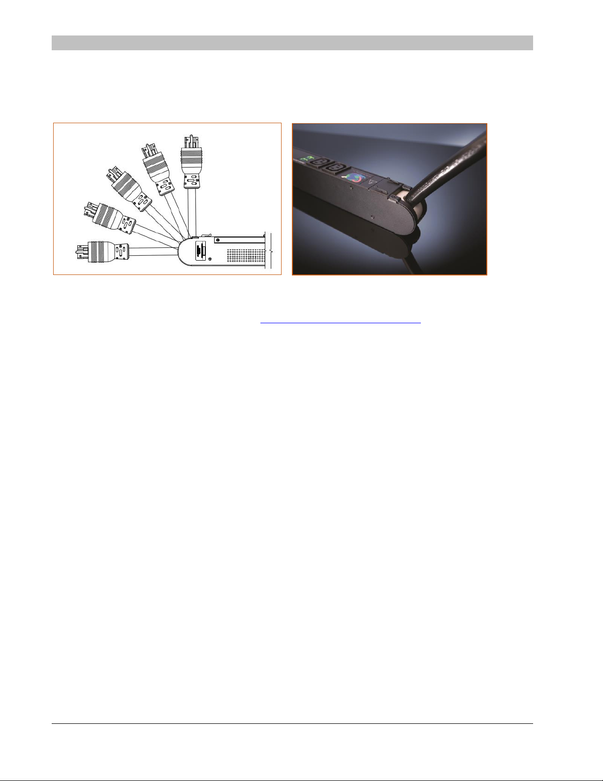
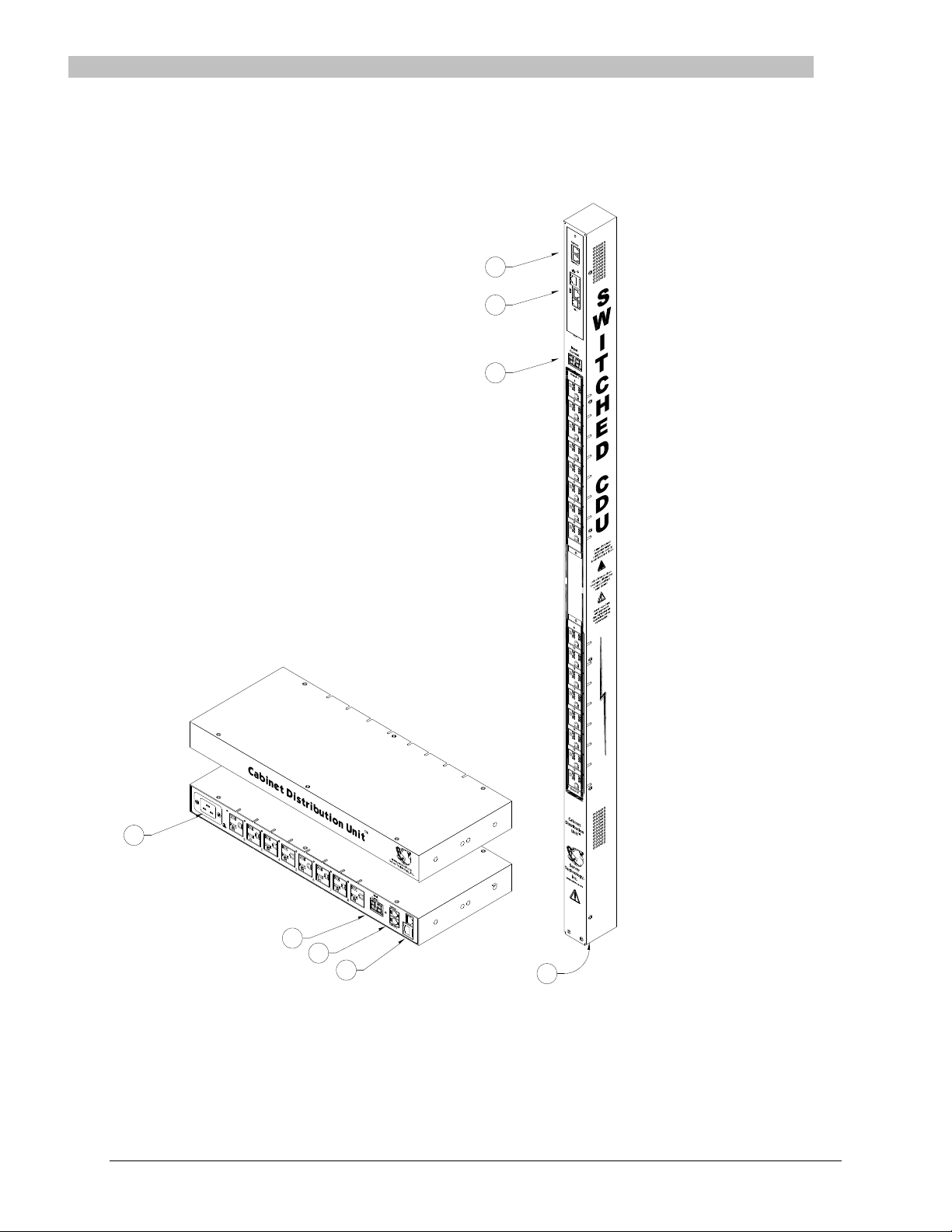
PDU Power Pivot
Server Technology’s PDU Power Pivot flexible infeed provides a simplified power cord routing to the unit with a design that
eliminates bend radius issues.
As illustrated below, the PDU Power Pivot capability can deliver a solution for several types of PDU installations and
mountings, setting the correct cord angle for overhead power, offset overhead power, concrete floor, raised floor, and intra-rack
power.
PDU Power Pivot – Flexible Cord Design
To learn more about PDU Power Pivot and watch a brief video that animates the PDU Power Pivot mounting angles in the
equipment rack, see the Server Technology website at: http://info.servertech.com/PDUpowerpivot
Page 6
6 Introduction Switched PDU
Installation and Operations Manual
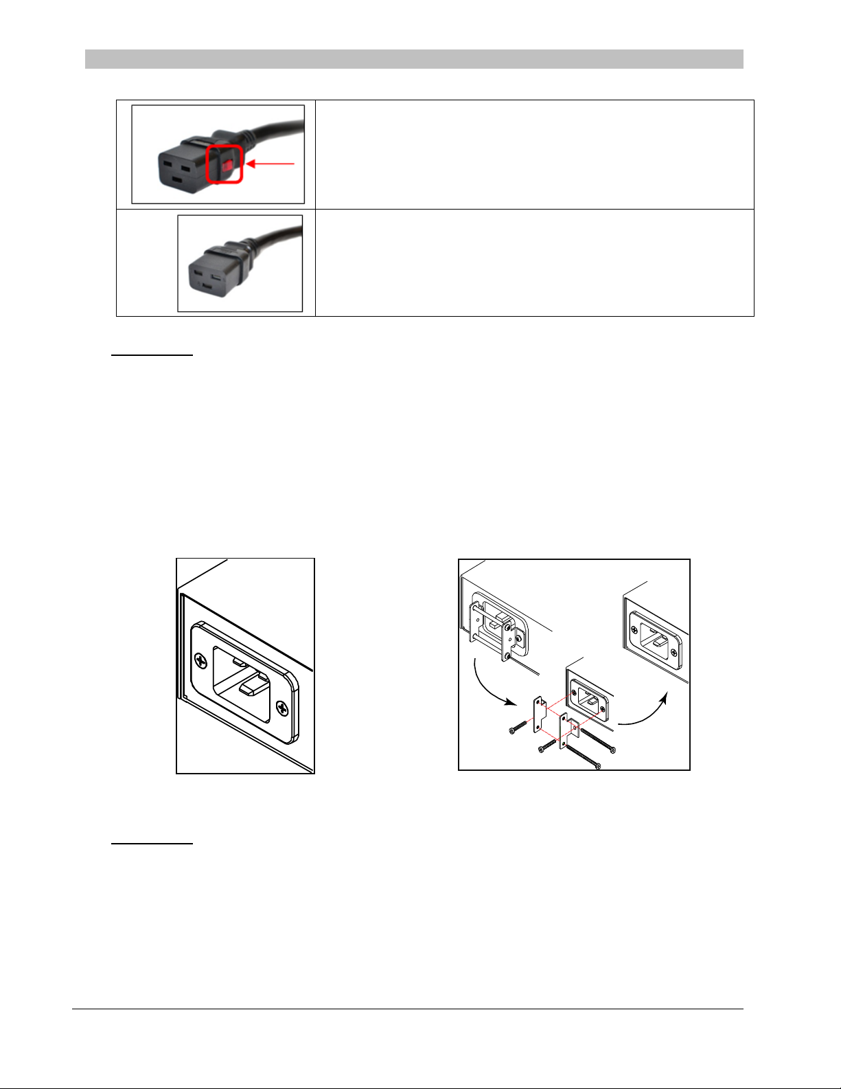
Equipment Overview
1. The power inlet/cord(s) connects the PDU to the electrical power source.
2. The Current LED(s) displays the current load for each infeed, branch or electrical phase per infeed.
3. Two RJ45 connectors for Serial (RS-232) and Ethernet connection.
4. Two mini RJ11 connectors for Temperature/Humidity sensors.
A number is printed above each outlet. These numbers can be used in commands that require an outlet name.
1
2
4
3
4
3
2
1
Switched Rack Power Distribution Unit
Page 7

Switched PDU
Installation and Operations Manual Introduction 7
IPv6 and Server Technology Products
Server Technology is introducing IPv6 “dual stack” support to the PDU product line. IPv6 has been designed to
succeed IPv4 as the dominant communications protocol for internet traffic, to avoid depletions of the IPv4 address
space, and to allow more IP address growth. Many devices already in use support IPv6.
IPv6 has several new operational methods:
Static IPv6 Address: The IPv6 equivalent of Static IPv4.
DHCPv6 Address: The IPv6 equivalent of a DHCP IPv4 address, also known as a “stateful” auto-
configuration of DHCPv6.
IPv6 Stateless Auto-Configured Address – (RFC 4862): An automatically-generated unique link-local IPv6
address used for client based configurations. This address is always present in the Server Technology dual
stack and cannot be disabled.
DHCPv6 Stateless Auto-Configured Address – (RFC 3736): A “stateless” Dynamic Host Configuration
Protocol (DHCP) service for IPv6 (DHCPv6). This address is used by nodes to obtain configuration
information, such as addresses of DNS recursive name servers that do not require the maintenance of any
dynamic state for individual clients.
Firmware – Protocol Support
IPv6 and IPv4 Protocols:
The firmware supports the following network IPv6 and IPv4 protocols:
DNS Ping
FTP (or SFTP) Server SNMPv1/2/3
FTP (or SFTP) Updates SNTP
HTTP or HTTPS
SMTP
Static IPv6 DHCPv6 (stateless and stateful)
Syslog SNMPv1/2/3 Traps
Telnet SSH
IPv4-Only Protocols:
The firmware supports the following network IPv4-only protocols:
Cisco EnergyWise
LDAP
Load Shedding *
RADIUS *
TACACS+
* = may work with IPv6 addresses, but not tested.
Page 8

8 Introduction Switched PDU
Installation and Operations Manual
Network-Enabled Modes
NOTES:
For all network-enabled modes described below, the PDU will set an auto-configured IPv6 address, and if IPv6 router announcements are
active, a stateless DHCP IPv6 address will also be set. Further, in all network-enabled modes, at least one IPv4 or one IPv6 address will
be active.
For maximum backward compatibility, the default network mode is “IPv4 only”.
Network disabled – No IPv4 or IPv6 addresses available.
IPv4 only, DHCP disabled (static IPv4) – If the IPv4 Static Address and Net Mask of the PDU are valid,
they will be set.
IPv4 only, DHCP enabled (DHCP IPv4) – The PDU will try to resolve an IPv4 DHCP address. If a DHCP
address cannot be obtained after 90 seconds, the PDU can: (1) optionally fall back to its static IPv4 settings,
or (2) indefinitely wait to acquire an address based on DHCP configuration settings. This setting is the
default.
Dual IPv6/IPv4, DHCP disabled (static IPv6/IPv4) – If the IPv6 Static Address and prefix of the PDU are
valid, they will be set. Otherwise, the PDU will attempt to use DHCPv6 to obtain an IPv6 address.
In addition, if the IPv4 Static Address and Net Mask of the PDU are valid, they will be set.
Dual IPv6/IPv4, DHCP enabled (DHCP IPv6/IPv4) – The PDU will try to resolve both its IPv6 and IPv4
addresses by DHCP. If both DHCP requests are answered, the primary DNS server of the PDU will become
the primary IPv6 DNS server, and the secondary DNS server of the PDU will become the primary IPv4
DNS server.
If only one of the DHCP requests is answered, the DNS servers of the PDU will map to the primary and
secondary DNS server from that request.
If a DHCP address cannot be obtained after 90 seconds, the PDU can: (1) optionally fall back to its static
IPv4 and/or IPv6 settings, or (2) indefinitely wait to acquire an address based on DHCP configuration
settings.
Page 9

Switched PDU
Installation and Operations Manual Introduction 9
Viewing Network Status
You can obtain the IPv6 network status through the firmware Web Interface or Command Line Interface (CLI). For
the CLI, use the show network command as follows:
Switched CDU: show network
Network Settings
State: DHCP IPv6/IPv4 Network: Dual IPv6/IPv4
Link: Up Negotiation: Auto
Speed: 100 Mbps Duplex: Full
AutoCfg IPv6: FE80::20A:9CFF:FE52:4104/64
IPv6 Address: FD01::1:B51A:E03C/64
IPv4 Address: 10.1.6.230 Subnet Mask: 255.255.0.0
IPv4 Gateway: 10.1.1.1
DNS1: FD01::A01:585
DNS2: 10.1.5.133
Static IPv4/IPv6 Settings
IPv6 Address: FD01::A01:353/64
IPv6 Gateway: ::
IPv4 Address: 10.1.2.253 Subnet Mask: 255.255.0.0
IPv4 Gateway: 10.1.1.1
DNS1: 10.1.5.133
DNS2: 10.1.5.134
DHCP Settings
DHCP: Enabled
FQDN: Enabled [sentry3-524104]
Boot Delay: Enabled
Static Fallback: Enabled
Network Services
Telnet: Enabled Port: 23
SSH: Enabled Port: 22 Auth: Password, Kb-Int
HTTP: Enabled Port: 80
SSL: Enabled Port: 443 Installed Cert: User Encrypted
Access: Optional Stored Files: Cert & Key
User Cert: Enabled User Passphrase: <set>
SNMPv1/2: Enabled Port: 161 TrapPort: 162
SNMPv3: Disabled Port: 161 TrapPort: 162
FTP Server: Enabled Port: 21
SPM Access: Enabled
Command successful
NOTE: The fields IPv4 Address, IPv4 Subnet Mask, IPv4 Gateway, DNS1, and DNS2 are equivalent to existing IPv4 settings except that
current network settings and static settings are displayed separately. This allows you to view both static configuration settings and active
network settings that can be obtained using DHCP. The DNS addresses may be in IPv4 or IPv6 (based on RFC4291) format at this time.
Page 10

10 Installation Switched PDU
Installation and Operations Manual
Chapter 2: Installation
Before installing your Switched Rack Power Distribution Unit, refer to the following lists to make sure you have all
the items shipped with the unit, as well as other items needed for proper installation.
Standard Accessories
Mounting Hardware
Vertical Models:
Button mounting kit with M4 screws.
Horizontal Models:
Two removable L-brackets with four M4 screws.
Expansion Models:
RJ12 to RJ12 crossover cable.
Additional Items for Models with C20 Inlets
Separate power input.
Optional power input retention bracket hardware (can be installed); two removable T-brackets with two 40 mm
screws per input.
Note: This bracket is not compatible with Server Technology Input Power Cords with the self-locking C19
feature. These power cords have the prefix PTCORD-L#.
Optional Accessories
Temperature/humidity sensors (Part Number EMTH-1-1).
Environmental monitor (Part Number EMCU-1-1B).
Vertical mounting brackets; additional mounting options are available in the Accessories section of the
Server Technology website at www.servertech.com.
Additional Required Items
Flathead and Phillips screwdrivers.
Screws, washers, and nuts to attach the PDU to your equipment rack.
Page 11

Switched PDU
Installation and Operations Manual Installation 11
Safety Precautions
This section contains important safety and regulatory information that must be reviewed before installing and using
the Switched Rack Power Distribution Unit.
Only for installation and use in a
Restricted Access Location in
accordance with the following
installation and use instructions.
This equipment should only be
installed by trained personnel.
Destiné à l'installation et l'utilisation dans le
cadre de Restricted Access Location selon
les instructions d'installation et d'utilisation.
Cet équipement est uniquement destiné
à être installé par personnel qualifié.
Nur für Installation und Gebrauch in
eingeschränkten Betriebszonen gemäß der
folgenden Installations-und
Gebrauchsanweisungen.
Dieses Gerät ist nur für den Einbau
durch Personal vorgesehen.
This equipment is designed to be
installed on a dedicated circuit.
The power supply cord shall be a
minimum of 1.5m (4.9ft) and a
maximum of 4.5m (15ft). If using
an extension power cord, the total
length shall also be no more than
the maximum allowed. The plug is
considered the disconnect device
and must be easily accessible.
Cet équipement a été conçu pour être
installé que un circuit dédié. Le cordon
d’alimentation doit être d’au moins 1,5M et
un maximum de 4,5m. Si vous utilisez un
cordon de rallonge, la longueur totale est
également plus que le maximum autorise.
La prise est considérée comme un
dispositif de coupure et doit être facilement
accessible.
Die Geräte sind für eine Installation an
einer fest zugeordneten Leitung ausgelegt.
Die Stromzuleitung hat eine Mindestlänge
von 1,5m, und hochstens 4,5m. Sollten Sie
ein Verlangerrungsnetzkabel, der
Gesamtlange auch nicht mehr als die
maximal zulassige sein. Der Stecker dient
zur Trennung vom Netz und muss einfach
erreichbar sein.
The dedicated circuit must have
circuit breaker or fuse protection.
PDUs have been designed without
a master circuit breaker or fuse to
avoid becoming a single point of
failure. It is the customer’s
responsibility to provide adequate
protection for the dedicated power
circuit. Protection of capacity equal
to the current rating of the PDU
must be provided and must meet
all applicable codes and
regulations. In North America,
protection must have a 10,000A
interrupt capacity.
Le circuit spécialisé doit avoir un disjoncteur
ou une protection de fusible. PDUs ont été
conçus sans disjoncteur général ni fusible
pour éviter que cela devient un seul endroit
de panne. C’est la responsabilité du client
de fournir une protection adéquate pour le
circuit-alimentation spécialisé. Protection de
capacité équivalant à la puissance de
l'équipement, et respectant tous les codes
et normes applicables. Les disjoncteurs ou
fusibles destinés à l'installation en Amérique
du Nord doivent avoir une capacité
d'interruption de 10.000 A.
Der feste Stromkreis muss mit einem
Schutzschalter oder einem
Sicherungsschutz versehen sein. PDUs
verfügt über keinen Hauptschutzschalter
bzw. über keine Sicherung, damit kein
einzelner Fehlerpunkt entstehen kann. Der
Kunde ist dafür verantwortlich, den
Stromkreis sachgemäß zu schützen. Der
Kapazitätsschutz entspricht der aktuellen
Stromstärke der Geräte und muss alle
relevanten Codes und Bestimmungen
erfüllen. Für Installation in Nordamerika
müssen Ausschalter bzw. Sicherung über
10.000 A Unterbrechungskapazität
verfügen.
Models with unterminated power
cords: Input connector must be
installed by qualified service
personnel. Input connector rating
must meet all applicable codes and
regulations.
Modèles avec cordons d'alimentation non
terminées: Le connecteur d’entrée doit être
installé par un personnel qualifié. Entrée
cote de raccordement doit respecter tous
les codes et règlements électriques
applicables.
Modelle mit nicht abgeschlossenen
Netzkabel: Der Eingangsstecker darf nur
von qualifiziertem Wartungspersonal
installiert werden. Eingangsanschluss
Bewertung müssen alle geltenden und
verbindlichen Normen und Vorschriften
entsprechen.
Do not block venting holes when
installing this product. Allow for
maximum airflow at all times.
Ne bloquez pas les orifices d'aération lors
de l'installation de ce produit. Permettre une
circulation d'air maximale à tout moment.
Achten Sie darauf, dass keine
Belüftungslöcher bei der Installation dieses
Produkts. Damit für maximalen Luftstrom
zu allen Zeiten.
Installation Orientation: Vertical
units are designed to be installed
in vertical orientation.
Installation Orientation: Les unités vertical
sont conçues pour être installées dans une
orientation verticale.
Installationsausrichtung: Vertical Einheiten
sind zur vertikalen Installation vorgesehen.
Always disconnect the power
supply cord before servicing to
avoid electrical shock. For
products with two input power
cords, both must be disconnected
before servicing.
Toujours débrancher le cordon
d'alimentation avant de l'ouverture pour
éviter un choc électrique. Pour les produits
avec deux cordons d'alimentation d'entrée,
les deux doivent être déconnectés avant
l'entretien.
Trennen Sie das Netzkabel, bevor Sie
Wartungsarbeiten Öffnung einen
elektrischen Schlag zu vermeiden. Für
Produkte mit zwei Eingangsstromkabel,
sowohl, müssen vor der Wartung
abgeschaltet werden.
WARNING! High leakage current!
Earth connection is essential
before connecting supply!
ATTENTION! Haut fuite très possible! Une
connection de masse est essentielle avant
de connecter l’alimentation !
ACHTUNG! Hoher Ableitstrom! Ein
Erdungsanschluss ist vor dem Einschalten
der Stromzufuhr erforderlich!
WARNING! Cx-xxE-x units double
pole/neutral fusing
ATTENTION! Les unités Cx-xxE-x Double
Pôle/Fusible sur le Neutre
ACHTUNG!: Cx-xxE-x Zweipolige bzw.
Neutralleiter-Sicherung
ATTENTION! Observe precautions
for handling Electrostatic Sensitive
Devices.
Attention ! Respecter les mesures de
sécurité en manipulant des dispositifs
sensibles aux décharges électrostatiques.
Achtung! Vorsichtshinweise zur
Handhabung elektrostatisch empfindlicher
Geräte beachten.
Products rated for 240/415VAC
may be fitted with a plug that is
rated for a higher voltage. Caution
must be taken to assure that the
rating of the unit and the supply
voltage match.
Les produits prévus pour 240/415VAC peut
être équipé d'un bouchon qui est conçu
pour une tension plus élevée. Des
précautions doivent être prises pour assurer
que la cote de l’unité et la tension
d’alimentation correspond.
Produkte die für 240/415VAC zugelassen
sind können mit einem Stecker der für eine
höhere Spannung ausgestattet sein.
Vorsicht ist geboten, um sicherzustellen,
dass die erlaubten Betriebswerte des
Gerätes und der Versorgungsspannung
zueinander passen.
Page 12

12 Installation Switched PDU
Installation and Operations Manual
NEBS GR-1089-Core Information
For NEBS certified products only.
These products are intended to be installed in Network Communications Facilities and in locations where the NEC applies.
This product is suitable for installation in a Common Bonding Network (CBN).
WARNING: The intra-building port(s) of the equipment or subassembly is suitable for connection to intra-building or
unexposed wiring or cabling only. The intra-building port(s) of the equipment or subassembly MUST NOT be metallically
connected to interfaces that connect to the OSP or its wiring.
These interfaces are designed for use as intra-building interfaces only (Type 2 or Type 4 ports as described in
GR-1089-CORE, Issue 5) and require isolation from the exposed OSP cabling. The addition of Primary Protectors is not
sufficient protection in order to connect these interfaces metallically to OSP wiring.
Page 13
Switched PDU
Installation and Operations Manual Installation 13
Input Power Cord Retention Options for PDUs with IEC C20 Inlets
Determine which Detachable Input Cord was supplied with the unit:
For the following Detachable Input Cords with the self-locking
IEC C19 feature, follow Procedure A below.
PTCORD-L1, PTCORD-L2, PTCORD-L3, PTCORD-L5, PTCORD-L6, or
PTCORD-L7.
For the following Detachable Input Cords, follow Procedure B below.
PTCORD-1, PTCORD-2, PTCORD-3, PTCORD-4, PTCORD-5, PTCORD-6,
or PTCORD-7.
Procedure A
If the unit was supplied with a Detachable Input Power Cord with a self-locking IEC C19, install it directly into the
C20 inlet.
1. Verify the Retention Bracket Assembly (part number KIT-0016) is not installed.
a. If KIT-0016 is installed, remove the two screws attaching the bracket to the IEC 60320 C20 inlet
to the enclosure.
b. Remove the Retention Bracket Assembly.
c. Re-attach the two screws to the IEC C20 and securely tighten.
2. Push the C19 from the Detachable Input Cord firmly into the C20 inlet to ensure it is properly seated.
C20 Inlet without Retention Bracket Assembly KIT-0016, Retention Bracket Assembly
Procedure B
If the unit was supplied with a Detachable Input Power Cord without the self-locking C19 feature, install with the
Retention Bracket Assembly (part number KIT-0016), followed by the power cord.
1. Remove the two screws attaching the IEC 60320 C20 inlet to the enclosure.
2. Assemble and attach the Retention Bracket to the enclosure as shown
3. Connect the power cord. Ensure the C19 is fully seated against the C20 inlet. (It may be necessary to loosen
some of the Retention Bracket Assembly screws to allow the C19 plug to be properly installed.)
4. Tighten the Retention Bracket Assembly to restrain the power cord.
Page 14
14 Installation Switched PDU
Installation and Operations Manual
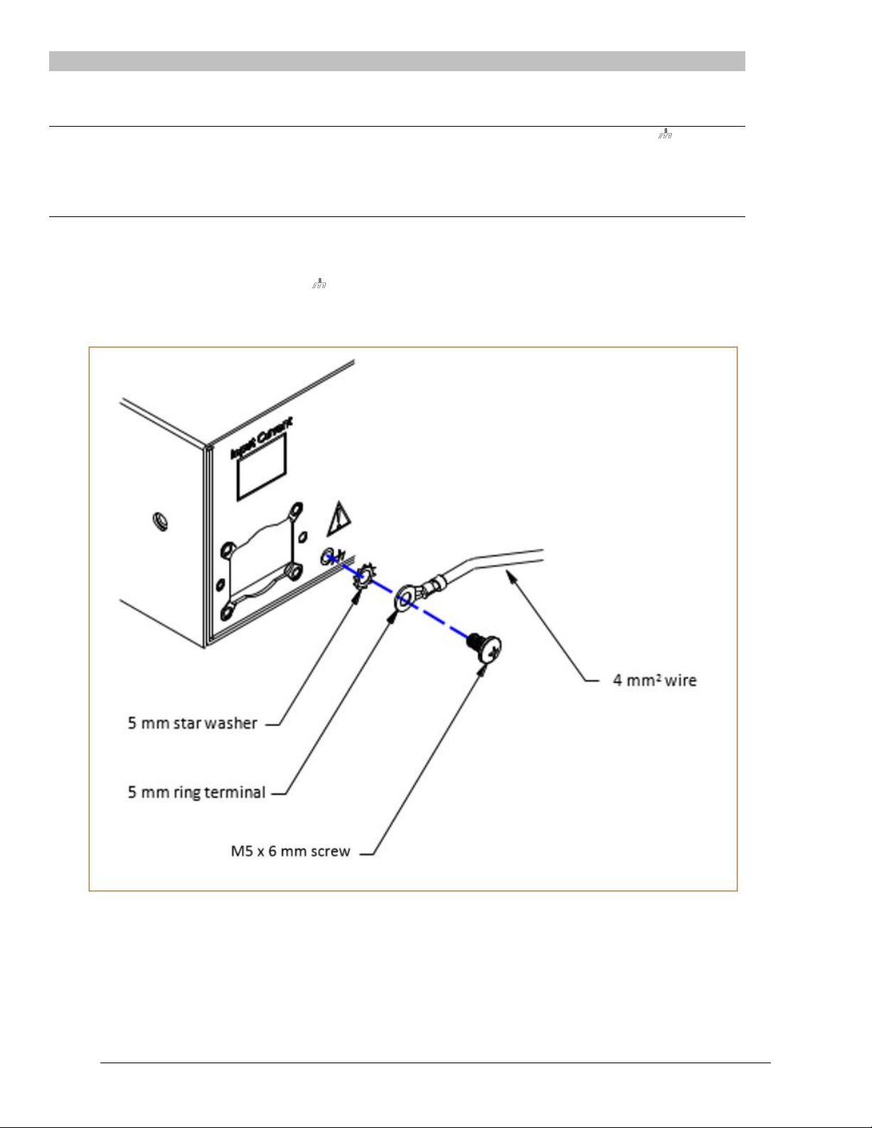
Attaching Safety Earth Ground Connection
Server Technology PDUs are supplied with an external safety ground connection to provide an alternate ground path for fault
currents, and to maintain the same ground reference between it and the equipment rack.
NOTE: The auxiliary external ground location may vary. Most PDUs will have it located near the power cord entry located near the symbol.
User-supplied materials:
One 5 mm internal (or external) tooth star washer;
One 4.0 mm
2
(10 AWG) wire with 5 mm ring terminal;
One metric M5 x 6 mm coarse pitch screw.
Instructions:
1. Connect one end of the ground wire to the equipment cabinet or local ground.
2. Locate the PDU external ground near the symbol.
3. Connect the other end with a ring terminal and a M5 screw to the PDU external ground. To ensure proper grounding
to the chassis, use a star washer between the ring terminal and the PDU.
Page 15
Switched PDU
Installation and Operations Manual Installation 15
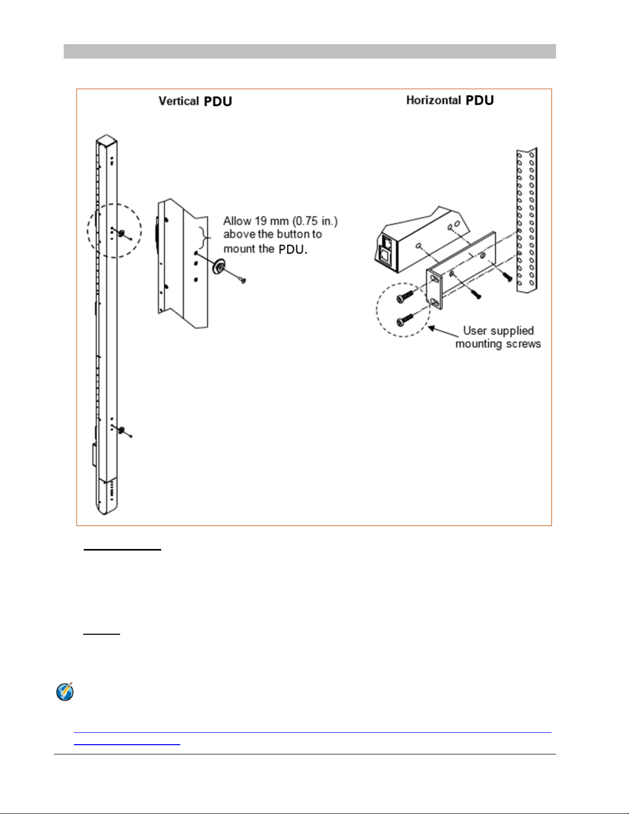
Mounting the PDU
The following illustration shows how to mount the Switched PDU in vertical or horizontal orientation:
Horizontal/Rack
1. Select the appropriate bracket mounting points for proper mounting depth within the rack.
2. Attach the L-brackets to these mounting points with two screws for each bracket.
3. Install the enclosure into your rack, using the slots in each bracket. The slots allow about 6 mm (0.25 inch) of
horizontal adaptability to align with the mounting holes of your rack.
Vertical
The Switched PDU is supplied with button mounting kit(s). Distribute the buttons vertically and attach to the PDU as
appropriate for the cabinet. An additional 19 mm (0.75 inch) of clearance is required at the top of the PDU to allow the
button to mount into the keyholes.
Note: For more information about horizontal/vertical mounting options for the Switched PDU, see the
Server Technology PDU Mounting Bracket Catalog:
http://cdn1.servertech.com/assets/documents/documents/1803/original/Mounting_Bracket_Catalog.201412-30.pdf?1420823515
Page 16

16 Installation Switched PDU
Installation and Operations Manual
Attaching the Expansion Module
Connect the expansion module unit with the provided RJ12 crossover cable at the Link port on the Switched PDU.
NOTE: The overall length of the RJ12 crossover cable should not exceed 10 feet.
Connecting to the Power Source
On 30A units, the input power cord is attached to the base of the unit. On units with a total maximum output <30A,
you must first attach the power cord to the unit before connecting the unit to the power source.
To attach a power cord to the unit:
1. Plug the female end of the power cord firmly into its connector at the base.
2. Use a screwdriver to tighten the two screws on the retention bracket.
To connect to the power source:
Plug the male end of the power cord into the AC power source.
Connecting Devices
To avoid the possibility of noise due to arcing:
1. Keep the device’s on/off switch in the off position until after it is plugged into the outlet.
2. Connect devices to the PDU outlets.
NOTE: Server Technology recommends even distribution of attached devices across all available outlets to avoid exceeding the outlet,
branch or phase limitations.
Always disconnect ALL power supply cords before opening to avoid electrical shock.
Afin d’éviter les chocs électriques, débranchez TOUTES les cables électrique avant d’ouvrir.
Vor dem Offnen immer Netzleitung abziehen um elektrischen Schlag zu vermeiden.
Connecting the Sensors
The Switched PDU is equipped with two mini RJ11 T/H ports for attachment of the Temperature/Humidity sensors.
Attach the mini RJ11 plug of the sensor(s) to the appropriate T/H port.
Connecting to the Unit
Serial (RS232) Port
The Switched Cabinet Distribution Unit is equipped with an RJ45 Serial RS-232 port for attachment to a PC or
networked terminal server using the supplied RJ45 to RJ45 crossover cable and RJ45 to DB9F serial port adapter as
required. For more information about the Serial RS-232 port, see the “Data Connections” section in Appendix C:
Technical Specifications.
Page 17

Switched PDU
Installation and Operations Manual Installation 17
Ethernet Port
The Switched Cabinet Distribution Unit is equipped with an RJ45 10/100Base-T Ethernet port for attachment to an
existing network. This connection allows access to the Switched PDU via Telnet or Web.
The Switched PDU is configured with the following network defaults to allow unit configuration out-of-the-box
through either Telnet or Web:
NOTE: When installed on a DHCP enabled networks, the following network defaults do not apply because the PDU ships with DHCP
support enabled.
IP address: 192.168.1.254
Subnet Mask: 255.255.255.0
Gateway: 192.168.1.1
The local PC network connection must be configured as noted below:
NOTE: For instructions about reconfiguring the network connection, contact your system administrator. A restart may be required for the
reconfiguration of your network to take effect.
IP address: 192.168.1.x (where x is 2-253)
Subnet Mask: 255.255.255.0
Page 18

Page 19

Chapter 3: Operations
INTERFACES 21
Outlet Naming and Grouping 21
Models with a Single Power Infeed ...................................................................................... 21
Models with Multiple Power Infeeds .................................................................................... 21
Usernames and Passwords 21
WEB INTERFACE 22
Logging In 22
System Summary 23
Outlet Control 26
Individual ............................................................................................................................. 26
Group ................................................................................................................................... 26
Power Monitoring 27
Input Feeds........................................................................................................................... 27
System .................................................................................................................................. 27
UPS ...................................................................................................................................... 27
Environmental Monitoring 28
Sensors ................................................................................................................................. 28
Shutdown 28
Outlets .................................................................................................................................. 28
Configuration 28
System .................................................................................................................................. 28
Network ................................................................................................................................ 31
Telnet/SSH............................................................................................................................ 33
HTTP/SSL ............................................................................................................................ 34
Serial Ports .......................................................................................................................... 35
Towers .................................................................................................................................. 37
Input Feeds........................................................................................................................... 38
UPS ...................................................................................................................................... 38
Outlets .................................................................................................................................. 39
Groups ................................................................................................................................. 39
Users .................................................................................................................................... 40
FTP ...................................................................................................................................... 42
SNTP/Syslog ......................................................................................................................... 43
SNMP/Thresholds ................................................................................................................ 44
LDAP ................................................................................................................................... 46
TACACS+ ............................................................................................................................ 48
RADIUS ............................................................................................................................... 50
SMTP/Email ......................................................................................................................... 51
Features ............................................................................................................................... 52
Tools 52
Ping ...................................................................................................................................... 52
Change Password ................................................................................................................ 52
Firmware.............................................................................................................................. 52
View Log .............................................................................................................................. 52
Restart .................................................................................................................................. 52
COMMAND LINE INTERFACE 53
Logging In 53
Operations Commands 56
Administration Commands 61
User Administration ................................................................................................ ............. 61
Outlet Administration ........................................................................................................... 65
Input Feed Administration ................................................................................................... 67
Tower Administration .......................................................................................................... 68
Group Administration .......................................................................................................... 70
Environmental Monitor Administration ............................................................................... 72
Serial Port Administration ................................................................................................... 72
System Administration .......................................................................................................... 75
TCP/IP Administration ........................................................................................................ 83
HTTP Administration ........................................................................................................... 86
Page 20

20 Operations Switched PDU
Installation and Operations Manual
Sentry Power Manager (SPM) Administration .................................................................... 86
Telnet Administration ........................................................................................................... 87
FTP Administration .............................................................................................................. 87
SNTP Administration ........................................................................................................... 89
UPS Administration ............................................................................................................. 91
Feature Administration ........................................................................................................ 95
Page 21

Switched PDU
Installation and Operations Manual Operations 21
Interfaces
The Switched Cabinet Distribution Unit has two interfaces: the Web interface accessed via the HTTP enabled
Ethernet connections, and the command line for serial and Telnet connections.
Outlet Naming and Grouping
Models with a Single Power Infeed
Absolute names are specified by a period (.) followed by a tower letter and outlet number. The tower letter for the
Switched Cabinet Distribution Unit is A and the tower letter for the optional Expansion Module is B.
Models with Multiple Power Infeeds
For units with multiple infeed connectors, absolute names are specified by a period (.) followed by the tower letter,
the infeed letter and outlet number.
Example: The absolute name for outlet 8 on the B infeed of tower A is .AB8.
Outlets can also be included in one or more named groups of outlets, enabling you to issue a command that affects all
outlets in a named group.
Usernames and Passwords
The Switched Cabinet Distribution Unit has one predefined administrative user account (username/password:
admn/admn), and supports a maximum of 112 defined user accounts.
NOTE: For security, Server Technology recommends removal of the predefined administrative user account after a new account with
administrative rights has been created.
Only an administrative-level user can perform operations such as creating/removing user accounts and command
privileges, changing passwords and displaying user information. An administrator can also view the status of all sensors
and power inputs.
Usernames can contain from 1-16 characters and are not case sensitive; spaces are not allowed. Passwords can
contain up to 16 characters, and are case sensitive.
Page 22
22 Operations Switched PDU
Installation and Operations Manual
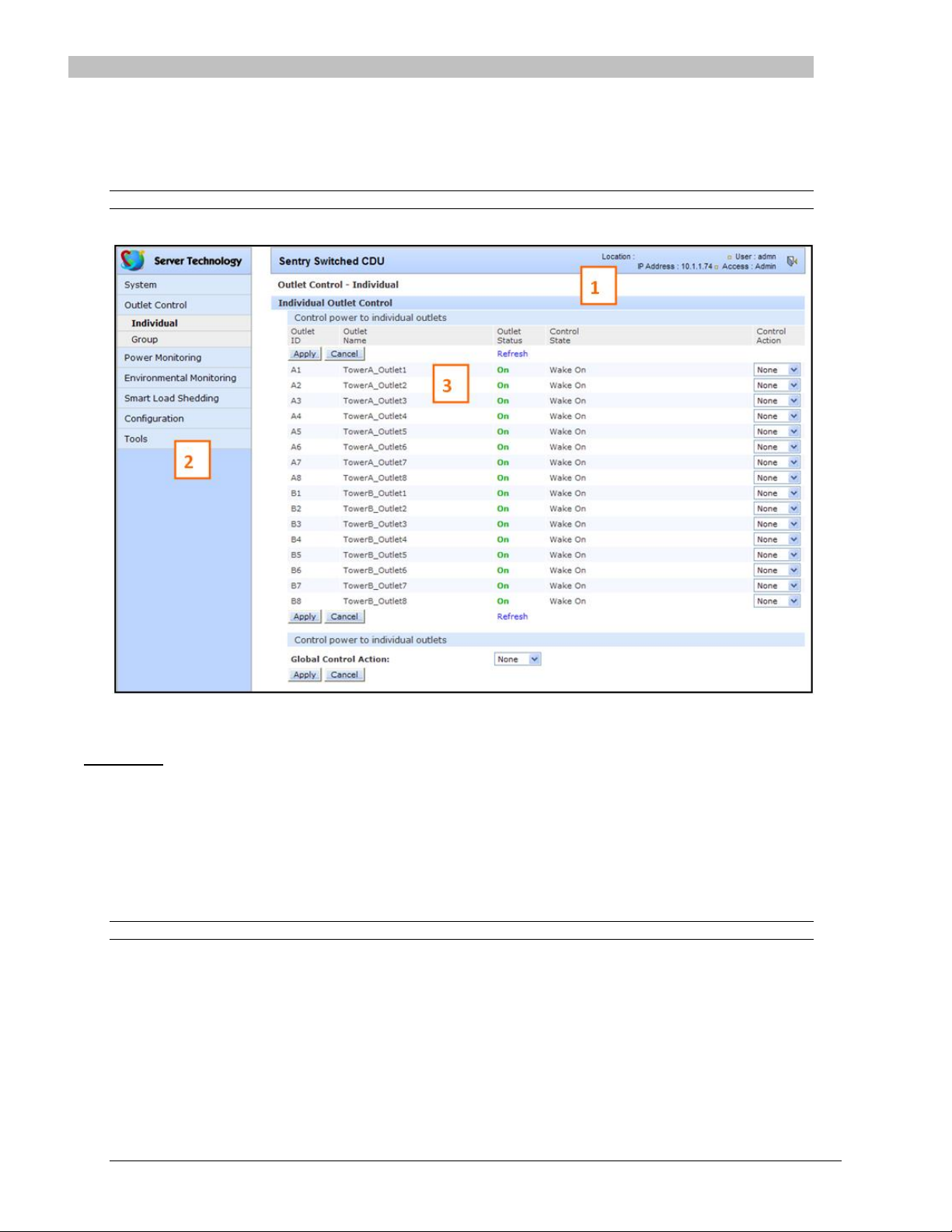
Web Interface
The Web Interface provides web-based access to the firmware. The interface is designed with three major sections,
illustrated below.
1. System Header: Shows PDU description and location, IP address, and user/access.
2. Navigation Bar: Provides access to PDU configuration, control action, or status page.
3. Details Window: Current control/status information based on the page selected from the navigation bar.
NOTE: The blinking of the PDU location string (IP address) in the System Header section may not work with all web browsers.
This example shows the Outlet Control > Individual page:
Example of Firmware Web Interface for the Switched PDU
Logging In
Logging in through the Web interface requires directing the Web client to the configured IP address of the unit.
To log in by Web interface:
In the login window, enter a valid username and password and click OK.
If you enter an invalid username or password, you will be prompted again.
You are given three attempts to enter a valid username and password combination. If all three fail, the session ends
and a protected page will be displayed.
NOTE: The default username/password is admn/admn.
Page 23

Switched PDU
Installation and Operations Manual Operations 23
System Summary
The System Summary is typically displayed as the default page at user login to the firmware Web Interface. If you do
not have environmental monitor access for a PDU, your default page at login will be the Outlet Control page (shown
in Figure 3 above).
Both the System Summary page and the Outlet Control page display automatically at login and do not require
enabling.
The System Summary page contains general system, line, humidity, and temperature status information. The colorcoded sensor graphs shown in the example below provide a quick and efficient real-time view for monitoring
environmental conditions in your PDU network.
Example of System Summary Page
The System Summary page displays precise current and system power consumption in your PDU network. Dynamic
updates (without a full page refresh) allow you to assess critical system statistics with close to instantaneous
feedback. This performance is useful for monitoring new installation or power distribution changes in high-density
computing environments. Power system administrators can also quickly identify thermal and humidity concerns that
might otherwise escalate into costly infrastructure repairs if left unchecked.
As long as the System Summary page is active, the sensor graphs are continually updating system statistics and
threshold values. The data with the most impact on the system is displayed to reduce your analysis and
troubleshooting time. You can quickly analyze and correct a PDU if a sudden operating condition affects your device
network.
NOTE: Because the System Summary page continually requests updated status information from the PDU, the page does not time-out. You
will need to navigate to another page or manually log off.
System Information
Uptime: Displays the cumulative time the PDU has been up and running since the last unit restarted. Uptime shows
continuous, real-time system updates with an approximate 5-second automatic refresh. A manual refresh of the
System Summary page is not required.
Firmware Version: Shows the current firmware version.
Ethernet NIC S/N: Displays the PDU serial number derived from the Ethernet NIC.
Page 24

24 Operations Switched PDU
Installation and Operations Manual
Active Users: Displays the number of active user sessions accessing the firmware. These sessions include serial,
TELNET, SSH, and Web sessions. Active Users also shows sessions that an unauthorized user may be attempting to
access. The number shown in Active Users changes instantly as the number of active user sessions change. A total of
4 concurrent web user sessions are allowed (HTTP or HTTPS).
NOTE: Depending on your web browser, multiple web accesses from the same machine are often treated as one user.
Total Power Consumption: Displays the total system power (in Watts) being distributed by the current PDU
configuration.
Line Status
The Line Status graph displays a blinking warning (yellow), whenever the total input load on an infeed exceeds the
present user set threshold. If an overload occurs, a blinking error condition (red) is displayed. The unit continues to
display these yellow and red states until the condition changes or the problem has been resolved.
The default input feed high load threshold is 80% of the input feed maximum load capacity.
NOTE: The input feed high threshold is user-defined. You must configure this threshold value on the SNMP/Thresholds page or the
Command Line Interface (CLI).
Temperature Status
The Temperature Status graph displays a blinking error whenever temperature exceeds the low or high threshold. The
PDU will continue to display this state until the condition changes or the problem has been resolved.
For the temperature sensor, the default range of low/high temperature values is 5º-45º C (41º-115º F).
Up to four sets of dual temperature/humidity sensors can be displayed in this graph for a total of eight possible
temperature sensor graphs. A thin blue line separates each set based on the tower or environmental monitor.
NOTE: The temperature threshold values are user-defined. You must configure these threshold values on the SNMP/Thresholds page or the
Command Line Interface (CLI).
Humidity Status
The Humidity Status graph displays a blinking error whenever humidity exceeds the low or high threshold. The PDU
will continue to display this state until the condition changes or the problem has been resolved.
For the humidity sensor, the default range of low/high humidity percentage is 0-100% (relative humidity).
Up to four sets of dual temperature/humidity sensors can be displayed in this graph for a total of eight possible
humidity sensor graphs. A thin blue line separates each set based on the tower or environmental monitor.
NOTE: The humidity threshold values are user-defined. You must configure these threshold values on the SNMP/Thresholds page or the
Command Line Interface (CLI).
Field Descriptions
The following fields and icons are viewed left to right for Line Status, Temperature Status, and Humidity Status:
Icon: Provides quick viewing of current operational state: Information , Warning and Critical .
ID: Device input feed or sensor identifier.
Name: Descriptive, user-defined name for each input infeed or sensor.
Load, Temp, Humidity: Current state of the reported input load (in amps), current temperature, or current
percentage of relative humidity.
Low Limit: Displays the user-defined low limit of the load, temperature, or humidity graph. These values depend on
the sensor limited and cannot be set by the user. For example, a 0ºC low limit would be displayed as for a
temperature sensor graph in Celsius.
Sensor Graph and Level Indicator: The horizontal sensor graph shows current operating conditions in color-coded
segments. See the section below, “Sensor Graph Color Coding” for details. The level indicator appears across the
graph to indicate the relative position of the current data value with respect to the minimum (low limit) and maximum
(high limit) values displayed at the left and right of the graph.
Page 25
Switched PDU
Installation and Operations Manual Operations 25
High Limit: Displays the high limit of the load, temperature, or humidity graph. These values depend on the sensor
limits are cannot be set by the user. For example, a 100ºC high limit would be displayed as for a temperature
sensor graph in Celsius.
Status: One of several operating conditions:
System Summary – Status Descriptions
Icon Status Description
Reading Unit is reading a new or restored sensor.
Normal Indicates normal operation.
Load High Infeed current load exceeds present High threshold.
Over Load Infeed current load exceeds the measurable range for the infeed.
Temp Low Current temperature falls below present Low threshold.
Temp High Current temperature exceeds present High threshold.
Humid Low Current percentage of relative humidity falls below present Low threshold.
Humid High Current percentage of relative humidity exceeds present High threshold.
Lost The connection was lost to a sensor that was previously detected and the sensor is pulled from the
original environment monitoring statistics. There is no data to report, the graph is meaningless, and
the threshold settings remain displayed but are grayed.
Sensor Graph Color-Coding
The following colors change dynamically on the sensor graphs to communicate operating conditions:
Line (Load) Status:
Green = Normal
Yellow = High load (load configured by user)
Red = Overload (based on device characteristics)
User configures load capacity at Configuration > SNMP/Thresholds > Input Feed Traps and Thresholds
Temperature Status:
Blue = cold; low temperature (threshold configured by user)
Green = acceptable temperature range
Red = hot; high temperature (threshold configured by user)
User configures low/high temperature thresholds at Configuration > SNMP/Thresholds > Sensor Traps and
Thresholds
Humidity Status:
Blue = wet; high humidity (threshold configured by user)
Green = acceptable percentage of relative humidity
Yellow = dry; low humidity (threshold configured by user)
User configures low/high relative humidity thresholds at Configuration > SNMP/Thresholds > Sensor Traps and
Thresholds
Page 26

26 Operations Switched PDU
Installation and Operations Manual
Logical Group Separators
Logical groups are separated by a thin blue line on the System Summary page as shown in the following example
between Tower A_InfeedA and Tower B_InfeedA:
This grouping includes master/link units in addition to some branched units.
Up to three blue line dividers can be displayed on the System Summary page between all sensor groups.
Outlet Control
The Outlet Control section offers access to the Individual and Group outlet control pages. From the Individual and
Group pages, the user can review and manipulate power control functions for all outlets and groups assigned to the
current user. Both pages include the outlet’s absolute and descriptive names, the Outlet Status reported to the PDU by
the outlet, the current Control State being applied by the PDU, and the outlet load in amperes.
Available outlet and group power states can be set to on, off, or reboot.
Individual
The Individual outlet control page displays all outlets assigned to the current user. The user can apply on, off, or
reboot actions to individual, multiple, or all accessible outlets.
To apply actions to individual or multiple outlets:
In the Individual Outlet Control section, select the desired action from the Control Action drop-down menu for each
individual outlet to be changed, and click Apply.
To apply an action to all outlets:
In the Global Control section, select the desired action from the Control Action drop-down menu and click Apply.
Group
The Group outlet control page displays all groups assigned to the current user, as well as the outlets for each group.
To select a group:
Select the group name from the drop-down menu and click Select. The page will refresh to display all outlets
associated to the selected group name.
To apply an action to a group:
Select the desired action from the drop-down menu and click Apply.
Page 27

Switched PDU
Installation and Operations Manual Operations 27
Outlet State/Control State Field Values
Outlet State Control State Description
On On Outlet is on
Off Off Outlet is off
Off Pend On Outlet is off and about to turn on in response to a sequence timer
Off Reboot Outlet is off and a Reboot action has been initiated
On Idle On A restart has occurred – Last Control State has been maintained
Off Idle Off A restart has occurred – Last Control State has been maintained
On Wake On A power-loss has occurred – Wakeup State has been applied
Off Wake Off A power-loss has occurred – Wakeup State has been applied
On/Wait Off Outlet state in transition – Re-query of outlet status required
Off/Wait On Outlet state in transition – Re-query of outlet status required
On/Error varies Error State – Outlet should be off, but current is sensed at the outlet
Off/Error varies Error State – Outlet should be on, but no current is sensed at the outlet
Off/Fuse On Outlet should be on, but a blown fuse has been detected
On/Fuse On Outlet should be on, but a blown fuse has been detected downstream
No Comm varies Communication to the outlet has been lost. Control state will be applied when communication
is re-established.
Power Monitoring
Input Feeds
The Input Feeds page displays:
The absolute and descriptive names of the infeed
Infeed status
Input/branch phase load in amperes
Input Voltage
Calculated power usage in Watts.
Monitor pages (like the Input Feeds page) refresh occasionally to reflect current PDU status.
System
The System page displays:
Calculated power usage for all infeeds in watts
Configured total system area in square feet
Calculated power usage in watts/square feet
Tower monitoring – tower ID, tower name, and tower status
NOTE: For 3-phase systems, if the Out-of-Balance Alerting feature is enabled, and the system goes into a load out-of-balance condition,
the Tower Status field will display the alert “3ph Out-of-Balance”, unless there is a higher priority tower error state to report.
Monitor pages (like the System page) refresh occasionally to reflect current PDU status.
UPS
The UPS page displays the following information for each UPS device associated with the unit:
Status
Voltage
Hostname/IP address
NOTE: The UPS page displays both IPv4 and IPv6 formats in the Hostname/IP field.
Monitor pages (like the UPS page) refresh occasionally to reflect current PDU status.
Page 28

28 Operations Switched PDU
Installation and Operations Manual
Environmental Monitoring
Sensors
The Sensors page displays:
Absolute and descriptive names of the temperature/humidity sensor
Temperature/humidity sensor readings and percentage of relative humidity
Monitor pages (like the Sensors page) refresh occasionally to reflect current PDU status.
Temperature/Humidity Sensor Status
Status Description
Found The PDU found the sensor and connection is established.
Not Found On a fresh reboot, the PDU does not find a sensor.
Lost The connection to a previously found sensor is now lost.
No Comm Communication loss occurred due to a hardware issue (not loss of communication with the probes).1
1
= The ENV part of the sensor supports two Temperature/Humidity (T/H) probes as part of the master unit, two T/H
probes as part of the link unit, and the optional EMCU-1-1 (which can support two T/H probes, four contact-closure
monitoring points, and one water sensor). The “No Comm” sensor status is not loss of communication with probes
themselves.
Shutdown
The Shutdown section offers access to all Remote Shutdown configuration options. This section is available to
administrative level users only. For more information and the configuration requirements, see the “Remote
Shutdown” section.
Outlets
Enabling or disabling Remote Shutdown support:
Select or deselect outlets to enable/disable Remote Shutdown support for in the Shutdown/Delay field and click
Apply.
Setting the Remote Shutdown delay:
Enter the shutdown delay (in seconds) in the outlet Shutdown/Delay field and click Apply. Valid range is 1-900
seconds.
Editing the target server’s Hostname/IP address:
In the outlet Hostname/IP field, enter an IP address or Hostname and click Apply.
Enabling or disabling shutdown script support:
Select or deselect outlet to enable/disable shutdown script support for in the Script/Delay column and click Apply.
Setting the shutdown script delay:
Enter the shutdown delay (in minutes) in the outlet Script/Delay field and click Apply.
Configuration
The Configuration section offers access to all unit configuration options. This section is available to administrative
level users only.
System
The System configuration page is used for reference of system information such as Ethernet NIC Serial Number,
Ethernet MAC address and system firmware and hardware revisions as well as assignment and maintenance of other
system wide configurations.
For descriptive names, up to 24 alphanumeric and other typed characters (ASCII 33-126 decimal) are allowed; spaces
are not allowed.
NOTE: Spaces can be used for the location description only.
Page 29
Switched PDU
Installation and Operations Manual Operations 29
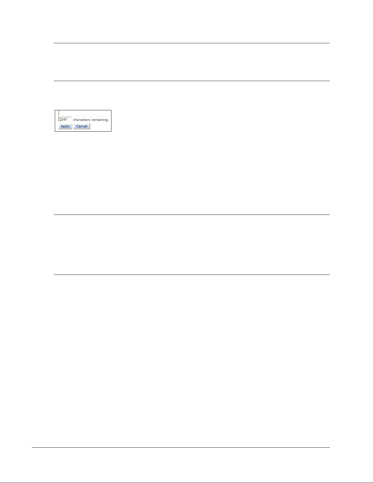
Creating a pre-login banner:
Click the Login Banner link. On the subsequent Login Banner page, type pre-login banner text and click Apply.
NOTES:
The pre-login banner can be up to 2069 characters in length and is displayed prior to the login prompt. If left blank, a system banner will
not be displayed prior to the login prompt.
For an SSH connection, the banner length is truncated to 1500 bytes in SSH packets to avoid failure of the SSH connection when
configured with a long login banner.
The Login Banner displays the following Characters Remaining box to show you in real-time as you type how many of
the 2069 maximum characters are still available for you to complete your banner. The box adjusts dynamically as you
type or delete characters.
If you reach the maximum 2069 characters, the box displays “-1”. To clear your entry and start over, click Cancel.
Creating a descriptive system location name:
Enter a descriptive name and click Apply.
Configuring the Input Current LED display orientation:
Select Normal or Inverted from the drop-down menu and click Apply.
Configuring the LED display orientation:
From the Display Orientation drop-down list, select Normal or Inverted, and click Apply.
NOTES:
Only specific PDU models are equipped with an accelerometer chip that senses device orientation. If equipped, your PDU automatically
aligns the LED display orientation (depending on its current direction), and the option “Auto” displays in the Display Orientation
drop-down list by default. In addition, the actual mounting of the unit, such as “<Normal> or <Inverted>”, appears to the right of
the "Auto" option. However, even if your model does have the sensor for device orientation, you can still select the Normal or
Inverted option from the list to override the capability of the hardware.
If your model does not have the accelerometer chip, you will need to configure the LED display orientation by selecting Normal or
Inverted.
Setting the outlet sequence order:
The PDU lets you configure the power-on sequence of outlets.
The Normal option powers-on outlets in ascending numeric order by outlet number, for example, from outlet 1-8. The
Reversed option powers on outlets in descending order by outlet number; for example, from outlet 8-1.
The Reversed option is useful when the PDU is mounted with inverted orientation and the last outlet (in this example,
outlet 8) is in the first position.
From the Outlet Sequence Order drop-down menu, select Normal or Reversed, and click Apply.
Page 30

30 Operations Switched PDU
Installation and Operations Manual
Enabling or disabling strong password requirements:
The Switched PDU supports enforcement of strong passwords for enhanced security. When enabled, all new
passwords must be a minimum of 8 characters in length with at least one uppercase letter, one lowercase letter, one
number and one special character.
Acceptable strong passwords:
n0tOnmyw@tch
john2STI?
H3reUgo!
NOTE: Strong password requirements also enforce a minimum change of four character positions when defining new strong passwords.
Select Enabled or Disabled from the Strong Passwords drop-down menu and click Apply.
NOTE: The strong password requirement is applied against all new passwords.
Enabling or disabling the configuration reset button:
Select Enabled or Disabled from the Configuration Reset Button drop-down menu and click Apply.
Setting the temperature scale:
Select Celsius or Fahrenheit from the Temperature Scale drop-down menu and click Apply.
Setting the system area (footprint):
Enter a system area value in the Area (Footprint) field and click Apply.
Setting the system area unit of measure:
Select Square Feet or Square Meters from the Area (Footprint) drop-down menu and click Apply.
Setting the power factor:
The Power Factor value calculates the power usage displayed in the Power Monitoring pages.
Type a numeric value in the Power Factor field (from 0.50 to 1.00) and click Apply.
Setting the 3-phase load out-of-balance threshold:
The threshold (percentage) specified determines when the current on the lines of a 3-phase system are out-of-balance
between the three phases of power. If the alerting feature is enabled, an alert will be sent when an out-of-balance condition
occurs.
In the 3-Phase Load Out-of-Balance Threshold field, type a value from 0 to 100%, and click Apply.
Setting the 3-phase load out-of-balance alerting:
This setting enables/disables the sending of an alert when the current on the lines of a 3-phase system are past a pre-set
threshold (percentage) and are out-of-balance between the three phases of power.
From the 3-Phase Load Out-of-Balance Alerting drop-down menu, select Enabled or Disabled, and click Apply.
NOTES:
When a device with 3-phase input voltage is out-of-balance, efficiency is reduced and the unit is prevented from reaching maximum
capacity. When an alert for the out-of-balance condition is received (if the alerting feature is enabled), it may be necessary to adjust
distribution of the loads.
For 3-phase systems, if the Out-of-Balance Alerting feature is enabled, and the system goes into a load out-of-balance condition, the
Tower Status field on the “Power Monitoring – System” web page will display the alert “3ph Out-of-Balance”, unless there is a higher
priority tower error state to report.
Configuring the Command Line Interface (CLI) session timeout:
Enter a timeout period (in minutes) in the CLI Session Timeout field, and click Apply.
The valid timeout range is 1 to 1440 minutes (24 hours); the default is 5 minutes.
Page 31

Switched PDU
Installation and Operations Manual Operations 31
Configuring the web session (Web Interface) timeout:
Enter a timeout period (in minutes) in the Web Session Timeout field.
The valid timeout range is 1 to 1440 minutes (24 hours); the default is 5 minutes.
Enabling/Disabling StartUp Stick :
StartUp Stick is a Server Technology tool for mass configuration of PDU operating parameters.
Select Enabled or Disabled from the StartUp Stick drop-down menu and click Apply.
Creating a descriptive unit name:
Click on the Tower Names link.
On the subsequent Tower Names page, enter a descriptive name and click Apply.
Creating a descriptive input feed name:
Click on the Input Feed Names link.
On the subsequent Input Feed Names page, enter a descriptive name and click Apply.
Creating a descriptive outlet name:
Click on the Outlet Names link which will open the Outlets configuration page. For more information about creating
descriptive outlet names, see the “Outlets” section.
Creating a descriptive serial port name:
Click on the Serial Port Names link which will open the Serial Ports configuration page.
Creating a descriptive environmental monitor name:
Click on the Environmental Monitor Names link.
On the subsequent Environmental Monitor Names page, enter a descriptive name and click Apply.
Creating descriptive sensor names:
Click on the Sensor Names link.
On the subsequent Sensor Names page, enter a descriptive name and click Apply.
Network
The Network configuration page allows the administrator to maintain the network interface by determining IPv6 and
IPv4 status, network state, IP address, gateway, subnet mask, primary/secondary DNS addresses, and the necessary
settings and options for DHCP.
NOTE: For maximum backward compatibility, the default network mode is “IPv4 only”.
Page 32

32 Operations Switched PDU
Installation and Operations Manual
Network:
The Network drop-down menu determines the acquisition method used for the protocol stack, IPv4 address, and IPv6
address. From the Network drop-down menu, select the acquisition method for your network (Disabled, IPv4 only, or
Dual IPv6/IPv4), and click Apply.
State:
The view-only State field shows the current IPv6/IPv4 network status and can display any of the following values:
Current Network States
Acquiring
Disabled
Disconnected
DHCP IPv4
DHCP IPv6
DHCP IPv6/IPv4 (both available)
IPv4 Failed (Static IPv4 problem)
IPv6 Failed (Static IPv6 problem)
Static IPv4
Static IPv6
Static IPv6/IPv4 (both available)
Unknown
Additional network communication values are displayed for viewing only: Link, Speed, Duplex, and Negotiation. Also
displayed for viewing are the IPv6 and IPv4 IP address, subnet mask, gateway, and primary/secondary DNS addresses.
Setting the IPv6 or IPv4 static IP address, gateway, subnet mask, or DSN address:
In the appropriate fields, type the IP address, gateway, subnet mask, or DNS address, and click Apply.
NOTE: IPv6 address formats are accepted in the IPv6 Address field and IPv6 Gateway field. IPv4 formats are accepted in the IPv4-named
Address, Subnet Mask, and Gateway fields.
Enabling Dynamic Host Configuration Protocol (DHCP):
To enable DHCP, check the Enable checkbox. To disable DHCP, uncheck (clear) the checkbox.
Click Apply.
Setting the Fully-Qualified Domain Name (FQDN):
To enable the FQDN, check the Enable checkbox and accept the default name “sentry3-521384” (or type a different
name). To disable the FQDN, uncheck the checkbox.
Click Apply.
Enabling the DHCP boot delay:
To enable the boot delay, check the Enable checkbox. To disable the boot delay, uncheck (clear) the checkbox.
Click Apply.
Enabling the Boot Delay option gives the PDU approximately 100-seconds to establish a connection through a
DHCP server. This interval allows various network component activities to occur as the PDU powers up (such
as obtaining SNTP time stamps for logging). This is the default state.
Disabling the Boot Delay option forces the PDU to boot after approximately 5-seconds regardless of the
DHCP acquisition state. This speeds up a boot when a DHCP server is connected to one of the outlets in the
PDU. In this configuration, SNMP traps, SNTP, and other protocols will not be available until a DHCP
address has been resolved.
NOTES:
The Boot Delay option executes only when DHCP is enabled.
The firmware can detect network link integrity and will wait for network connection. This means that if the network is not currently
connected, the enabled Boot Delay option will be ignored.
Page 33

Switched PDU
Installation and Operations Manual Operations 33
Enabling static address fallback:
NOTE: The Static Address Fallback option executes only when DHCP is enabled.
To enable static address fallback, check the Enable checkbox. To disable, uncheck (clear) the checkbox.
Click Apply.
Enabling the Static Address Fallback option informs the PDU to automatically fall back to a static address if
a DHCP server does not respond after 100-seconds. This is the default state.
Disabling the Static Address Fallback option generates DHCP server requests until the PDU obtains a
dynamic address.
NOTE: If the DHCP server boot time is excessive, you may need to disable the DHCP Static Address Fallback option.
Network defaults
The Switched PDU is configured with the following network defaults to allow unit configuration out-of-the-box
through either Telnet or Web:
IP address: 192.168.1.254
Subnet Mask: 255.255.255.0
Gateway: 192.168.1.1
The initial local PC network connection must be configured as noted below:
NOTE: For instructions about reconfiguring the network connection, contact your system administrator. A restart may be required for the
reconfiguration of your network to take effect.
IP address: 192.168.1.x (where x is 2-253)
Subnet Mask: 255.255.255.0
NOTE: The unit must be restarted after network configuration changes.
Setting the IP address, subnet mask, gateway, or DNS address:
In the appropriate field, enter the IP address, subnet mask, gateway address or DNS address and click Apply.
Telnet/SSH
The Telnet/SSH configuration page enables or disables Telnet and SSH support and configures the port number that
the Telnet or SSH server watches.
Enabling or disabling Telnet or SSH support:
Select Enabled or Disabled from the appropriate Server drop-down menu and click Apply.
Changing the Telnet or SSH server port number:
In the appropriate Port field, enter the port number and click Apply.
Enabling or disabling SSH server authentication methods:
The SSH server supports the Password and the Keyboard-Interactive authentication methods for security.
Password is an authentication method in which the SSH client gathers username/password credentials and makes the
authentication request to the SSH sever with the credentials. The Password method is controlled by the SSH client.
Keyboard-Interactive is an authentication method in which the SSH server controls an information field followed by one
or more prompts requesting credential information from the SSH client. The client gathers credential information keyed-in
by the user and sends it back to the server. The Keyboard-Interactive method is controlled by the SSH server.
Individual enabling and disabling of the Password and Keyboard-Interactive authentication methods are supported to
allow an SSH client to be forced to use a specific method. Although both methods are available, by enabling the
Keyboard-Interactive method and disabling the Password method, the SSH client is forced to used Keyboard-Interactive,
which is required to display the login banner.
NOTE: At least one authentication method must be enabled.
Select the Password checkbox and/or the Keyboard-Interactive checkbox and click Apply.
Page 34

34 Operations Switched PDU
Installation and Operations Manual
HTTP/SSL
The HTTP/SSL page configures HTTP server options, SSL options (including user-defined certificates), and
determines settings for the Sentry Power Manager (SPM) enterprise software product.
Enabling or disabling HTTP or SSL support:
From the HTTP or SSL Server drop-down menu, select Enabled or Disabled, and click Apply.
NOTE: SSL-encrypted (HTTPS) must be used for secure website connections.
Setting SSL secure access:
SSL allows either optional or required connections. The default secure access is optional.
Optional: Both non-secure (HTTP) and SSL-encrypted connections (HTTPS) are allowed access.
Required: Only SSL-encrypted connections (HTTPS) are allowed access.
From the Secure Access drop-down menu, select Optional or Required, and click Apply.
Changing the HTTP server or SSL port number:
In the HTTP or SSL section of the page, in the Port field, type the port number, and click Apply. The HTTP default
port number is 80; the SSL default port number is 443.
Uploading a custom user certificate:
Enabling and disabling user certificates:
In the User Certificate drop-down menu, select Enabled. Provide a passphrase (0-47 characters) for the new
certificate. To change the passphrase, type a new passphrase and check the Change checkbox.
Click Apply.
The Stored Files section displays a message to confirm the upload status of the user certificate and its related public
key.
Custom User Certificate Messages
Message Description and Valid Values/Range
Cert & Key Both the user certificate and its key were uploaded successfully.
Cert User certificate was uploaded without a key.
No Cert User certificate was not uploaded.
Factory Encrypted User certificate was encrypted and uploaded at product assembly.
None Neither the user certificate nor its key were uploaded.
Uploading the certificate:
NOTE: You can enable user certificates and provide a passphrase using either the firmware Web interface or the Command Line Interface
(CLI). However, the uploading of a custom user certificate can only be done using the Web interface – there are no equivalent commands
for uploading user certificates.
To upload a user certificate, click the Upload link. The Upload window displays. Type the certificate filename (or
key filename) and click the Upload button. The upload status is displayed in the Stored Files section as described
above.
Removing a Certificate:
To remove a user certificate, click the Remove link. A message displays to confirm the removal of the certificate.
Page 35

Switched PDU
Installation and Operations Manual Operations 35
Setting the Sentry Power Manager (SPM) options:
The Sentry Power Manager (SPM) is Server Technology’s enterprise management software product for the data
center. The configuration options provided allow you to enable/disable SPM and reset the SPM password to its
default.
NOTE: The SPM options apply only if you are currently using Server Technology’s SPM software.
SPM Secure Access:
If your operation does not currently use SPM software, you can disable SPM Secure Access. However, if disabled,
the PDU will not be able to use the SPM suite of secure network capabilities or the advanced remote configuration.
Select Enabled or Disabled from the SPM Secure Access drop-down menu and click Apply.
NOTE: Both HTTP and SSL must be enabled or the SPM Secure Access option will not be permitted. When SPM Secure Access is
permitted, the default is Enabled.
SPM Password:
Each PDU has a default unique SPM password that is used to communicate between SPM and the PDU. When SPM
discovers a PDU in the network, SPM changes this password into a different unique password for added security. The
SPM then continues to manage or alter these passwords as required for system security.
If a PDU is relocated or swapped from the system after a password was generated, SPM may not be able to reestablish a connection to the unit. The Set SPM Reset Password command allows you to reset to the internal default
password of the PDU so SPM can re-discover the device and add it to the system. Once the unit has been acquired by
SPM, no further action is necessary.
To reset the password, check SPM Password and click Apply.
NOTE: Do not reset the password if SPM communication has already been established.
Serial Ports
The Serial Ports configuration page allows maintenance to the serial port.
NOTE: Pass-Thru connections can only be initiated from the command line interface via a Telnet/SSH session.
Setting the data-rate for all serial ports:
Select the serial port data-rate from the drop-down menu and click Apply.
Setting the serial port timeout value:
The Serial Port Timeout Value sets the serial port inactivity timeout period for individual ports. The timeout period
defines the maximum period of inactivity before automatically closing the Pass-Thru session.
The valid range for the timeout is 0 to 60 (in minutes). The default timeout is 5 minutes. Setting the timeout value to
“0” disables the timeout.
Click the Edit link in the Action column next to the individual port to be configured.
Type the timeout minutes in the Connection Timeout field and click Apply.
Creating a descriptive serial port name:
Click the Edit link in the Action column next to the port to be configured.
On the following Serial Ports Edit page, enter a descriptive name up to 24 alphanumeric and other typed characters - (ASCII 33
to 126 decimal) are allowed; spaces are not allowed. Press Apply.
Enabling or disabling serial port active signal checking:
Click on the Edit link in the Action column next to the port to be configured.
On the following Serial Ports Edit page, select On or Off from the DSR Check drop-down menu and click Apply.
Page 36

36 Operations Switched PDU
Installation and Operations Manual
Enabling or disabling the Command Line Interface (CLI):
This option enables or disables availability of the CLI for issuing action commands to the PDU. If disabled, only the
firmware Web user interface will be available.
Click on the Edit link in the Action column next to the port to be configured.
On the following Serial Ports Edit page, select Enabled or Disabled from the CLI drop-down menu and click Apply.
Enabling or disabling the Serial Command Protocol (SCP):
This option allows SCP functions to be enabled or disabled for a specific serial port.
Click on the Edit link in the Action column next to the port to be configured.
On the following Serial Ports Edit page, select Enabled or Disabled from the SCP drop-down menu and click Apply.
NOTES:
Upon a coldboot of the system, if the Coldboot Alert feature is enabled, the system will send a ½ second RS-232 break out to any
SCP-enabled serial ports.
The SCP option must be enabled to use the Bluetooth Android solution.
Enabling or disabling the Serial Command Protocol (SCP) emulation:
This option notifies SCP of an MRV device on a specific serial port.
Click on the Edit link in the Action column next to the port to be configured.
On the following Serial Ports Edit page, select None or MRV from the SCP Emulation drop-down menu and click
Apply.
Enabling or disabling the RFTAG option:
This option makes RF Code sensor tags available for the Server Technology wireless monitoring solution.
Click on the Edit link in the Action column next to the port to be configured.
On the following Serial Ports Edit page, select Enabled or Disabled from the RFTAG drop-down menu and click
Apply.
Page 37

Switched PDU
Installation and Operations Manual Operations 37
Configuring the Bluetooth™ options:
If the PDU has been equipped for the mobile monitoring solution using Bluetooth ® technology, several Bluetooth
parameters will be available for editing on the Serial Ports configuration page.
Click the Edit link in the Action column next to the AUX port to configure the following parameters.
Provide a value as described for each parameter field, and click Apply.
Firmware Bluetooth Parameters
Parameter Description and Valid Values/Range
Bluetooth Name Descriptive name of the Bluetooth module that displays in the list of discovered modules
on the Android device. The default module name is “ST Eye”. The name cannot be blank;
Valid range is 1-31 characters.
Bluetooth Discoverability Settings that determine the current status of the pushbutton on the Bluetooth module.
Always – The Bluetooth module is discoverable, even without pressing the pushbutton.
Limited – (Default). The pushbutton on the Bluetooth module must be pressed to make
the module discoverable for 60-seconds.
Never – The Bluetooth module is never in discoverable mode.
Bluetooth Pin Code The pin code is available for legacy Bluetooth modules that require a pin to pair the module.
Although not used in current Bluetooth modules, the pin code is supported if needed.
Default is 9611; must be 4-digits; range is 0000 to 9999.
Bluetooth Transmission Power Designated transmission power (dbm) for the Bluetooth module. Note that lowering the
transmission power reduces the effective range of the module. Default is 0;
range is -6 to 4 dbm.
Towers
The Towers configuration page is used for assignment and/or editing of:
Descriptive names
Serial and Model numbers
Operation voltage types
NOTE: If set at the factory, you cannot edit the serial number, model number, or voltage type.
Creating a descriptive tower name:
In the Tower Name field, enter a descriptive name and click Apply.
Setting the tower serial number:
In the Serial Number field, enter the serial number of the unit and click Apply.
Setting the tower model number:
In the Model Number field, enter the model number of the unit and click Apply.
Setting the operational AC or DC voltage type:
From the AC/DC drop-down menu, select AC or DC, and click Apply.
Setting the operational AC voltage type:
From the 3-Phase drop-down menu, select yes or no, and click Apply.
Page 38

38 Operations Switched PDU
Installation and Operations Manual
Input Feeds
The Input Feeds configuration page allows you to assign and edit input feed descriptive names, operational voltage,
and maximum load capacity.
Creating a descriptive input feed name:
In the Input Feed Name field, enter a descriptive name and click Apply.
Setting the infeed operational voltage:
In the Input Feed Voltage field, enter a value from 1 to 480 and click Apply.
NOTE: If Smart Load-Shedding has been activated and UPS voltage polling configured for an infeed, the polled voltage value will be used
for all power calculations.
Setting the infeed maximum load capacity:
In the Input Feed Load Capacity field, enter a value from 1 to 255 and click Apply.
UPS
The UPS Configuration page allows adding a new UPS device and configuring the UPS devices connected to the
Switched PDU.
NOTE: The UPS page accepts both IPv4 and IPv6 formats in the Hostname/IP field.
To add a new UPS:
Select the UPS manufacturer type from the Type drop-down list, type an IP address (or hostname) for the UPS, and click
Apply.
To edit the UPS type:
Under the Action heading, click the Edit link for the UPS to be configured. The Configuration UPS page reformats to
an edit page where UPS device settings are configured and UPS devices are associated with an infeed.
Selecting the UPS type:
Select the UPS manufacturer type from the UPS Type drop-down list and click Apply.
Editing the UPS Hostname/IP Address:
In the Hostname/IP field, type an IP Address or Hostname and click Apply.
Editing the UPS SNMP GET community string:
In the SNMP GET Community String field, type the community string configured on the UPS device and click
Apply.
Enabling/Disabling UPS voltage polling:
From the Poll UPS Voltage drop-down list, select Enabled or Disabled and click Apply.
Editing the UPS SNMP port number:
In the Port field, type the port number and click Apply.
Associate the UPS with an infeed:
Select the infeed(s) powered by the UPS and click Apply.
To remove a UPS:
On the Configuration UPS page, under the Action heading, click the Remove link for the UPS you want to remove.
Page 39

Switched PDU
Installation and Operations Manual Operations 39
Outlets
The Outlets configuration page configures options for all outlets and outlet shutdown settings.
Setting the outlet reboot delay:
Provide the reboot interval (in seconds) in the Reboot Delay field and click Apply.
Editing the outlet descriptive name:
Click the Edit link in the Action column next to the outlet to be configured.
On the subsequent Outlets edit page, type a descriptive name. Up to 24 alphanumeric and other typed characters
(ASCII 33 to 126 decimal) are allowed; spaces are not allowed. Click Apply.
Changing the outlet wakeup state:
Click the Edit link in the Action column next to the outlet to be configured.
On the subsequent Outlet edit page, select On, Off or Last from the Wakeup State drop-down menu, and click
Apply.
Setting the outlet post-on delay:
Click the Edit link in the Action column next to the outlet to be configured.
On the following Outlet edit page, type the post-on delay (in seconds) in the Post-On Delay field, and click Apply.
Setting the outlet locked (no control) state:
The Outlet Locked feature protects against accidental switching off of critical equipment that should rarely, if ever, be
relay-controlled. The feature also prevents unused outlets from being turned on, for example, when a circuit is at
capacity and additional devices/loads should not be turned on.
Click the Edit link in the Action column next to the outlet to be configured.
On the subsequent Outlet edit page, check the Locked (No Control) checkbox to lock the outlet (or uncheck the box to
unlock the outlet), and click Apply.
NOTE: Outlets can only be locked and unlocked individually by outlet name; there is no global outlet lock/unlock command action.
When an outlet is configured into the locked state, the outlet will lock at its current control state (On or Off). The
outlet control state will then change to Locked On or Locked Off.
The locked control state (Yes or No) displays in the outlets list on the Outlets configuration page:
Control actions for a locked outlet will not be available in the web interface, and the outlet will not be affected by
group actions or Smart Load Shedding actions. SNMP and CLI control actions will be ignored for a locked outlet.
Groups
The Groups configuration page allows you to create and delete groups and to assign outlets to groups.
Creating a group:
Enter a descriptive group name in the Group Name field. Up to 24 alphanumeric and other typed characters (ASCII
33 to 126 decimal) are allowed; spaces are not allowed. Press Apply.
Removing a group:
Click on the Remove link in the Action column for the group to be removed and click Yes on the subsequent
confirmation window.
Adding and Deleting outlets from a group:
Press the Edit link in the Action column for the associated group.
On the subsequent Group Edit page, select or deselect outlets to be included in that group. Press Apply.
Page 40

40 Operations Switched PDU
Installation and Operations Manual
Users
The Users configuration page is used for creation and removal of usernames, assignment of accessible outlets and
group, assignment of privilege levels, and the changing of user passwords.
Creating a new user:
Enter a user name in the Username field. Up to 16 alphanumeric and other typed characters (ASCII 33 to 126
decimal) are allowed; spaces are not allowed.
Enter a password for the new user and verify in the Password and Verify Password fields. For security, password
characters are not displayed. Press Apply.
Removing a user:
Click on the Remove link in the Action column for the user to be removed and click Yes on the subsequent
confirmation window.
Changing a user password:
Click on the Edit link in the Action column for the associated user.
On the subsequent User Edit page, enter a password and verify the new password for the new user in the Password and
Verify Password fields. For security, password characters are not displayed. Press Apply.
Changing a user’s access privilege level:
The Switched PDU has the following defined privilege levels:
Admin: Full-access for all configuration, control (On, Off, Reboot), status and
serial/Pass-Thru ports.
Power User: Full-access for all control (On, Off, Reboot), status and
serial/Pass-Thru ports.
User: Partial-access for control (On, Off, Reboot), status and Pass-Thru of assigned outlets, groups
and serial/Pass-Thru ports.
Reboot-Only: Partial-access for control (Reboot), status and Pass-Thru of assigned outlets, groups and
serial/Pass-Thru ports.
On-Only: Partial-access for control (On), status and Pass-Thru of assigned outlets, groups and
serial/Pass-Thru ports.
View-Only: Partial-access for status and Pass-Thru of assigned outlets, groups and serial/Pass-Thru ports.
The administrator can also grant administrative privileges to other user accounts allowing the unit to have more than one
administrative-level user.
NOTE: You cannot remove administrative privileges from the default admn user unless you have already granted administrative access to
another user account.
Click on the Edit link in the Action column for the associated user.
On the subsequent User Edit page, select Admin, Power-User, User, Reboot-only, On-only
or View-only from the Access Level drop-down menu and click Apply.
Granting or removing environmental monitoring access:
Click on the Edit link in the Action column for the associated user.
On the subsequent User Edit page, select Yes or No from the Environmental Monitoring drop-down menu and click
Apply.
NOTE: Granting access to environmental monitoring (temperature/humidity/sensors) to a non-admin user also grants that user access to
power monitoring (outlets, infeeds, towers – all the environmental data of the PDU).
Page 41

Switched PDU
Installation and Operations Manual Operations 41
Adding and deleting outlet access:
Click on the Outlets link in the Access column for the associated user.
On the subsequent User Outlets page, select or deselect outlets to be accessed by the user and click Apply.
Adding and deleting group access:
Click on the Groups link in the Access column for the associated user.
On the subsequent User Groups page, select or deselect group to be accessed by the user and click Apply.
Adding and deleting serial port access:
Click on the Ports link in the Access column for the associated user.
On the subsequent User Ports page, select or deselect ports to be accessed by the user and click Apply.
Page 42

42 Operations Switched PDU
Installation and Operations Manual
FTP
The FTP configuration page allows you to set up and maintain all settings required to perform an FTP firmware
upload, configure automatic FTP updates, or system configuration uploads/downloads. For more information about
uploading firmware, see Appendix B.
NOTES:
The FTP page accepts both IPv4 and IPv6 formats in the Host field.
Secure File Transport Protocol (SFTP) is also supported for encrypted SSH transport over the network.
Setting the FTP Host Address:
Enter the IP address or hostname in the Host field and click Apply.
Setting the FTP username:
Enter the FTP server username in the Username field, and click Apply.
Setting the FTP password:
Enter the FTP server password in the Password field, and click Apply.
Setting the filepath:
Enter the path of the file to be uploaded in the Directory field, and click Apply.
Setting the filename for upload:
Enter the filename of the file to be uploaded in the Filename field, and click Apply.
Testing the FTP upload configuration:
This test validates that the unit is able to contact and log onto the specified FTP server, download the firmware file,
and verify that the firmware file is valid for the unit. Click Test.
Enabling or disabling automatic updates:
The Switched PDU has the capability to schedule automatic firmware updates. When enabled and configured, the unit
regularly checks the FTP server for a new firmware image and uploads it.
Select Enabled or Disabled from the drop-down menu and click Apply.
Setting the automatic update scheduled day:
Select the desired day for the automatic update from the drop-down menu and click Apply.
Setting the automatic update scheduled hour:
Select the desired hour for the automatic update from the drop-down menu and click Apply.
Page 43

Switched PDU
Installation and Operations Manual Operations 43
Enabling or disabling the FTP server:
The Switched PDU has the ability to upload and download system configuration files to ease implementation across
multiple PDUs.
Select Enabled or Disabled from the drop-down menu and click Apply.
NOTE: The FTP server must be enabled for configuration upload or download.
SNTP/Syslog
The SNTP/Syslog page sets the options for the SNTP server, time zone, Daylight Saving Time (DST) automatic clock
adjustment, and Syslog server.
About Daylight Saving Time (DST)
Support for DST is disabled by default. When enabled, the date and time are automatically adjusted forward one hour
between the starting and ending dates and times (which can be configured).
NOTE: If Daylight Saving Time (DST) is enabled, all system time displays will be shown with the current DST start/end date/time settings.
The default time zone is set for the United Stated until at least 2015.
The time zone format is: mo.w.d/h:m:s, as follows:
mo = month from January to December (1-12)
w = week number (1-4) or the last week (5)
d = day of week from Sunday to Saturday (0-6)
h = hour (0-23)
m = minute (0-59)
s = second (0-59)
Setting the local date/time:
The Date/Time (Local) field shows the current DST settings. To increment the settings – based on updates to the
start/end day/time options – click Update.
Setting the SNTP primary/secondary server address:
The Primary/Secondary Host fields contact the SNTP server. The fields are populated with the external NTP pool
time zones “2.servertech.pool.ntp.org” and “1.servertech.pool.ntp.org”. These are the default names for new PDUs
that have not yet been time-set.
Enter the IP address or hostname in the Primary Host and/or Secondary Host field and click Apply.
Setting the Local GMT offset (hours/minutes):
The GMT offset supports all standard international time zones from -12:59 to +14.59. The GMT offset can be set in
minutes to accommodate partial-hour time zones.
Select the local offset from GMT value from the drop-down menu and click Apply.
Enabling or disabling Daylight Saving Time (DST):
Select Enabled or Disabled from the drop-down menu and click Apply.
Setting Daylight Saving Time (DST) start/end date/time options:
Select the week/day/month and hour/minute/second for the start date/time and end date/time from the drop-down
menus and click Apply.
Setting the Syslog server address:
Enter the IP address or hostname in the Primary and/or Secondary Host field and click Apply.
NOTE: Both IPv4 and IPv6 formats are accepted in the Primary/Secondary Host fields.
Changing the Syslog server port number:
In the Syslog Port field, enter the port number and click Apply.
Page 44

44 Operations Switched PDU
Installation and Operations Manual
SNMP/Thresholds
The SNMP/Thresholds configuration page allows setup and maintenance of all SNMP agent settings required to
enable SNMP. The page also provides access to the trap configuration pages for towers, input feed, environmental
monitor, and sensors.
NOTE: Traps are generated according to a hierarchical architecture; for example, if a tower status enters a trap condition, only the tower
status trap is generated. Infeed and outlet status traps are suppressed until the tower status returns to normal.
About SNMP versions:
The firmware supports SNMP versions 1, 2, and 3.
SNMP version 3 supports authentication and encryption on a per user basis. Authentication types are None and MD5.
Encryption types are None and DES. If you use authentication, you must use encryption.
Two SNMPv3 users are supported: one user with read-write (RW) access, and one user with read-only (RO) access
Both users have the same configuration parameters, and you can configure each user independently.
SNMPv2 and SNMPv3 can be enabled or disabled independently. You can have SNMPv2 and/or SNMPv3, or none.
Enabling or disabling SNMP v3 support:
Select Enabled or Disabled from the SNMPv3 Agent drop-down menu and click Apply.
NOTE: The default for SNMP support is Enabled. When Server Technology products are shipped, the default SNMP configuration for the
GET community string is set to “public” and the SET community string is left blank.
Setting the SNMPv3 read-write (RW) user or read-only (RO) user:
Enter the Read-Write User or Read-Only User username and click Apply. A valid username can be set to any value
between 1-31 characters.
Configuring the SNMPv3 read-write (RW) user or read-only (RO) user authentication type:
From the Read-Write User or Read-Only User Authentication Type drop-down menu, select None or MD5, and click
Apply. To clear the password, check Change Password.
Setting the SNMPv3 read-write (RW) user or read-only (RO) user authentication password:
Enter the Read-Write (RW) User or Read-Only (RO) User Password and, and click Apply. To clear the password,
check Change Password. A valid authentication password can be set to any value between 1-39 characters. A blank
password will clear the string.
Configuring the SNMPv3 read-write (RW) user or read-only (RO) user privacy type:
From the Read-Write User or Read-Only User Privacy Type drop-down menu, select None or DES, and click Apply.
To clear the password, check Change Password.
Setting the SNMPv3 read-write (RW) user or read-only (RO) user privacy password:
Enter the Read-Write User or Read-Only User privacy password and, and click Apply. To clear the password, check
Change Password. A valid password can be set to any value between 1-31 characters
Setting the SNMPv3 trap username:
The optional trap username displays on SNMP activity logs to identify user actions.
Type a name in the Trap Username field and click Apply. The trap username can be 1-31 alphanumeric characters;
spaces are allowed; and the name is case sensitive.
Page 45

Switched PDU
Installation and Operations Manual Operations 45
Configuring general parameters for any SNMP version:
Setting trap destinations:
Type an IP address or hostname as necessary in the trap destination field(s) and click Apply.
NOTE: Both IPv4 and IPv6 formats are accepted in the “Trap Destination 1” and “Trap Destination 2” fields.
Setting the error trap repeat time:
Type a time value in the Error Trap Repeat Time field and click Apply. The valid range is 1 to 65535 (in seconds).
Setting the trap format version:
The SNMP Trap Format configures the SNMP trap format version. The trap format can be SNMP v1, v2, or v3. The
default is v1, regardless of the versions that are enabled for the agent.
From the Trap Format drop-down menu, select the v1, v2, or v3 option and click Apply.
Setting IP restrictions:
From the IP Restrictions drop-down menu, select the No Restrictions or Trap Destinations Only option and click
Apply.
NOTE: When the Trap Destinations Only option is selected, SNMP Manager Get and Set requests are allowed only from the IP address of
the defined trap destinations.
Setting the SNMP SysName, SysLocation or SysContact objects:
In the appropriate field, enter the SysName, SysLocation or SysContact objects and click Apply.
Enabling or disabling tower traps:
Click on the Tower Traps link.
On the subsequent Tower Traps page, select or deselect the desired traps and click Apply.
Configuring input feed traps and thresholds:
Click on the Input Feed Traps and Thresholds link.
On the subsequent Input Feed Traps page, select or deselect the desired traps and click Apply.
For Load traps, enter a maximum load value for the infeed in the High Load Threshold field and click Apply.
The default input feed high load threshold is 80% of the input feed maximum load capacity.
Configuring outlet traps:
Click on the Outlet Traps and Thresholds link.
On the subsequent Outlet Traps and Thresholds page, select or deselect the desired traps and click Apply.
Enabling or disabling Environmental Monitor traps:
Click on the Environmental Monitor Traps link.
On the subsequent page, select or deselect the desired traps and click Apply.
Configuring Temperature and Relative Humidity sensor traps:
Click the Sensor Traps and Thresholds link.
On the subsequent Sensor Traps and Thresholds page, select or deselect the desired trap checkboxes and click Apply.
Configuring Temperature and Relative Humidity sensor thresholds:
Click the Sensor Traps and Thresholds link.
For temperature thresholds, type a low and high temperature value in the Low Temp and High temp fields and click
Apply.
For relative humidity thresholds, type a low and high humidity percentage in the Low Humid and High Humid fields,
and click Apply.
NOTE: For temperature thresholds, the valid range is 0 to 123 in degrees Celsius or 32 to 254 in degrees Fahrenheit. For relative humidity,
the valid range is 0 to 100 (in percentage of relative humidity).
Page 46

46 Operations Switched PDU
Installation and Operations Manual
Configuring Temperature and Humidity Recovery Delta (Hysteresis):
Click the Sensor Traps and Thresholds link.
The Recovery Delta field allows configuration of the number of degrees of change needed to recover from a
temperature alarm. After exceeding the high-temperature threshold, the temperature value must fall below the hightemperature threshold by the number of degrees specified in the Recovery Delta field before the sensor recovers.
For example, if the High Temp value is 80 degrees Fahrenheit, and the Recovery Delta field is 2 degrees Fahrenheit,
the sensor will not recover until a temperature value of 78 degrees Fahrenheit is reported.
To configure a temperature recovery delta (hysteresis), in the Recovery Delta field for “Temp”, type a value
(in degrees) and click Apply. Valid range is 0-30 Celsius or 0-54 Fahrenheit.
To configure a humidity recovery delta (hysteresis), in the Recovery Delta field for “Humid”, type a value
(in percent) and click Apply. Valid range is 0-20%.
NOTE: The default value for the Recovery Delta field is 1 degree Celsius and 2 degrees Fahrenheit.
LDAP
The LDAP configuration page is used for setup and maintenance of all settings required to enable LDAP support. For
more information and the configuration requirements, see the “LDAP” section.
Enabling or disabling LDAP support:
Select Enabled or Disabled from the LDAP drop-down menu and click Apply.
Configuring the authentication order:
Select Remote -> Local or Remote Only from the drop-down menu and click Apply.
NOTE: Server Technology recommends not setting the authentication order to Remote Only until LDAP has been configured and tested.
Setting the LDAP server address:
Enter the IP address or hostname in the Primary and/or Secondary Host field and click Apply.
NOTE: Both IPv4 and IPv6 formats are accepted in the Primary/Secondary Host fields.
Changing the LDAP server port:
Enter the port number in the LDAP Port field and click Apply.
Setting the LDAP bind type:
The PDU supports three standard LDAP bind methods:
Simple: Uses unencrypted delivery of username-password over the network to the LDAP server for authentication,
showing user credentials in plain text.
TLS/SSL: (LDAP over TLS/SSL) Uses a trusted authority certificate to provide encryption of LDAP authentication.
MD5: Provides strong protection using 1-way hash encoding that does not transmit the username-password over the
network.
From the Bind Type drop-down menu, select Simple, TLS/SSL, or MD5, and click Apply.
NOTE: If LDAP over TLS/SSL is enabled, MD5 binding is disabled.
Setting the search bind Fully-Qualified Domain Name (DN):
Enter the Fully-Qualified Domain Name (FQDN) in the Search Bind field and click Apply.
Setting the search bind password for Distinguished Name (DN):
Enter the Search Bind Password in the Search Bind Password field and click Apply.
Setting the user search base Distinguished Name (DN):
Enter the User Search Base DN in the User Search Base DN field and click Apply.
Setting the user search filter:
Enter the User Search Filter in the User Search Filter field and click Apply.
Page 47

Switched PDU
Installation and Operations Manual Operations 47
Setting the group membership attribute:
Enter the group membership attribute in the Group Membership Attribute field and click Apply.
Enabling or disabling group search:
Select Enabled or Disabled from the Group Search drop-down menu and click Apply.
Setting the group search base Distinguished Name (DN):
The Group Search Base DN indicates where the LDAP group search will start.
Enter the Base DN in the Group Search Base DN field and click Apply.
Setting the user membership attribute name:
The User Membership Attribute is a comma-delimited string of up to two attribute names whose values in the search
results are the users that are members of the group. Maximum numbers of characters is 61.
Enter the user membership attribute name(s) in the User Membership Attribute field and click Apply.
NOTE: The user membership option allows the searching of directory entries of groups for a user membership attribute to find the groups
for which the user is a member.
Setting the DNS IP address:
For information about how to set the DNS IP address, see the “Network” section.
Configuring LDAP groups:
Click on the LDAP Groups link at the bottom of the page.
Creating an LDAP group:
Enter a descriptive group name in the LDAP Group Name field. Up to 24 alphanumeric and other typed characters
(ASCII 33 to 126 decimal) are allowed; spaces are not allowed. Press Apply.
Removing an LDAP group:
Click on the Remove link in the Action column for the group to be removed and click OK on the subsequent
confirmation window.
Changing an LDAP group’s access privilege level:
Click on the Edit link in the Action column for the associated LDAP Group.
On the subsequent LDAP Group - Edit page, select Admin, User, On-only or View-only from the Access Level
drop-down menu and click Apply.
For more information about access privilege levels, see the “Changing a user’s access privilege level” section.
Granting or removing environmental monitoring viewing privileges:
Click on the Edit link in the Action column for the associated LDAP Group.
On the subsequent LDAP Group - Edit page, select Yes or No from the Environmental Monitoring drop-down menu
and click Apply.
NOTE: Granting access to environmental monitoring (temperature/humidity/sensors) to a non-admin user also grants that user access to
power monitoring (outlets, infeeds, towers – all the environmental data of the PDU).
Adding and deleting outlet access:
Click on the Outlets link in the Access column for the associated LDAP Group.
On the subsequent LDAP Group - Outlets page, select or deselect outlets to be accessed by the LDAP Group and
click Apply.
Page 48

48 Operations Switched PDU
Installation and Operations Manual
Adding and deleting outlet group access:
Click on the Groups link in the Access column for the associated LDAP Group.
On the subsequent LDAP Group - Groups page, select or deselect outlet groups to be accessed by the LDAP Group
and click Apply.
Adding and deleting serial port access:
Click on the Ports link in the Access column for the associated LDAP Group.
On the subsequent LDAP Group - Ports page, select or deselect ports to be accessed by the LDAP Group and click Apply.
TACACS+
The TACACS+ configuration page is used for setup and maintenance of all settings required to enable TACACS+ support.
For more information and the configuration requirements, see the “TACACS+” section.
Enabling or disabling TACACS+ support:
Select Enabled or Disabled from the TACACS+ drop-down menu and click Apply.
Setting the TACACS+ server address:
Enter the IP address or hostname in the Primary and/or Secondary Host field and click Apply.
NOTE: Both IPv4 and IPv6 formats are accepted in the Primary/Secondary Host fields.
Changing the TACACS+ server port:
Enter the port number in the Port field and click Apply.
Configuring the authentication order:
Select Remote > Local or Remote Only from the drop-down menu and click Apply.
For more information about remote authentication order, see the “Setting the authentication order” section.
NOTE: Server Technology recommends not setting the authentication order to Remote Only until TACACS has been fully configured and
tested.
Setting the TACACS+ encryption key:
Enter a key and verify the new key the Encryption Key and Verify Encryption Key fields. Press Apply.
For security, key characters are not displayed.
Configuring TACACS+ privilege levels:
Click on the TACACS+ Privilege Levels link at the bottom of the page.
Changing an TACACS+ Privilege Level’s access privilege level:
Click on the Edit link in the Action column for the associated TACACS+ Privilege Level.
On the subsequent TACACS+ Privilege Level - Edit page, select Admin, User, On-only or View-only from the
Access Level drop-down menu and click Apply.
Granting or removing environmental monitoring viewing privileges:
Click on the Edit link in the Action column for the associated TACACS+ privilege level.
On the subsequent TACACS+ Privilege Level - Edit page, select Yes or No from the Environmental Monitoring
drop-down menu and click Apply.
NOTE: Granting access to environmental monitoring (temperature/humidity/sensors) to a non-admin user also grants that user access to
power monitoring (outlets, infeeds, towers – all the environmental data of the PDU).
Page 49

Switched PDU
Installation and Operations Manual Operations 49
Adding and deleting outlet access:
Click on the Outlets link in the Access column for the associated TACACS+ Privilege Level.
On the subsequent LDAP Group - Outlets page, select or deselect outlets to be accessed by the TACACS+ Privilege Level
and click Apply.
Adding and deleting outlet group access:
Click on the Groups link in the Access column for the associated TACACS+ Privilege Level.
On the subsequent LDAP Group - Groups page, select or deselect outlet groups to be accessed by the TACACS+ Privilege
Level and click Apply.
Adding and deleting serial port access:
Click on the Ports link in the Access column for the associated TACACS+ Privilege Level.
On the subsequent LDAP Group - Ports page, select or deselect ports to be accessed by the TACACS+ Privilege Level and
click Apply.
Page 50

50 Operations Switched PDU
Installation and Operations Manual
RADIUS
The Remote Authentication Dial-in User Service (RADIUS) configuration allows you to set up and maintain the
settings required to enable RADIUS support.
Enabling or disabling RADIUS support:
Select Enabled or Disabled from the RADIUS drop-down menu and click Apply.
Configuring the authentication order:
Select Remote > Local or Remote Only from the drop-down menu and click Apply.
NOTE: Server Technology recommends not setting the authentication order to Remote Only until the RADIUS has been fully configured
and tested.
Changing the RADIUS server address:
Enter the IP address or hostname in the Primary and/or Secondary Server field and click Apply.
NOTE: Both IPv4 and IPv6 formats are accepted in the Primary/Secondary Host fields.
Setting the RADIUS shared secret:
The shared secret is the RADIUS authentication key.
Enter the shared secret in the Primary and Secondary Shared Secret field. Up to 48 upper and lowercase alphanumeric
and other typed characters (ASCII 33 to 126 decimal) and spaces are allowed; control characters are not allowed.
Press Apply.
To change the shared secret, check the Change checkbox to clear the Shared Secret field, enter the new shared secret,
and click Apply.
Changing the RADIUS server port:
This field specifies the port number used by the RADIUS server for incoming RADIUS authentication requests.
Enter the port number in the Primary and/or Secondary Port field and click Apply.
The valid port number range is 1-65535; default is 1812.
Setting the RADIUS server timeout value:
The Timeout field specifies the time interval (in seconds) to wait for a reply from the RADIUS server before
resending an authentication request.
Type the timeout value (in seconds) in the Primary and/or Secondary Timeout field and click Apply.
The valid timeout range is 1-30 seconds; default is 5 seconds.
Setting the number of RADIUS server retries:
The Set RADIUS Retries command specifies the number of times an authentication request is sent to the RADIUS
server. The PDU attempts authentication with the primary server until the number of retries is reached, then will
attempt authentication with the secondary server. If the PDU does not receive a response from these attempts, the
authentication request will be rejected.
Setting the number of retries:
Type the number of retries in the Primary and/or Secondary Retries field and click Apply.
The valid retries range is 0-10; default is 2.
Page 51

Switched PDU
Installation and Operations Manual Operations 51
SMTP/Email
The SMTP/Email page allows the configuration of Simple Mail Transfer Protocol (SMTP) and Email options.
Enabling or disabling Email support:
Select Enabled or Disabled from the Email Notifications drop-down menu and click Apply.
Setting the SMTP server address:
Enter the IP address or hostname in the SMTP Host field and click Apply.
NOTE: Both IPv4 and IPv6 formats are accepted in the Host field.
Changing the SMTP server port:
Enter the port number in the SMTP Port field and click Apply.
Setting the SMTP authentication type:
NOTES:
SMTP authentication allows the mail client in the PDU to login to the mail server during the process of sending a mail. The mail server
may require this login to relay mail to another mail server.
Supported SMTP authentication types are: None (default, no SMTP authentication); Digest-MD5; CRAM-MD5; Login; and Plain. SMTP
authentication occurs with a configured username and password, or you can use the address in the ‘From’ Address field in place of the
username.
From the SMTP Authentication drop-down menu, select an authentication method. From the “with” drop-down menu,
select “SMTP Username” or “From Address”. Click Apply.
Setting the Email SMTP authentication username:
In the Username field, type the desired Email SMTP username and click Apply. Spaces are not allowed.
Setting the Email SMTP authentication password:
The Set Email SMTP Password command sets the password for SMTP authentication with the username.
In the Password field, type a password of 1-16 alphanumeric and other characters (ASCII 33 to 126 decimal) are
allowed; passwords are case sensitive. Click Apply.
To change the password, type over it, check the Change checkbox, and click Apply.
Setting the ‘From’ email address:
Enter the ‘from’ email address in the ‘From’ Address field and click Apply.
Setting the ‘Send To’ email address:
Enter the ‘send to’ email address in the Primary or Secondary ‘Send To’ Address field and click Apply.
If the primary ‘send to’ address fails, the system then attempts to send the email to the secondary ‘send to’ address.
Setting the subject ID:
From the Subject ID drop-down menu, select the default “Sentry3_524640” option or the “Location” option to specify
the email subject line. Click Apply.
Enabling or disabling event type notifications:
Check the type of event message to enable, and click Apply. Options are Event Messages, Authentication Messages,
power Messages, and Configuration Messages.
Sending a test email:
After providing information in the Email/SMTP web page, click the Test button to send a test email to the target email
destinations.
Page 52

52 Operations Switched PDU
Installation and Operations Manual
Features
The Features configuration page allows you to activate and maintain the special features purchased from Server
Technology. From this page you can review all activated features and activate new purchased features.
To activate a special feature:
In the Feature Key Value field, enter the activation key provided by Server Technology and click Apply.
NOTE: A restart of the unit is required after activating new special features.
Tools
The Tools section contains access to rebooting the unit, uploading new firmware as well as resetting the unit to factory
defaults. This section is available to administrative level users only.
Ping
The Ping feature tests the ability of the unit to contact an IP address for another Ethernet-enabled device. For LDAP
support, Ping tests the configuration of the Domain Name Server (DNS) IP address by testing for proper name
resolution.
NOTE: Both IPv4 and IPv6 formats are accepted in the Ping Host Name/IP Address field.
Change Password
The Change Password feature allows users to change their own password.
NOTE: An administrator can always assign a new password.
Changing a password:
Enter the current password, enter a new password and verify the new password. Press Apply.
Firmware
The Firmware page allows the uploading of a system firmware (.bin) file. Click Browse to locate the .bin firmware
file, and then click Upload. A confirmation message is displayed.
View Log
The View Log feature enables viewing of the internal system log. This features logs all authentication attempts,
power actions, configuration changes and other system events. The system memory stores more than 4000 entries in
a continuously aging log.
For permanent off-system log storage, the Syslog protocol is supported.
NOTE: Only system administrators can view the system log.
Reviewing the system log:
Click on the Previous 100 entries or Next 100 entries link to navigate through the log.
Restart
Performing a warm boot:
Select the Restart from the Action drop-down menu and click Apply.
NOTE: System user/outlet/group configuration or outlet states are NOT changed or reset with this command.
Resetting to factory defaults:
For more information about resetting a Switched PDU to factory defaults from the Web interface, see Appendix A.
Uploading new firmware:
For more information about uploading new firmware from the Web interface, see Appendix B.
Generating a new SSL X.509 certificate:
Select the Restart and generate a new X.509 certificate from the Action drop-down menu and click Apply.
Computing new SSH security keys:
Select the Restart and compute new SSH keys from the Action drop-down menu and click Apply.
Page 53

Switched PDU
Installation and Operations Manual Operations 53
Command Line Interface
IMPORTANT: The Command Line Interface (CLI) was modified to allow both IPv4 and IPv6 settings.
Logging In
Logging in through Telnet requires directing the Telnet client to the configured IP address of the unit.
Logging in through the Console (RS232) port requires the use of a terminal or terminal emulation software configured
to support ANSI or VT100 and a supported data rate (300, 1200, 2400, 4800, 9600, 19200, 38400, 57600, or 115200
BPS) - 8 data bits-no parity-one stop bit and Device Ready output signal (DTR or DSR). The default data rate is
9600.
To log in by RS-232 or Telnet:
1. Press Enter. The following appears, where x.xx is the firmware version:
Sentry Switched CDU Version x.xx
Username:
NOTE: Logging in by Telnet will automatically open a session. It is not necessary to press Enter.
2. At the Username: and Password: prompts, enter a valid username and password. And press Enter.
You are given three attempts to enter a valid username and password combination. If all three fail, the session
ends.
NOTE: The default username/password is admn/admn.
When you enter a valid username and password, the command prompt (Switched CDU:) appears. If a location
identifier was defined, it will be displayed before the Switched CDU: prompt.
You can enter commands in any combination of uppercase and lowercase. All command characters must be entered
correctly; there are no command abbreviations. A user must have administrative privileges to use the administration
commands. The following tables list and briefly describe each command.
Operations Command Summary
Command Description
Connect Connects to a serial/Pass-Thru port
Envmon Displays the status of the integrated Environmental Monitor
IStat Displays the status of the infeeds
List Group Lists all assigned outlets for a group name
List Groups Lists all accessible groups for the current user
List Outlets Lists all accessible outlets for the current user
List Ports Lists all accessible serial/Pass-Thru ports for the current user
Login Ends the current session and brings up the Username: prompt
Logout Ends a session
Off Turns one or more outlets off
On Turns one or more outlets on
Password Changes the password for the current user
Quit Ends a session
Reboot Reboots one or more outlets
Status Displays the on/off status of one or more outlets
UPSStat Displays the status of the associated UPSs
Add Grouptouser Grants a user access to one or more groups
Add Outlettogroup Adds an outlet to a group name
Add Outlettouser Grants a user access to one or all outlets
Add Porttouser Grants a user access to one or all serial/Pass-Thru ports
Create Group Adds a group name
Create UPS Adds a UPS association
Page 54

54 Operations Switched PDU
Installation and Operations Manual
Administrative Command Summary
Create User Adds a user account
Delete Groupfromuser Removes access to one or more groups for a user
Delete Outletfromgroup Deletes an outlet from a group name
Delete Outletfromuser Removes access to one or all outlets for a user
Delete Portfromuser Removes access to one or all serial/Pass-Thru ports
List User Displays all accessible outlets/groups/ports for a user
List Users Displays privilege levels for all users
Remove Group Deletes a group name
Remove UPS Deletes a UPS association
Remove User Deletes a user account
Restart Performs a warm boot
Set Banner Set the pre-login banner text
Set Bluetooth Discover Determines the current status of the pushbutton on the Bluetooth module
Set Bluetooth Name Configures the name of the discovered Bluetooth module on the Android device
Set Bluetooth Pincode Pin code value for legacy Bluetooth modules that require a pin to pair the module
Set Bluetooth Transpwr Designated transmission power (dbm) for the Bluetooth module.
Set DHCP Enables or disables DHCP support
Set DHCP Boot Delay Enables or disables a 100-second boot delay between PDU and DHCP server
Set DHCP Static Address Fallback Enables or disables DHCP fallback to a static IP address
Set DNS Sets the IP address of the Domain Name server
Set EnergyWise Enables or disables the Cisco EnergyWise network
Set EnergyWise Domain Sets the Cisco EnergyWise domain name
Set EnergyWise Port Sets the Cisco EnergyWise port number
Set EnergyWise Refresh Rate (in seconds) at which information is pushed to the EnergyWise manager
Set EnergyWise Secret Sets the Cisco EnergyWise secret
Set Envmon Name Specifies a descriptive field fro the integrated Environmental Monitor
Set Envmon THS Name Specifies a descriptive field for a temperature-humidity sensor
Set FTP Autoupdate Day Sets the automatic FTP update day
Set FTP Autoupdate Hour Sets the automatic FTP update hour
Set FTP Autoupdate Enables or disables automatic FTP update support
Set FTP Directory Specifies the directory for the file to be uploaded
Set FTP Filename Specifies the file to be uploaded via FTP
Set FTP Host Sets the FTP Host IP address or hostname
Set FTP Password Sets the password for the FTP Host
Set FTP Test Validates that the PDU can login to the FTP server and verify/download the firmware file
Set FTP Server Enables or disables the FTP server
Set FTP Username Sets the username for the FTP Host
Set Gateway Sets the gateway of the PDU
Set HTTP Enables or disables HTTP access and sets the HTTP target port.
Set HTTP Port Specifies the target port for HTTP access
Set Infeed Loadmax Specifies the maximum load capacity for the infeed
Set Infeed Name Specifies a descriptive field for the infeed
Set Infeed Voltage Specifies the nominal input voltage for the infeed
Set IP Address Sets the IP address of the PDU
Set LDAP UseTLS Enables or disables LDAP over TLS/SSL support
Page 55

Switched PDU
Installation and Operations Manual Operations 55
Administrative Command Summary (continued…)
Set Location Specifies a descriptive field for the Web control screen and login banner
Set Net Determines the acquisition method for the protocol stack and IPv4/IPv6 addresses
Set Option Button Enables or disables the external configuration reset button
Set Option Coldboot Alert Enables or disables the Coldboot Alert feature using a serial protocol
Set Option Display Sets the LED orientation for external Current displays
Set Option More Enables or disables the ‘more’ prompt
Set Option Outlet Sequence Configures outlet power-on sequence order as normal or reversed
Set Option Prompt Configures a custom CLI prompt
Set Option Startupstick Enables or disables the StartUp Stick tool for PDU mass configuration
Set Option StrongPasswords Enables or disables strong password requirements
Set Option Tempscale Sets the Environmental Monitor temperature scale
Set Option CLI Timeout Sets the Command Line Interface (CLI) session timeout period
Set Option Web Timeout Sets the web session (Web Interface) timeout period
Set Outlet Locked Locks or unlocks a single outlet (no control) in its current state
Set Outlet Name Specifies a descriptive field for a device attached to an outlet
Set Outlet PostOnDelay Sets the Post-On delay for an outlet
Set Outlet RebootDelay Sets the reboot delay for all outlets
Set Outlet SeqInterval Sets the sequencing interval for all outlets
Set Outlet Wakeup Sets the wakeup state for an outlet
Set Port CLI Enables or disables availability of the Command Line Interface (CLI)
Set Port DSR Check Sets the DSR active signal checking for a serial/Pass-Thru port
Set Port Name Specifies a descriptive field for a serial/Pass-Thru port
Set Port SCP Enables or disables Serial Command Protocol (SCP) functions
Set Port SCP Emulate Notifies the Serial Command Protocol (SCP) of an MRV device on a specific serial port
Set Port Speed Set the connection speed for all serial/Pass-Thru ports
Set Port Timeout Sets the inactivity timeout period for a serial port before closing the pass-thru session
Set Port RFTag Enables or disables RF Code sensor tags for the wireless monitoring solution
Set SCPAuth Enables or disables Serial Command Protocol (SCP) authentication
Set SCPAuth User Sets the username and password for Serial Command Protocol (SCP) authentication
Set SNMP IP Restrict Allows SNMP Get and Set requests only from defined trap destinations
Set SNTP Sets the IP address or hostname of the SNTP servers
Set SNTP DST Enables or disables Daylight Saving Time (DST)
Set SNTP DST End Specifies settings for Daylight Saving Time (DST) day/time end parameters
Set SNTP DST Start Specifies settings for Daylight Saving Time (DST) day/time start parameters
Set SNTP GMTOffset Sets the local GMT offset applied to the SNTP date/time
Set SPM Enables/disables secure access of Sentry Power Manager (SPM)
Set SPM Reset Password Resets the SPM password on the PDU to its internal default password
Set Subnet Sets the subnet mask of the PDU
Set System Area Specifies to total system area for the system
Set System Area Unit Specifies the system area (footprint) unit of measure
Set System Balance Sets the percentage as load out-of-balance threshold for 3-phase systems
Set System Balance Alert Enables/disables alert when load out-of-balance threshold is reached for 3-phase systems
Set System PF Sets the power factor used in the total system power calculation
Set Telnet Port Sets the Telnet server port number
Set Telnet Enables or disables Telnet access
Page 56

56 Operations Switched PDU
Installation and Operations Manual
Administrative Command Summary (continued…)
Set Tower 3Phase Specifies the AC voltage type for the tower
Set Tower Model Specifies the model number for the tower
Set Tower Name Specifies a descriptive field for the tower
Set Tower ProdSN Specifies the serial number for the tower
Set Tower Specifies the AC or DC voltage type for the tower
Set UPS AddInfeed Adds an infeed association to a UPS
Set UPS DelInfeed Deletes an infeed association from a UPS
Set UPS GETComm Sets the UPS ‘get’ community string
Set UPS Host Sets the UPS Host IP address or hostname
Set UPS Port Specifies the target port for a UPS
Set UPS Type Sets the UPS type
Set UPS VPoll Enables or disables UPS voltage polling
Set User Access Sets the access level for a user
Set User Envmon Grants or removes user access to environmental monitoring
Set User Password Changes the password for a user
Show EnergyWise Displays Cisco EnergyWise network configuration information
Show FTP Displays FTP configuration information
Show Infeeds Displays infeed configuration information
Show Network Displays network configuration information for all IPv4 and IPv6 settings
Show Options Displays system option information
Show Outlets Displays configuration information for all outlets
Show Ports Displays serial/Pass-Thru port configuration information
Show SNTP Displays SNTP configuration information
Show System Displays system configuration information
Show System Status Displays system power and tower configuration information
Show Towers Displays tower configuration information
Show UPS Displays UPS configuration information
Version Displays the firmware version
To display the names of commands that you can execute:
At the command prompt, press Enter. A list of valid commands for the current user appears.
Operations Commands
Operations commands manage outlet states, provide information about the environment of the unit, and control
session operations.
Turning outlets on:
The On command turns on one or more outlets. When the command completes, a display indicating all outlets
affected and their current states will be displayed.
To turn outlets on:
At the Switched CDU: prompt, type on, followed by an outlet name, and press Enter, or
Type on, followed by a group name, and press Enter, or type on all and press Enter.
Examples
The following command turns the second outlet on, using the outlet’s absolute name:
Switched CDU: on .a2<Enter>
The following command turns on all the outlets in the group named ServerGroup_1:
Switched CDU: on ServerGroup_1<Enter>
Page 57

Switched PDU
Installation and Operations Manual Operations 57
Turning outlets off:
The Off command turns off one or more outlets. When the command completes, a display indicating all outlets
affected and their current states will be displayed.
To turn outlets off:
At the Switched CDU: prompt, type off, followed by an outlet name, and press Enter, or
Type off, followed by a group name, and press Enter, or
Type off all and press Enter
Examples
The following command turns off the outlet named FileServer_1:
Switched CDU: off FileServer_1<Enter>
The following command turns off all outlets:
Switched CDU: off all<Enter>
Rebooting outlets:
The Reboot command reboots one or more outlets. This operation turns the outlet(s) off, delays for a user
configurable period and then turns the outlet(s) on. When the command completes, a display indicating all outlets
affected and their current states will be displayed.
NOTE: You will have to reissue the Status command to verify that the outlets have rebooted.
To reboot one or more outlets:
At the Switched CDU: prompt, type reboot, followed by an outlet name, and press Enter, or
Type reboot, followed by a group name, and press Enter, or
Type reboot all and press Enter.
Example
The following command reboots all the outlets in the group named ServerGroup_1:
Switched CDU: reboot ServerGroup_1<Enter>
Displaying outlet status:
The Status command displays the on/off status of one or more outlets. The command displays the status of only those outlets
for which the current username has power control access.
This display includes the outlet absolute and descriptive names, the Outlet State reported to the unit by the outlet and
the current Control State being applied by the firmware. If you do not specify any parameter with this command, the
status of all accessible outlets is displayed.
NOTE: If you have access to more than 16 total outlets, the Status command displays the first 16 outlets with a prompt to allow you to view
the remaining outlets.
Page 58

58 Operations Switched PDU
Installation and Operations Manual
To display on/off status of one or more outlets:
At the Switched CDU: prompt, type status, followed by an outlet name, and press Enter, or
Type status, followed by a group name, and press Enter, or type status and press Enter.
Examples
The following command displays the on/off status of the outlet named FileServer_1:
Switched CDU: status FileServer_1<Enter>
Outlet Outlet Outlet Control
ID Name State State
.A3 FileServer_1 On On
The following command displays the on/off status of all accessible outlets:
Switched CDU: status<Enter>
Outlet Outlet Outlet Control
ID Name State State
.A1 DataServer_1 On On
.A2 WebServer_1 On On
.A3 FileServer_1 On On
.A4 TowerA_Outlet4 On On
.A5 TowerA_Outlet5 On On
.A6 TowerA_Outlet6 On On
The following command displays the on/off status for outlets in the group ServerGroup_1:
Switched CDU: status ServerGroup_1<Enter>
Group: ServerGroup_1
Outlet Outlet Outlet Control
ID Name State State
.A1 DataServer_1 On On
.A2 WebServer_1 On On
.A3 FileServer_1 On On
Displaying accessible outlets:
The List Outlets command displays accessible outlets for the current user. The display includes the absolute and
descriptive name of all outlets assigned to the current user.
To display accessible outlets:
At the Switched CDU: prompt, type list outlets and press Enter.
Example
The follow command displays all accessible outlets for the current user:
Switched CDU: list outlets<Enter>
Outlet Outlet
ID Name
.A1 DataServer_1
.A2 WebServer_1
Displaying accessible groups:
The List Groups command displays accessible groups for the current user.
To display accessible groups:
At the Switched CDU: prompt, type list groups and press Enter.
Example
The follow command displays all accessible groups for the current user:
Switched CDU: list groups<Enter>
Groups:
ServerGroup_1
RouterGroup_1
Page 59

Switched PDU
Installation and Operations Manual Operations 59
Displaying outlets assigned to a group:
The List Group command displays outlets assigned to the specified group name.
To display outlets assigned to a group:
At the Switched CDU: prompt, type list group, followed by the group name and press Enter.
Example
The follow command displays the outlets assigned to the group ServerGroup_1:
Switched CDU: list group ServerGroup_1<Enter>
Group: ServerGroup_1
Outlet Outlet
ID Name
.A1 DataServer_1
.A2 WebServer_1
.A3 FileServer_1
Displaying accessible serial ports:
The List Ports command displays accessible serial ports for the current user.
To display accessible serial ports:
At the Switched CDU: prompt, type list ports and press Enter.
Example
The follow command displays all accessible serial ports for the current user:
Switched CDU: list ports<Enter>
Port Port
ID Name
Console Console
Displaying infeed status:
The Istat command displays the status of one or more infeeds.
This display includes the infeed absolute and descriptive names, as well as the Input Status and current Load reported
to the PDU by the infeed, branch or phase.
To display status of one or more infeeds:
Type istat and press Enter.
Examples
The following command displays the infeed status:
Switched CDU: istat
Input Input Input Input
Feed ID Feed Name Status Load
.AA Master On 10.5 Amps
Connecting to a serial device:
The Connect command allows Pass-Thru serial connection to devices attached to the standard serial port (Console).
To connect to a serial device:
At the Switched CDU: prompt, type connect console and press Enter.
NOTE: The Connect command will not immediately disconnect when issued from an SSH session that was established while another
Telnet or SSH session already existed.
To disconnect from a serial device:
Type !*break and press Enter.
Page 60

60 Operations Switched PDU
Installation and Operations Manual
Displaying the status of the environmental monitor:
The Envmon command displays the status of the integrated Environmental Monitor.
By default, only administrative user accounts are allowed access to the Envmon command. An administrator can use
the Set User Envmon command to enable and disable access for other user accounts.
To display the status of the Environmental Monitor:
At the Switched CDU: prompt, type envmon and press Enter.
Example
The following command displays the status of the Environmental Monitor.
Switched CDU: envmon<Enter>
Environmental Monitor .A
Name: Florida_HQ_1 Status: Normal
Temperature/Humidity Sensors
ID Name Temperature Humidity
.A1 Temp_Humid_Sensor_A1 Not Found Not Found
.A2 T/H2_Florida_HQ_1 23.5 Deg. C 22 % RH
Changing a password:
The Password command changes the current user’s password. For security, when you type a password, the characters
are not displayed on the screen. For more information, see the “Usernames and Passwords” section.
To change a password:
At the Switched CDU: prompt, type password and press Enter.
At the Enter Current Password: prompt, type the current password and press Enter.
At the Enter New Password: prompt, type the new password and press Enter. Passwords can contain 1-16 characters.
At the Verify Password: prompt, retype the new password and press Enter.
Starting a new session:
The Login command activates the Username: prompt. The current session ends, allowing a user to log in and start a
new session under a different username.
To start a new session:
At the Switched CDU: prompt, type login and press Enter. The Username: prompt appears.
Ending a session:
The Quit or Logout commands ends a session. A session ends automatically when no activity is detected for five
minutes, or upon loss of connection.
To end a session:
At the Switched CDU: prompt, type quit and press Enter, or
Type logout and press Enter.
Page 61

Switched PDU
Installation and Operations Manual Operations 61
Displaying UPS status:
The UPSStat command displays the status of one or more UPS devices associated with the PDU.
The display includes UPS index number, type, line/battery status, and reported voltage.
NOTE: Access to this command requires enabling user privileges for environmental monitoring using the Set User Envmon command.
To display status of one or more UPS devices:
At the Switched CDU: prompt, type upsstat and press Enter.
Example
The following command displays the UPS status:
Switched CDU: upsstat<Enter>
UPS UPS UPS UPS
Index Type Status Voltage
1 Generic(RFC1628) N/A N/A
2 Liebert On Battery 120.0
3 MGE On Utility 119.9
Administration Commands
Administration commands can only be issued by a user with administrative privileges, such as the predefined Admn
user or another user who has been granted administrative privileges with the Set User Admnpriv command.
User Administration
Creating a user account:
The Create User command creates a user account with the specified username and password. See Usernames and
Passwords in this chapter for more information.
To create a user account:
At the Switched CDU: prompt, type create user, optionally followed by a 1-16 character username (Spaces are not
allowed, and usernames are not case sensitive). Press Enter.
At the Password: prompt, type a password of 1-16 alphanumeric and other typed characters - (ASCII 33 to 126
decimal) are allowed; passwords are case sensitive. Press Enter.
At the Verify Password: prompt, retype the password. Press Enter.
Example
The following command creates the user account JaneDoe:
Switched CDU: create user JaneDoe<Enter>
Password: <Enter>
Verify New Password: <Enter>
For security, password characters are not displayed.
Removing a user account:
The Remove User command removes a user account.
NOTE: You can remove the default user account admn only if you have already granted administrative access to another user account
using the Set User Admnpriv command.
To remove a user account:
At the Switched CDU: prompt, type remove user, optionally followed by a username. Press Enter.
Page 62

62 Operations Switched PDU
Installation and Operations Manual
Changing a password:
The Set User Password command changes a user’s password. For security, when you type a password, the characters
are not displayed on the screen. For more information, see the “Usernames and Passwords” section.
To change a password:
At the Switched CDU: prompt, type set user password, followed by a username and press Enter.
At the Password: prompt, type the new password and press Enter. Passwords can contain 1-16 characters.
At the Verify Password: prompt, retype the new password and press Enter.
Example
The following command changes the password for the user JohnDoe:
Switched CDU: set user password johndoe<Enter>
Password: <Enter>
Verify Password: <Enter>
For security, password characters are not displayed.
Setting user access level privileges:
The Set User Access command sets the access level privileges for a user. The Switched PDU has the following
defined access privilege levels; Admin, Power User, User, Reboot-Only, On-Only and View-Only. For more
information about user access levels, see the “Changing a user’s access privilege level” section.
The administrator can also grant administrative privileges to other user accounts allowing the PDU to have more than one
administrative-level user.
NOTE: You cannot remove administrative access from the default admn user unless you have already granted administrative access to
another user account.
To set the access level privilege for a user:
At the Switched CDU: prompt, type set user access, followed by admin, poweruser, user, rebootonly, ononly or
viewonly, optionally followed by a username and press Enter.
Examples
The following command sets the user access level for JohnDoe to Admin:
Switched CDU: set user access admin johndoe<Enter>
The following command sets the user access level for JaneDoe to User:
Switched CDU: set user access user janedoe<Enter>
Granting or removing environmental monitoring access:
The Set User Envmon command grants or removes access to environmental monitoring for a user.
To grant or remove environmental monitoring access for a user:
At the Switched CDU: prompt, type set user envmon followed by on or off, optionally followed by a username, and
press Enter. If a user name is not provided on the Command Line, you will be prompted for a user name.
Example
The following command grants access to environmental monitoring for the user JohnDoe:
Switched CDU: set user envmon on johndoe<Enter>
NOTE: Granting access to environmental monitoring (temperature/humidity/sensors) to a non-admin user also grants that user access to
power monitoring (outlets, infeeds, towers – all the environmental data of the PDU).
Page 63

Switched PDU
Installation and Operations Manual Operations 63
Displaying the access privilege levels:
The List Users command displays all defined users with their access privilege level.
To display user access privilege levels:
At the Switched CDU: prompt, type list users and press Enter.
Example
The following command displays all users with their access privilege level:
Switched CDU: list users<Enter>
User Privilege Environmental
Name Level Monitoring
JOHNDOE Admin Allowed
JILLDOE Power-User Allowed
JANEDOE User Allowed
JAKEDOE Reboot-Only Not Allowed
JOSEYDOE On-Only Not Allowed
JOEDOE View-Only Not Allowed
Adding outlet access to a user:
The Add OutletToUser command grants a user access to one or all outlets. To grant access for more than one outlet,
but not all outlets, you must use multiple Add OutletToUser commands.
To grant outlet access to a user:
At the Switched CDU: prompt, type add outlettouser, optionally followed by an outlet name and a username. Press
Enter, or
Type add outlettouser all, followed by a username and press Enter.
Examples
The following commands grant the user JaneDoe access to outlets A1 and Webserver_1:
Switched CDU:add outlettouser .a1 janedoe<Enter>
Switched CDU:add outlettouser WebServer_1 janedoe<Enter>
Deleting outlet access for a user:
The Delete OutletFromUser command removes a user’s access to one or all outlets. You cannot remove access to any
outlet for an administrative level user.
To delete outlet access for a user:
At the Switched CDU: prompt, type delete outletfromuser, optionally followed by an outlet name and a username.
Press Enter, or
Type delete outletfromuser all, followed by a username and press Enter.
Adding group access to a user:
The Add GroupToUser command grants a user access to a group. To grant access for more than one group, you must
use multiple Add GroupToUser commands.
To grant group access to a user:
At the Switched CDU: prompt, type add grouptouser, optionally followed by a group name and a username. Press
Enter.
Examples
The following commands grants to user JaneDoe access to the groups ServerGroup_1 and ServerGroup_2:
Switched CDU:add GroupToUser ServerGroup_1 janedoe<Enter>
Switched CDU:add GroupToUser ServerGroup_2 janedoe<Enter>
Page 64

64 Operations Switched PDU
Installation and Operations Manual
Deleting group access for a user:
The Delete GroupFromUser command removes a user’s access to a group. You cannot remove access to any group
for an administrative level user.
To delete group access for a user:
At the Switched CDU: prompt, type delete GroupFromUser, optionally followed by a group name and a username.
Press Enter.
Adding serial port access to a user:
The Add PortToUser command grants a user access to the serial port.
To grant serial port access to a user:
At the Switched CDU: prompt, type add porttouser console and a username. Press Enter.
Deleting serial port access for a user:
The Delete PortFromUser command removes a user’s access to the serial port. You cannot remove access to the serial
port for an administrative level user.
To delete serial port access for a user:
At the Switched CDU: prompt, type delete portfromuser console and a username. Press Enter.
Displaying user outlet, group and serial port access:
The List User command displays all accessible outlets, groups and serial ports for a user.
To display user outlet, group and serial port access:
At the Switched CDU: prompt, type list user, optionally followed by a username. Press Enter.
Example
The following command displays information about the user JaneDoe:
Switched CDU: list user janedoe<Enter>
Username: JANEDOE
Outlet Outlet
ID Name
.A1 DataServer_1
.A2 WebServer_1
Groups:
ServerGroup_1
ServerGroup_2
More (Y/es N/o): Y
Ports:
Port Port
ID Name
Console Console
JaneDoe can access the following outlets, groups and serial ports: outlet A1 which has a descriptive name of
DataServer_1, outlet A2 which has a descriptive name of WebServer_1, group ServerGroup_1 group ServerGroup_2,
and Console serial port.
Page 65

Switched PDU
Installation and Operations Manual Operations 65
Outlet Administration
Setting the sequencing interval:
The Set Outlet SeqInterval commands sets the power on sequencing interval for all outlets.
To set the sequencing interval:
At the Switched CDU: prompt, type set outlet seqinterval all, followed by a value from 0 to 15 (in seconds) and
press Enter.
Setting the reboot delay:
The Set Outlet Reboot DeLay commands sets the reboot delay for all outlets.
To set the sequencing interval:
At the Switched CDU: prompt, type set outlet rebootdelay all, followed by a value from 5 to 60 (in seconds) and
press Enter.
Creating a descriptive outlet name:
The Set Outlet Name command assigns a descriptive name to an outlet. You can use this name in commands that
require an outlet name as an alternative to using the outlet’s absolute name.
To create an outlet name:
At the Switched CDU: prompt, type set outlet name followed by the absolute outlet name, then a descriptive name of
up to 24 alphanumeric and other typed characters - (ASCII 33 to 126 decimal) are allowed; spaces are not allowed;
outlet names are not case sensitive. Press Enter.
Example
The following command adds the descriptive name DataServer_1 to outlet .a1:
Switched CDU: set outlet name .a1 DataServer_1<Enter>
Setting the outlet wakeup state:
The Set Outlet Wakeup command set the default wakeup state for that outlet. In the event of a system-wide power
loss, this state will be applied to the outlet when power is restored.
The wakeup state can be set to On, Off, or Last. Upon restoration of system power; If set to On, the PDU will apply
power to that outlet. If set to Off, the PDU will not apply power to that outlet. If set to Last, the PDU will apply the last
known power state.
To set the wakeup state:
At the Switched CDU: prompt, type set outlet wakeup, followed by on, off or last and the outlet name. Press Enter.
Example
The following command sets the wakeup state for outlet .a1 to off:
Switched CDU: set outlet wakeup off .a1<Enter>
Setting the outlet post-on delay:
The Set Outlet PostOnDelay command is used set the Post-On delay for an outlet. This feature allows the
administrator to manage boot dependencies during power-on sequencing or group commands by delaying the
sequencing of subsequent outlets after an outlet has been powered on.
NOTE: The Post-On delay is applied in addition to the general sequencing interval.
To set the outlet Post-On delay
At the Switched CDU: prompt, type set outlet postondelay, followed by a value from 0 to 900 (in seconds) and press
Enter.
Example
The following command sets the Post-On delay for outlet .a5 to 90 seconds:
Switched CDU: set outlet postondelay .a5 90<Enter>
Page 66

66 Operations Switched PDU
Installation and Operations Manual
Setting the outlet locked (no control) state:
The Outlet Locked feature protects against accidental switching off of critical equipment that should rarely, if ever, be
relay-controlled. The feature also prevents unused outlets from being turned on, for example, when a circuit is at
capacity and additional devices/loads should not be turned on.
Control actions for a locked outlet will not be available in the CLI interface, and the outlet will not be affected by
group actions or Smart Load Shedding actions. SNMP control actions will be ignored for a locked outlet.
To set the outlet locked (no control) state:
At the Switched CDU: prompt, type set outlet locked, followed by an outlet name, followed by yes, and press Enter.
Example
The following command locks outlet TowerA_InfeedA_Outlet1:
Switched CDU: set outlet locked TowerA_InfeedA_Outlet1 yes<Enter>
When an outlet is configured into the locked state, the outlet will lock at its current control state (On or Off). The
outlet control state will then change to Locked On or Locked Off.
The locked control state (Yes or No) displays in the outlets list using the Show Outlets command:
Switched CDU: show outlets<Enter>
Outlet Outlet Wakeup Post-On Locked
ID Name State Delay <sec> <No Control>
.AA1 TowerA_InfeedA_Outlet1 On 0 Yes
.AB1 TowerA_InfeedB_Outlet1 On 1 Yes
.AC1 TowerA_InfeedB_Outlet1 On 567 No
.AD1 TowerA_InfeedD_Outlet1 On 899 No
To unlock a locked outlet:
At the Switched CDU: prompt, type set outlet locked, followed by a locked outlet name, followed by no, and press
Enter.
Example
The following command unlocks outlet TowerA_InfeedA_Outlet1:
Switched CDU: set outlet locked TowerA_InfeedA_Outlet1 no<Enter>
Page 67

Switched PDU
Installation and Operations Manual Operations 67
Displaying outlet information:
The Show Outlets command displays information about all outlets. This information includes:
Sequencing and reboot timer values
Descriptive outlet name, if applicable
Outlet wakeup state and post-on settings
Current outlet locked status
To display outlet information:
At the Switched CDU: prompt, type show outlets and press Enter.
Example
The following command displays all outlet information:
Switched CDU: show outlets<Enter>
Outlet Outlet Wakeup Post-On Locked
ID Name State Delay (seconds) <No Control>
.A1 DataServer_1 On 0 Yes
.A2 WebServer_1 On 0 Yes
.A3 FileServer_1 On 0 No
.A4 TowerA_Outlet4 On 0 No
.A5 TowerA_Outlet5 On 90 No
.A6 TowerA_Outlet6 On 0 Yes
.A7 TowerA_Outlet7 On 0 No
.A8 TowerA_Outlet8 On 0 No
.A9 TowerA_Outlet9 On 0 No
.A10 TowerA_Outlet10 On 0 No
.A11 TowerA_Outlet11 On 0 No
.A12 TowerA_Outlet12 On 0 No
.A13 TowerA_Outlet13 On 0 No
.A14 TowerA_Outlet14 On 0 No
.A15 TowerA_Outlet15 On 0 No
.A16 TowerA_Outlet16 On 0 No
More (Y/es N/o):
Outlet Options:
Sequence Interval: 2 seconds
Reboot Delay: 15 seconds
Input Feed Administration
Creating a descriptive infeed name:
The Set Infeed Name command assigns a descriptive name to an infeed. This descriptive name is displayed when the
Show Traps command is issued. For more information about the Show Traps command, see the “Displaying trap
configuration information” section.
To create a infeed name:
At the Switched CDU: prompt, type set infeed name followed by the absolute infeed name, then a descriptive name
of up to 24 alphanumeric and other typed characters - (ASCII 33 to 126 decimal) are allowed; spaces are not allowed.
Press Enter.
Example
The following command adds the descriptive name HQ_1_Infeed_A to the infeed on the Switched CDU:
Switched CDU: set infeed name .aa HQ_1_Infeed_A<Enter>
Page 68

68 Operations Switched PDU
Installation and Operations Manual
Setting the infeed operational voltage
The Set Infeed Voltage command is use to edit the input operational voltage.
To set the infeed operational voltage:
At the Switched CDU: prompt, type set infeed voltage, followed by the absolute infeed name, and a value from
1 to 480. Press Enter.
Example
The following commands sets the operational voltage for input .AA to 100V:
Switched CDU: set infeed voltage .aa 100<Enter>
Setting the infeed maximum load capacity
The Set Infeed LoadMax command is use to edit the input maximum load capacity.
To set the infeed maximum load capacity:
At the Switched CDU: prompt, type set infeed loadmax, followed by the absolute infeed name, and a value from 1 to
255 (in amperes). Press Enter.
Example
The following commands sets the maximum load capacity for input .AA to 15 amperes:
Switched CDU: set infeed loadmax .aa 15<Enter>
Displaying infeed information:
The Show Infeeds command displays information about all infeeds. This information includes the absolute and
descriptive infeed names, operational voltages and maximum load capacities.
To display tower information:
At the Switched CDU: prompt, type show infeeds and press Enter.
Example
Switched CDU: show infeeds<Enter>
Input Input Input Input
Feed ID Feed Name Feed Voltage Feed Capacity (Amps)
.AA HQ_1_Infeed_A 100 15
.AB HQ_1_Infeed_B 120 20
.BA HQ_2_Infeed_A 120 30
.BB HQ_2_Infeed_B 120 30
Tower Administration
Creating a descriptive tower name:
The Set Tower Name command assigns a descriptive name to a tower. This descriptive name is displayed when the
Show Traps command is issued.
To create a tower name:
At the Switched CDU: prompt, type set tower name followed by the absolute tower name, then a descriptive name of
up to 24 alphanumeric and other typed characters - (ASCII 33 to 126 decimal) are allowed; spaces are not allowed.
Press Enter.
Example
The following command adds the descriptive name Florida_HQ_1 to tower .a:
Switched CDU: set tower name .a Florida_HQ_1<Enter>
Setting the tower serial number:
The Set Tower ProdSN command is use to set the product serial number.
NOTE: If set at the factory, you cannot edit the serial number.
Page 69

Switched PDU
Installation and Operations Manual Operations 69
To set the tower serial number:
At the Switched CDU: prompt, type set tower prodsn, followed by the absolute tower name, and the tower serial
number. Press Enter.
Example
The following command sets the serial number for tower .A to ‘AA06F011157’:
Switched CDU: set tower prodsn .a AA06F011157<Enter>
Setting the tower model number:
The Set Tower Model command is use to set the product model number.
NOTE: If set at the factory, you cannot edit the model number.
To set the tower model number:
At the Switched CDU: prompt, type set tower model, followed by the absolute tower name, and the tower model
number. Press Enter.
Example
The following command sets the model number for tower .A to ‘CW-8H1-C20’:
Switched CDU: set tower prodsn .a CW-8H1-C20<Enter>
Setting the tower AC or DC voltage type:
The Set Tower command is used to set the product input AC or DC voltage type.
NOTE: If set at the factory, you cannot edit the voltage type.
To set the tower AC/DC voltage type:
At the Switched CDU: prompt, type set tower, followed by ac or dc, and the absolute tower name. Press Enter.
Example
The following command sets the AC/DC voltage type for tower .A to AC:
Switched CDU: set tower ac.a<Enter>
Setting the tower AC voltage type:
The Set Tower 3phase command is used to set the product input AC voltage type.
NOTE: If set at the factory, you cannot edit the voltage type.
To set the tower AC voltage type:
At the Switched CDU: prompt, type set tower 3phase, followed by the absolute tower name and yes or no. Press
Enter.
Example
The following command sets the AC voltage type for tower .A to non-3-phase:
Switched CDU: set tower 3phase.a no<Enter>
Page 70

70 Operations Switched PDU
Installation and Operations Manual
Displaying tower information:
The Show Towers command displays information about the PDU. This information includes the absolute and
descriptive PDU names, serial and model numbers, and voltage types.
To display tower information:
At the Switched CDU: prompt, type show towers and press Enter.
Example
Switched CDU: show towers<Enter>
Tower ID: .A Name: TowerA Product S/N: AA06F011157 Model No.: CW-8H1-C20 3-Phase: No Power Type: AC
More (Y/es N/o):
Group Administration
Creating a group name:
The Create Group command creates a new group name.
To create a group name:
At the Switched CDU: prompt, type create group optionally followed by a descriptive name of up to 24 alphanumeric
and other typed characters - (ASCII 33 to 126 decimal) are allowed; spaces are not allowed. Group names are not case
sensitive. Press Enter.
Example
The following command creates group name ServerGroup_1:
Switched CDU: create group ServerGroup_1<Enter>
Removing a group name:
The Remove Group command removes a group name.
To remove a group name:
At the Switched CDU: prompt, type remove group, optionally followed by a username. Press Enter.
Example
The following command removes group name ServerGroup_1:
Switched CDU: remove group ServerGroup_1<Enter>
Page 71

Switched PDU
Installation and Operations Manual Operations 71
Adding an outlet to a group:
The Add OutletToGroup command adds an outlet to a group. To add more than one outlet, but not all outlets, you
must use multiple Add OutletToGroup commands.
To add an outlet to a group:
At the Switched CDU: prompt, type add outlettogroup, optionally followed by an outlet name and group name.
Press Enter, or
Type add OutletToGroup, followed by all and the group name. Press Enter.
Examples
The following commands uses absolute outlet names to add outlets A1 and A2 to group name ServerGroup_1:
Switched CDU:add OutletToGroup .a1 ServerGroup_1<Enter>
Switched CDU:add OutletToGroup .a2 ServerGroup_1<Enter>
The following commands use the outlets’ descriptive names to add outlets DataServer_1 and WebServer_1 to group name
ServerGroup_1:
Switched CDU:add OutletToGroup DataServer_1 ServerGroup_1<Enter>
Switched CDU:add OutletToGroup WebServer_1 ServerGroup_1<Enter>
The following command add all outlets to group name ServerGroup_1:
Switched CDU: add OutletToGroup<Enter>
Outletname: all<Enter>
Groupname: ServerGroup_1<Enter>
Deleting an outlet from a group:
The Delete OutletFromGroup command deletes an outlet from a group. To delete more than one outlet, but not all
outlets, you must use multiple Delete OutletToGroup commands.
To delete an outlet from a group:
At the Switched CDU: prompt, type delete outletfromgroup, optionally followed by an outlet name and a group
name. Press Enter, or
Type delete outletfromgroup, followed by all then the group name. Press Enter.
Page 72

72 Operations Switched PDU
Installation and Operations Manual
Environmental Monitor Administration
Creating a descriptive Environmental Monitor name:
The Set Envmon Name command assigns a descriptive name to the integrated Environmental Monitor. This
descriptive name is displayed when the Evnmon command is issued.
To create an Environmental Monitor name:
At the Switched CDU: prompt, type set envmon name followed by the absolute environmental monitor name, then
the descriptive name of up to 24 alphanumeric and other typed characters - (ASCII 33 to 126 decimal) are allowed;
spaces are not allowed. Press Enter.
Example
The following command adds the descriptive name Florida_HQ_1to the Environmental Monitor:
Switched CDU: set envmon name .a Florida_HQ_1<Enter>
Creating a descriptive temperature/humidity sensor name:
The Set Envmon THS Name command assigns a descriptive name to a temperature/humidity sensor. This descriptive
name is displayed when the Evnmon command is issued.
To create an temperature/humidity sensor name:
At the Switched CDU: prompt, type set envmon ths name followed by the absolute name of the
temperature/humidity sensor, then the descriptive name of up to 24 alphanumeric and other typed characters - (ASCII
33 to 126 decimal) are allowed; spaces are not allowed. Press Enter.
Example
The following command adds the descriptive name T/H2_Florida_HQ_1 to the second temperature/humidity sensor:
Switched CDU: set envmon ths name .a2 T/H2_Florida_HQ_1<Enter>
Serial Port Administration
Creating a descriptive serial port name:
The Set Port Name command assigns a descriptive name to a serial port. You can use this name in commands that
require a port name as an alternative to using the port’s absolute name.
To create an port name:
At the Switched CDU: prompt, type set port name followed by the absolute outlet name, then a descriptive name of
up to 24 alphanumeric and other typed characters - (ASCII 33 to 126 decimal) are allowed; spaces are not allowed;
port names are not case sensitive. Press Enter.
Example
The following command adds the descriptive name Rack1 to Console port:
Switched CDU: set port name console Rack1<Enter>
Setting the serial ports data-rate:
The Set Port Speed command sets the default data-rate for the serial port.
Valid data-rates are 1200, 2400, 4800, 9600, 19200, 38400, 57600 and 115200.
To set the serial port data-rate:
At the Switched CDU: prompt, type set port speed, follow by the data-rate and press Enter.
Example
The following command sets the serial ports data-rate to 38400 BPS:
Switched CDU: set port speed 38400<Enter>
Enabling or disabling active signal checking for serial connections:
The Set Port DSR Check command enables or disables active signal checking for serial connections to devices
attached to any of the available serial ports.
To enable or disable active signal checking for serial connections:
At the Switched CDU: prompt, type set port dsrcheck console, on or off, and press Enter.
Page 73

Switched PDU
Installation and Operations Manual Operations 73
Setting the serial port timeout value:
The Set Port Timeout command sets the serial port inactivity timeout period. The timeout period defines the
maximum period of inactivity before automatically closing the Pass-Thru session.
The valid range for the timeout is 0 to 60 (in minutes). The default timeout is 5 minutes. The command can be used to
set individual ports by ID or name.
NOTES:
Setting the timeout value to “0” disables the timer.
Only a numeric value is accepted.
To set the serial port timeout value for an individual port:
At the Switched CDU: prompt, type set port timeout, followed by the port ID or name, followed by a timeout value from 0 to 60 (in minutes), and press Enter.
Configuring the Bluetooth™ options:
If the PDU has been equipped for the mobile monitoring solution using Bluetooth ® technology, several Bluetooth
parameters will be available for editing on the Serial Ports configuration page.
To set the Bluetooth™ module name:
The Bluetooth™ module name displays in the list of discovered modules on the Android device. The default is “ST
Eye”, and the module name cannot be blank.
At the Switched CDU: prompt, type set bluetooth name, followed by 1-31 characters of a descriptive name for the
module, and press Enter.
To set the Bluetooth™ discoverability:
Three discoverability settings determine the current status of the pushbutton on the Bluetooth module:
Always - The Bluetooth module is discoverable, even without pressing the pushbutton.
Limited (Default) - The pushbutton on the Bluetooth module must be pressed to make the module
discoverable for 60-seconds.
Never - The Bluetooth module is never in discoverable mode.
At the Switched CDU: prompt, type set bluetooth discover, followed by always, limited, or never, and press Enter.
To set the Bluetooth™ pin code:
The pin code is available for legacy Bluetooth modules that require a pin to pair the module. Although not used in
current Bluetooth modules, the pin code is supported if needed. The default is 9611.
At the Switched CDU: prompt, type set bluetooth pincode, followed by 4-digits from 0000 to 9999, and press Enter.
To set the Bluetooth™ transmission power:
This setting is the designated transmission power (dbm) for the Bluetooth module. Note that lowering the
transmission power reduces the effective range of the module. Default is 0
At the Switched CDU: prompt, type set bluetooth transpwr, followed by a value from -6 to 4 (dbm), and press
Enter.
Page 74

74 Operations Switched PDU
Installation and Operations Manual
Enabling or disabling the Command Line Interface (CLI):
This option enables or disables availability of the CLI for issuing action commands to the PDU. If disabled, only the
firmware Web user interface will be available.
To enable or disable the CLI:
At the Switched CDU: prompt, type set port cli, follow by the serial port name, followed by enabled or disabled,
and press Enter.
Enabling or disabling the Serial Command Protocol (SCP):
This option allows SCP functions to be enabled or disabled for a specific serial port.
To enable or disable the SCP:
At the Switched CDU: prompt, type set port scp, follow by the serial port name, followed by enabled or disabled,
and press Enter.
Enabling or disabling the Serial Command Protocol (SCP) emulation:
This option notifies SCP of an MRV device on a specific serial port.
To enable or disable the SCP emulation:
At the Switched CDU: prompt, type set port scp, followed by emulate, followed by none or MRV, and press Enter.
Enabling or disabling the RFTAG option:
This option makes RF Code sensor tags available for the Server Technology wireless monitoring solution.
To enable or disable the RF Code sensor options:
At the Switched CDU: prompt, type set port rftag, follow by the serial port name, followed by enabled or disabled,
and press Enter.
Displaying serial port information:
The Show Ports command displays information about all serial ports. This information includes:
Serial port data rate
Descriptive port name, if applicable
DSR signal checking settings
Bluetooth™ parameter settings, if applicable
To display serial port information:
At the Switched CDU: prompt, type show ports and press Enter.
Example
The following command displays all serial port information:
Switched CDU: show ports<Enter>
Serial Port Configuration
Port ID: Console Port Name: CONSOLE
DSR Check: ON CLI: Enabled SCP: Disabled RFTAG: Enabled
Data Rate: 9600 Connection Timeout: 5 minutes
Port ID: Aux Port Name: AUX
DSR Check: ON CLI: Enabled SCP: Enabled
Data Rate: 115200 Connection Timeout: 5 minute<s>
Bluetooth Settings:
Name: ST Eye – 10.1.2.77
Discoverability: LIMITED
Pin code: 9611
Transmission pwr: 0 <dbm>
Command successful
Page 75

Switched PDU
Installation and Operations Manual Operations 75
System Administration
Creating a pre-login banner:
The Set Banner command specifies text that appears prior to the login authentication. This feature allows
administrators to configure a message up to 2069 characters for display of legal, disclaimer or other text as required
by application. If left blank, the user will be taken directly to the login prompt.
NOTES:
For SSH sessions only:
The “keyboard-interactive” authentication method must be used for the banner to display.
Banner length is truncated to 1500 bytes in SSH packets to avoid failure of SSH connection when configured with a long login banner.
To create a pre-login banner:
At the Switched CDU: prompt, type set banner and press Enter. Type the desired pre-login banner text and when
finished type Ctrl-z.
Creating a location description:
The Set Location command specifies text that appears in the Location field of the Web screen. The text is also
appended to a Welcome to banner that appears when a user successfully logs in serially or through a Telnet session.
If you do not issue this command, or if you issue this command without specifying any text, the control screen’s
Location field will be blank and no Welcome to banner will be displayed.
To create a location description:
At the Switched CDU: prompt, type set location followed by a descriptive name of up to 24 alphanumeric and other
typed characters - (ASCII 33 to 126 decimal) are allowed; spaces are allowed. Press Enter.
Omitting any characters after typing ‘set location’ deletes any previously specified text.
Examples
The following command specifies Florida HQ as the descriptive location for the control screen and the login banner:
Switched CDU: set location Florida HQ<Enter>
The following command deletes any previously specified location description:
Switched CDU: set location<Enter>
In this case, the control screen’s Location field will be blank, and no welcome banner will be displayed after a
successful login.
Setting the system area:
The Set System Area command is used to set the total area for the system. This value is used for total system power
calculations.
To set the system area:
At the Switched CDU: prompt, type set system area, followed by the system area (in square feet) and press Enter.
Example
The following command sets the total system area to 6.3 square feet:
Switched CDU: set system area 6.3<Enter>
Setting the system area unit of measure:
The Set System Area Unit command sets the value for the system area footprint in either square meters or square feet.
The default unit of area is a square meter.
To set the system area unit of measure:
At the Switched CDU: prompt, type set system areaunit, followed by squaremeter or squarefoot, and press Enter.
Page 76

76 Operations Switched PDU
Installation and Operations Manual
Setting the power factor:
The Set System PF command sets the power factor used in the total system power calculation. The valid range is .50
to 1.00.
To set the power factor:
At the Switched CDU: prompt type set system pf, followed by the power factor, and press Enter.
Setting the 3-phase load out-of-balance threshold:
The Set System Balance command determines when the current on the lines of a 3-phase system are out-of-balance
between the three phases of power.
To set the 3-phase load out-of-balance threshold:
At the Switched CDU: prompt, type set system balance, followed by the load out-of-balance threshold (in percent),
and press Enter.
Example:
The following command sets the 3-phase load out-of-balance threshold to 20%.
Switched CDU: : set system balance 20<Enter>
Setting the 3-phase load out-of-balance alert:
The Set System Balance Alert command enables or disables the sending of an alert when the current on the lines of a
3-phase system are past a pre-set threshold (percentage) and are out-of-balance between the three phases of power.
At the Switched CDU: prompt, type set system balancealert, followed by enabled or disabled, and press Enter.
Example:
The following command enables the load out-of-balance alert:
Switched CDU: : set system balancealert enabled<Enter>
NOTES:
When a device with 3-phase input voltage is out-of-balance, efficiency is reduced and the unit is prevented from reaching maximum
capacity. When an alert for the out-of-balance condition is received (if the alerting feature is enabled), it may be necessary to adjust
distribution of the loads.
For 3-phase systems, if the Out-of-Balance Alerting feature is enabled, and the system goes into a load out-of-balance condition, the
System Status command will display the alert “3ph Out-of-Balance” in the Tower Status section, unless there is a higher priority tower
error state to report.
Page 77

Switched PDU
Installation and Operations Manual Operations 77
Displaying system configuration information:
The Show System command displays all system configuration information.
Firmware version
NIC module serial number and MAC address
Hardware revision code and Flash size
Uptime since last system restart
System location description
Area (footprint) and power factor
3-phase load out-of-balance threshold and alert status
To display system configuration information:
At the Switched CDU: prompt, type show system and press Enter.
Example
System Information
F/W Version: Sentry Version 6.0a
NIC S/N: 1600001
MAC Address: 00-0a-9c-10-00-01
H/W Rev Code: 0
Flash Size: 2 MB
Uptime: 0 days 6 hours 14 minutes 1 second
Location: Florida HQ
Area <Footprint>: 6.3 square feet
Power Factor: 0.80
3-Phase Load Out-of-Balance
Threshold: 20 percent
Alerting: Enabled
Displaying system power status:
The System Status command displays system power and tower information.
To display system power status:
At the Switched CDU: prompt, type sysstat and press Enter.
Example
Switched CDU: sysstat
System Power Status
Total Power Consumption: 170 Watts
Area <Footprint>: 100.0 Square Meters
Watts Per Area Unit: 2 Watts Per Square Meter
Tower Status
Tower Tower Tower
ID Name Status
.A TowerA Normal
.B TowerB Normal
Command successful
NOTE: For 3-phase systems, if the Out-of-Balance Alerting feature is enabled, and the system goes into a load out-of-balance condition,
the System Status command will display the alert “3ph Out-of-Balance” in the Tower Status section, unless there is a higher priority tower
error state to report.
Page 78

78 Operations Switched PDU
Installation and Operations Manual
Configuring the LED display orientation:
The Set Option Display command configures the LED display orientation.
To configure the LED display orientation:
At the Switched CDU: prompt, type set option display, followed by normal, inverted, or auto, and press Enter.
Example
The following sets the LED display orientation to Inverted:
Switched CDU: set option display inverted<Enter>
NOTES:
Only specific PDU models are equipped with an accelerometer chip that senses device orientation. If equipped, your PDU automatically
aligns the LED display orientation depending on its current direction, and “Auto” will display in the Show Options command by default.
In addition, the actual mounting of the unit, such as such as “<Normal> or <Inverted>”, appears to the right of the "Auto" option when
you issue the Show Options command. However, even if your model does have the sensor for device orientation, you can still
issue the Set Option Display command with either the Normal or Inverted option to override the capability of the hardware.
If your model does not have the accelerometer chip, you will need to configure the LED display orientation by entering the Normal
or Inverted option.
Enabling or disabling strong passwords:
The Set Option Strong Password command is used to enable or disable the requirements for strong passwords. When
enabled, all new passwords must be a minimum of 8 characters in length with at least one uppercase letter, one
lowercase letter, one number and one special character.
To enable or disable strong passwords:
At the Switched CDU: prompt, type set option strong password, followed by enabled or disabled and press Enter.
Enabling or disabling the external configuration reset button:
The Set Option Button command enables or disables the external configuration reset button. This feature can enhance
system security by protecting the PDU configurations from being reset locally.
NOTE: If this feature has been enabled and the administrative account username/password has been lost, then the PDU must be returned to
the factory for non-warranty reset of the configuration.
To enable or disable the configuration reset button:
At the Switched CDU: prompt, type set option button, followed by enabled or disabled and press Enter.
Enabling or disabling the ‘more’ prompt:
The Set Option More command enables or disables the ‘more’ prompt for display of data larger than the terminal
window.
To enable or disable ‘more’:
At the Switched CDU: prompt, type set option more, followed by enabled or disabled and press Enter.
Setting the outlet sequence order:
The PDU allows the configuration of power-on sequence for outlets.
The Normal option powers-on outlets in ascending numeric order by outlet number, for example, from outlet 1-8. The
Reversed option powers on outlets in descending order by outlet number; for example, from outlet 8-1.
The Reversed option is useful when the PDU is mounted with inverted orientation and the last outlet (in this example,
outlet 8) is in the first position.
At the Switched CDU: prompt, type set option outletsequence, followed by normal or reversed, and press Enter.
Setting the temperature scale:
The Set Option TempScale command sets the temperature scale reported by the PDU.
To set the temperature scale:
At the Switched CDU: prompt, type set option tempscale, followed by celsius or fahrenheit and press Enter.
Page 79

Switched PDU
Installation and Operations Manual Operations 79
Configuring the Command Line Interface (CLI) session timeout:
The Set Option CLI Timeout command configures the CLI session timeout in minutes.
The valid timeout range is 1 to 1440 minutes (24 hours). The default session timeout is 5 minutes.
To configure the CLI Session Timeout:
At the Switched CDU: prompt, type set option clitimeout, followed by the session timeout (in minutes), and press
Enter.
Example:
The following command sets the CLI session timeout to 15 minutes:
Switched CDU: set option clitimeout 15<Enter>
Configuring the web session (Web Interface) timeout:
The Set Option Web Timeout command configures the Web session timeout in minutes.
The valid timeout range is 1 to 1440 minutes (24 hours). The default session timeout is 5 minutes.
To configure the web session timeout:
At the Switched CDU: prompt, type set option webtimeout, followed by the session timeout (in minutes), and press
Enter.
Example:
The following command sets the web session (Web Interface) timeout to 10 minutes:
Switched CDU: set option webtimeout 10<Enter>
Customizing the CLI prompt:
The Set Option Prompt command customizes the CLI prompt.
To customize the CLI prompt:
At the Switched CDU: prompt, type set option prompt and press Enter. Then type the custom prompt and press
Enter.
To reset the custom prompt to the default prompt, type set option prompt and press Enter. When prompted, leave
blank and press Enter.
The maximum length of the custom prompt is 31 characters. Spaces and special characters are allowed.
Example:
The following command sets the default CLI prompt to “My Prompt”:
Switched CDU: set option prompt<Enter>
Custom prompt <blank for default>: My Prompt:
Command successful
My Prompt:
Enabling or disabling StartUp Stick:
The Set Option Startupstick command enables or disables the StartUp Stick tool for PDU mass configuration of
operating parameters.
To enable or disable StartUp Stick:
At the Switched CDU: prompt, type set option startupstick, followed by enabled or disabled and press Enter.
Page 80

80 Operations Switched PDU
Installation and Operations Manual
To enable or disable coldboot alert:
Upon a coldboot of the system (if the Coldboot Alert feature is enabled), the system sends a ½ second RS-232 break
out on any serial ports that are also enabled.
The Set Option Coldboot Alert command enables or disables the Coldboot Alert feature.
To enable or disable coldboot alert:
At the Switched CDU: prompt, type set option cbalert, followed by enabled or disabled, and press Enter.
To enable or disable the Serial Command Protocol (SCP) authentication:
The Set SCP Authentication command enables or disables SCP Authentication.
To enable or disable SCP:
At the Switched CDU: prompt, type set scpauth, followed by enabled or disabled, and press Enter.
To set the Serial Command Protocol (SCP) authentication user:
The Set SCPAuth User command sets the username and password for SCPAuthentication.
To set SCP username:
At the Switched CDU: prompt, type set scpauth user, followed by user name, and press Enter. You will be
prompted to enter and verify a password.
Displaying system options:
The Show Options command displays settings for all system options.
To display system option information:
At the Switched CDU: prompt, type show options and press Enter.
Example
Switched CDU: show options
System Options
Display Orientation: Auto <Normal>
Outlet Sequence Order: Normal
Strong Passwords: Disabled
Configuration Reset Button: Enabled
More Prompt: Enabled
Temperature Scale: Celsius
CLI Custom Prompt: <none>
CLI Session Timeout: 10 minutes
Web Session Timeout: 10 minutes
Coldboot Alert <SCP>: Enabled
StartUp Stick: Enabled
NOTE: The display of “<SCP>” after the Coldboot Alert parameter in the Show Options command (as indicated above) shows a
relationship between the Serial Command Protocol (SCP) and the Coldboot Alert feature. Upon a coldboot of the system, if the Coldboot
Alert feature is enabled, the system will send a ½ second RS-232 break out to to any SCP-enabled serial ports.
Displaying the firmware version:
The Version command displays the firmware version.
To display the firmware version:
At the Switched CDU: prompt, type version and press Enter.
Performing a warm boot:
The Restart command performs a warm boot of the PDU.
NOTE: System user/outlet/group/port configuration or outlet states are not changed or reset with the Restart command.
To perform a warm boot:
At the Switched CDU: prompt, type restart and press Enter.
Page 81

Switched PDU
Installation and Operations Manual Operations 81
Enabling or disabling the Cisco EnergyWise network:
NOTE: Only commands through the CLI are supported for the Cisco EnergyWise network. There is no firmware web-based interface for
EnergyWise. Enabling EnergyWise requires a system restart.
The Set EnergyWise command enables or disables the EnergyWise network support:
To enable or disable EnergyWise:
At the Switched CDU: prompt, type set energywise, followed by enabled or disabled, and press Enter.
Example
Switched CDU: set energywise enabled
Command successful –- restart required
Setting up PDUs in the Cisco EnergyWise network:
NOTE: To use EnergyWise, you must first configure domain name, port, and secret.
The Set EnergyWise Domain command configures the EnergyWise domain the PDU belongs to. The limit of the Domain
Name is 64 characters.
To set the EnergyWise domain name:
At the Switched CDU: prompt, type set energywise domain, followed by the domain name, and press Enter.
Example
Switched CDU: set energywise domain 10.1.2.120
Command successful
To set the EnergyWise port:
The default port number is 43440; the valid range for port numbers is 1-65535.
At the Switched CDU: prompt, type set energywise port, followed by the port number, and press Enter.
Example
Switched CDU: set energywise port
Port [666]: 700
Command successful
To set the EnergyWise secret:
The limit of the Secret field is 64 characters. A blank secret is also acceptable.
At the Switched CDU: prompt, type set energywise secret, then verify the secret, and press Enter.
Example
Switched CDU: set energywise secret
Secret: ********
VerifySecret: ********
Command successful
Page 82

82 Operations Switched PDU
Installation and Operations Manual
To set a blank EnergyWise secret:
A blank secret is acceptable.
At the Switched CDU: prompt, type set energywise secret, do not type in the Secret field, and press Enter twice (to
bypass the Secret field and then VerifySecret field.)
Example of a blank secret
Switched CDU: show energywise
EnergyWise Configuration
Endpoint: Enabled *
Port: 666
Domain: (undefined)
Refresh Rate: 60
Secret: (Blank)
Command successful
To set the EnergyWise refresh rate:
The EnergyWise refresh rate is the rate (in seconds) at which new information is pushed to the EnergyWise manager.
Valid range is 30-600 seconds; default is new data sent to the EnergyWise manager every 3 minutes.
At the Switched CDU: prompt, type set energywise refresh, followed by a rate (in seconds) from 30-600, and press
Enter.
Viewing Cisco EnergyWise network parameters:
NOTE: A change in any value (shown in the example below) requires a restart of the system.
To view EnergyWise network parameters:
At the Switched CDU: prompt, type show energywise, and press Enter.
Example
Switched CDU: show energywise
EnergyWise Configuration
Endpoint: Enabled*
Port: 666
Domain: <undefined>
Refresh Rate: 55
Secret: ********
Command successful
Page 83

Switched PDU
Installation and Operations Manual Operations 83
TCP/IP Administration
NOTE: A restart of the PDU is required after setting or changing any TCP/IP configurations.
Enabling or disabling DHCP support:
The Set DHCP command enables or disables DHCP support.
To enable or disable DHCP support:
At the Switched CDU: prompt, type set dhcp, followed by enabled or disabled, and press Enter.
Enabling or disabling DHCP boot delay:
The Set DHCP Boot Delay command enables or disables the DHCP boot delay option:
Enabling the Boot Delay option gives the PDU approximately 100-seconds to establish a connection through
a DHCP server This interval allows various network component activities to occur as the PDU powers up
(such as obtaining SNTP time stamps for logging or allowing SNMP traps to be sent as switched outlets
power up). This is the default state.
Disabling the Boot Delay option forces the PDU to boot after approximately 5-seconds regardless of the
DHCP acquisition state. This speeds up a boot when a DHCP server is connected to one of the PDU’s
outlets. In this configuration, SNMP traps, SNTP and other protocols will not be available until a DHCP
address has been resolved.
To enable the boot delay:
At the Switched CDU: prompt, type set dhcp, followed by bootdelay, followed by enabled or disabled, and press
Enter.
NOTES:
The Boot Delay option executes only when DHCP is enabled.
The firmware can detect network link integrity and will wait for network connection. This means that if the network is not currently
connected, the enabled Boot Delay option will be ignored.
Enabling or disabling DHCP static address fallback:
NOTE: DHCP must be enabled to activate the DHCP Static Address Fallback option.
The Set DHCP Static Address Fallback command enables or disables the DHCP static address fallback option:
Enabling the Static Address Fallback option informs the PDU to automatically fall back to a static address if
a DHCP server does not respond after 100-seconds. This is the default state.
Disabling the Static Address Fallback option generates periodic DHCP server requests until the PDU obtains
a dynamic address.
To enable the static address fallback:
At the Switched CDU: prompt, type set dhcp, followed by staticfallback, followed by enabled or disabled, and
press Enter.
NOTE: If the DHCP server boot time is excessive, you may need to disable the DHCP Static Address Fallback option.
Setting the network acquisition method:
The Set Net command determines the acquisition method used for the protocol stack and IPv4/IPv6 address.
For a detailed description of the Disabled, IPv4 only, and Dualv6v4 options, see Network-Enabled Modes.
At the Switched CDU prompt: type set net; followed by disabled, ipv4only, or dualv6v4; and press Enter.
Page 84

84 Operations Switched PDU
Installation and Operations Manual
Setting the IP address:
The Set Ipaddress command sets the TCP/IP address of the network interface controller.
To set the IP address:
At the Switched CDU: prompt, type set ipaddress, followed by the IP address and press Enter.
NOTE: Both IPv4 and IPv6 IP address formats are accepted.
Example
The following command sets the IP address to 12.34.56.78:
Switched CDU: set ipaddress 12.34.56.78<Enter>
Setting the subnet mask:
The Set Subnet command sets the subnet mask for the network the PT40 will be attached to.
To set the subnet mask:
At the Switched CDU: prompt, type set subnet, followed by the subnet mask and press Enter.
Example
The following command sets the subnet mask to 255.0.0.0
Switched CDU: set subnet 255.0.0.0<Enter>
Setting the gateway:
The Set Gateway command sets the IP address of the default gateway the PDU uses to access external networks.
To set the gateway IP address:
At the Switched CDU: prompt, type set gateway, followed by the gateway IP address and press Enter.
Example
The following command set the gateway IP address to 12.34.56.1:
Switched CDU: set gateway 12.34.56.1<Enter>
Setting the DNS IP address:
The Set DNS command sets the TCP/IP address of the Domain Name server (DNS).
To set the DNS IP address:
At the Switched CDU: prompt, type set, followed by dns1 or dns2 and the Domain Name server’s IP address. Press
Enter.
NOTE: Both IPv4 and IPv6 formats are accepted for DNS IP address.
Example
The following command sets the primary Domain Name server IP address to 98.76.54.254:
Switched CDU: set dns1 98.76.54.254<Enter>
Displaying network configuration information:
The Show Network command displays TCP/IP, Telnet, SSH, Web, SSL, SNMP, and DHCP options (when DHCP is
enabled) configuration information. The Show Network command also displays all IPv4 and IPv6 settings.
Network configuration: IP address, subnet mask, gateway and DNS IP addresses (both IPv4 and IPv6
formats are displayed). (both IPv4 and IPv6 formats are displayed).
Enabled-disabled status and port numbers for Telnet, SSH, HTTP, SSL, SNMP, and FTP Server support.
Network status: Link, speed, duplex, and negotiation.
DHCP boot delay and DHCP static address fallback options (when DHCP is enabled).
Enabled-disabled status of Sentry Power Manager (SPM).
Page 85

Switched PDU
Installation and Operations Manual Operations 85
To display network configuration information:
At the Switched CDU: prompt, type show network and press Enter.
Example
The following command displays the network configuration information:
Switched CDU: show network<Enter>
Network Settings
State: DHCP IPv6/IPv4 Network: Dual IPv6/IPv4
Link: Up Negotiation: Auto
Speed: 100 Mbps Duplex: Full
AutoCfg IPv6: FE80::20A:9CFF:FE52:4104/64
IPv6 Address: FD01::1:B51A:E03C/64
IPv4 Address: 10.1.6.230 Subnet Mask: 255.255.0.0
IPv4 Gateway: 10.1.1.1
DNS1: FD01::A01:585
DNS2: 10.1.5.133
Static IPv4/IPv6 Settings
IPv6 Address: FD01::A01:353/64
IPv6 Gateway: ::
IPv4 Address: 10.1.2.253 Subnet Mask: 255.255.0.0
IPv4 Gateway: 10.1.1.1
DNS1: 10.1.5.133
DNS2: 10.1.5.134
DHCP Settings
DHCP: Enabled
FQDN: Enabled [sentry3-524104]
Boot Delay: Enabled
Static Fallback: Enabled
Network Services
Telnet: Enabled Port: 23
SSH: Enabled Port: 22 Auth: Password, Kb-Int
HTTP: Enabled Port: 80
SSL: Enabled Port: 443 Access: Optional
SNMPv1/2: Enabled Port: 161 TrapPort: 162
SNMPv3: Disabled Port: 161 TrapPort: 162
FTP Server: Enabled Port: 21
SPM Access: Enabled
Command successful
NOTE: The fields IPv4 Address, IPv4 Subnet Mask, IPv4 Gateway, DNS1, and DNS2 are equivalent to existing IPv4 settings except that
current network settings and static settings are displayed separately. This allows you to view both static configuration settings and active
network settings that can be obtained using DHCP. The DNS addresses can be IPv4 or IPv6 format at this time (based on RFC4291).
Page 86

86 Operations Switched PDU
Installation and Operations Manual
HTTP Administration
NOTE: A restart is required after setting or changing any Telnet/Web configurations.
Enabling and disabling HTTP support:
The Set HTTP command is used to enable or disable HTTP support.
To enable or disable HTTP support:
At the Switched CDU: prompt, type set http, followed by enabled or disabled and press Enter.
Changing the HTTP server port:
With HTTP support enabled, the HTTP server watches and responds to requests on the default HTTP port number 80. You
can change this port number using the Set HTTP Port command.
To change the HTTP port:
At the Switched CDU: prompt, type set http port, followed by the port number and press Enter.
Example
The following changes the HTTP port number to 2048:
Switched CDU: set HTTP port 2048<Enter>
Sentry Power Manager (SPM) Administration
The Sentry Power Manager (SPM) is Server Technology’s enterprise management software product for the data
center. The configuration options provided allow you to enable/disable SPM and reset the SPM password to its
default.
NOTE: The SPM options apply only if you are currently using Server Technology’s SPM software product.
Enabling and disabling SPM Secure Access:
The Set SPM command enables or disables support for Sentry Power Manager (SPM). If your operation does not
currently use SPM software, you can disable SPM Secure Access. However, if disabled, the PDU will not be able to
use the SPM suite of secure network capabilities or the advanced remote configuration.
To enable or disable SPM support:
At the Switched CDU: prompt, type set spm, followed by enabled or disabled and press Enter.
NOTE: Both HTTP and SSL must be enabled or the SPM Secure Access option will not be permitted. When SPM Secure Access is
permitted, the default is Enabled.
Resetting the SPM Password:
The Set SPM Reset Password command resets the SPM password on the PDU to its internal default password.
Each PDU has a default unique SPM password that is used to communicate between SPM and the PDU. When SPM
discovers a PDU in the network, SPM changes this password into a different unique password for added security. The
SPM then continues to manage or alter these passwords as required for system security.
If a PDU is relocated or swapped from the system after a password was generated, SPM may not be able to reestablish a connection to the unit. The Set SPM Reset Password command allows you to reset to the internal default
password of the PDU so SPM can re-discover the device and add it to the system. Once the unit has been acquired by
SPM, no further action is necessary.
To reset the SPM password:
At the Switched CDU: prompt, type set spm, followed by resetpw and press Enter.
NOTE: Do not reset the password if SPM communication has already been established.
Page 87

Switched PDU
Installation and Operations Manual Operations 87
Telnet Administration
NOTE: A restart of the PDU is required after setting or changing any Telnet/Web configurations.
Enabling and disabling Telnet support:
The Set Telnet command is used to enable or disable Telnet support.
To enable or disable Telnet support:
At the Switched CDU: prompt, type set telnet, followed by enabled or disabled and press Enter.
Changing the Telnet port:
With Telnet support enabled, the Telnet server watches and responds to requests on the default Telnet port number 23. You
can change this port number using the Set Telnet Port command.
To change the Telnet socket:
At the Switched CDU: prompt, type set telnet port, followed by the port number and press Enter.
Example
The following changes the Telnet port number to 7001:
Switched CDU: set telnet port 7001<Enter>
FTP Administration
You can upload new versions of firmware into the PDU using File Transfer Protocol (FTP). This allows access to
new firmware releases for firmware improvements and new features additions. The following commands are used to
configure the PDU for an FTP firmware upload. For more information about initiating an FTP firmware upload, see
Appendix B.
NOTE: Secure File Transport Protocol (SFTP) is also supported for encrypted SSH transport over the network.
Setting the FTP host address:
The Set FTP Host command sets the FTP host IP address or hostname allowing for firmware file uploads.
To set the FTP Host address:
At the Switched CDU: prompt, type set ftp host, followed by the IP address or hostname and press Enter.
NOTE: Both IPv4 and IPv6 formats are accepted for IP address or hostname.
Examples
The following command sets the FTP host IP address to 12.34.56.99:
Switched CDU: set ftp host 12.34.56.99<Enter>
The following command sets the FTP hostname to ftp.servertech.com:
Switched CDU: set ftp host ftp.servertech.com<Enter>
Setting the FTP username:
The Set FTP Username command sets the username as required by the FTP Host.
To set the FTP username:
At the Switched CDU: prompt, type set ftp username, followed by the FTP username and press Enter.
Example
The following command sets the FTP username to Guest:
Switched CDU: set ftp username guest<Enter>
Page 88

88 Operations Switched PDU
Installation and Operations Manual
Setting the FTP Password:
The Set FTP Password command sets the password as required by the FTP Host.
To set the FTP password:
At the Switched CDU: prompt, type set ftp password, followed by the FTP password and press Enter.
Example
The following command sets the FTP password to Test1:
Switched CDU: set ftp password Test1<Enter>
Setting the filename to be uploaded:
The Set FTP Filename command sets the filename of the firmware file to be uploaded.
To set the FTP filename:
At the Switched CDU: prompt, type set ftp filename, followed by the firmware filename and press Enter.
Example
The following command sets the FTP filename to snb_s50a.bin:
Switched CDU: set ftp filename swcdu-v60g.bin<Enter>
Setting the directory for the file to be uploaded:
The Set FTP Directory command sets the directory for the firmware file to be uploaded.
To set the FTP directory:
At the Switched CDU: prompt, type set ftp directory, followed by the directory and press Enter.
Example
The following command sets the FTP directory to ftp://Sentry:
Switched CDU: set ftp directory ftp://sentry<Enter>
Enabling or disabling automatic updates:
The Set FTP Autoupdate command is used to enable or disable automatic firmware update support.
To enable or disable automatic updates:
At the Switched CDU: prompt, type set ftp autoupdate, followed by enabled or disabled and press Enter.
Setting the automatic update scheduled day:
The Set FTP Autoupdate Day command is used to set the day when automatic updates occur.
To set the automatic update day:
At the Switched CDU: prompt, type set ftp autoupdate day, followed by a day of the week or everyday and press Enter.
Example
The following command sets the automatic update day to Sunday:
Switched CDU: set ftp autoupdate day sunday<Enter>
Setting the automatic update scheduled hour:
The Set FTP Autoupdate Hour command sets the hour of the day when automatic updates occur.
To set the automatic update hour:
At the Switched CDU: prompt, type set ftp autoupdate hour, followed by an hour of the day and press Enter.
Examples
The following command sets the automatic update hour to 12 AM:
Switched CDU: set ftp autoupdate hour 12am<Enter>
The following command sets the automatic update hour to 3 PM:
Switched CDU: set ftp autoupdate hour 3pm<Enter>
Page 89

Switched PDU
Installation and Operations Manual Operations 89
Testing the FTP upload configuration:
The Set FTP Test command validates that the PDU can login to the FTP server and verify/download the firmware
file.
To test the FTP upload configuration:
At the Switched CDU: prompt, type set ftp test, and press Enter.
Displaying FTP configuration information:
The Show FTP command displays all FTP configuration information.
FTP Host IP address
FTP Host username and password
Firmware filepath and filename
Configuration of automatic updates
To display FTP configuration information:
At the Switched CDU: prompt, type show ftp and press Enter.
Example
The following command displays the FTP configuration information:
Switched CDU: show ftp<Enter>
FTP Configuration
Host: 10.1.2.100
Username: djones
Password: *******
Directory: /firmware/7.0d
Filename: smcdu-v70d.bin
FTP Automatic Updates Configuration
Automatic Updates: Disabled
Scheduled Day: Everyday
Scheduled Hour: 1 PM
SNTP Administration
The firmware supports the use of a network time service to provide a synchronized time reference.
About Daylight Saving Time (DST)
Support for DST is disabled by default. When enabled, the date and time are automatically adjusted forward one hour
between the starting and ending dates and times (which can be configured).
NOTE: If Daylight Saving Time (DST) is enabled, all system time displays will be shown with the current DST start/end date/time settings.
The default time zone is set for the United Stated until at least 2015.
The time zone format is: mo.w.d/h:m:s, as follows:
mo = month from January to December (1-12)
w = week number (1-4) or the last week (5)
d = day of week from Sunday to Saturday (0-6)
h = hour (0-23)
m = minute (0-59)
s = second (0-59)
Page 90

90 Operations Switched PDU
Installation and Operations Manual
Setting the SNTP server address:
The Set SNTP command is used to set the primary and secondary SNTP server addresses.
To set the SNTP server address:
At the Switched CDU: prompt, type set sntp, followed by primary or secondary, and the SNTP server IP address or
hostname. Press Enter.
NOTES:
The primary/secondary IP addresses contact the SNTP server; these addresses are populated with the external NTP pool time zones
“2.servertech.pool.ntp.org” and “1.servertech.pool.ntp.org” as default for new PDUs that have not yet been time set.
Both IPv4 and IPv6 formats are accepted for primary/secondary IP address or hostname.
Examples
The following command sets the primary SNTP server address to 204.152.184.72:
Switched CDU: set sntp primary 204.152.184.72<Enter>
The following command sets the secondary SNTP server address to cuckoo.nevada.edu:
Switched CDU: set sntp secondary cuckoo.nevada.edu<Enter>
Setting the local GMT offset (hours/minutes):
The Set SNTP GMToffset command sets the offset from GMT for the date/time returned by SNTP.
The GMT offset supports all standard international time zones from -12:59 to +14.59. The GMT offset can be set in
minutes to accommodate partial-hour time zones.
NOTE: The PDU does not support automatic adjustment for Daylight Saving Time (DST).
To set the local GMT offset:
At the Switched CDU: prompt, type set sntp gmtoffset, followed by the offset value, and press Enter.
Examples
The following command sets the local GMT offset to -12:
Switched CDU: set sntp gmtoffset -12<Enter>
Displaying SNTP configuration information:
The Show SNTP command displays all SNTP configuration information.
To display SNTP configuration information
At the Switched CDU: prompt, type show sntp and press Enter.
Example
The following command displays the SNTP configuration information:
Switched CDU: show sntp <Enter>
Date/Time: 2013-04-13 15:21:18
Primary Host: 204.152.184.72
Secondary Host: 1.servertech.pool.ntp.org
Local GMT Offset: -8
Use DST: Enabled
Start Date: 1st Wednesday in April
Start Time: 04:18:06
End Date: 1st Sunday in November
End Time: 02:00:00
Page 91

Switched PDU
Installation and Operations Manual Operations 91
UPS Administration
Creating a UPS record
The Create UPS command adds a new UPS device to the PDU.
To create a UPS record:
At the Switched CDU: prompt, type create UPS and press Enter.
At the prompt, type the corresponding number from the list of the UPS types and press Enter.
At the Host Name: prompt, type the UPS’s IP address or hostname and press Enter.
NOTE: Both IPv4 and IPv6 formats are accepted for IP address or hostname.
Example
The following command creates a UPS record for a Toshiba UPS with the hostname “DC1Toshiba1”:
Switched CDU: create ups<Enter>
UPS types:
1 -- Generic <RFC1628>
2 -- Liebert
3 -- MGE
4 -- Tripp Lite
5 -- APC
6 -- HP
7 -- Minuteman
8 -- Mitsubishi
9 -- Powerware
10 -- Toshiba
11 -- Falcon Electric
Select type(1-11): 10<Enter>
Host/IP: DC1Toshiba1<Enter>
Removing a UPS record:
The Remove UPS command removes a UPS record.
To remove a UPS record:
At the Switched CDU: prompt, type remove ups and press Enter.
At the prompt, type the index number of the UPS to be removed and press Enter.
Example
The following command removes the UPS record at index 3:
Switched CDU: remove ups<Enter>
1 Type: Liebert
Host/IP: DC1Liebert1
2 Type: Powerware
Host/IP: DC1Powerware1
3 Type: Toshiba
Host/IP: DC1Toshiba1
Select UPS(1-8): 3<Enter>
Page 92

92 Operations Switched PDU
Installation and Operations Manual
Changing the UPS type:
The Set UPS Type command is used to change the type of UPS for each UPS record.
To change a UPS record:
At the Switched CDU: prompt, type set ups type and press Enter.
At the prompt, type the index number for the UPS record to be changed and press Enter.
At the prompt, type the corresponding number from the list of the UPS types and press Enter.
Example
The following command changes UPS type for the record at index number 2 to ‘MGE’:
Switched CDU: set ups type<Enter>
1 Type: Liebert
Host/IP: DC1Liebert1
2 Type: Powerware
Host/IP: DC1Powerware1
Select UPS(1-8): 2<Enter>
UPS types:
1 -- APC
2 -- Liebert
3 -- MGE
4 -- Tripp Lite
5 -- Generic (RFC1628)
6 -- Hewlett Packard
7 -- Minuteman
8 -- Mitsubishi
9 -- Powerware
10 -- Toshiba
11 -- Falcon Electric
Select type(1-11): 3<Enter>
Changing the UPS host address:
The Set UPS Host command is used to change the IP address or hostname for each UPS record. Hostnames can be up
to 60 characters long.
To change a UPS host address:
At the Switched CDU: prompt, type set ups host and press Enter.
At the prompt, type the index number for the UPS record to be changed and press Enter.
At the prompt, type IP address or hostname for the UPS and press Enter.
Example
The following command changes UPS hostname for the record at index number 2 to ‘DC1MGE1’:
Switched CDU: set ups host<Enter>
1 Type: Liebert
Host/IP: DC1Liebert1
2 Type: MGE
Host/IP: DC1Powerware1
Select UPS(1-8): 2<Enter>
Host/IP: DC1MGE1<Enter>
Page 93

Switched PDU
Installation and Operations Manual Operations 93
Changing the UPS SNMP port:
With a UPS record configured, the PDU sends data requests to the default UPS SNMP port number 161. You can
change this port number using the Set UPS Port command.
To change the UPS SNMP port:
At the Switched CDU: prompt, type set ups port and press Enter.
At the prompt, type the index number for the UPS record to be changed and press Enter.
At the prompt, type the desired port number and press Enter.
Example
The following command changes port for the UPS record at index number 1 to ‘162’:
Switched CDU: set ups port<Enter>
UPS UPS
Index Type Port
1 Liebert 161
2 MGE 161
Select UPS(1-8): 1<Enter>
Port: 162<Enter>
Changing the UPS SNMP Get community string:
With a UPS record configured, the CDI sends data requests to the UPS using the default Get community string of
‘public’. You can change this string using the Set UPS Commstr command.
NOTE: The Get community string configured on the PDU must match the read-only community string configured on the UPS.
To change a UPS SNMP community string record:
At the Switched -48 VDC: prompt, type set ups commstr and press Enter.
At the prompt, type the index number for the UPS record to be changed and press Enter.
At the prompt, type the Get community string for the UPS and press Enter.
Example
The following command changes Get community string for the record at index number 2 to ‘readonly’:
Switched CDU: set ups commstr<Enter>
UPS UPS Community
Index Type String
1 Liebert public
2 MGE public
Select UPS(1-8): 2<Enter>
Community String: readonly<Enter>
Enabling/disabling UPS voltage polling:
With a UPS record configured, the PDU by default enables voltage polling of the UPS. This feature can be enabled or
disabled using the Set UPS VPoll command.
To enable/ disable UPS voltage polling:
At the Switched CDU: prompt, type set ups vpoll and press Enter.
At the prompt, enter the index number for the UPS record to be changed and press Enter.
At the prompt, type on or off, and press Enter.
Example
The following command disables voltage polling for the record at index number 2:
Switched CDU: set ups vpoll<Enter>
UPS UPS Voltage
Index Type Polling
1 Liebert On
2 MGE On
Select UPS(1-8): 2<Enter>
Voltage Polling: Off<Enter>
Page 94

94 Operations Switched PDU
Installation and Operations Manual
Adding an infeed to a UPS:
The Set UPS AddInfeed command adds a logical association of an infeed to a UPS.
To add an infeed to a UPS:
At the Switched CDU: prompt, type set ups addinfeed and press Enter.
At the prompt, enter the index number for the UPS record to be changed and press Enter.
At the prompt, type the absolute infeed ID of the desired infeed, and press Enter.
Example
The following command associates infeed .aa to UPS record at index number 1:
Switched CDU: set ups addinfeed<Enter>
UPS UPS Infeed
Index Type IDs
1 Liebert
2 MGE .AA
Select UPS(1-8): 1<Enter>
Infeed ID: .aa<Enter>
Removing an infeed from a UPS:
The Set UPS DelInfeed command removes a logical association of an infeed from a UPS.
To remove an infeed from a UPS:
At the Switched CDU: prompt, type set ups delinfeed and press Enter.
At the prompt, enter the index number for the UPS record to be changed and press Enter.
At the prompt, type the absolute infeed ID of the desired infeed, and press Enter.
Example
The following command removes the association of infeed .aa from UPS record at index number 2:
Switched CDU: set ups addinfeed<Enter>
UPS UPS Infeed
Index Type IDs
1 Liebert .AA
2 MGE .AA
Select UPS(1-8): 2<Enter>
Infeed ID: .aa<Enter>
Page 95

Switched PDU
Installation and Operations Manual Operations 95
Displaying UPS configuration:
The Show UPS command displays information about all UPS devices.
UPS Type and Host/IP address
UPS SNMP port and community string
SNMP Objects OID values and expected return values
To display UPS configuration information:
At the Switched CDU: prompt, type show ups and press Enter.
Example
The following command displays UPS configuration information:
Switched CDU: show ups<Enter>
1 Type: Liebert
Host/IP: DC1Liebert1
Voltage Polling: ON
SNMP Configuration
Community String: public
SNMP Port: 162
SNMP Objects/Expected Values
Voltage: .1.3.6.1.2.1.33.1.4.4.1.2.1
Utility Status: .1.3.6.1.2.1.33.1.4.1.0
On Battery: 0x5
On Utility: 0x3
More (Y/es N/o):
Feature Administration
Displaying activated special features:
The Show Features command displays all activated special features for the device.
To display activated special features:
At the Switched CDU: prompt, type show features and press Enter.
Example
The following command displays all activated special features:
Switched CDU: show features<Enter>
Activated Features:
Smart Load Shedding
NOTE: A restart of the PDU is required after activating new special features.
Page 96

Page 97

Chapter 4: Advanced Operations
SSL 96
Enabling and Setting Up SSL Support 98
SSL Technical Specifications 99
SSH 100
Enabling and Setting up SSH Support 100
SSH Technical Specifications 101
SNMP/THRESHOLDS 102
About SNMP Versions 102
Enabling and Setting Up SNMP v1/v2 Support 102
MIB, OID, and Support 104
Enabling and Setting up SNMP Support 104
SNMP Traps 109
Configuring Traps 111
LDAP 116
Enabling and setting up LDAP support 117
Configuring LDAP Groups 121
TACACS+ 126
Enabling and setting up TACACS+ support 126
Configuring TACACS+ privilege levels 128
TACACS+ Technical Specifications 131
RADIUS 132
Enabling and Setting Up RADIUS Support 132
Vendor-Specific Attributes (VSA): 135
LOGGING 136
Internal System Log 136
Syslog 136
Email 138
UPLOAD/DOWNLOAD 141
Integrated FTP Server 141
FTP Configuration Files 141
Upload/Download Process 142
REMOTE SHUTDOWN 143
Supported Operating Systems 144
Shutdown Agent Installation 144
Enabling and Setting up Remote Shutdown Support 145
Page 98

98 Advanced Operations Switched PDU
Installation and Operations Manual
SSL
Secure Socket Layers (SSL) enables secure Web sessions between a PDU and a remote user. SSL provides two chief
features designed to make TCP/IP (Internet) transmitted data more secure:
Authentication: The connecting client is assured of the identity of the server.
Encryption: All data transmitted between the client and the server is encrypted rendering any intercepted
data unintelligible to any third party.
SSL uses the public-and-private key encryption system by RSA, which also requires the use of digital certificates. An
SSL Certificate is an electronic file uniquely identifying individuals or websites and enables encrypted
communication; SSL Certificates serve as a kind of digital passport or credential.
The SSL Certificate of the PDU enables the client to verify the authenticity of the PDU and to communicate with the
unit securely with an encrypted session, protecting confidential information from interception.
SSL Command Summary
Command Description
Set SSL Enables/disables SSL support
Set SSL Access Sets SSL access as optional or required
Set SSL Port Configures the SSL port number
Set SSL User Certificate Enables/disables custom user certificates
Set SSL User Passphrase Passphrase to control login access for user certificates
Enabling and Setting Up SSL Support
NOTE: A restart of the PDU is required after setting or changing any SSL configurations.
Enabling or disabling SSL support:
The Set SSL command enables or disables SSL support.
To enable or disable SSL support:
At the Switched CDU: prompt, type set ssl, followed by enabled or disabled and press Enter.
Setting SSL access level:
The Set SSL Access command is used to assign use of SSL as optional or required. The default access level is set to
optional.
To change the access level:
At the Switched CDU: prompt, type set ssl access, followed by optional or required, and press Enter.
Example
The following changes the access level to required:
Switched CDU: set ssl access required<Enter>
Setting the SSL port:
The Set SSL Port command configures the SSL port number. The valid range of values for port number is 1-65535;
the SSL default port number is 443.
To change the port number:
At the Switched CDU: prompt, type set ssl port, optionally followed by a port number, and press Enter. If you do not
provide a port number on the Command Line, you will be prompted for a port number.
Example
The following changes the SSL port number to 443:
Switched CDU: : set ssl port 443<Enter>
Page 99

Switched PDU
Installation and Operations Manual Advanced Operations 99
Enabling or disabling custom user certificates:
The Set SSL User Certificate command enables or disables uploading of custom user certificates.
To enable or disable user certificates:
At the Switched CDU: prompt, type set ssl usercert, followed by enabled or disabled, and press Enter.
Setting the custom user certificate passphrase:
The Set SSL User Passphrase command sets the user-defined passphrase for authentication of uploaded custom
user certificates.
To set the user certificate passphrase:
At the Switched CDU: prompt, type set ssl userpass and press Enter. You will be prompted to provide the passphrase.
Press Enter.
NOTE: A restart of the PDU is required after setting the user certificate passphrase.
SSL Technical Specifications
Secure Socket Layer (SSL)
Transport Layer Security (TLS) version 1 (RFC 2246)
SSL/TLS-enabled HTTPS server (RFC 2818)
Self-Signed X.509 Certificate version 3 (RFC 2459)
Asymmetric Cryptography:
1024-bit RSA Key Exchange
Symmetric Cryptography Ciphers:
TLS_RSA_WITH_AES_256_CBC_SHA TLS_RSA_WITH_3DES_EDE_CBC_SHA
TLS_RSA_WITH_AES_128_CBC_SHA TLS_RSA_WITH_DES_CBC_SHA
Page 100

100 Advanced Operations Switched PDU
Installation and Operations Manual
SSH
Secure Shell (SSH) version 2 enables secure network terminal sessions between a Remote Power Manager and a
remote user over insecure network. SSH provides an encrypted terminal sessions with strong authentication of both
the server and client, using public-key cryptography and is typically used as a replacement for unencrypted Telnet.
In addition to enabling secure network terminal sessions to the unit for configuration and power management, the
SSH session can be used for secure Pass-Thru connections to attached devices.
SSH requires the configuration and use of a client agent on the client PC. There are many freeware, shareware or forpurchase SSH clients available. Two examples are the freeware client PuTTY and the for-purchase client
SecureCRT by VanDyke Software. For configuration and use of these clients, please refer to the applicable
software documentation.
SSH Command Summary
Command Description
Set SSH Enables/disables SSH support
Set SSH AuthMethod Enables/disables the SSH server authentication methods
Set SSH Port Sets the SSH server port number
Enabling and Setting up SSH Support
NOTE: A restart of the PDU is required after setting or changing any SSH configurations.
Enabling or disabling SSH support:
The Set SSH command is used to enable or disable SSH support.
To enable or disable SSH support:
At the Switched CDU: prompt, type set ssh, followed by enabled or disabled and press Enter.
Changing the SSH server port:
With SSH support enabled, the SSH server watches and responds to requests on the default SSH port number 22.
This port number can be changed using the Set SSH Port command.
To change the SSH port:
At the Switched CDU: prompt, type set ssh port, followed by the port number and press Enter.
Example
The following changes the SSH port number to 65535:
Switched CDU: set ssh port 65535<Enter>
Enabling or disabling SSH server authentication methods:
The Set SSH Authentication Method command is used to set the method of SSH server authentication. The SSH server
supports two authentication methods for security and validation: Password and Keyboard-Interactive.
To enable the SSH authentication methods:
At the Switched CDU: prompt, type set ssh authmethod, followed by password or kbint, followed by enabled or
disabled, and press Enter.
Example
The following example sets the SSH authentication method to keyboard-interactive:
Switched CDU: set ssh authmethod kbint enabled<Enter>
 Loading...