

Page 1

Switched PRO2 – User Guide
Introducing the PRO2 • 1
Switched PRO2
User Guide
Firmware 8.0
Page 2

Switched PRO2 – User Guide
Introducing the PRO2 • 2
Instructions
This symbol is intended to alert the user to the presence of important operating and maintenance (servicing) instructions in the literature
accompanying the appliance.
Dangerous Voltage
This symbol is intended to alert the user to the presence of un-insulated dangerous voltage within the product’s enclosure that may be of sufficient
magnitude to constitute a risk of electric shock to persons.
Protective Grounding Terminal
This symbol indicates a terminal that must be connected to earth ground prior to making any other connections to the equipment.
Life-Support Policy
As a general policy, Server Technology does not recommend the use of any of its products in the following situations:
• life-support applications where failure or malfunction of the Server Technology product can be reasonably expected to cause failure of the life-
support device or to significantly affect its safety or effectiveness.
• direct patient care.
Server Technology will not knowingly sell its products for use in such applications unless it receives in writing assurances satisfactory to Server
Technology that:
• the risks of injury or damage have been minimized,
• the customer assumes all such risks, and
• the liability of Server Technology is adequately protected under the circumstances.
The term life-support device includes but is not limited to neonatal oxygen analyzers, nerve stimulators (whether used for anesthesia, pain relief or other
purposes), auto-transfusion devices, blood pumps, defibrillators, arrhythmia detectors and alarms, pacemakers, hemodialysis systems, peritoneal dialysis
systems, neonatal ventilator incubators, ventilators (for adults or infants), anesthesia ventilators, infusion pumps, and any other devices designated as
“critical” by the U.S. FDA.
Notices
301-9999-30 Rev E (102816)
Copyright © 2005-2016 Server Technology, Inc. All rights reserved.
1040 Sandhill Drive
Reno, Nevada 89521 USA
All Rights Reserved
This publication is protected by copyright and all rights are reserved. No part of it may be reproduced or transmitted by any means or in any form, without
prior consent in writing from Server Technology.
The information in this document has been carefully checked and is believed to be accurate. However, changes are made periodically. These changes
are incorporated in newer publication editions. Server Technology may improve and/or change products described in this publication at any time. Due to
continuing system improvements, Server Technology is not responsible for inaccurate information which may appear in this manual. For the latest
product updates, consult the Server Technology web site at www.servertech.com. In no event will Server Technology be liable for direct, indirect, special,
exemplary, incidental, or consequential damages resulting from any defect or omission in this document, even if advised of the possibility of such
damages.
In the interest of continued product development, Server Technology reserves the right to make improvements in this document and the products it
describes at any time, without notices or obligation.
The Globe logo is a trademark of Server Technology, Inc., registered in the US. Use of the logos for commercial purposes without the prior written
consent of Server Technology may constitute trademark infringement and unfair competition in violation of federal and state laws.
Server Technology, the Globe logo, Sentry, Switched CDU, CDU, PRO2, PIPS, POPS, PDU Power Pivot, and StartUp Stick are trademarks of Server
Technology, Inc., registered in the US. EZip is a trademark of Server Technology.
Other trademarks and trade names may be used in this document to refer to either the entities claiming the marks and names or their products. Server
Technology, Inc. disclaims any proprietary interest in trademarks and trade names other than its own.
Please Recycle
Shipping materials are recyclable. Please save them for later use, or dispose of them appropriately.
Page 3

Switched PRO2 – User Guide
Introducing the PRO2 • 3
Table of Contents
Chapter 1: Introducing the PRO2 5
Welcome to the Server Technology Switched PRO2 ................................... 5
What’s the PRO1? ............................................................................................ 6
About Your User Guide ................................................................................... 7
PDU Power Pivot .......................................................................................... 7
Star Linking Technology .................................................................................. 8
Unit Persistence ................................................................................................ 9
Additional PRO2 Resources ............................................................................. 9
Contact Technical Support ............................................................................. 10
Equipment Overview ...................................................................................... 11
Chapter 2: Installing the PRO2 12
Standard Accessories ...................................................................................... 12
Optional Accessories ...................................................................................... 12
Additional Required Items ............................................................................. 12
Safety Precautions .......................................................................................... 13
Input Power Cord Retention Options for PRO2s with IEC C20 Inlets .......... 14
Attaching Safety Earth Ground Connection ................................................... 15
Mounting the PRO2 Unit ............................................................................... 16
Chapter 3: Getting Started with the Firmware 19
On-Board File System .................................................................................... 19
Intuitive and Consistent Terminology ............................................................ 19
Outlet Grouping .............................................................................................. 19
Setting Thresholds .......................................................................................... 19
PRO2 Dashboard View .................................................................................. 20
The User Interfaces......................................................................................... 21
Usernames and Passwords .............................................................................. 21
User Access Rights ......................................................................................... 22
IPv4/IPv6 Support .......................................................................................... 23
Chapter 4: Using the Web Interface 26
Logging In ...................................................................................................... 26
Quick Tour of the GUI ................................................................................... 26
Overview (Viewing the System Dashboard) .................................................. 30
Monitoring (Analyzing Metrics) .................................................................... 34
Control (Managing Outlets) ........................................................................... 48
Configuration (Setting Values) ...................................................................... 52
Network (Setting Up Network Protocols) ...................................................... 92
Access (Managing Users) ............................................................................. 113
Tools (Using Support Functions) ................................................................. 122
Page 4

Switched PRO2 – User Guide
Introducing the PRO2 • 4
Chapter 5: Using the Command Line Interface (CLI) 130
Logging In .................................................................................................... 130
Quick Tour of the Command Line ............................................................... 130
List of Commands ........................................................................................ 133
Command Details ......................................................................................... 139
Appendix A: Product Support Information 204
LED Indicators ............................................................................................. 204
Branch Circuit Protection ............................................................................. 205
Circuit Breaker ............................................................................................. 205
Compact Fuse Holder ................................................................................... 206
Fuse Retractor, Fuse Access Window, and Fuse Access Cover................... 207
Time-Delay Fuses – Class G ........................................................................ 208
PROx Network Interface Card (NIC) Swap ................................................. 209
Appendix B: Regulatory Compliance 210
Product Safety .............................................................................................. 210
Notifications ................................................................................................. 210
Product Recycling ........................................................................................ 211
Appendix C: Product Warranty–Technical Support–RMA 212
Warranty ....................................................................................................... 212
Contact Technical Support ........................................................................... 212
Return Merchandise Authorization (RMA) ................................................. 212
Page 5

Switched PRO2 – User Guide
Introducing the PRO2 • 5
Chapter 1: Introducing the PRO2
Welcome to the Server Technology Switched PRO2
The Switched PRO2 is the latest design in Server Technology’s reliable power distribution units, providing flexibility
for future power management, cost savings, and advanced solutions for data center customers.
Key Product Features
The Switched PRO2 offers many features for the next generation of power management, including:
• PIPS® and (optionally) POPS® high-accuracy measurements for current, voltage, power, and other key
metrics. PIPS is a standard feature on all PRO2 units.
• Auto-Flip LED display gives the proper display orientation no matter how the PRO2 is mounted in the
cabinet.
• Outlet naming on all PRO2 products (for both Switched and Smart products).
• Hot-swappable network interface card (NIC) allows swapping the card in the field without causing a change
in outlet state. The NIC can easily be replaced even when power is applied.
• Support for IPv6 address names and support for SNMPv3.
• Equipped for the mobile power monitoring solution using a Bluetooth
®
module (for either Google Android or
Apple iOS), along with Server Technology’s ST Eye mobile application.
• Branch current measurements on both Switched and Smart PRO2 products, and notification of fuse or
breaker failure.
• Several new levels of power monitoring for high-low warning-alarm thresholds and threshold hysteresis.
• If the master unit loses power, redundant power is provided to the master via the first linked unit, ensuring
uptime.
• On-board firmware file system to allow direct GUI downloads of system files, firmware version updates, and
MIB/OID tree files without using FTP.
• Intuitive and soft-mapped naming conventions used in both the PRO2 hardware and firmware to reflect the
system hierarchy of units, cords, lines, phases, over-current protectors (OCPs), branches, outlets, outlet
groups, and sensors.
Page 6

Switched PRO2 – User Guide
Introducing the PRO2 • 6
What’s the PRO1?
Like the PRO2, the PRO1 (Switched and Smart) is another new PDU design from Server Technology to provide the
same type of flexibility for power management, cost savings, and advanced data center solutions that the PRO2
delivers.
What’s Unique About the PRO1?
Server Technology’s PRO1 design allows for PRO2 functionality in a CDU1 form factor.
The PRO1 uses the Sentry4-MIB and the PRO2 firmware, version 8.0.x, allowing PRO1 products to offer the latest
features and functions of the PRO2 product family.
Equipment View of the PRO1 Unit
Feature Comparison: PRO1 vs. PRO2
The PRO1 is similar to the PRO2 in hardware architecture, object mapping, user interfaces (GUI and CLI), firmware
(version 8.0.x or later), and new Sentry4-MIB, but the PRO1 does not include the following PRO2 items:
• Branch Current Monitoring feature
• TRMS Current Input Monitoring (in some cases rather than PIPS)
The following table shows a detailed benefit comparison:
Product
Benefits
PRO1
CDU with the NIM2/PRO2 network card:
• Faster processor and more memory
• Hot swap network card
• Network card swap with no re-programming (PCM)
• Features/functions can be added as needed
• Multi-linking (up to 4 units)
• Power from link unit keeps network up if power from master unit goes down
• Sentry4-MIB allows additional alarm warning and threshold levels
PRO2
PRO2 architecture with the NIM2 network card:
• PRO1 features, plus additional features
• PIPS standard
• Branch monitoring standard
• Locking data and low voltage cables
• Smart products with breaker/fuse branch circuit sensing
• All products 60 degrees Celsius rated
Page 7
Switched PRO2 – User Guide
Introducing the PRO2 • 7
About Your User Guide
This user guide was designed for data center personnel who monitor power, control outlet actions, and administer
equipment operations in the data center network using Server Technology’s firmware, version 8.0x or later, on the
PRO2 product family.
Your guide provides installation, connection, and mounting instructions for the PRO2 product in the equipment
cabinet and illustrates the PRO2’s key features in a hardware overview.
Also provided is task-based information for working with the firmware. Step-by-step instructions are presented for
daily operational tasks on the PRO2 when using the firmware Web Interface, including GUI screen samples for
each function. If CLI is preferred, a separate chapter provides detailed command syntax and usage for every
command that can be issued on the PRO2.
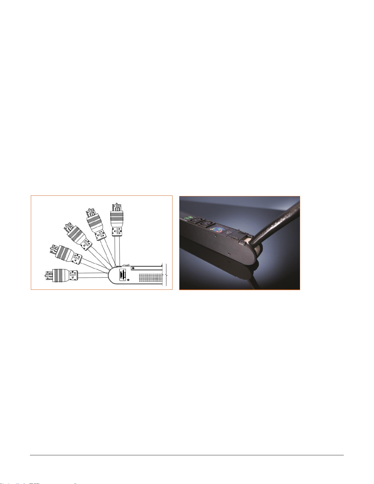
PDU Power Pivot
Server Technology’s PDU Power Pivot flexible infeed provides a simplified power cord routing to the PRO2 unit
with a design that eliminates bend radius issues.
As illustrated below, the PDU Power Pivot capability can deliver a solution for several types of PDU installations
and mountings, setting the correct cord angle for overhead power, offset overhead power, concrete floor, raised
floor, and intra-rack power.
PDU Power Pivot – Flexible Cord Design
Page 8
Switched PRO2 – User Guide
Introducing the PRO2 • 8
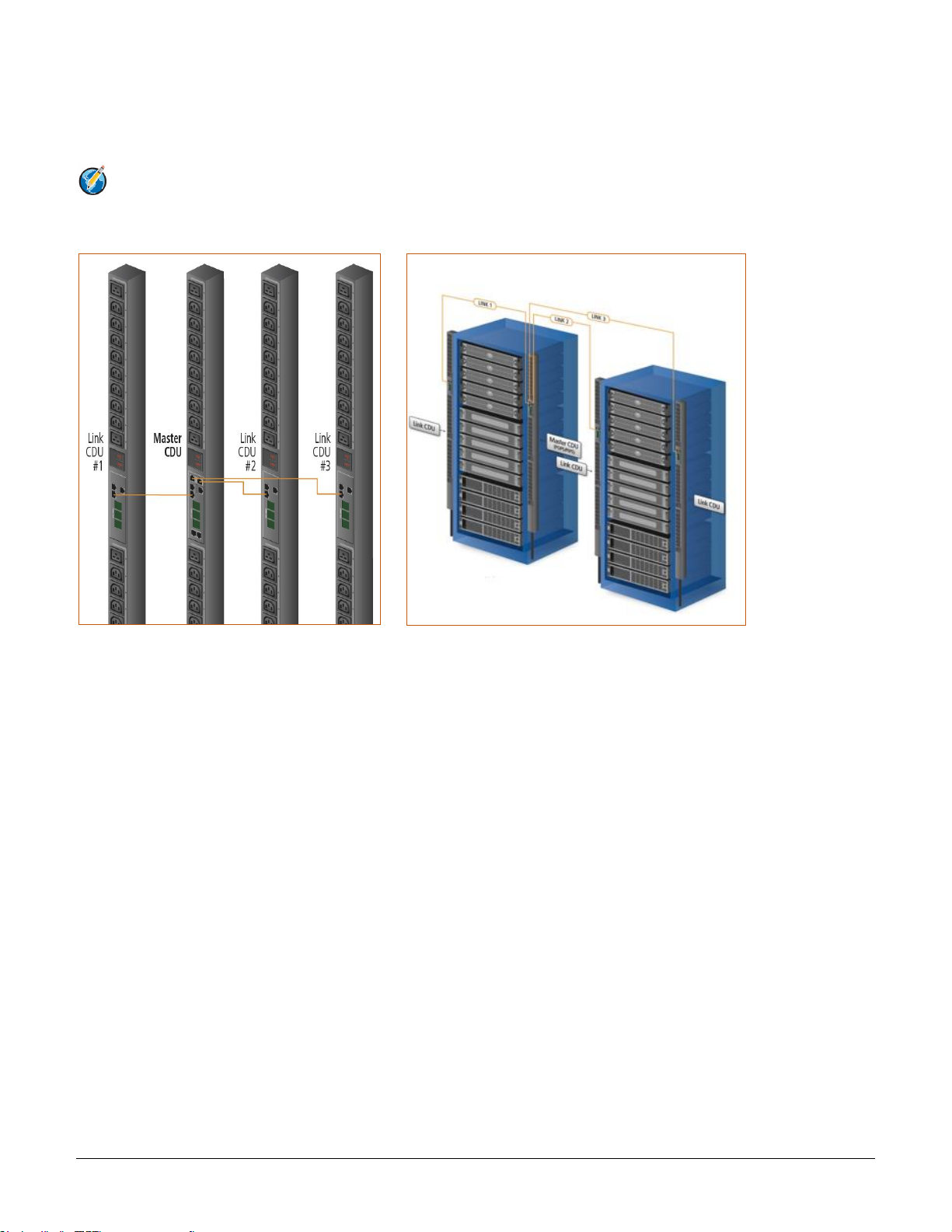
Star Linking Technology
Server Technology’s PRO2 introduces Star Linking technology that supports the optional linking of up to three
expansion (link) units per one PRO2 master unit, allowing a single IP address for multiple cabinets.
Note: The Star Linking feature is available only with PRO2 products.
The following illustrations show multi-linking between separate units and within the cabinet:
Multi-Linked PRO2 Units Multi-Linking View in the Equipment Cabinet
Redundant Power and Communication
The Star Linking arrangement is fault tolerant, with redundant power coming from the first link unit. The
arrangement also offers significant cost reduction as the link units do not require a network card.
Another significant advantage of Star Linking technology is that if power in the master unit is lost, communication
will continue with the other link units – a major improvement over a daisy chain linking configuration.
Outlet Grouping
The multi-linking arrangement allows outlet grouping across the master and three link units.
Cable Length
The maximum cable length allowed from link unit to master unit is 21-feet.
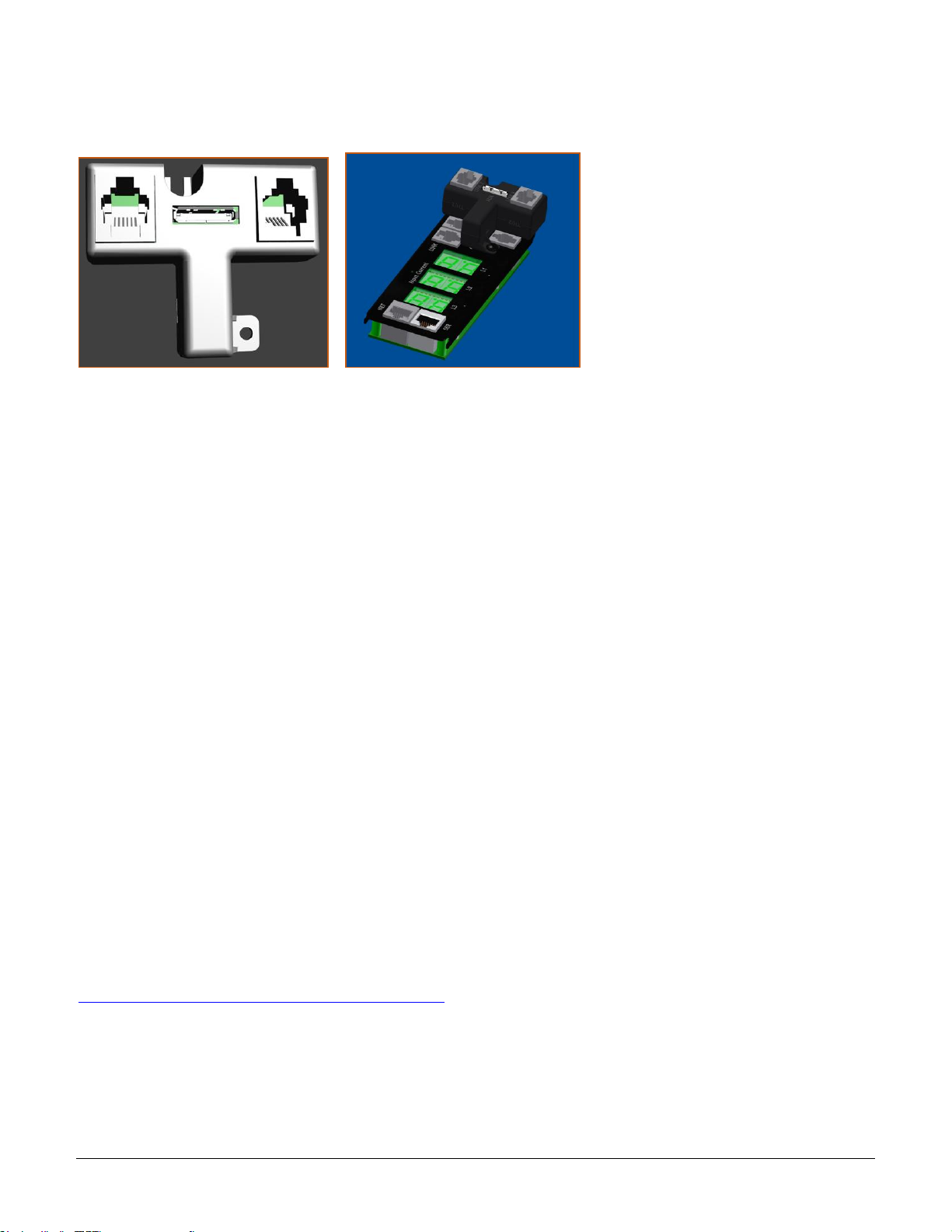
Multi-Linking Module
In the Star Linking arrangement, the first PRO2 link unit connects via the PRO2 link port. However, the second and
third link units in the multi-linking arrangement attach to an optional T-shaped module that connects to the
Bluetooth® port on the PRO2 master unit, while still allowing full functionality for Bluetooth® mobile power
monitoring.
Page 9
Switched PRO2 – User Guide
Introducing the PRO2 • 9
The module and its connection are illustrated as follows:
Multi-Linking Module Connection to Bluetooth® Module Port
Getting Started
The optional Star Linking feature is sold as a separate kit purchased from Server Technology. To use the feature,
contact your sales representative to order the PRO2 Multi-Linking Module Kit, part number KIT-PRO2LINK-01M.
The kit contains:
• 1 link module (labeled to show the 2nd and 3rd link unit)
• 2 linking cables, (21 ft.) 6.4 m
Unit Persistence
Unit Persistence is an internal PRO2 feature that works as follows:
If a link unit is connected to a master unit, and the link unit is disconnected (powered down or accidentally
disconnected), and the master unit is restarted, the link unit will be reported as “Not Found” after the restart
because the link unit is no longer physically connected to the master.
However, the association between the master/link units is retained to allow the continuation of alerts. If the
disconnected link unit is physically re-connected to the master, the “Not Found” status will return to “Normal” status.
To intentionally remove a link unit from connection with a master unit, the link unit must be purged using the Purge
function.
Unit persistence affects all connected PRO2 master/link units whether or not they are connected in a multi-
linking configuration.
Additional PRO2 Resources
For more information about the PRO2, including available product models and an introductory product video, see
Server Technology’s Uptime Solutions page:
http://www.servertech.com/solutions/uptime-solutions
Page 10

Switched PRO2 – User Guide
Introducing the PRO2 • 10
Contact Technical Support
Experience Server Technology's FREE Technical Support
Server Technology understands that there are often questions when installing and/or using a new product. Free Technical
Support is provided from 8 a.m. to 5 p.m. PST, Monday through Friday. After-hours service is provided to ensure your
requests are handled quickly no matter what time zone or country you are located in.
Server Technology, Inc.
1040 Sandhill Drive Tel: 1-800-835-1515 Web: www.servertech.com
Reno, Nevada 89521 USA Fax: 775-284-2065 Email: support@servertech.com
Page 11
Switched PRO2 – User Guide
Introducing the PRO2 • 11
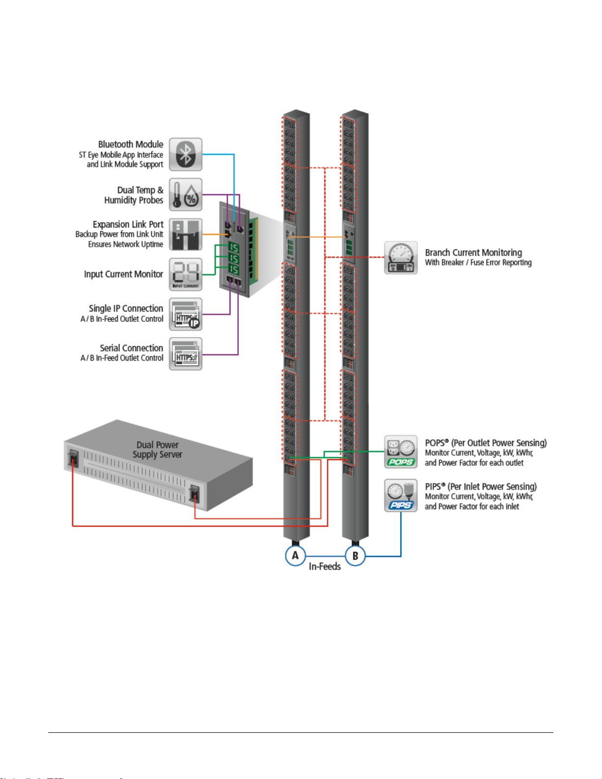
Equipment Overview
The following illustration highlights the key operational areas of the Switched PRO2 unit:
Switched PRO2 – Equipment Overview
Page 12

Switched PRO2 – User Guide
Installing the PRO2 • 12
Chapter 2: Installing the PRO2
Before installing your Switched PRO2 unit, look over the following lists to make sure you have all the items shipped
with the unit, as well as any other items needed for proper installation.
Standard Accessories
Mounting Hardware
• Vertical Models: Two mounting buttons with two M4 (10 mm) screws.
• Horizontal Models: Two removable L-brackets with four M4 screws (for 1U models),
or M5 screws (for 2U models).
Cables/Adapters
• For C2L, C2LG, C2X, C2XG, or SEV models – link cables (6P6C connectors).
• Link units are shipped with a 7-inch link cable and a 14-foot link cable.
Additional Items
• Units with IEC C20 power inlets: input power cords (ordered separately).
Optional Accessories
• Star-Link Module Kit (Part No. KIT-PRO2LINK-01M).
• Temperature/Humidity Sensors (Part No. EMTH-1-1).
• Environmental Monitor (Part No. EMCU-1-1B).
• Water Sensor (Part No. EMWS-1-1, used with EMCU-1-1B).
• Vertical mounting brackets; additional mounting options are available in the Accessories section of
www.servertech.com.
Additional Required Items
• Flathead and Phillip screwdrivers.
• Screws, washers, and nuts to attach the PRO2 unit to your equipment rack.
Page 13
Switched PRO2 – User Guide
Installing the PRO2 • 13
Safety Precautions
This section contains important safety and regulatory information that must be reviewed before installing and
using the Switched PRO2.
Only for installation and use in a
Restricted Access Location in
accordance with the following
installation and use instructions.
This equipment should only be
installed by trained personnel.
Destiné à l'installation et l'utilisation dans le
cadre de Restricted Access Location selon
les instructions d'installation et d'utilisation.
Cet équipement est uniquement destiné
à être installé par personnel qualifié.
Nur für Installation und Gebrauch in
eingeschränkten Betriebszonen gemäß der
folgenden Installations-und
Gebrauchsanweisungen.
Dieses Gerät ist nur für den Einbau
durch Personal vorgesehen.
This equipment is designed to be
installed on a dedicated circuit.
The power supply cord shall be a
minimum of 1.5m (4.9ft) and a
maximum of 4.5m (15ft). If using
an extension power cord, the total
length shall also be no more than
the maximum allowed. The plug is
considered the disconnect device
and must be easily accessible.
Cet équipement a été conçu pour être
installé que un circuit dédié. Le cordon
d’alimentation doit être d’au moins 1,5M et
un maximum de 4,5m. Si vous utilisez un
cordon de rallonge, la longueur totale est
également plus que le maximum autorise.
La prise est considérée comme un
dispositif de coupure et doit être facilement
accessible.
Die Geräte sind für eine Installation an
einer fest zugeordneten Leitung ausgelegt.
Die Stromzuleitung hat eine Mindestlänge
von 1,5m, und hochstens 4,5m. Sollten Sie
ein Verlangerrungsnetzkabel, der
Gesamtlange auch nicht mehr als die
maximal zulassige sein. Der Stecker dient
zur Trennung vom Netz und muss einfach
erreichbar sein.
The dedicated circuit must have
circuit breaker or fuse protection.
PDUs have been designed without
a master circuit breaker or fuse to
avoid becoming a single point of
failure. It is the customer’s
responsibility to provide adequate
protection for the dedicated power
circuit. Protection of capacity equal
to the current rating of the PDU
must be provided and must meet
all applicable codes and
regulations. In North America,
protection must have a 10,000A
interrupt capacity.
Le circuit spécialisé doit avoir un disjoncteur
ou une protection de fusible. PDUs ont été
conçus sans disjoncteur général ni fusible
pour éviter que cela devient un seul endroit
de panne. C’est la responsabilité du client
de fournir une protection adéquate pour le
circuit-alimentation spécialisé. Protection de
capacité équivalant à la puissance de
l'équipement, et respectant tous les codes
et normes applicables. Les disjoncteurs ou
fusibles destinés à l'installation en Amérique
du Nord doivent avoir une capacité
d'interruption de 10.000 A.
Der feste Stromkreis muss mit einem
Schutzschalter oder einem
Sicherungsschutz versehen sein. PDUs
verfügt über keinen Hauptschutzschalter
bzw. über keine Sicherung, damit kein
einzelner Fehlerpunkt entstehen kann. Der
Kunde ist dafür verantwortlich, den
Stromkreis sachgemäß zu schützen. Der
Kapazitätsschutz entspricht der aktuellen
Stromstärke der Geräte und muss alle
relevanten Codes und Bestimmungen
erfüllen. Für Installation in Nordamerika
müssen Ausschalter bzw. Sicherung über
10.000 A Unterbrechungskapazität
verfügen.
Models with unterminated power
cords: Input connector must be
installed by qualified service
personnel. Input connector rating
must meet all applicable codes and
regulations.
Modèles avec cordons d'alimentation non
terminées: Le connecteur d’entrée doit être
installé par un personnel qualifié. Entrée
cote de raccordement doit respecter tous
les codes et règlements électriques
applicables.
Modelle mit nicht abgeschlossenen
Netzkabel: Der Eingangsstecker darf nur
von qualifiziertem Wartungspersonal
installiert werden. Eingangsanschluss
Bewertung müssen alle geltenden und
verbindlichen Normen und Vorschriften
entsprechen.
Do not block venting holes when
installing this product. Allow for
maximum airflow at all times.
Ne bloquez pas les orifices d'aération lors
de l'installation de ce produit. Permettre une
circulation d'air maximale à tout moment.
Achten Sie darauf, dass keine
Belüftungslöcher bei der Installation dieses
Produkts. Damit für maximalen Luftstrom
zu allen Zeiten.
Installation Orientation: Vertical
units are designed to be installed
in vertical orientation.
Installation Orientation: Les unités vertical
sont conçues pour être installées dans une
orientation verticale.
Installationsausrichtung: Vertical Einheiten
sind zur vertikalen Installation vorgesehen.
Always disconnect the power
supply cord before servicing to
avoid electrical shock. For
products with two input power
cords, both must be disconnected
before servicing.
Toujours débrancher le cordon
d'alimentation avant de l'ouverture pour
éviter un choc électrique. Pour les produits
avec deux cordons d'alimentation d'entrée,
les deux doivent être déconnectés avant
l'entretien.
Trennen Sie das Netzkabel, bevor Sie
Wartungsarbeiten Öffnung einen
elektrischen Schlag zu vermeiden. Für
Produkte mit zwei Eingangsstromkabel,
sowohl, müssen vor der Wartung
abgeschaltet werden.
WARNING! High leakage current!
Earth connection is essential
before connecting supply!
ATTENTION! Haut fuite très possible! Une
connection de masse est essentielle avant
de connecter l’alimentation !
ACHTUNG! Hoher Ableitstrom! Ein
Erdungsanschluss ist vor dem Einschalten
der Stromzufuhr erforderlich!
WARNING! Cx-xxE-x units double
pole/neutral fusing
ATTENTION! Les unités Cx-xxE-x Double
Pôle/Fusible sur le Neutre
ACHTUNG!: Cx-xxE-x Zweipolige bzw.
Neutralleiter-Sicherung
ATTENTION! Observe precautions
for handling Electrostatic Sensitive
Devices.
Attention ! Respecter les mesures de
sécurité en manipulant des dispositifs
sensibles aux décharges électrostatiques.
Achtung! Vorsichtshinweise zur
Handhabung elektrostatisch empfindlicher
Geräte beachten.
Products rated for 240/415VAC
may be fitted with a plug that is
rated for a higher voltage. Caution
must be taken to assure that the
rating of the unit and the supply
voltage match.
Les produits prévus pour 240/415VAC peut
être équipé d'un bouchon qui est conçu
pour une tension plus élevée. Des
précautions doivent être prises pour assurer
que la cote de l’unité et la tension
d’alimentation correspond.
Produkte die für 240/415VAC zugelassen
sind können mit einem Stecker der für eine
höhere Spannung ausgestattet sein.
Vorsicht ist geboten, um sicherzustellen,
dass die erlaubten Betriebswerte des
Gerätes und der Versorgungsspannung
zueinander passen.
Page 14
Switched PRO2 – User Guide
Installing the PRO2 • 14
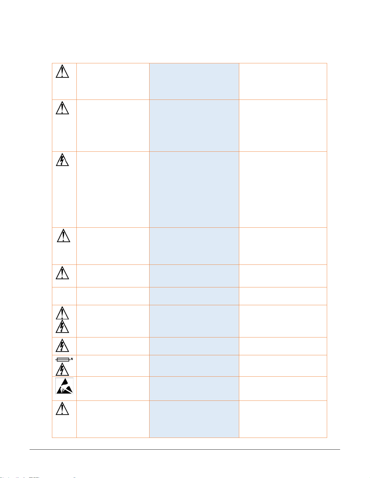
Input Power Cord Retention Options for PRO2s with IEC C20 Inlets
Determine which Detachable Input Cord was supplied with your PRO2 unit:
For the following Detachable Input Cords with the self-locking
IEC C19 feature, follow Procedure A below.
PTCORD-L1, PTCORD-L2, PTCORD-L3, PTCORD-L5, PTCORD-L6, or
PTCORD-L7.
For the following Detachable Input Cords, follow Procedure B below.
PTCORD-1, PTCORD-2, PTCORD-3, PTCORD-4, PTCORD-5, PTCORD-6,
or PTCORD-7.
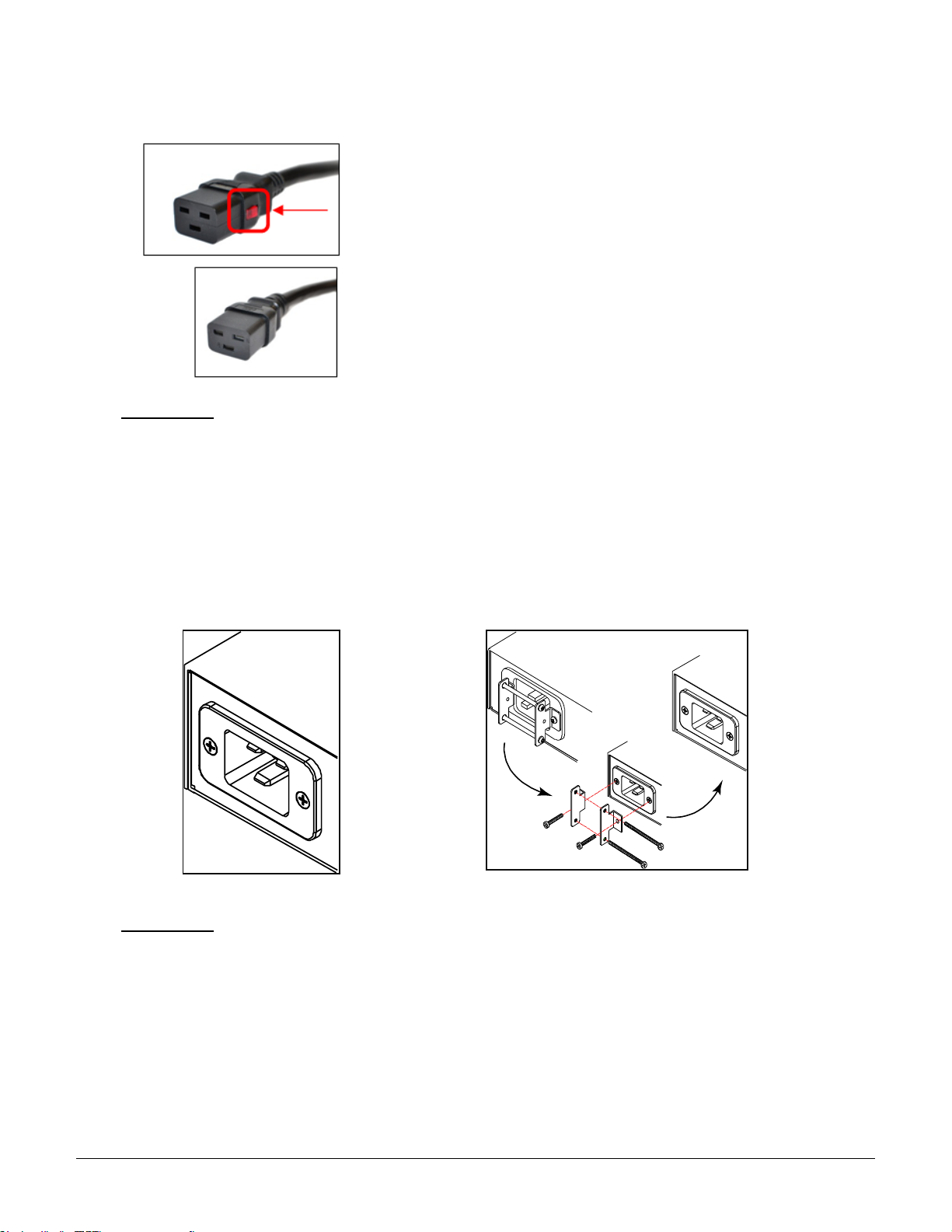
Procedure A
If the PRO2 was supplied with a Detachable Input Power Cord with a self-locking IEC C19, install it directly
into the C20 inlet.
1. Verify the Retention Bracket Assembly (part number KIT-0016) is not installed.
a. If KIT-0016 is installed, remove the two screws attaching the bracket to the IEC 60320 C20 inlet
to the enclosure.
b. Remove the Retention Bracket Assembly.
c. Re-attach the two screws to the IEC C20 and securely tighten.
2. Push the C19 from the Detachable Input Cord firmly into the C20 inlet to ensure it is properly seated.
C20 Inlet Without Retention Bracket Assembly KIT-0016 Retention Bracket Assembly
Procedure B
If the PRO2 was supplied with a Detachable Input Power Cord without the self-locking C19 feature, install
with the Retention Bracket Assembly (part number KIT-0016), followed by the power cord.
1. Remove the two screws attaching the IEC 60320 C20 inlet to the enclosure.
2. Assemble and attach the Retention Bracket to the enclosure as shown
3. Connect the power cord. Ensure the C19 is fully seated against the C20 inlet. (It may be necessary
to loosen some of the Retention Bracket Assembly screws to allow the C19 plug to be properly
installed.)
4. Tighten the Retention Bracket Assembly to restrain the power cord.
Page 15
Switched PRO2 – User Guide
Installing the PRO2 • 15
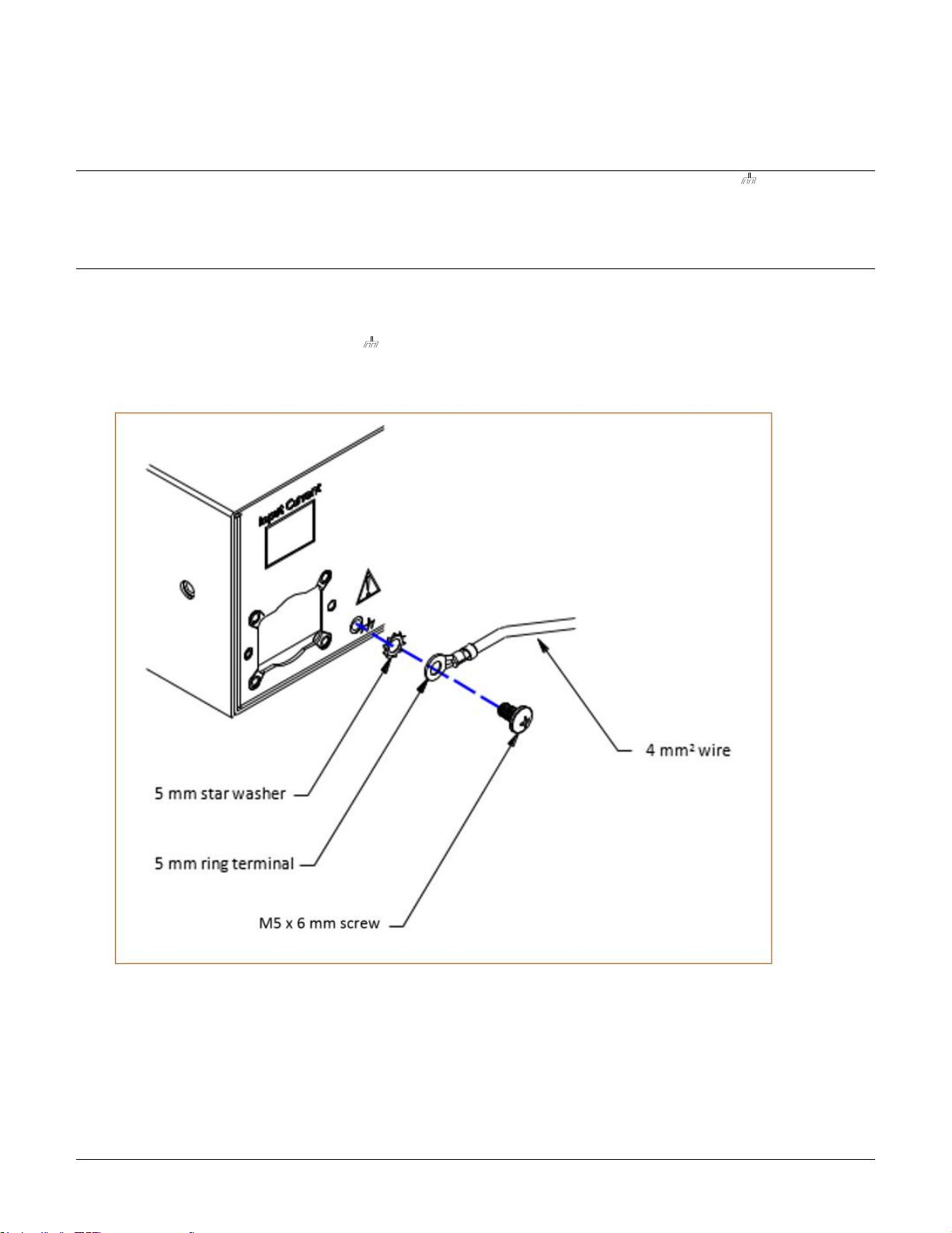
Attaching Safety Earth Ground Connection
Server Technology PDUs are supplied with an external safety ground connection to provide an alternate ground path for fault
currents, and to maintain the same ground reference between it and the equipment rack.
NOTE: The auxiliary external ground location may vary. Most PDUs will have it located near the power cord entry located near the symbol.
User-supplied materials:
• One 5 mm internal (or external) tooth star washer;
• One 4.0 mm
2
(10 AWG) wire with 5 mm ring terminal;
• One metric M5 x 6 mm coarse pitch screw.
Instructions:
1. Connect one end of the ground wire to the equipment cabinet or local ground.
2. Locate the PDU external ground near the symbol.
3. Connect the other end with a ring terminal and a M5 screw to the PDU external ground. To ensure proper grounding
to the chassis, use a star washer between the ring terminal and the PDU.
Page 16
Switched PRO2 – User Guide
Installing the PRO2 • 16
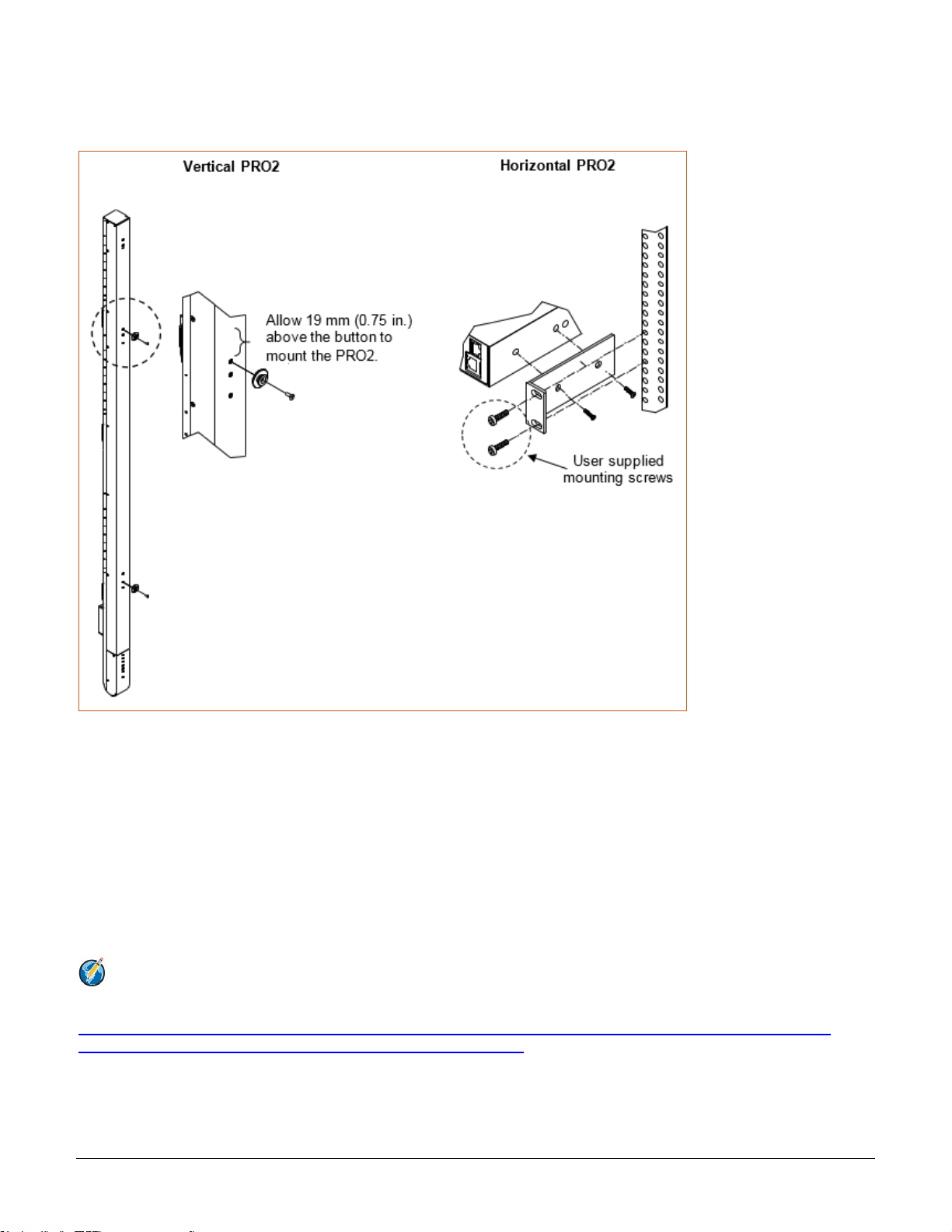
Mounting the PRO2 Unit
The following illustration shows how to mount the PRO2 unit in vertical or horizontal orientation:
Horizontal/Rack
1. Select the appropriate bracket mounting points for proper mounting depth within the rack.
2. Attach the L-brackets to these mounting points with two screws for each bracket.
3. Install the enclosure into your rack, using the slots in each bracket. The slots allow about 6 mm (0.25 inch)
of horizontal adaptability to align with the mounting holes of your rack.
Vertical
PRO2 units are supplied with button mounting kit(s). Distribute the buttons vertically and attach to the PRO2 as
appropriate for the cabinet. An additional 19 mm (0.75 inch) of clearance is required at the top of the PRO2 to allow
the button to mount into the keyholes.
Note: For more information about horizontal/vertical mounting options for the PRO2, see the Server
Technology PDU Mounting Bracket Catalog:
https://cdn10.servertech.com/assets/documents/documents/246/original/Mounting_Bracket_Catalog.2015-09-
25.pdf?1453767377#_ga=1.196494891.640622464.1488848222
Page 17
Switched PRO2 – User Guide
Installing the PRO2 • 17
Attaching the Link Unit
Connect the PRO2 link unit with the provided 6P6C crossover cable at the link port on the PRO2 unit. The overall
length of the crossover cable should not exceed 25 feet.
Connecting to the Power Source
On PRO2 units with a rating ≥ 24 A, the input power cord is attached to the base of the unit. On PRO2 units with a
total maximum output < 24 A, you may need to attach the power cord to the unit before connecting the unit to the
power source.
To attach a power cord to the unit:
1. Plug the female end of the power cord firmly into its connector on the PRO2.
2. If using the Retention Bracket Assembly (Part No. KIT-0016), use a screwdriver to tighten the two screws
on the retention bracket.
To connect to the power source:
1. Plug the male end of the power cord into the AC power source.
Connecting Devices
To avoid the possibility of noise due to arching:
1. Keep the on/off switch on the device in the off position until after it is plugged into the outlet.
2. Connect the devices to the PRO2 outlets.
Note: Server Technology recommends even distribution of attached devices across all available outlets to
avoid exceeding the outlet, branch, or phase limitations.
Always disconnect ALL power supply cords before opening to avoid electrical shock.
Afin d’éviter les chocs électriques, débranchez TOUTES les cables électrique avant d’ouvrir
Vor dem Offnen immer Netzleitung abziehen um elektrischen Schlag zu vermeiden.
Connecting the Sensors
The PRO2 is equipped with two mini RJ11 temperature/humidity ports for attachment of the temperature/humidity
sensors. Attach the mini RJ11 plug of the sensor(s) to the appropriate temperature/humidity port.
Connecting to the Unit
Connection can be made with a serial (RS232) port or with an Ethernet port, as described:
For the Serial (RS232) Port:
The PRO2 is equipped with an RJ45 serial RS-232 port – for attachment to a PC or networked terminal server –
using the supplied RJ45-to-RJ45 crossover cable and the RJ45-to-DB9F serial port adapter, as required.
For the Ethernet Port:
The PRO2 is equipped with an RJ45 10/100Base-T Ethernet port for attachment to an existing network. This
connection allows access to the PRO2 unit via Telnet or Web.
Page 18

Switched PRO2 – User Guide
Installing the PRO2 • 18
Network Defaults
The PRO2 is configured with the following network defaults to allow unit configuration out-of-the-box through either
Telnet or Web. However, note that when the PRO2 is installed on a DHCP-enabled network, the following network
defaults do not apply because the PRO2 ships with DHCP support enabled by default.
Network Defaults (for non-DHCP-enabled networks):
• IP Address: 192.168.1.254
• Subnet Mask: 255.255.255.0
• Gateway: 192.168.1.1
Reconfigure the Network Connection
A local PC network connection must be reconfigured as follows. For detailed instructions about this connection,
contact your system administrator. Note that a restart of the system may be required for the network reconfiguration
to take effect.
• IP Address: 192.168.1.x (where “x” is 2-253)
• Subnet Mask: 255.255.255.0
Page 19

Switched PRO2 – User Guide
Getting Started with the Firmware • 19
Chapter 3: Getting Started with the Firmware
This chapter introduces several key features of the firmware (version 8.0x or later) for the PRO2.
Note: Firmware, version 8.0, for the PRO2 product is not compatible with other Server Technology
Rack Power Distribution Unit products. There is no upgrade path from earlier PDI products to PRO2
products.
On-Board File System
The firmware Web Interface provides an embedded file system to give quick access to system configuration files,
as well as the on-board and downloadable Sentry4-MIB and OID Tree for the PRO2, eliminating website MIB/OID
downloads.
The page also allows GUI-based file uploads (without FTP) for system, configuration, and firmware versions.
However, all PRO2 configuration/system files, MIB, and OID Tree can also be accessed via FTP/SFTP.
Intuitive and Consistent Terminology
The design of the firmware includes intuitive and soft-mapped naming conventions between the interfaces (Web
and CLI) and the PRO2 product. For example, the firmware GUI areas (cords, lines, phases, over-current
protectors, branches, outlets, sensors, etc.) match the same areas designed in the PRO2 hardware architecture.
Outlet numbers are named 1-n sequentially and the outlet name is not tied to infeeds or branches. Input cords are
also simply named 1-n sequentially (like 1-24), no longer 1-n for each phase (like XY 1-8, YZ 1-8, ZX 1-8).
Also, firmware naming formats match the exact silkscreened names on the hardware unit.
Outlet Grouping
An outlet group is named group with a collection of PRO2 outlets assigned to the group. Outlet groups can be
granted access to selected outlets by the administrative user (via the Web interface or CLI), and outlet activity by
group can be monitored on a separate Web interface page for outlet group monitoring.
Setting Thresholds
When setting threshold values, the PRO2 firmware allows expanded alerting capabilities. Threshold values can be
set by the administrative-user for multiple low/high warning/alarm levels (and threshold hysteresis), as listed below
in the following PRO2 areas.
Every item shown in the following list – for which a threshold can be set – also has a corresponding Monitoring
page for viewing the item’s current threshold values and operational status.
• Branch current (low and high).
• Cord power (low and high), cord apparent power (low and high), cord power factor (low), 3-phase out-of-
balance (high).
• Line current (low and high).
• Outlet current (low and high), outlet power (low and high), outlet power factor (low).
• Phase voltage (low and high), phase power factor (low).
• Temperature sensor (low and high).
• Humidity sensor (low and high).
• Analog-to-Digital (ADC) sensor (low and high) – if an EMCU is connected to the PRO2 unit.
Page 20

Switched PRO2 – User Guide
Getting Started with the Firmware • 20
PRO2 Dashboard View
The firmware Overview > System page provides a fast and high-level view of the overall condition of the PRO2
unit. The sub-system status view shows the current operational state of individual PRO2 (units, cords, lines, etc.).
The color-coded status icon for each area is hot-linked to the corresponding monitoring page to show the operating
details behind the status, for example:
Page 21
Switched PRO2 – User Guide
Getting Started with the Firmware • 21
The User Interfaces
The Switched PRO2 offers two built-in user interfaces:
• Web interface (GUI) accessed via HTTP-enabled Ethernet connections.
• Command Line Interface (CLI) for serial and Telnet connections.
Both interfaces allow power monitoring of PIPS/POPS data points, temperature/humidity measurements,
system/network configuration, outlet control, ST Eye Bluetooth® connection, user account management, and
numerous other operations for the Switched PRO2.
Either interface can be used as preferred; most firmware operations can be performed on GUI screens or by CLI
commands on the command line. When using either interface, the availability of firmware functions for your user
login account depends on your current user access rights as granted by the system administrator.
Usernames and Passwords
The Switched PRO2 is shipped with one default administrative user account (username/password is admn/admn).
There is no “i” in the admn username or password.
Only an administrative user can manage user accounts, such as creating new user accounts, removing user
accounts, and changing user passwords.
The PRO2 supports a maximum of 112 defined user accounts with the following restrictions:
User Account
Length
Case-Sensitive
Spaces Allowed
Usernames
1-32 characters
No
No
Passwords
1-32 characters
Yes
Yes
Note: For security, Server Technology recommends first creating a new user account with administrative
rights, and then removing the default admn account.
Page 22

Switched PRO2 – User Guide
Getting Started with the Firmware • 22
User Access Rights
The following table defines the user rights granted by the administrative user for access to PRO2 operations using
either the Web GUI or the Command Line interface (CLI). Only the options for which the user has access rights will
be available in the firmware for the user.
User Access Level
(highest to lowest)
Description
Administrator
Administrative user; full access for all configuration, user management, all outlet power control
actions (On, Off, Reboot), status, and serial/pass-thru ports.
Power User
Full access for all outlet power control actions (On, Off, Reboot), status, and serial/pass-thru
ports. Note: The Power User does not have access to user management.
User
Partial access for outlet power control actions (On, Off, Reboot), status, and pass-thru of
assigned outlets, outlet groups, and serial/pass-thru ports.
Reboot-Only User
Partial access for outlet power control actions (Reboot), status, and pass-thru of assigned
outlets, outlet groups, and serial/pass-thru ports.
On-Only User
Partial access for outlet power control actions (On), status, and pass-thru of assigned outlets,
outlet groups, and serial/pass-thru ports.
View-Only User
Partial access for status and pass-thru of assigned outlets, outlet groups, and serial/pass-thru
ports.
The administrative user can also grant administrative-level rights to other user accounts, allowing the PRO2 unit to
have more than one administrative user.
Administrative access rights cannot be removed from the default admn user account until an administrative user
grants administrative access rights to another user account.
To use administrative commands, the user must be granted administrative user access rights.
Page 23

Switched PRO2 – User Guide
Getting Started with the Firmware • 23
IPv4/IPv6 Support
Note: Throughout the Web and CLI firmware interfaces, both IPv4 and IPv6 formats are accepted
wherever a hostname or IP address is provided.
Server Technology uses IPv6 “dual stack” support in the firmware PRO2 product line. IPv6 has been designed to
succeed IPv4 as the dominant communications protocol for internet traffic, to avoid depletions of the IPv4 address
space, and to allow more IP address growth. Many devices already in use support IPv6.
IPv6 has several new operational methods:
• Static IPv6 Address: The IPv6 equivalent of Static IPv4.
• DHCPv6 Address: The IPv6 equivalent of a DHCP IPv4 address, also known as a “stateful” auto-
configuration of DHCPv6.
• IPv6 Stateless Auto-Configured Address – (RFC 4862): An automatically-generated unique link-local IPv6
address used for client based configurations. This address is always present in the Server Technology dual
stack and cannot be disabled.
• DHCPv6 Stateless Auto-Configured Address – (RFC 3736): A “stateless” Dynamic Host Configuration
Protocol (DHCP) service for IPv6 (DHCPv6). This address is used by nodes to obtain configuration
information, such as addresses of DNS recursive name servers that do not require the maintenance of any
dynamic state for individual clients.
Protocol Support for PRO2 Firmware
IPv6 and IPv4 Protocols:
The PRO2 firmware supports the following network IPv6 and IPv4 protocols:
• DNS Ping
• FTP (or SFTP) Server SNMPv1/2/3
• FTP (or SFTP) Updates SNTP
• HTTP or HTTPS
• SMTP
• Static IPv6 DHCPv6 (stateless and stateful)
• Syslog SNMPv1/2/3 Traps
• Telnet SSH
IPv4-Only Protocols:
The PRO2 firmware supports the following network IPv4-only protocols:
• Cisco EnergyWise
• LDAP
• Load Shedding *
• RADIUS *
• TACACS+
* = may work with IPv6 addresses, but not tested.
Page 24

Switched PRO2 – User Guide
Getting Started with the Firmware • 24
Network-Enabled Modes
Notes:
• For all network-enabled modes described below, the PRO2 will set an auto-configured IPv6 address, and if
IPv6 router announcements are active, a stateless DHCP IPv6 address will also be set. Further, in all
network-enabled modes, at least one IPv4 or one IPv6 address will be active.
• For maximum backward compatibility, the default network mode is “IPv4 only”.
Descriptions for the network-enabled modes:
• Network disabled – No IPv4 or IPv6 addresses available.
• IPv4 only, DHCP disabled (static IPv4) – If the IPv4 Static Address and Net Mask of the PRO2 are valid,
they will be set.
• IPv4 only, DHCP enabled (DHCP IPv4) – The PRO2 will try to resolve an IPv4 DHCP address. If a DHCP
address cannot be obtained after 90 seconds, the PRO2 can: (1) optionally fall back to its static IPv4
settings, or (2) indefinitely wait to acquire an address based on DHCP configuration settings. This setting
is the default.
• Dual IPv6/IPv4, DHCP disabled (static IPv6/IPv4) – If the IPv6 Static Address and prefix of the PRO2 are
valid, they will be set. Otherwise, the PRO2 will attempt to use DHCPv6 to obtain an IPv6 address. In
addition, if the IPv4 Static Address and Net Mask of the PRO2 are valid, they will be set.
• Dual IPv6/IPv4, DHCP enabled (DHCP IPv6/IPv4) – The PRO2 will try to resolve both its IPv6 and IPv4
addresses by DHCP. If both DHCP requests are answered, the primary DNS server of the PRO2 will
become the primary IPv6 DNS server, and the secondary DNS server of the PRO2 will become the
primary IPv4 DNS server. If only one of the DHCP requests is answered, the DNS servers of the PRO2 will
map to the primary and secondary DNS server from that request. If a DHCP address cannot be obtained
after 90 seconds, the PRO2 can: (1) optionally fall back to its static IPv4 and/or IPv6 settings, or (2)
indefinitely wait to acquire an address based on DHCP configuration settings.
Page 25

Switched PRO2 – User Guide
Getting Started with the Firmware • 25
Viewing Network Status
You can obtain the IPv6 network status through the firmware Web Interface or Command Line Interface (CLI). For
the CLI, use the show network command as follows:
Switched CDU: show network
Network Configuration
State: Static IPv4 Network: Dual IPv6/IPv4
Link: Up Negotiation: Auto
Speed: 100 Mbps Duplex: Full
MAC: 00-0A-9C-60-0029
AutoCfg IPv6: FE80::20A:9CFF:FE60:29/64
IPv4 Address: 10.1.2.65 Subnet Mask: 255.255.0.0
IPv4 Gateway: 10.1.1.1
DNS1: 10.1.5.133
DNS2: 10.1.5.134
Static IPv4/IPv6 Settings
IPv6 Address: ::/64
IPv6 Gateway: ::
IPv4 Address: 10.1.2.65 Subnet Mask: 255.255.0.0
IPv4 Gateway: 10.1.1.1
DNS1: 10.1.5.133
DNS2: 10.1.5.134
DHCP Settings
DHCP: disabled
FQDN: enabled [sentry-600029]
Boot Delay: disabled
Static Fallback: disabled
Network Services
FTP Server: enabled Port: 21
FTP Updates: disabled Port: 21
SSH: enabled Port: 22 Auth: Password, Kb-Int
Telnet: enabled Port: 23
HTTP: enabled Port: 80
HTTPS: enabled Port: 443 Installed Cert: Self Generated
User Cert: Disabled Stored Files: None
User Passphrase: (none)
SNMPv1/2: enabled Port: 161 TrapPort: 162
SNMPv3: disabled Port: 161 TrapPort: 162
SPM Access: enabled
Note: The fields IPv4 Address, IPv4 Subnet Mask, IPv4 Gateway, DNS1, and DNS2 are equivalent to existing
PRO2 IPv4 settings except that current network settings and static settings are displayed separately.
This allows you to view both static configuration settings and active network settings that can be obtained
using DHCP. The DNS addresses may be in IPv4 or IPv6 (based on RFC4291) format at this time.
Page 26
Switched PRO2 – User Guide
Using the Web Interface • 26
Chapter 4: Using the Web Interface
This chapter shows how to work with the firmware GUI (version 8.0x or later) for the PRO2.
Logging In
Logging into the Web interface directs the Web client to the configured IP address of the Switched unit.
To login by Web interface
In the firmware login window, provide a valid username and password, and click OK.
If you enter an invalid username or password, you will be prompted again.
You are given three attempts for a valid username/password combination, after which the session ends and a
protected page will be displayed
Note: The default firmware username/password is admn/admn. There is no “i” in admn.
Quick Tour of the GUI
The web interface provides web-based access to the firmware for the Switched unit. The interface is designed with
three major screen sections shown in the following screen example:
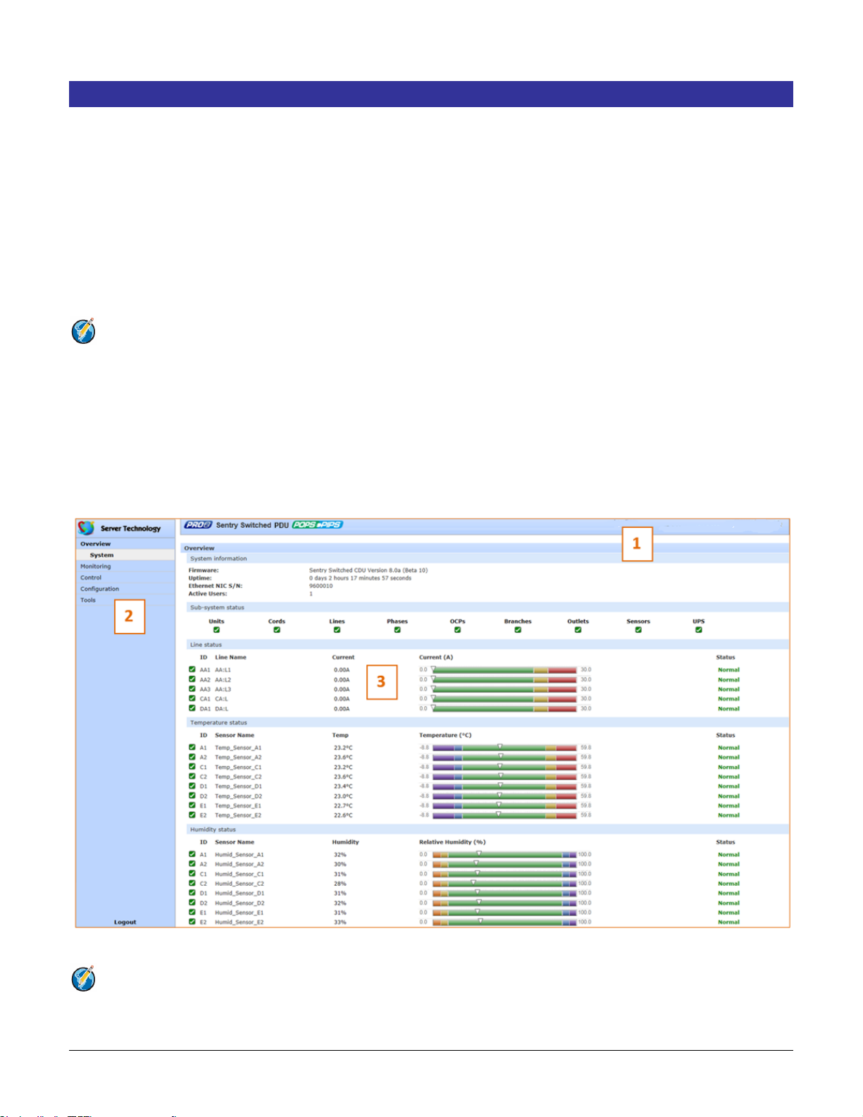
1. System Header: Displays PRO2 description/location, IP address, and user/access level.
2. Navigation Bar: Provides access to PRO2 power monitoring, control actions, and configuration.
3. Details Window: Shows control/status information based on option selected in navigation bar.
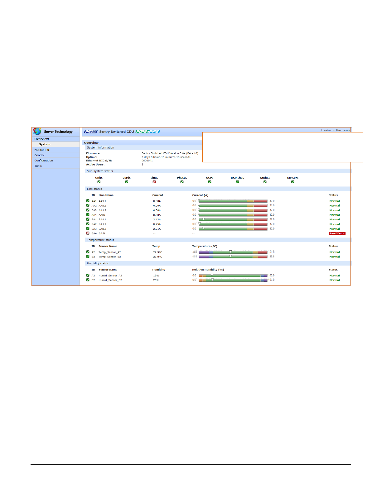
Example of PRO2 Firmware Web Interface: Overview > System Page
Note: The optional blinking PRO2 location string (IP address) in the System Header may not work with all web
browsers.
Page 27
Switched PRO2 – User Guide
Using the Web Interface • 27
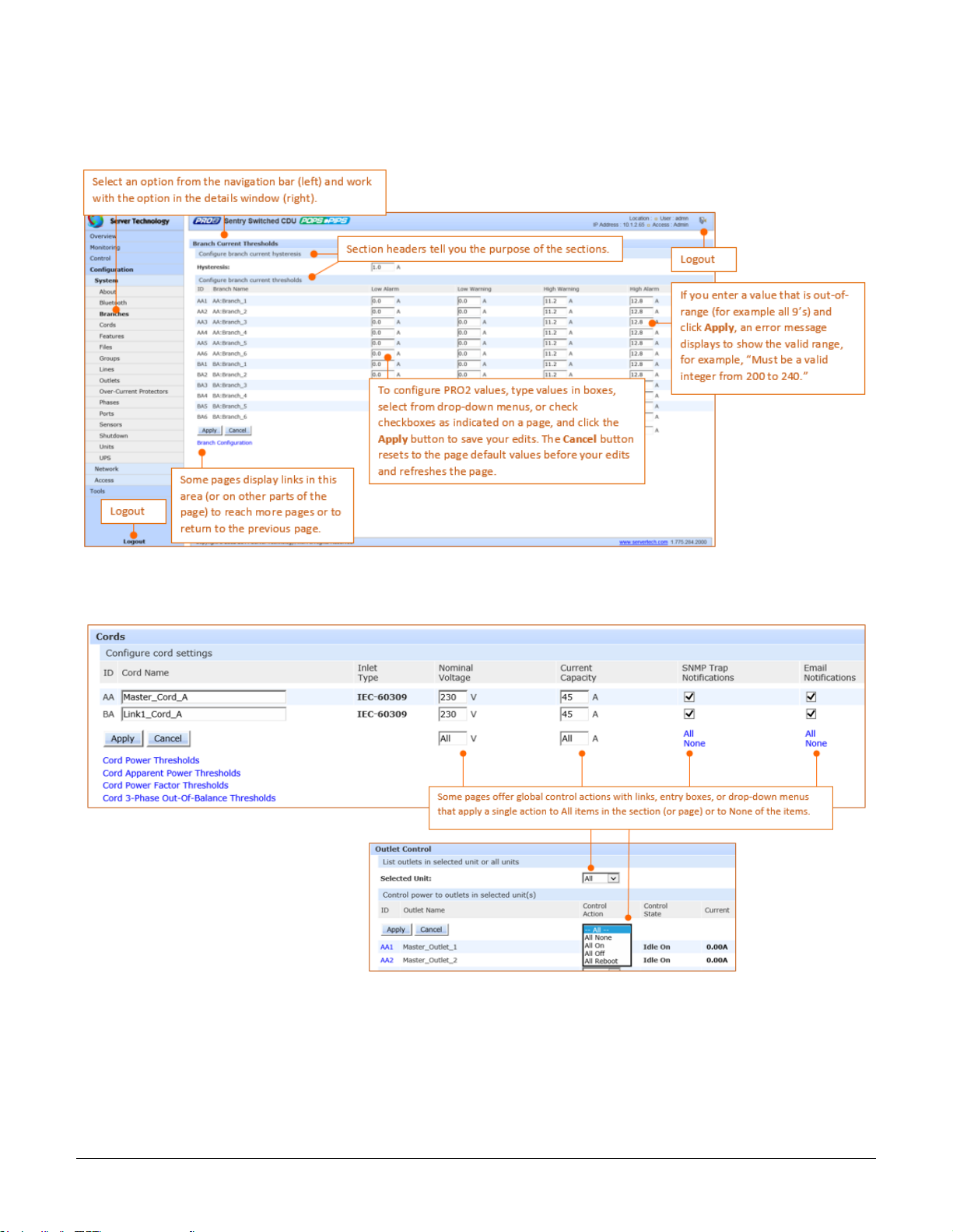
Working with the Pages
Using a configuration page:
Using the All or None global action:
Page 28

Switched PRO2 – User Guide
Using the Web Interface • 28
Summary of the GUI Options
Overview
The Overview > System option is the first stop for high-level and fast monitoring of major PRO2 operational areas.
The page displays a quick view of color-coded icons showing current status of the units, cords, branches, lines,
phases, sensors. Click an icon for the related monitoring page to view the metrics behind the status.
The System page also shows color-coded graphs for the operational status of line current and
temperature/humidity sensor readings.
General system information displays on the page to show firmware version in use, uptime data, Ethernet NIC serial
number, and current number of active users.
The System page dynamically updates status and threshold values with a full-screen refresh to reflect the latest
PRO2 details for instant assessment and response.
Monitoring
The Monitoring option provides viewing of dynamically updated metrics for the PRO2 operational areas that have
the highest power impact on the unit and the data center.
The design of the GUI monitoring pages follows the major areas in the hardware architecture of the PRO2,
providing a separate and detailed page for the overall status of units, cords, lines, OCPs, branches, outlets, groups,
and sensors.
Each system object for which a threshold can be configured – such as line current and phase voltage – has a
corresponding monitor page that displays up-to-the-minute power metrics.
Many metrics are presented on the pages in color-coded graphs for at-a-glance monitoring. A regular full-page
refresh dynamically updates theses details to reflect the current condition of the PRO2, providing the opportunity for
instant assessment and fast response to critical system issues.
Control
The Control option allows the issuing of control actions On, Off, and Reboot for all PRO2 individual outlets, global
outlets, and named outlet groups.
Outlet details are also available by individual outlet to provide the outlet’s general identification, socket type,
capacity, operational state, power factor, as well as color-coded graphs for current and power.
A PRO2 unit with Per Outlet Power Sensing (POPS) technology will also display values for current capacity used
and reactance.
Configuration
The Configuration option allows administrative access to all options for setting PRO2 values. The pages are
organized into three major areas of configuration:
• System (options for PRO2 hardware areas)
• Network (options for setting up network protocols)
• Access (options for local/remote user access and management)
Page 29

Switched PRO2 – User Guide
Using the Web Interface • 29
Network
The Network option provides network setup options for the protocols supported by PRO2: DHCP/IP, Email/SMTP,
FTP/SFTP, HTTP/HTTPS, LDAP, RADIUS, SNMP, SNTP, Syslog, TACACS+, and Telnet/SSH. The Network
option only allows the administrator to set up network protocol parameters. To configure how the PRO2 user uses
the network and system, see the Access option.
Access
The Access option determines how a PRO2 user works with the network and system by configuring the options
related to a user: authentication, privilege levels, user access to the unit, and additional functions for individual local
users and user groups. The Access option only allows the administrator to determine how the PRO2 user uses the
network and system. To set up network protocol parameters, use the Network option.
Tools
The Tools option is a collection of several utility options for miscellaneous system actions: changing user password,
pinging other network devices, viewing the system/debug log, and uploading new firmware versions. Also included
are several options for rebooting the PRO2, resetting the PRO2 to factory defaults, and restarting the PRO2 with
user preferences.
Page 30
Switched PRO2 – User Guide
Using the Web Interface • 30
Overview (Viewing the System Dashboard)
The System page of the Web interface is the first stop for high-level and fast monitoring of major PRO2 operational
areas. The page displays a quick view of color-coded icons showing current status of the units, cords, branches,
lines, phases, sensors. Click an icon for the related monitoring page to view the metrics behind the status.
The System page also shows color-coded graphs for the operational status of line current and
temperature/humidity sensor readings.
General system information displays on the page to firmware version in use, uptime data, Ethernet NIC serial
number, and current number of active users.
The System page dynamically updates status and threshold values with a full-screen refresh to reflect the latest
PRO2 details for instant assessment and response.
How to Read the Metrics
The color-coded status icons and graphs on the System page update dynamically (normal-green, warning-yellow,
critical-red) with the latest metrics of the unit, line status, and temperature/humidity sensor status.
About Auto-Scaling
The displayed graphs reflect the internal function of auto-scaling. This means that if the threshold range of values
changes for the graph, the graph will auto-scale to the appropriate range, allowing the graphs to still present
relevant and consistent information.
What To Look For
The dynamic performance of the System page is essential for monitoring new PRO2 installation or watching for
power distribution changes in hi-density environments. High-level status information on the System page gives the
chance to correct of an operating condition before it affects the entire device network.
System administrators and power users can also view the System graphs to quickly identify thermal and humidity
issues that might otherwise escalate to infrastructure repairs if left unchecked.
The sub-system icons across the page match the left-pane
Monitoring options. Click either the icon name or select a
monitoring option to display the related monitoring page.
Page 31

Switched PRO2 – User Guide
Using the Web Interface • 31
Overview > System Page Definitions
The System page uses the following fields and definitions:
Field
Description
ID
System-assigned internal name that cannot be changed.
Name
User-defined descriptive name for each line or temperature/humidity sensor.
Current, Temp,
Humidity
Current state of the reported input load (in amps), current temperature (temperature scale C
F, as configured), or current percent of relative humidity (%RH).
Low Limit
User-defined low limit of the load, temperature, or humidity graph. These values depend on
the sensor limitation and cannot be set by the user. For example, a 0ºC low limit would be
displayed as 0 for a temperature sensor graph in Celsius.
High Limit
Displays the high limit of the load, temperature, or humidity graph. For the
temperature/humidity sensors, these values depend on the physical sensor limits and cannot
be set by the user. For example, a 100ºC high limit would be displayed as 100 in the high limit
in a (Celsius) temperature sensor graph.
Sensor Graph and
Level Indicator
The horizontal sensor graph shows current operating conditions with color-coded icons,
described in the following table, Status Icons and Descriptions”. The level indicator
appears in the graph to indicate relative position of the current data value with respect to the
minimum (low limit) and maximum (high limit) values displayed at the left end and right end of
the graph.
Status Icons and Descriptions
The System page uses the following icons to report current operating conditions:
Icon
Status
Description
Reading
Unit is reading a new or restored sensor.
Normal
Normal operation.
Low/High Warning
Current value outside user-configured threshold range.
Low/High Alarm
Current value outside user-configured threshold range.
Lost
Connection has been lost to a sensor that was previously detected.
Read Error
Error polling data from the PRO2.
Page 32

Switched PRO2 – User Guide
Using the Web Interface • 32
Sensor Graph Color-Coding
The sensor graph colors change dynamically to communicate operating conditions:
For Line (Load) Status:
Green = Normal
Yellow = low warning/high warning (threshold configured by user)
Red = low alarm/high alarm (threshold configured by user)
Configure line current thresholds and threshold hysteresis at Configuration > System > Lines.
For Temperature Status:
Violet = coldest; low alarm (threshold configured by user)
Blue = cold; low warning (threshold configured by user)
Green = acceptable temperature range
Yellow – warm; high warning (threshold configured by user)
Red = hot; high alarm (threshold configured by user)
Configure low/high temperature thresholds and threshold hysteresis at Configuration > System > Sensors.
For Humidity Status:
Violet = wettest; high alarm (threshold configured by user)
Blue = wet; high warning (threshold configured by user)
Green = acceptable percentage of relative humidity
Yellow = dry; low warning (threshold configured by user)
Red = driest; low alarm (threshold configured by user)
Configure low/high temperature thresholds and hysteresis at Configuration > System > Sensors.
System Information
This section of the Summary page provides general information:
• Firmware: Current firmware version
• Uptime: Cumulative time the PRO2 has been up and running since the last unit restarted. Shows
continuous, real-time system updates with an approximate 5-second automatic refresh. A manual refresh is
not required.
• Ethernet NIC S/N: The serial number of the PRO2 derived from the Ethernet NIC.
• Active Users: Number of active user sessions accessing the firmware. These sessions include serial,
Telnet, SSH, and Web sessions. Also shows sessions that an unauthorized user may be attempting to
access the system. The number changes instantly as the number of active user sessions changes. A total
of 4 concurrent web user sessions are allowed (HTTPS or HTTPS).
Note: Depending on the web browser, multiple web accesses from the same machine are often
considered as one active user.
Page 33

Switched PRO2 – User Guide
Using the Web Interface • 33
Sub-System Status
This Sub-System section of the Summary page provides a quick status view of the current operational state of
major PRO2 areas (units, cords, branches, etc.) showing a color-coded status icon.
Also provided is a link from each of the sub-system areas to the related monitoring page:
Click the name of one of the PRO2 system areas to display
its corresponding Monitoring page.
View detailed operating status on the Monitoring page.
Page 34

Switched PRO2 – User Guide
Using the Web Interface • 34
Monitoring (Analyzing Metrics)
The Monitoring section of the Web interface provides viewing of dynamically updated metrics for the PRO2
operational areas that have the highest power impact on the unit and the data center.
The design of the GUI monitoring pages follows the major areas in the hardware architecture of the PRO2,
providing a separate and detailed page for the overall status of units, cords, lines, OCPs, branches, outlets, groups,
and sensors.
Each system object for which a threshold can be configured – such as line current and phase voltage – has a
corresponding monitor page that displays up-to-the-minute power metrics.
Many metrics are presented on the pages in color-coded graphs for at-a-glance monitoring. A regular full-page
refresh dynamically updates theses details to reflect the current condition of the PRO2, providing the opportunity for
instant assessment and fast response to critical system issues.
Monitoring > Units
The Units page is a high-level quick reference for the PRO2 units in the network, identifying the connected
master/link units (and any connected external monitoring devices), the current LED display orientation of the PRO2
units, and the overall current operational status of all units and devices.
What to look for:
The operating status of all units (master and link) should be Normal (green). The Status field reports the overall
health of the units and their connectivity, not an exceeded user-defined threshold. Depending on a yellow or red
status message, basic troubleshooting will be needed to determine the best solution for the affected unit.
Page 35

Switched PRO2 – User Guide
Using the Web Interface • 35
Monitoring > Cords
The Cords page displays cord hardware specifications, overall operational status of each cord, and individual
color-coded graphs and status for cord active power (W), cord apparent power (VA), power factor (if present), and
cord 3-phase out-of-balance level (%).
Note: The inlet type, frequency, power capacity, and energy rating of the cord were determined for the PRO2
product at factory assembly and cannot be user-edited.
What to look for:
The cord power graphs display a blinking warning (yellow) when the total input load exceeds the user-defined
threshold. If an overload occurs, a blinking error condition (red) is displayed. The unit continues to display yellow
and red states until the condition changes or the issue has been resolved.
The default input feed high load threshold is 80% of the input feed maximum load capacity.
Cord power thresholds are user-defined at Configuration > System > Cords.
Page 36

Switched PRO2 – User Guide
Using the Web Interface • 36
Monitoring > Lines
The Lines page shows overall line operational status, line load capacity, line state, and a color-coded graphic for
the current used by each line.
What to look for:
The line status and line current status should be Normal, and the line current should be operating within defined
thresholds.
The line current graph displays a blinking warning (yellow) when the total input load on an infeed exceeds the user-
defined threshold. If an overload occurs, a blinking error condition (red) is displayed. The unit continues to display
yellow and red states until the condition changes or the issue has been resolved.
The default input feed high load threshold is 80% of the input feed maximum load capacity.
The line current thresholds are user-defined at Configuration > System > Lines.
Page 37

Switched PRO2 – User Guide
Using the Web Interface • 37
Monitoring > Phases
The Phases page reports the current phase status, voltage, and power factor.
What to look for:
The phase status, voltage status, and phase power factor should be Normal, and the phase voltage and power
factor should be operating within defined thresholds.
The phase voltage graph displays a blinking warning (yellow) when the total input load on an infeed exceeds the
user-defined set threshold. If an overload occurs, a blinking error condition (red) is displayed.
The unit continues to display yellow and red states until the condition changes or the issue has been resolved. The
same color-coding applies to the phase power factor graph if the threshold is exceeded.
The default input feed high load threshold is 80% of the input feed maximum load capacity.
Phase voltage and power factor thresholds are user-defined at Configuration > System > Phases.
Page 38

Switched PRO2 – User Guide
Using the Web Interface • 38
Monitoring > Over-Current Protectors
The Over-Current Protectors (OCPs) page displays the current status, type, and current capacity (A) for any
OCPs connected to the PRO2 unit. If there are no OCPs on the unit, the OCP monitoring page will not be available.
What to look for:
The operating status of all OCPs listed should be Normal.
Page 39

Switched PRO2 – User Guide
Using the Web Interface • 39
Monitoring > Branches
The Branches page displays branch status that supports the standard Branch Current Monitoring feature of the
PRO2. Branch Current Monitoring allows the configuration of thresholds on the branch circuit to provide notification
before a breaker trips. Displayed on the page are branch current (A), percentage of current utilized, and threshold
status.
Note: The PRO2 allows the capability to load-shed based on branch current status.
What to look for:
Branch names are set internally on the PRO2 at factory assembly and cannot be changed. Branch operations
status should be Normal and branch current should be within defined thresholds. Branch threshold range values
are affected by changing the current capacity of an over-current protector (OCP).
The branch status and branch current status displays a blinking warning (yellow) and red (error condition) when a
branch exceeds the user-defined thresholds. The branch continues to display yellow and red states until the
condition changes or the issue has been resolved.
Branch current thresholds are user-defined at Configuration > System > Branches.
Page 40

Switched PRO2 – User Guide
Using the Web Interface • 40
Monitoring > Outlets
The Outlets page lists the outlets in the PRO2 unit with a quick overview of general outlet information, including
operational status based on user-configured thresholds for current, active power, and power factor.
Also displayed are the last user action (on, off, reboot) issued on the outlet (shown in the State column), and the
outlet’s last reported condition (shown in the Control State column).
The page allows a fast drill-down from the ID link for more operational data about a specific outlet in the list.
What to look for:
The operating status of all outlets should be Normal. If necessary, view operational details for an outlet. The ID and
socket type are determined at factory assembly and cannot be user-configured.
Each outlet has a unique number, and the numbering sequence of outlets is not associated with the PRO2’s branch
or phase number. For example, a 30-outlet PRO2 unit (either single-phase or 3-phase) unit will have outlet
numbers sequenced from 1 to 30.
The outlet status displays a blinking warning (yellow) and red (error condition) when an outlet exceeds the userdefined thresholds. The status continues to display yellow and red states until the condition changes or the issue
has been resolved.
A descriptive text outlet name can be configured at Configuration > System > Outlets.
Page 41

Switched PRO2 – User Guide
Using the Web Interface • 41
To view details for an outlet:
1. From the Control > Outlets page, click the ID link for any outlet in the list, such as AA2 in this example.
2. The AA2 Outlet Details page displays specific information about the selected outlet that includes capacity
and usage, along with status graphs for outlet current (A) and outlet power (W).
3. To return to the previous monitoring page, click the Outlet Monitor link.
Page 42

Switched PRO2 – User Guide
Using the Web Interface • 42
Monitoring > Groups
The Groups page shows the status of all outlets in a user-defined outlet group. An outlet group is named group
with a collection of PRO2 outlets assigned to the group.
The page also allows a fast drill-down by outlet ID for more details about the outlet.
What to look for:
The operating status of all outlets within a selected group should be Normal. If necessary, view operational details
for an outlet.
The outlet status for a group displays a blinking warning (yellow) and red (error condition) when an outlet exceeds
the user-defined thresholds. The status continues to display yellow and red states until the condition changes or the
issue has been resolved.
Creating an outlet group and assigning outlet access to the group is done at System > Configuration > Groups.
To view operational details for an outlet in an outlet group:
1. From the Groups page, select an outlet group from the drop down list.
Page 43

Switched PRO2 – User Guide
Using the Web Interface • 43
2. When you click an outlet ID link in the list, the details page for that outlet displays:
3. The AA14 Outlet Details page displays specific information about the selected outlet that includes capacity
and usage, along with status graphs for outlet current (A) and outlet power (W).
4. To return to the previous monitoring page, click the Group Monitor link.
Page 44

Switched PRO2 – User Guide
Using the Web Interface • 44
Monitoring > Sensors
The Sensors page provides a quick view of the operating status and color-coded graphic showing current
operating value of environmental sensors for temperature and humidity.
What to look for:
The operating status of all sensors should be Normal, and operating temperature or relative humidity should be
within defined thresholds.
Temperature Status
The Temperature graph displays a blinking warning or critical error whenever temperature exceeds low or high
threshold. The PRO2 continues to display the status until the condition changes or the issue has been resolved.
Temperature graph colors:
• Violet = coldest; low alarm (threshold configured by user)
• Blue = cold; low warning (threshold configured by user)
• Green = acceptable temperature range
• Yellow – warm; high warning (threshold configured by user)
• Red = hot; high alarm (threshold configured by user)
The default range of low/high temperature threshold values is -40 to 123(C°). Temperature threshold values are
user-defined at Configuration > System > Sensors.
Humidity Status
The Humidity graph displays a blinking warning or critical error whenever humidity exceeds low or high threshold.
The PRO2 continues to display the status until the condition changes or the issue has been resolved.
Humidity graph colors:
• Violet = wettest; high alarm (threshold configured by user)
• Blue = wet; high warning (threshold configured by user)
• Green = acceptable percentage of relative humidity
• Yellow = dry; low warning (threshold configured by user)
• Red = driest; low alarm (threshold configured by user)
The default range of low/high relative humidity threshold values is 0-100%RH. Humidity threshold values are userdefined at Configuration > System > Sensors.
Page 45

Switched PRO2 – User Guide
Using the Web Interface • 45
Temperature/Humidity Sensor Status
Status
Description
Found
The PRO2 found the sensor and connection is established.
Not Found
On a fresh reboot, the PRO2 does not find a sensor.
Lost The connection to a previously found sensor is now lost.
No Comm
Communication loss occurred due to a hardware issue (not loss of communication with the probes).1
1
The ENV part of the sensor supports two temperature/humidity (T/H) probes as part of the master unit, two T/H probes as part
of the link unit, and the optional EMCU-1-18 (which can support two T/H probes, four contact-closure monitoring points, and one
water sensor). The “No Comm” sensor status is not loss of communication with the probes themselves.
Page 46

Switched PRO2 – User Guide
Using the Web Interface • 46
Environmental Monitor (EMCU) Status
If an EMCU is connected to the PRO2, the Sensors pages will also include monitoring of water, contact closures,
and analog-to-digital (ADC) sensors.
What to look for:
The operating status of all sensors should be Normal and operating within defined thresholds. View the color-coded
graph showing current operating range within thresholds for the ADC.
Water and contact closure sensors can have either Normal or Alarm status – there are no other states or value
ranges.
The ADC sensors can be configured at Configuration > System > Sensors
Page 47

Switched PRO2 – User Guide
Using the Web Interface • 47
Monitoring > UPS
The UPS page identifies each UPS device connected to the PRO2 unit, displaying hostname/IP address and UPS
status.
What to look for:
Monitoring page will be blank if a UPS has not been connected to, and configured for, the PRO2. After connecting a
UPS to the unit, configure the UPS and the lines to be powered by the UPS at Configuration > System > UPS.
Page 48

Switched PRO2 – User Guide
Using the Web Interface • 48
Control (Managing Outlets)
The Control section of the Web interface allows the issuing of outlet control actions On, Off, and Reboot for
individual outlets in a master unit (or in all units), for all outlets globally in a master unit (or in all units), and for
named outlet groups.
Outlet details are also available by individual outlet to provide the outlet’s general identification, socket type,
capacity, operational state, power factor, as well as color-coded graphs for current and power.
A PRO2 unit with Per Outlet Power Sensing (POPS) technology will also display values for current capacity used
and reactance.
Control > Outlets
The Outlet Control page displays outlets assigned to the current user:
What to look for:
• Provides viewing of outlet current, power, power factor, current control state applied to the PRO2,
and status information.
• Includes an ID link for viewing detailed operational data about the outlet.
• Allows the issuing of outlet power control actions (On, Off, Reboot) on individual outlets or on all outlets
globally, in a master unit or in all units.
To issue outlet control actions (globally on all outlets or on individual outlets):
1. From the Selected Unit drop-down menu, choose All or Master. The page refreshes to show the outlets
available for the selected unit.
2. To issue outlet control globally on all displayed outlets, from the Control Action drop-down menu, select All
On, All Off, or All Reboot. To issue outlet control on one or more individual outlets, from the Control action
drop-down menu for the individual outlet(s), select On, Off, or Reboot.
3. Click Apply. The command action is issued immediately on the specified outlet(s).
Page 49

Switched PRO2 – User Guide
Using the Web Interface • 49
To view detailed operational details for an outlet:
1. From the Outlet Control page, click the Outlet ID link for any outlet in the list, such as AA2 in this example.
2. The Outlet Details page displays for outlet AA2 showing power, capacity, and other operational information:
Page 50

Switched PRO2 – User Guide
Using the Web Interface • 50
Control > Groups
The Control Groups page displays outlet groups assigned to a current user and allows power control actions (On,
Off, Reboot) to be applied to all outlets in a selected outlet group.
Note: An outlet group is a named collection of outlets in a PRO2 (up to four enclosures) with a single
IP address.
To issue outlet control on a specific outlet group:
1. From the group drop-down menu, select the outlet group by name.
2. From the control action drop-down menu, select the outlet command On, Off, or Reboot.
3. Click Apply. The command is issued immediately on all outlets in the selected outlet group.
Page 51

Switched PRO2 – User Guide
Using the Web Interface • 51
Outlet State/Control State Descriptions
The following table shows the differences between outlet state and control state
• The outlet state is the current operating state of the outlet.
• The control state is the last user-issued control action on the outlet.
Outlet State
Control State
Description
On
On
Outlet is on.
Off
Off
Outlet is off.
Off
Pend On
Outlet is off and about to turn on in response to a sequence timer.
Off
Reboot
Outlet is off and a Reboot action has been initiated.
On
Idle On
A restart has occurred – last control state has been maintained.
On
Idle Off
A restart has occurred – last control state has been maintained.
On
Wake On
A power-loss has occurred – wakeup state has been applied.
Off
Wake Off
A power-loss has occurred – wakeup state has been applied.
On/Wait
Off
Outlet state in transition – re-query of outlet status required.
Off/Wait
On
Outlet state in transition – re-query of outlet status required.
On/Error
(varies)
Error state – outlet should be off but current is sensed at the outlet.
Off/Error
(varies)
Error state – outlet should be on but no current is sensed at the outlet.
Off/Fuse
On
Outlet should be on but a blown fuse has been detected.
On/Fuse
On
Outlet should be on but a blown fuse has been detected downstream
No Comm
(varies)
Communication to the outlet has been lost – control state will be
applied when communication is re-established.
Page 52

Switched PRO2 – User Guide
Using the Web Interface • 52
Configuration (Setting Values)
The Configuration section allows administrative access to all options for setting PRO2 values. The pages are
organized into three major areas of configuration:
• System (options for PRO2 hardware areas)
• Network (options for setting up network protocols)
• Access (options for local/remote user access and management)
System > About
The About page allows: (1) reference for system-wide configuration data, (2) configuration of the system location,
and (3) the option for a blinking system location on PRO2 GUI monitoring pages.
Viewing system reference information:
• Uptime: Cumulative time the PRO2 has been up and running since the last unit restarted. Shows
continuous, real-time system updates with an approximate 5-second automatic refresh. A manual refresh is
not required.
• Firmware: Current firmware version.
• Build Info: Displays revision number and date/time of most recent firmware version build.
• Boot Info: Identification number from the system boot loader.
• Hardware: Displays information about the PCB used in the PRO2 unit.
• Ethernet NIC S/N: The serial number of the PRO2 derived from the Ethernet NIC.
• Active Users: Number of users currently logged in.
To set the blink option:
1. Type a descriptive PRO2 location name that appears in the system eader section of every Web interface
page (upper right corner).
2. (Optional) Check the Blink checkbox to enable blinking of the PRO2 location string (IP address) on the
Web interface pages. Even if Blink is enabled, the blinking may not work with all web browsers.
3. Click Apply.
Page 53

Switched PRO2 – User Guide
Using the Web Interface • 53
System > Bluetooth
The Bluetooth page allows configuration of the parameters needed for the Bluetooth™ mobile monitoring solution.
To configure Bluetooth™ options
1. To enable Bluetooth mobile monitoring, check Enable.
2. Provide a value for the Bluetooth parameters: name, pin code, discoverability, and transmission power, as
described in the following table.
3. Click Apply.
Bluetooth™ Firmware Parameters
Parameter
Description and Values/Range
Bluetooth Name
Descriptive name of the Bluetooth module that displays in the list of discovered modules on the
Android mobile device or Apple iPad/iPhone. The default module name is “ST Eye”. Valid length of
name is 1-31 characters; the name cannot be blank.
Bluetooth Discoverability
Settings that determine the current status of the pushbutton on the Bluetooth module:
• Enabled: The Bluetooth module is discoverable, even without pressing the pushbutton.
• Limited: (Default) The pushbutton on the Bluetooth module must be pressed to make the module
discoverable for 60-seconds.
• Disabled: The Bluetooth module is never in discoverable mode.
Bluetooth Pin Code
The pin code is available for legacy Bluetooth modules that require a pin to pair the module.
Although not used in current Bluetooth modules, the pin code is supported if needed. Default is
9611; must be 4-digits; range is 0000 to 9999.
Bluetooth Transmission
Power
Designated transmission power (dbm) for the Bluetooth module. Lowering the transmission power
reduces the effective range of the module. Default is 0; range is -6 to 4 dbm.
Notes:
• The ST Eye mobile app and the Bluetooth module may not be included with the PRO2.
• The ST Eye mobile app supports one concurrent session.
• Learn more about the Bluetooth monitoring solution (for either Android or iOS) at Server Technology’s
Technical Notes page http://www.servertech.com/support/technical_library/technical_notes/
Page 54

Switched PRO2 – User Guide
Using the Web Interface • 54
System > Branches
The Branches page provides the Branch Current Monitoring feature of the PRO2 to support up to six branches to
measure, report, and alert (in Amps) per branch circuit for breaker and fuse errors.
The Branches pages allows setting multiple load levels for low/high warning/alarm values (A) for branch current
thresholds, plus threshold hysteresis (A).
The page also sets sets SNMP Trap and Email notifications for branch events.
For dynamic monitoring of branch status and current, see the separate Monitoring > Branches page.
About the branches:
• Branch names are not user-defined and cannot be changed.
• Branch values affect the setting on the OCP, if an OCP is connected to the PRO2. Not all PRO2 units will
have an OCP; therefore, branch threshold range values will be affected by changing the current capacity
on the OCP.
To configure branch settings:
1. For each branch listed on the page, check (or uncheck) the SNMP Trap Notifications and/or Email
Notifications checkboxes to enable (or disable) branch event notification for a specific branch.
2. Click Apply.
Page 55

Switched PRO2 – User Guide
Using the Web Interface • 55
Setting Branch Current Thresholds
From the Branches page, click the link Branch Current Thresholds to display the related thresholds edit page:
To set branch current thresholds:
1. Set the threshold hysteresis value (in Amps). Hysteresis is the values between the event state and
recovery. Provide 0.0 to 10.0A. Default is 1.0A.
2. Provide the current load (A) for low/high warning/alarm threshold for a displayed branch on the page. Valid
range is between 0-max (Max Current) in show branches command.
3. Click Apply.
Page 56

Switched PRO2 – User Guide
Using the Web Interface • 56
System > Cords
The Cords page configures the single input power cord in the PRO2 hardware architecture that reports infeed data
for the unit, allowing the setting of multiple cord threshold levels for power, apparent power, power factor, 3-phase
out-of-balance, and threshold hysteresis.
The value for nominal voltage – the point where an alert is received – is established on the Cords page.
The Cords page also sets SNMP Trap and Email notifications for cord events.
For dynamic monitoring of cord status, related power data, and out-of-balance levels, see the separate Monitoring
> Cords page.
To configure cord settings:
1. In the Cord Name field, provide a descriptive text name, from 0-32 characters. The ID is a system-assigned
internal name and cannot be changed.
2. View the reported type of inlet displayed for the cord.
3. In the Nominal Voltage field, set the value (in Volts) to be the mid-point of the Monitoring graphs, so that
nominal voltage is the point where you are alerted for an alarm. Range is 0-max (max is factory nominal
voltage) in the show cords command.
4. Set the current load for the cord in the Current Capacity field. Range is 0-max (max is factory current
capacity) in the show cords command.
5. For each cord listed, check (or uncheck) SNMP Trap Notifications and/or Email Notifications to
enable/disable notifications for cord events.
6. Click Apply.
Page 57

Switched PRO2 – User Guide
Using the Web Interface • 57
Configuring Cord Power Thresholds
Click the power thresholds link at the bottom of the Cords page to display the configuration page:
To set power thresholds:
1. Provide the threshold hysteresis between event state and recovery (W). Range is 0-1000W; default is
100W.
2. Set the low/high alarm and low/high warning threshold values (W). Cord power does not include power
factor. Range is min 0W; max is power capacity shown in cstat command.
3. Click Apply.
Configuring Cord Apparent Power Thresholds
Click the apparent power thresholds link at the bottom of the Cords page to display the configuration page:
Page 58

Switched PRO2 – User Guide
Using the Web Interface • 58
To set apparent power thresholds:
1. Provide the threshold hysteresis between event state and recovery (VA). Range is 0-1000VA; default is
100VA.
2. Set the low/high alarm and low/high warning threshold values (VA). Cord apparent power includes power
factor. Range is min 0VA; max is power capacity shown in cstat command.
3. Click Apply.
Configuring Cord Power Factor Thresholds
Click the power factor thresholds link at the bottom of the Cords page to display the configuration page:
To set power factor thresholds:
1. Provide a numeric value for the threshold hysteresis between event state and recovery. Range is 0.0-0.20;
default is 0.02.
2. Set numeric values for the low alarm/warning power factor thresholds. Range is min 0.00; max is 1.00.
3. Click Apply.
Page 59

Switched PRO2 – User Guide
Using the Web Interface • 59
Configuring 3-Phase Out-Of-Balance Thresholds
Click the out-of-balance link at the bottom of the Cords page to display the configuration page:
To set out-of-balance factor thresholds:
1. Provide a percent for threshold hysteresis between event state and recovery. Range is 0-10%; default is
2%.
2. Set percent for high warning/alarm out-of-balance thresholds. Range is min 0%, max is 200%.
3. Click Apply.
Notes:
• Out-of-balance is the percent power difference between phases of a cord.
• When a device with 3-phase input voltage is out-of-balance, efficiency is reduced and the unit is
prevented from reaching maximum capacity, making it necessary to adjust distribution of the loads.
Page 60

Switched PRO2 – User Guide
Using the Web Interface • 60
System > Features
The Features page allows the activation of add-on features available from Server Technology.
To activate a feature:
1. In the Feature Key field, type the key provided by Server Technology.
2. Click Apply. A restart of the PRO2 is required after activating a feature.
Note: For more information about add-on features, such as Smart Load Shedding, contact your
Server Technology sales representative.
Page 61

Switched PRO2 – User Guide
Using the Web Interface • 61
System > Files
The Files page provides a separate embedded file system to give quick access to system configuration files directly from the
PRO2 GUI page, as well as the on-board and downloadable Sentry4-MIB and OID Tree for the PRO2, eliminating website
MIB/OID downloads.
Note: CDU products continue to use the current Sentry3-MIB. The new Sentry4-MIB and its new OID tree are designed
exclusively for the PRO2 products.
The page also allows GUI-based file uploads (without FTP) for system, configuration, and firmware versions. However, all PRO2
configuration/system files, MIB, and OID Tree can also be accessed via FTP at Configuration > Network > FTP.
Note: There is no CLI equivalent function for the GUI Configuration > System > Files page.
Uploading Files
Simple file upload without the need for FTP. Upload a firmware version or specific system configuration file by
browsing and selecting the file in the Upload File field, and clicking Upload. A confirmation message displays to
indicate the upload was successful and the system will require a restart.
File View
The File View section of the page is a list of displayed files showing date/time stamp, file name, and file size.
Several file types are shown in the list, described on the following pages:
Page 62

Switched PRO2 – User Guide
Using the Web Interface • 62
dictionary.sti
This dictionary file contains the defined and formatted RADIUS vendor-specific attributes (VSA), generated by, and
available from, Server Technology.
The PRO2 is configured to recognize and use the configuration values in the file as specified by the network
administrator, indicating to the RADIUS server that the defined attributes are based on Server Technology’s unique
enterprise vendor code. For more information about the dictionary file and RADIUS, see About RADIUS Vendor-
Specific Attributes (VSA).
Page 63

Switched PRO2 – User Guide
Using the Web Interface • 63
sentry4.mib
For SNMP network monitoring, values from the PRO2 are reported using the new Sentry4-MIB. (Note that earlier
PDU products continue to use the current Sentry3-MIB). The new Sentry4-MIB and its new OID tree are designed
exclusively for PRO2 products.
Reported MIB objects in the PRO2 Sentry4-MIB are identified with a new “st4” prefix as part of the object name.
You may be familiar with MIB objects for the PDU, for example, outletWakeupState. However, when the SNMP
monitoring system displays a value for the MIB object name, st4outletWakeupState, based on the “st4” prefix in the
name, you will recognize that the reported value is coming from a PRO2 unit, not from an earlier PDU product.
The Sentry4-MIB and OID tree for the PRO2 can be accessed on-board in the GUI via Configuration > System >
Files, or accessed by using the Server Technology FTP site the same way as with the Sentry3-MIB and OID tree
for the earlier PDU products.
Page 64

Switched PRO2 – User Guide
Using the Web Interface • 64
sentry4OIDTree.txt
The Sentry4OIDTree is the new OID tree structure that identifies PRO2 data objects for SNMP network monitoring.
The Sentry4OIDTree is not backward-compatible with the Sentry3OIDTree.
Continue to use the Sentry3OIDTree for SNMP network monitoring of PDU products, and use the Sentry4OIDTree
exclusively for PRO2 products.
config.bak (or *.bak)
This configuration backup file (firmware version 8.0x or later), when uploaded, restores a PRO2 unit, including
network, SNTP, and FTP settings.
User-configuration values are restored, except:
• DHCP/IP values in network settings
• SNAP password
• SNMP sysName (unless restoring to the same unit from which the backup came, based on NIC serial
number, in which case the sysName is restored)
• User-loaded x-509 certificate and key
• Factory-configuration values, for example NIC serial number and profile, are not backed up or restored.
Page 65

Switched PRO2 – User Guide
Using the Web Interface • 65
System > Groups
The Groups page lets the administrator create and name a new outlet group and assign to the group access rights
to individual (or all) outlets. For dynamic monitoring of outlets assigned to a group, see the separate Monitoring >
Groups page.
To create a new outlet group:
1. In the Group Name field, type the new name for the outlet group.
2. Click Apply. The newly added name displays in the lower part of the page in a list of group names for
editing or removing.
Page 66

Switched PRO2 – User Guide
Using the Web Interface • 66
To grant individual outlet access rights to an outlet group:
1. For the group name displayed in the list, click the Access link. The Group Access page displays to allow
granting access rights to individual outlets by checking corresponding outlet checkboxes (or unchecking a
checkbox to deny rights).
2. Click Apply. Access rights are applied to the outlets for the outlet group.
To grant access rights to all outlets for an outlet group:
1. For the group name displayed in the list, click the Access link as described directly above.
2. At the bottom of the Group Access page, click the All link to grant access to all outlets listed on the page (or
click the None link to deny access to all outlets listed).
3. Click Apply.
Page 67

Switched PRO2 – User Guide
Using the Web Interface • 67
System > Lines
The Lines page configures the separate area of the PRO2 cord architecture that reports current line load, allowing
the setting of multiple line threshold levels, plus threshold hysteresis. The page also sets SNMP Trap and Email
notifications for line events.
For dynamic monitoring of line status and current, see the separate Monitoring > Lines page.
To configure line settings:
1. For each line listed, check (or uncheck) SNMP Trap Notifications and/or Email Notifications to
enable/disable notifications for line events. To enable (or disable) all lines for SNMP Trap or Email
notifications, click All (or None).
2. Click Apply.
Note: The format of PRO2 line names is a standard and fixed naming structure and cannot be edited.
Example of line names:
AA:L1, AA:L2, AA:L3, AA:N (Master unit: Lines 1, 2, 3, and Line N for neutral)
BA:L1, BA:L2, BA:L3, BA:N (Link unit: Lines 1, 2, 3, and Line N for neutral)
Page 68

Switched PRO2 – User Guide
Using the Web Interface • 68
Configuring Line Current Thresholds
Click the thresholds link at the bottom of the Lines page to display the configuration page:
To set line current thresholds:
1. Provide the threshold hysteresis between event state and recovery (A). Range is 0.0-10.0A; default is 1.0A.
2. Set the low/high alarm and low/high warning current load threshold values (A). Range is min 0A; max is
current limit displayed in show lines command.
3. Click Apply.
Page 69

Switched PRO2 – User Guide
Using the Web Interface • 69
System > Outlets
The Outlets page allows configuration of global outlet parameters and outlet shutdown options, including the
setting of multiple threshold levels for outlet current, outlet power, and outlet power factor, plus the threshold
hysteresis. The page also sets sets SNMP Trap and Email notifications for outlet events.
For outlet management: the issuing of On, Off, and Reboot commands on individual outlets and all outlets globally,
see the separate Control > Outlets page and Control > Groups page.
For dynamic monitoring of outlet status, see the separate Monitoring > Outlets page.
For configuring and the assignment of outlets to user-defined outlet groups, see the separate Configuration >
Groups page.
To configure outlet options:
1. Set the Sequence Delay (in seconds) to determine the delay between turning on the outlets. Range is 0-15
seconds.
2. Set the Reboot Delay (in seconds) to set an extra on delay when rebooting an outlet.
3. Check to enable the State Change Logging feature. This option shows outlet state change as a reported
event in all system/debug logs.
4. In the Outlet Name field, provide a descriptive text name, from 0-32 characters. The ID is a systemassigned internal name and cannot be changed
Page 70

Switched PRO2 – User Guide
Using the Web Interface • 70
5. View the reported type of socket displayed for the outlet.
6. In the Extra On Delay field, for a specific outlet, set the value (in seconds) for an extra delay when turning
on the outlet. Range is 0-900 seconds.
7. From the drop-down menu, select the On, Off, Last option for the wakeup state of the outlet. Wakeup state
sets the default outlet control state after system power up. The option Last is the last known power state of
the outlet.
8. For the Locked/No Control checkbox, check (to lock the outlet) or uncheck (to unlock the outlet). The
Locked feature determines if control actions (on, off, reboot) are enabled/disabled for the outlet after the
wakeup state is applied. When an outlet is configured in the locked state, the outlet locks at its current
control state (on or off), and the outlet control state changes to Locked On or Locked Off.
Note: The locked outlet will not be affected by group actions or Smart Load Shedding actions. SNMP
and CLI control actions will be ignored for a locked outlet.
9. For each outlet listed, check (or uncheck) SNMP Trap Notifications and/or Email Notifications to enable (or
disable) notifications for outlet events.
10. Click Apply.
Configuring Outlet Current Thresholds
Click the current thresholds link at the bottom of the Outlets page to display the configuration page:
To set outlet current thresholds:
1. Provide threshold hysteresis between event state and recovery (A). Range is 0.0-10.0A; default is 1.0A.
2. Set the low/high alarm and low/high warning threshold values (A) for outlet current load. Range is min 0.0A;
max is max current shown in show outlets command.
3. Click Apply.
Page 71

Switched PRO2 – User Guide
Using the Web Interface • 71
Configuring Outlet Power Thresholds
Click the outlet power thresholds link at the bottom of the Outlets page to display the configuration page:
To set outlet power thresholds:
1. Provide the threshold hysteresis between event state and recovery (W). Range is 0-1000W; default is 10W.
2. Set the low/high alarm and low/high warning threshold values (W) for outlet power (without power factor).
Range is min 0W, max is power capacity in ostat details command.
3. Click Apply.
Page 72

Switched PRO2 – User Guide
Using the Web Interface • 72
Configuring Outlet Power Factor Thresholds
Click the outlet power factor thresholds link at the bottom of the Outlets page to display the configuration page:
To set outlet power factor thresholds:
1. Provide a numeric value for the threshold hysteresis between event state and recovery. Range is 0.0-0.20;
default is 0.02.
2. Set numeric values for the low alarm/warning outlet power factor thresholds. Range is min 0.00; max is
1.00.
3. Click Apply.
Page 73

Switched PRO2 – User Guide
Using the Web Interface • 73
System > Over-Current Protectors (OCPs)
The Over-Current Protectors page configures current load settings for each OCP connected to the PRO2 unit as
a standard and separate area of the PRO2 architecture. The page also sets sets SNMP Trap and Email
notifications for OCP events.
For dynamic monitoring of OCP status, see the separate Monitoring > Over-Current Protectors page. A failed
OCP status (for either Switched or Smart PRO2 products) is reported on the monitoring page.
To configure the OCP:
1. View the reported type of OCP as displayed on the page, either breaker or fuse.
2. Set the Current Capacity (A) for the OCP as its maximum current load. Range is 1-max current as
displayed in the show ocps command.
3. For each outlet listed, check (or uncheck) SNMP Trap Notifications and/or Email Notifications to enable (or
disable) notifications for OCP events.
4. Click Apply.
Page 74

Switched PRO2 – User Guide
Using the Web Interface • 74
System > Phases
The Phases page configures multiple threshold levels for phase voltage and power factor, plus threshold hysteresis
(for AC products only). The page also sets sets SNMP Trap and Email notifications for phase events.
For dynamic monitoring of phase status, voltage, and power factor, see the separate Monitoring > Phases page.
To set phase event notifications:
1. For each phase listed, check (or uncheck) SNMP Trap Notifications and/or Email Notifications to enable (or
disable) notifications for phase events.
2. Click Apply.
Page 75

Switched PRO2 – User Guide
Using the Web Interface • 75
Configuring Phase Voltage Thresholds
Click the phase voltage thresholds link at the bottom of the Phases page to display the configuration page:
To set phase voltage power thresholds:
1. Provide the threshold hysteresis between event state and recovery (V). Range is 0.0-20.0V; default is 2.0V.
2. Set the low/high alarm and low/high warning threshold values(V) for phase voltage.
3. Click Apply.
Note: The range of phase voltage minimum and maximum values varies by product. To verify the nominal
phase voltage by product, issue the CLI command set cord nomvolts, for example:
Switched CDU: set cord nomvolts
Cord name or ID: Master_Cord_A
Cord nominal voltage (200-240 Volts):
Page 76

Switched PRO2 – User Guide
Using the Web Interface • 76
Configuring Phase Power Factor Thresholds
Click the phase power factor thresholds link at the bottom of the Phases page to display the configuration page:
To set phase power factor thresholds:
1. Provide a numeric value for the threshold hysteresis between event state and recovery. Range is 0-0.20;
default is 0.02.
2. Set numeric values for the low alarm/warning phase power factor thresholds. Range is min 0.00; max is
1.00.
3. Click Apply.
Page 77

Switched PRO2 – User Guide
Using the Web Interface • 77
System > Ports
The Ports page configures options for the external serial port on the PRO2 unit.
To configure the serial port:
1. From the Baud Rate drop-down menu, select the data rate.
2. Set the Timeout value (in minutes) for the serial port inactivity timeout period. The timeout period defines
the maximum period of inactivity before automatically closing the pass-thru session. Range is 0-60
(minutes); default is 5 minutes; setting the value to “0” disables the timeout.
3. From the DSR Check drop-down menu, select On or Off to enable or disable serial port active signal
checking.
4. Click Apply.
Notes:
• Pass-Thru connections can only be initiated from the Command Line Interface (CLI) in a Telnet/SSH
session.
• One concurrent Serial session is allowed. If the unit has two serial ports, then two simultaneous serial
sessions will be supported.
Page 78

Switched PRO2 – User Guide
Using the Web Interface • 78
System > Sensors
The Sensors page configures multiple threshold levels for global temperature sensors and relative humidity
sensors, plus threshold hysteresis. The page also determines the system-wide temperature scale and sets SNMP
Trap and Email notifications for sensor events.
For dynamic monitoring of sensor temperature/humidity and operational status, see the separate Monitoring >
Sensors page.
To configure global sensor settings:
1. From the Temperature Scale drop-down menu, select the desired system-wide scale as Celsius (C) or
Fahrenheit (F).
2. In the Sensor Name field, provide a descriptive text name for individual temperature sensors and/or relative
humidity sensors. The ID is a system-assigned internal name and cannot be changed.
3. For each sensor listed, check (or uncheck) SNMP Trap Notifications and/or Email Notifications to enable
(or disable) notifications for sensor events.
4. Click Apply.
Page 79

Switched PRO2 – User Guide
Using the Web Interface • 79
Configuring Humidity Sensors Thresholds
Click the humidity sensor thresholds link at the bottom of the Sensors page to display the configuration page:
To set humidity sensor thresholds:
1. Provide the threshold hysteresis between event state and recovery(%RH). Range is 0-20%RH; default is
2%RH.
2. Set the low/high alarm and low/high warning threshold values for the humidity sensor(%RH). Range is min
0%RH, max100%RH.
3. Click Apply.
Page 80

Switched PRO2 – User Guide
Using the Web Interface • 80
Configuring Temperature Sensors Thresholds
Click the temperature sensor thresholds link at the bottom of the Sensors page to display the configuration page:
To set temperature sensor thresholds:
1. Provide the threshold hysteresis between event state and recovery temperature. Range is 0-30 Celsius,
or 0-54 Fahrenheit; default is 1 Celsius or 2 Fahrenheit.
2. Set the low/high alarm and low/high warning threshold values for the temperature sensor(). Range is
minimum -40 to maximum 123 Celsius, or minimum -40 to maximum 253 Fahrenheit.
3. Click Apply.
Page 81

Switched PRO2 – User Guide
Using the Web Interface • 81
Configuring Environmental Monitoring (EMCU) Thresholds
If an EMCU is connected to the PRO2 unit, the Sensors page will also allow configuration of water, contact closure
and analog-to-digital (ADC) voltage sensors – to provide sensor name and SNMP/Email notifications.
In addition, for ADC voltage sensors only, high/low warning/alarm thresholds can be set. Water and contact closure
sensors can have either Normal or Alarm status – there are no other states or value ranges.
To set ADC voltage sensor thresholds:
1. Click the ADC sensor thresholds link at the bottom of the Sensors page to display the configuration page:
2. Provide the threshold hysteresis between event state and recovery. Range is 0-20; default is 1.
3. Set the low/high alarm and low/high warning threshold values for the ADC sensor. Range is 0-255;
default is 0.
4. Click Apply.
Page 82

Switched PRO2 – User Guide
Using the Web Interface • 82
System > Shutdown
The Shutdown page configures the remote shutdown options for outlets (for Switched PRO2 products only).
The PRO2 supports the ability to initiate an orderly shutdown of a specific outlet or outlet group after performing a
user-specified shutdown operation.
The shutdown also protects open application files prior to a server being powered down. Shutdown signaling is
initiated over the existing TCP/IP network and requires the use of a remote shutdown agent.
To configure shutdown settings:
1. For an individual outlet in the list, type the desired Shutdown/Delay for the outlet (in seconds), or
accept the 90-second default, and check the corresponding checkbox. The shutdown/delay sets the
time to wait after the shutdown notification before changing outlet state; range is 1-900 seconds;
default is 90 seconds.
2. For an individual outlet in the list, type the desired Script/Delay for the outlet (in minutes) to set the time
to wait after the script has executed to change outlet state, and check the corresponding checkbox;
range is 1-15 minutes; default is 1 minute.
3. Provide the hostname/IP address for the target server.
4. Click Apply.
About the Remote Shutdown Feature
When the Remote Shutdown Agent is installed on the server and the Shutdown feature is configured on the PRO2,
the following shutdown process occurs:
1. The Off or Reboot command is received by the PRO2.
2. Shutdown signal is sent to the Remote Shutdown Agent on the target server.
3. The Remote Shutdown Agent initiates a systematic shutdown of the target server for all actions that
remove power from the outlet (such as the Off and Reboot commands), and allows the execution of
user-defined scripts to perform custom activities, like safely shutting down open databases.
4. The PRO2 removes power from the outlet.
Page 83

Switched PRO2 – User Guide
Using the Web Interface • 83
Shutdown and Smart Load Shedding
The Smart Load Shedding feature allows the load shedding of outlet loads, both on CDU and PRO2 products,
based on UPS condition (on-battery), temperature level, and input current load.
The Shutdown feature for Switched products is also supported by the extended license-key feature Smart Load
Shedding. A systematic shutdown is initiated by Smart Load Shedding events such as high temperature, high
infeed load, and UPS “on battery” conditions.
Supported Operating Systems for Shutdown
Remote Shutdown Agents are available for the following operating systems:
• Windows: 2000, 2003, XP.
• Linux: Red Hat 7.3, 8.0; Red Hat Enterprise 2.1 ES (update 5); 3.0 ES (update 4); Novell SUSE Linux
Enterprise Server.
• Unix: HP-UX 11.0, 11i v1, 11i v2; IBM AIX 4.3, 5.3; Sun Solaris 8, 9, 10.
• Novell Netware: 6
Installing the Shutdown Agent
Note: For all operating systems shown below, if the IP address of the PRO2 is left blank in the last step of
these installation instructions, any PRO2 can send a shutdown signal to the server.
Windows
1. Browse to the location of the Remote Shutdown Agent installation files.
2. Run setup.exe by double-clicking the icon.
3. Reply to the standard installation prompts.
4. For additional security, when prompted, enter the IP address of the PRO2 that will be sending the
shutdown signal.
Linux
1. Browse to the location of the Remote Shutdown Agent installation files.
2. Run SetupRA.
3. For additional security, when prompted enter the IP address of the PRO2 that will be sending the
shutdown signal.
Unix
1. Browse to the location of the Remote Shutdown Agent installation files.
2. Run Install.
3. For additional security, when prompted enter the IP address of the PRO2 that will be sending the
shutdown signal.
Novell Netware
1. Browse to the location of the Remote Shutdown Agent installation files.
2. From the NetWare system console, load the configuration module (pmconfig.nlm) using the default
path.
3. For additional security, when prompted enter the IP address of the PRO2 that will be sending the
shutdown signal.
Page 84

Switched PRO2 – User Guide
Using the Web Interface • 84
System > Trending
The Trending page generates a report (and related source data sets) of measured system trends over a 7-day
period, with the range of each day from midnight to midnight. The trend data in the report is for viewing and
analysis only – no actions occur automatically based on the data.
Each time a measurement is taken on the PRO2 unit, the measurement is aggregated into the metrics for the
current day. The aggregation process includes updating the maximum and minimum values for each measurement,
as well as updating the average with the new measurement.
To activate the trending feature:
1. Check the Enable checkbox.
2. Click Apply. The page automatically displays generated .csv trend report files, along with related source
data sets, for viewing.
System Requirements for Trending
• Firmware, version 8.0x or later.
• SNTP must be enabled (to keep track of when the daily measurements are taken).
Page 85

Switched PRO2 – User Guide
Using the Web Interface • 85
What Data Does Trending Measure?
REQUIREMENTS
For the Trending feature to occur and display (for viewing only) on the PRO2 GUI at System > Trending, SNTP
must be enabled to keep track of when daily measurements are taken.
Certain measurements for PIPS and POPS (if POPS is present) are tracked by the Trending feature:
For all PIPS cords/phases/lines, the following measurements are tracked:
• Phase voltage
• Line current
• Cord watts
• Cord power factor
WHAT IS MEASURED?
For all POPS outlets, the following measurements are tracked:
• Current
• Watts
• Power factor
ADDITIONAL TRACKED METRICS
For all of the above PIPS/POPS measurements, the following metrics will also be tracked:
• Minimum measurement
• Maximum measurement
• “In-use average” measurement
Note: PIPS is a standard feature on all PRO2 units, but if the unit does not have POPS, then only the PIPS
measurements will be tracked.
REQUIREMENTS
For the Trending feature to occur and display (for viewing only) on the PRO2 GUI at System > Trending, SNTP
must be enabled to keep track of when daily measurements are taken.
Certain measurements for PIPS and POPS (if POPS is present) are tracked by the Trending feature:
For all PIPS cords/phases/lines, the following measurements are tracked:
• Phase voltage
• Line current
• Cord watts
• Cord power factor
Page 86

Switched PRO2 – User Guide
Using the Web Interface • 86
How Does the Trending Feature Work?
Each time a measurement is taken on the PRO2 unit, the measurement is aggregated into the metrics for the
current day. The aggregation process includes updating the maximum and minimum values for each measurement,
as well as updating the average with the new measurement.
Any measurements that have no current or are turned off will not be aggregated; this means the “in-use average”
metric will be the reported metric.
Each day’s worth of data will be stored in flash memory with a timestamp for use in generating a trending report.
Only data from the last 8 days is kept. The report is not stored in flash memory but is regenerated into RAM after a
system reboot.
If there is no data set that is 8 days old (1 week ago) for comparison, the trending data will indicate 100% increase
for all reported trending data.
If the system is updated or units are moved/changed/removed/added, all trending will be restarted. In the event of
communication loss to link units, trending data will not be lost.
Page 87

Switched PRO2 – User Guide
Using the Web Interface • 87
About the Trending Report
• The report (and the data sets the report is generated from) are all stored separately.
• The report is created at midnight.
• The report contains the percent change of the average, maximum, and minimum measurements of the day
compared to the daily metrics from the same day on the previous week (7 days ago).
• The data set contains the actual values that the report was generated from: the average, maximum, and
minimum for the day
Example of Line source data set
Example of Line trend report
Accessing and Distributing the Trend Report and Data Sets
The report (and the individual data sets the report is generated from) are available at all times at Configuration >
System > Trending as comma delimited text files (HTTP, HTTPS, FTP, SFTP interfaces).
The file format name of the report and data sets is “STI-trend-(object)-yymmdd-macaddress.csv”.
Optionally, after the report is generated, the report (and the most recent 24-hour period of data in a data set file)
can be sent as an attachment to the primary and secondary “send to” email addresses.
Page 88

Switched PRO2 – User Guide
Using the Web Interface • 88
System > Units
The Units page sets a descriptive system name for each PRO2 unit, configures asset management identification,
determines outlet sequence, and sets the display orientation of the mounted unit. The page also sets sets SNMP
Trap and Email notifications for unit events.
The Purge and Restore link on the Units page displays another page to allow the clearing of current values in nonvolatile (NV) memory from individual units, and the resetting of those values back to factory defaults.
To configure the PRO2 unit:
1. (Optional) Provide an asset tag identification for listed master and/or link units and check the Identity
checkbox.
2. In the Unit Name field, provide a descriptive text name for the unit, from 0-32 characters. The ID is a
system-assigned internal name and cannot be changed.
3. For Switched products, the PRO2 allows configuration of the power-on sequence of the outlets with the
following available options. From the Outlet Sequence drop-down menu, select an option:
• Normal: (Default) Powers on outlets in ascending numeric order by outlet number, for example,
from outlet 1-8.
• Reversed: Powers on outlets in descending order by outlet number; for example, from outlet 8-1. The
Reversed option is useful when the PRO2 is mounted with inverted orientation and the last outlet (in
this example, outlet 8) is in the first position.
4. From the Display Orientation drop-down menu, select an option:
• Normal: Sets the LED display to be right-side up (for vertical mounting of the unit), and outlet
sequencing to be 1 to n.
• Inverted: Sets the LED display to be upside down.
• Auto (Default): Sets automatic LED display orientation using internal orientation sensor.
5. For each unit listed on the page, check (or uncheck) the SNMP Trap Notifications and/or Email
Notifications checkboxes to enable (or disable) unit event notification for a specific unit.
Page 89

Switched PRO2 – User Guide
Using the Web Interface • 89
Set Unit Defaults – System Settings Unchanged
The Set Unit Defaults – System Settings Unchanged function resets the following subset of configuration items (in
the NIC of the master PRO2 unit) to factory default values:
• Power items: Cords, lines, phases, over-current protectors (OCPs), branches, outlets.
• Sensor items: Temperature, humidity, water*, contact closure*, ADC
*
(* = EMCU unit only)
• User-configuration items related to the above power/sensor areas: Object names, thresholds, hysteresis,
nominal values, limits, system location, notification enables, shutdown settings, Bluetooth® options, Smart
Load Shedding options, outlet options, and more.
Note: User-configured system-level items will not be reset to factory defaults: Users, groups,
network, LDAP, TACACS, features, UPS devices, login banner, etc.
To purge/restore NV memory:
1. From the Units page, click the Unit Purge & Restore link to display the following page:
2. From the drop-down menu, select a unit as listed on the page by its internal system-assigned number in
the ID field, such as unit A, unit B, etc., or select all units.
3. Click Purge. A message displays to confirm the purge action. The units selected will have NV memory
purged and restored to factory default values.
Page 90

Switched PRO2 – User Guide
Using the Web Interface • 90
System > UPS
The UPS page manages UPS devices connected to a PRO2 unit. A connected UPS device can be added to or
deleted from the system. Several device options are available for configuration, including a configurable UPS
name, and assignment of PRO2 lines to be powered by the UPS.
To add a new UPS:
1. Type a UPS name.
2. Select the UPS manufacturer from the Type drop-down menu.
3. Type an SNMP hostname/IP address in the field provided.
4. Click Apply. The new UPS displays in the list of UPS devices. The list displays in alphabetic order by UPS
name.
Page 91

Switched PRO2 – User Guide
Using the Web Interface • 91
Configuring a UPS:
For a UPS listed on the page, click the Edit link to display the edit window:
To configure a UPS:
1. From the Type drop-down list, select the UPS manufacturer.
2. Type the desired values for the SNMP-related fields or accept the defaults as shown on the page.
3. Check the corresponding checkboxes for the line(s) that are powered by the UPS. To select all lines for the
UPS, click All (or click None to deselect all lines).
4. Click Apply.
To remove a UPS:
1. For a UPS listed, click the Remove link. You will be prompted to confirm the removal of the UPS.
Page 92

Switched PRO2 – User Guide
Using the Web Interface • 92
Network (Setting Up Network Protocols)
The Network section of the Web interface provides network setup options for the protocols supported by PRO2:
DHCP/IP, Email/SMTP, FTP, HTTP/HTTPS, LDAP, RADIUS, SNMP, SNTP, Syslog, TACACS+, and Telnet/SSH.
Note: The Network section only allows the administrator to set up network protocol parameters.
To configure how the PRO2 user uses the network and system, see the Access section.
Network > DHCP/IP
The DHCP/IP page allows configuration of the acquisition method for the protocol stack, viewing of current network
communication settings, determining static IPv4/IPv6 address formats, and enabling DHCP options.
To configure DHCP/IP:
1. Network: Determines the acquisition method used for the protocol stack: “Disabled”, “Dual IPv6/IPv4”, or
“IPv4 only”. For maximum backward compatibility, accept the default network mode “IPv4 only”.
2. View the fields in the next section of the page as a quick reference for current network parameters:
For more information about how PRO2 handles the network with IPv6/IPv4 options, see Network-Enabled
Modes in this user guide.
Page 93

Switched PRO2 – User Guide
Using the Web Interface • 93
To configure static IPv4/IPv6:
1. IPv4/IPv6 Address/Gateway: Provide the address for these fields in either IPv4 or IPv6 format.
2. IPv4 Subnet Mask: If IPv4 is used, supply the IP address for the subnet mask in IPv4 format.
3. Primary/Secondary DNS: Provide the IP address for the primary and secondary DNS hostnames.
To configure DHCP settings:
1. DHCP: Check (or uncheck) Enable to enable/disable DHCP support.
2. FQDN: Provide the fully-qualified domain name (FQDN) name and check Enable.
3. Boot Delay: Check (or uncheck) the Enable checkbox to enable/disable the Boot Delay option with the
following results:
• Enable: The Boot Delay option gives the PRO2 approximately 100-seconds to establish a connection
through a DHCP server. The interval allows various network component activities to occur as the
PRO2 powers up (such as obtaining SNTP time stamps for logging).
• Disable: (Default) The Boot Delay option forces the PRO2 to boot after approximately 5-seconds
regardless of the DHCP acquisition state. This speeds up a boot when a DHCP server is connected
to one of the outlets in the PRO2. In this configuration, SNMP traps, SNTP, and other protocols will
not be available until a DHCP address has been resolved.
Notes:
• The Boot Delay option executes only when DHCP is enabled.
• The firmware can detect network link integrity and will wait for network connection. This means that if
the network is not currently connected, the enabled Boot Delay option will be ignored.
4. Static Address Fallback: Check (or uncheck) the Enable checkbox to enable/disable the Static Address
Fallback option with the following results:
• Enable: The Static Address Fallback option informs the PRO2 to automatically fall back to a static
address if a DHCP server does not respond after 90-seconds.
• Disable: (Default) The Static Address Fallback option generates DHCP server requests until the
PRO2 obtains a dynamic address.
Notes:
• The Static Address Fallback option executes only when DHCP is enabled.
• If the DHCP server boot time is excessive, you may need to disable the DHCP Static Address
Fallback option.
• The DHCP Static Address Failback option does not apply when WLAN is enabled.
Page 94

Switched PRO2 – User Guide
Using the Web Interface • 94
Network Defaults
The PRO2 has the following network defaults to allow unit configuration through Telnet or Web:
IP Address: 192.168.1.254
Subnet Mask: 255.255.255.0
Gateway: 192.168.1.1
The initial local PC network connection must be configured as follows:
IP Address: 192.168.1.x (where x is 2-253).
Subnet Mask: 255.255.255.0
Note: The PRO2 must be restarted after network configuration changes.
Page 95

Switched PRO2 – User Guide
Using the Web Interface • 95
Network > Email/SMTP
The Email/SMTP page allows configuration of the Email/SMTP protocol and email options.
Authentication Notes:
• SMTP authentication allows the mail client in the PRO2 to log into the mail server during the process
of sending an email. The mail server may require this login to relay mail to another mail server.
• The supported SMTP authentication types are: None (default, no SMTP authentication); Digest-MD5;
CRAM-MD5, Login, Plain, and Any. SMTP authentication occurs with a configured username/password,
or the address in the ‘From’ Address field with ‘From’ Address selected can be used in place of the
username.
To configure SMTP protocol options:
1. Type the hostname/IP address in the SMTP Host field (either IPv4 or IPv6 format).
2. Provide the port number or accept the default as shown.
3. From the drop-down menu, select the authentication method, and from the “with” menu, select username or
‘from’ as described directly above in the notes.
4. Type the desired Email/SMTP username; spaces are not allowed.
5. Type the password for the username. The password sets the SMTP authentication with the username.
Acceptable passwords are 1-32 alphanumeric characters, case-sensitive, and spaces are not allowed. To
change the password, type over it, and check the Change box.
6. Provide the ‘From’ email address.
7. Provide the Primary/Secondary ‘Send To’ email address. If the primary ‘send to’ address fails, the system
then attempts to send the email to the secondary ‘send to’ address.
8. From the Subject ID drop-down menu, select the “Sentry_nnnnnn” default option (where “nnnnnn” is the
last 3 octets of the MAC address), or select the “Location” option to specify the email subject line.
9. Click Apply.
Page 96

Switched PRO2 – User Guide
Using the Web Interface • 96
To configure Email notification options:
1. Check the Enable checkbox to enable Email notifications to be sent.
2. For the event notifications shown, check the corresponding Enable checkbox to enable an alert message
via email. The events are:
EVENT: System activity event
AUTH: Authentication event
POWER: Power event
CONFIG: System configuration event
Trend Files: Sends the trend files via Email
3. Click Apply.
Page 97

Switched PRO2 – User Guide
Using the Web Interface • 97
Network > FTP
The FTP configuration page allows configuring the settings required for the FTP client to perform FTP firmware
uploads and automatic system uploads/downloads.
To configure FTP client options:
1. Type the hostname/IP addresses in the Host field (IPv4 or IPv6 format).
2. Type the FTP username in the Username field, 1-32 characters, spaces are allowed.
3. Provide a password for the FTP username. To change the password, check the Change box and type the
new password.
4. Type the file path to be uploaded to the Directory field.
5. Type the filename to be uploaded in the Filename field.
6. The PRO2 is capable of scheduling automatic firmware updates. When enabled and configured, the PRO2
regularly checks the FTP server for a new firmware image and uploads the image. To enable Automatic
Updates, check the Enable checkbox.
7. From the Scheduled Day and Scheduled Hour drop-down menus, select the desired day/hour for the
automatic update.
8. The FTP upload configuration validates that the unit is able to contact and log into the specified FTP
server, download the firmware file, and verify that the firmware file is valid for the unit. To initiate the test,
click the Test button.
To configure FTP server options:
1. In the FTP Server area at the bottom of the page, check the Enable checkbox.
Notes:
• The FTP server must be enabled for configuration upload or download.
• Secure File Transport Protocol (SFTP) is also supported for encrypted SSH transport over the network.
Page 98

Switched PRO2 – User Guide
Using the Web Interface • 98
Network > HTTP/HTTPS
The HTTP/HTTPS page configures server options for HTTP, HTTPS, and SSL, including user-defined certificates.
The page also determines settings for the Sentry Power Manager (SPM) enterprise software product.
To configure HTTP and HTTPS/SSL:
1. Server: Check (or uncheck) the Enable checkboxes to enable/disable support for the HTTP and/or
HTTPS/SSL server options.
2. Port: Type a port number or accept the default HTTP/HTTPS/SSL port numbers as displayed. The HTTP
default port number is 80; the SSL default port number is 443.
Notes:
• SSL-encrypted (HTTPS) must be used for secure website connections.
• The number of concurrent HTTP/S sessions supported depends on the web browser in use.
To configure HTTPS/SSL only:
1. User Certificate: Check (or uncheck) the Enable checkbox to enable/disable support for custom user
certificates.
2. Passphrase: Provide a passphrase (0-63 characters) for the new user certificate. To change the
passphrase, type a new passphrase and check the Change checkbox
3. Stored Files: This section displays a message (described in the following table) to confirm the upload status
of the user certificate and its related public key.
Page 99

Switched PRO2 – User Guide
Using the Web Interface • 99
Custom User Certificate Messages
Message Description and Valid Values/Range
Cert & Key Both the user certificate and its key were uploaded successfully.
Cert User certificate was uploaded without a key.
No Cert User certificate was not uploaded.
Factory Encrypted User certificate was encrypted and uploaded at product assembly.
None Neither the user certificate nor its key were uploaded.
4. Installed Certificate: Shows the type of certificate that was installed – Factory, User, Company.
To configure Sentry Power Manager (SPM) options:
The Sentry Power Manager (SPM) is Server Technology’s enterprise management software product for the data
center. The configuration options provided allow you to enable/disable SPM and reset the SPM password to its
default.
1. SPM Secure Access: Check (or uncheck) the Enable checkbox to enable/disable SPM Secure Access. If
your operation does not currently use SPM, you can disable this option. However, when the option is
disabled, the PRO2 will not be able to use the secure network features or advanced remote configuration
provided by SPM.
2. SPM Password: Each PRO2 unit has a unique default SPM password that communicates between SPM
and the PRO2. For added security, when SPM discovers a PRO2 in the network, SPM changes the default
password to a different (and unique) password and continues to manage or alter passwords as required for
on-going system security. To reset the SPM password, click the Reset button.
3. Click Apply.
Notes:
• The SPM options apply only if you are currently using SPM.
• Both HTTP and HTTPS/SSL must be enabled or the SPM Secure Access will not be allowed. When
allowed, the SPM Secure Access checkbox is enabled by default.
• Do not reset the SPM Password if SPM communication has already been established.
Page 100

Switched PRO2 – User Guide
Using the Web Interface • 100
Network > LDAP
The LDAP page determines the protocol settings required to enable LDAP support.
Note: The Network > LDAP page is for LDAP network protocol management only. To manage LDAP
user groups, see the Access > LDAP Groups page.
To configure LDAP:
1. LDAP: Enabled or Disabled displays on the page to show current LDAP status.
2. Primary/Secondary Host: Provide the hostname/IP address of the Directory Services server.
3. Port: Set the port number for the LDAP server, 1-65535 (Default is 389).
4. Bind Type: Sets the bind method for the LDAP server. The PRO2 supports three standard LDAP bind
methods:
• Simple: Uses unencrypted delivery of username-password over the network to the LDAP server for
authentication, showing user credentials in plain text.
• TLS/SSL: (LDAP over TLS/SSL) Uses a trusted authority certificate to provide encryption of LDAP
authentication.
• MD5: Provides strong protection using 1-way hash encoding that does not transmit the username-
password over the network.
5. From the Bind Type drop-down menu, select Simple, TLS/SSL, or MD5. If TLS/SSL is selected, MD5
binding is disabled.
6. Search Bind: Provide the base distinguished name (DN) for the search bind and the Search Bind Password
for the base DN. To change the password, type the new password, and check the Change checkbox.
7. User Search: Provide the distinguished name (DN) for the user search.
8. Filter: The User Search Filter sets the filter used for the username search at login.
9. Group Membership Attribute: Sets the user class distinguished name (DN) or names of groups a user is a
member of.
10. Group Search: Click to enable the setting of the bind to search groups for the username (in addition to
searching the usernames for its list of group memberships).
The Change Access Configuration link
takes you to the Access page to
determine user access method for LDAP.
 Loading...