

Page 1
ConserveWell
DROP-IN UNIT
MODEL: CW-DI
UNIT 87760
120V USA
UNIT 87770
120V USA
Programmable Timer
™
Thank You
...for purchasing our ConserveWell™
Drop-In Heated Utensil Holder. This unit holds
serving utensils above 140°F, keeping them
safe while saving water, energy and money.
SAVE WATER. SAVE MONEY.
Page 2
YOU MAY NEED:
Appropriate personnel and
tools to cut countertop hole(s)
SETUP
YOU WILL NEED:
Phillips-head Screwdriver
or
PRACTICE SAFETY. WASH ALL PARTS PROPERLY BEFORE USE.
See pages 8 & 9.
SELECT COUNTERTOP HOLE
1
for unit to drop into.
Consider best placement for ease of use.
6" of clearance needed below countertop.
Ensure cord can reach power source.
EXISTING HOLE
Unit fits within countertop hole cutout
diameters 5.5"—6.5"
TIP: Unit is factory assembled to fit 6"
diameter hole. Skip steps 2 & 3 if
countertop hole is 6" wide.
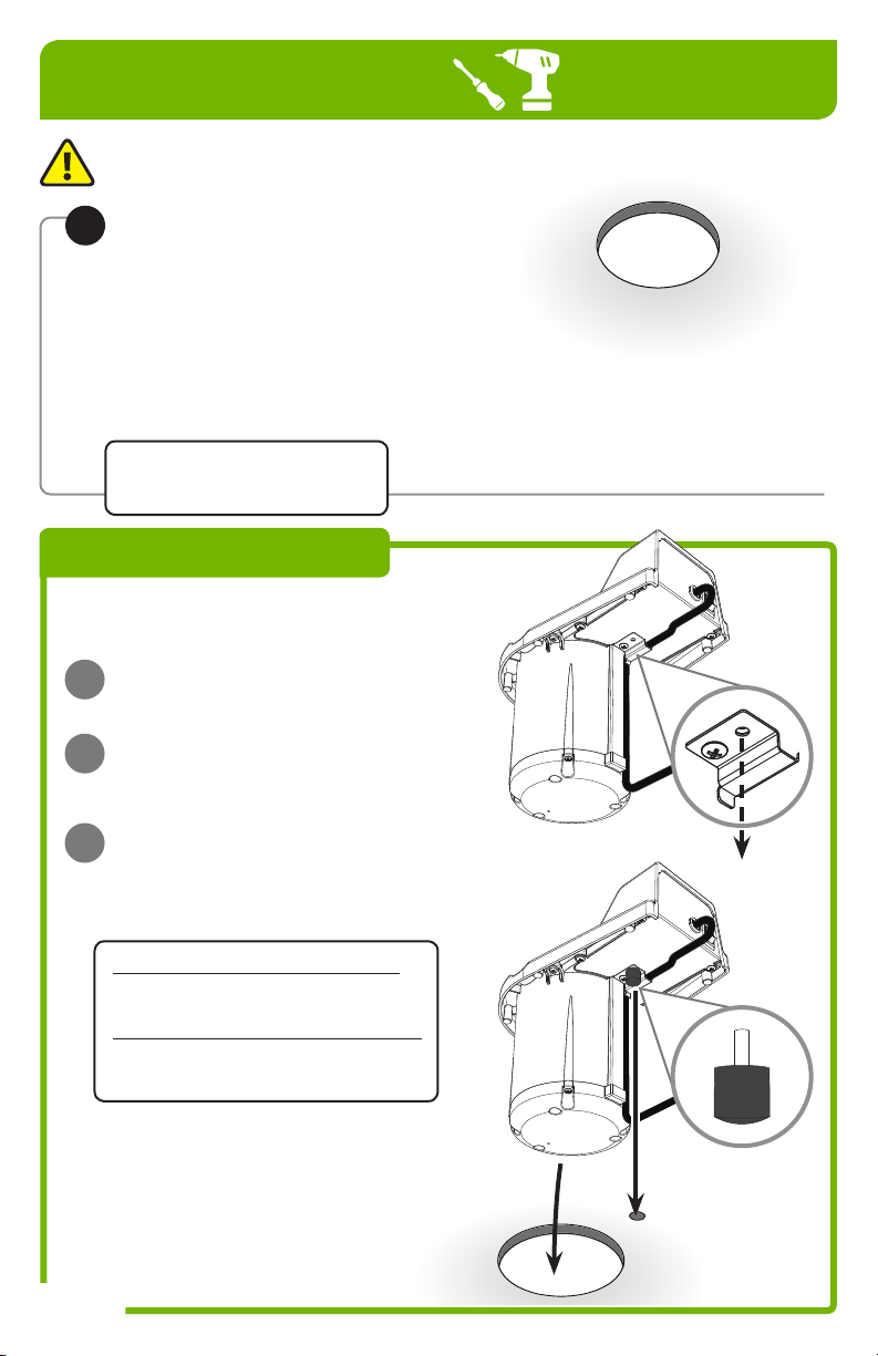
OPTIONAL
ADD ANTI-ROTATIONAL FOOT
to prevent unit pivoting within countertop hole.
REMOVE OUTER SCREW
A
from cord cover.
INSERT ANTI-ROTATIONAL
B
FOOT
in place of removed screw.
DRILL FOOT HOLE IN
C
COUNTERTOP
Refer to cutout template for details.
Drill 3/4" diameter hole in countertop.
5.75"—6.5" diameter countertop holes:
Locate foot hole center 3.75"
from large countertop hole center.
5.5" up to 5.75" diameter countertop hole:
Locate foot hole center 3.5"
from large countertop hole center.
NEW HOLE
Use appropriate personnel and tools to
cut a 6" diameter hole.
See below and refer to cutout template for
details on an additional optional
anti-rotational hole.
Page 2
UNIT & ANTI-ROTATIONAL
FOOT WILL FIT INTO
CORRESPONDING
COUNTERTOP HOLES.
Page 3
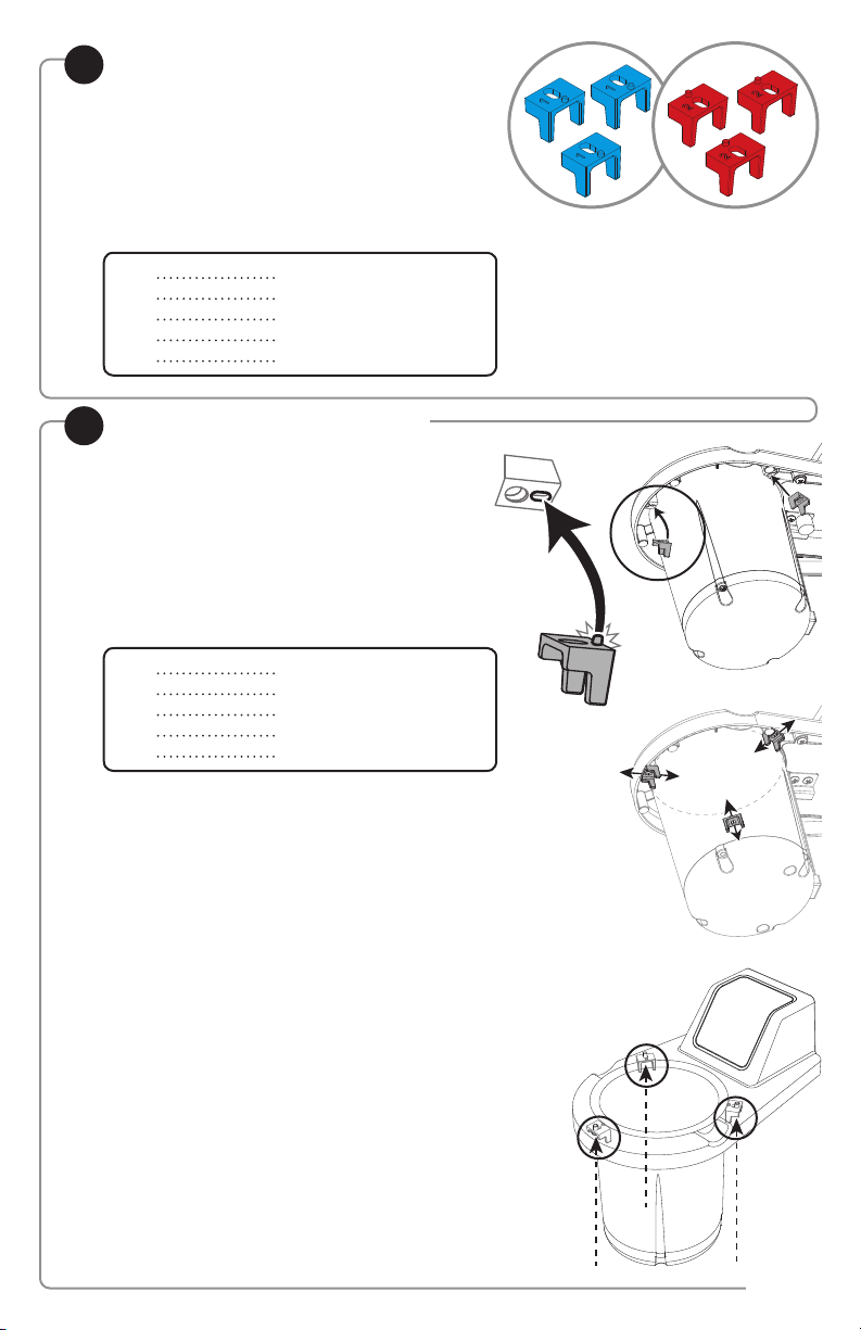
SELECT LOCATION BLOCK HARDWARE
2
to create proper fit within countertop hole.
Hole diameter determines which 3 location
blocks to use.
If size is between two listed dimensions,
refer to smaller diameter.
COUNTERTOP
HOLE DIAMETER
5.5"
5.75"
6"
6.25"
6.5"
ATTACH 3 LOCATION BLOCKS
3
to underside of rim.
Place each location block peg into slot in
underside of rim.
Slide location blocks either away from
or towards base.
Refer to chart below.
COUNTERTOP
HOLE DIAMETER
5.5"
5.75"
6"
6.25"
6.5"
LOCATION BLOCKS
No location blocks needed
BLUE, embossed with “1”
BLUE, embossed with “1”
RED, embossed with “2”
RED, embossed with “2”
LOCATION BLOCK FITTING
Remove all location blocks
BLUE, slide towards base
BLUE, slide away from base
RED, slide towards base
RED, slide away from base
Screw in each location block using 1 screw
and Phillips-head screwdriver.
Page 3
Page 4
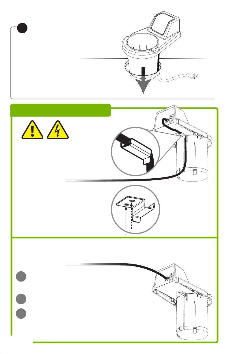
INSERT UNIT
4
and cord into countertop hole.
If outlet is above the countertop,
refer to CORD COVER instructions below.
CORD COVER
CAUTION-
PREVENT CORD DAMAGE
Secure cord within cord cover
when plug is used below counter.
USE CORD COVER WHEN
CORD IS PLUGGED IN BELOW
COUNTERTOP
Affix cord cover using 2 screws
and Phillips-head screwdriver.
A
B
C
Page 4
DO NOT USE CORD COVER
WHEN CORD IS PLUGGED IN
ABOVE COUNTERTOP
DETACH CORD COVER
Use Phillips-head screwdriver to remove
both screws.
RELEASE CORD
REATTACH CORD COVER
with both screws.
Secure onto unit in case of future need.
Page 5

INSERT WATER PAN
5
Fill 28 oz. of HOT water up to fill-line in pan.
Refer to water temperature charts below.
Insert pan of water into basin.
Pour water into pan only.
Never pour or spill water
directly into basin of unit.
NO
BE AWARE OF THE WATER TEMPERATURE
Help prevent bacteria growth. The FDA warns
that bacteria grow most rapidly in the range of
temperatures between 41°F—135°F. (5°C—57°C.)
YES
WATER HEATING TIMES
(When unit is not pre-heated)
INITIAL
TARGET TEMPERATURE
WATER
TEMP.
135°F 140°F 145°F
70°F 40 min. 45 min. 50 min.
110°F 25 min. 30 min. 40 min.
120°F 20 min. 20 min. 30 min.
130°F 15 min. 20 min. 25 min.
PLUG CORD INTO
6
POWER SOURCE
TURN UNIT ON
7
Press switch at back of unit.
PRESS RESET TO START
8
countdown cycle.
Timer is programmed
for 4 hour cycles.
WATER HEATING TIMES
(In pre-heated unit)
INITIAL
TARGET TEMPERATURE
WATER
TEMP.
135°F 140°F 145°F
70°F 30 min. 35 min. 40 min.
110°F 15 min. 20 min. 25 min.
120°F 5 min. 10 min. 15 min.
130°F 5 min. 5 min. 10 min.
Page 5
Page 6

WATER CHANGE-OUT
REMOVE & EMPTY PAN OF WATER
1
CAUTION- HOT
Unit, pan and water will be hot.
Take proper care while removing pan.
Carefully pour water down a drain.
REFILL & RETURN WATER PAN TO BASIN
2
Fill 28 oz. of new HOT water up to
fill-line in pan.
Insert pan of water into basin.
Never pour water
directly into basin of unit.
Pour water into pan only.
USING THE COUNTDOWN TIMER
Instructions for units with programmable timers.
PRESS RESET TO START COUNTDOWN CYCLE
1
Timer is factory programmed for 4 hour cycles.
When countdown timer ends:
Alarm will beep.
Display will indicate “END”
PRESS RESET TO STOP ALARM
2
To replace water BEFORE
3
4
Page 6
CHANGE OUT WATER
Complete “WATER CHANGE-OUT” steps listed above.
PRESS RESET BUTTON
to restart the countdown cycle.
countdown cycle ends,
follow steps 2—4.
Page 7

PROGRAMMING TIMER
Instructions for units with programmable timers.
SET COUNTDOWN CYCLE TIME
ENTER TIME PROGRAM MODE:
Simultaneously press and hold the
UP and RESET buttons for 10 seconds.
Red light indicates unit is in timer program mode.
SELECT DESIRED COUNTDOWN TIME:
Press the UP or DOWN buttons.
LOCK IN TIME SETTING AND EXIT
PROGRAM MODE:
Press and hold the RESET button for 3 seconds.
SET ALARM VOLUME
ENTER ALARM PROGRAM MODE:
Simultaneously press and hold the
DOWN and RESET buttons for 10 seconds.
10 SEC.
3 SEC.
10 SEC.
Beeping indicates unit is in alarm program mode.
SELECT ALARM VOLUME:
Press the UP or DOWN buttons. A beep
accompanies each level to indicate the volume
setting. Volume level is shown in display. Adjust
number to desired volume level.
LOCK IN VOLUME SETTING AND EXIT
PROGRAM MODE:
Press and hold the RESET button for 3 seconds.
UNIT TAKE-DOWN
CAUTION- HOT
Allow unit to cool first
or take proper care with hot surfaces.
PRESS SWITCH TO OFF
1
UNPLUG CORD
2
REMOVE PAN FROM BASIN
3
Pour water down a drain.
Clean pan. (See page 9.)
Dry pan fully with clean soft cloth.
VOLUME LEVELS
3- Highest volume
2- Average volume
1- Lowest volume
0- Silent (No audible alarm)
3 SEC.
Page 7
Page 8

SAFETY
WARNING-
ELECTRICAL SHOCK COULD OCCUR
This unit must be earthed or grounded.
This requires all three prongs (terminals)
on cord plug to be plugged into power source.
BE AWARE OF THE WATER TEMPERATURE
Help prevent bacteria growth. The FDA warns
that bacteria grow most rapidly in the range of
temperatures between 41°F—135°F. (5°C—57°C.)
NSF International listed.
This unit is not to be used for serving food.
Page 8
Page 9

CLEANING
WARNING-
ELECTRICAL SHOCK COULD OCCUR
YES!
Use dishwashing
soap and hot water
Pan is dishwasher safe.
• Electrical components of unit could
be damaged from water exposure or
any liquid.
• Never immerse unit into water or any liquid.
• Never use any water jet or pressure
sprayer on unit.
• Ensure unit is “OFF” and unplugged.
CAUTION- HOT
Allow unit to cool before cleaning.
CLEAN THE PAN
CLEAN
1
Wash water pan
with soap and hot water.
RINSE
2
fully with clear water.
SANITIZE
3
all parts according to local sanitization
requirements. All parts in contact with
food must be sanitized.
DRY
4
pan fully with a clean soft cloth.
CLEAN EXTERNAL
SURFACES
• Wipe daily with a clean damp cloth.
• Dry with a clean soft cloth.
• Glass and surface cleaners approved
for use in food contact areas may be used.
CARE OF STAINLESS STEEL
The water pan is constructed
of stainless steel.
If you notice corrosion beginning on any
stainless steel surface, you may need to change
the cleansing agent, sanitizing agent, or the
cleaning procedures you are using.
• A mildly abrasive nylon or brass brush may
be used to remove any stubborn deposits on
interior surfaces of unit.
• Fully rinsing and drying all parts can help
prevent corrosion. Elements and minerals in
tap water can accumulate on stainless steel
parts and create corrosion.
• Do not use abrasive, caustic or ammonia
based cleansers.
• Do not use products containing acids,
alkalines, chlorine, or salt. These agents can
corrode stainless steel.
• Do not use metal scrapers or cleaning pads
that could scratch surfaces.
Page 9
Page 10

WIRING DIAGRAM
87760
120V USA
1 2 3 476
A
B
C
8 5
Cord Assembly
1
120V
Black
A
White
B
Green
C
2 5
Bushing/Strain Relief
Rocker Switch
3 6
Wire Assembly, 18GA, Black, 4"
4 7
8
128C Pepi, Thermal Assembly, Cut-out
Wire Nut
100W Silicone Element
Wire Assembly, 18GA, Green, 14"
87770
120V USA
Programmable Timer
Cord Assembly
1
120V
Black
A
White
B
Green
C
2
Bushing/Strain Relief
Rocker Switch
3
Wire Assembly, 18GA, Black, 4"
4
128C Pepi, Thermal Assembly, Cut-out
5
Wire Nut
6
100W Silicone Element
7
Wire Assembly, 18GA, Green, 14"
8
Transformer Assembly
9
Timer Board
10
Page 10
1 2
A
B
C
RED
YELLOW
+
9
BLACK
WHITE
-
3 4 6
10
5
8
7
Page 11

TROUBLESHOOTING
UNIT DOES NOT HEAT? WATER NOT REACHING 140° F?
• Ensure cord is securely plugged in.
• Ensure power is available from source.
• Ensure unit is on.
UNIT OVERHEATING?
• Ensure water has not spilled or leaked
from pan into the basin.
CAUTION:
WATER IN BASIN MAY STEAM & BURN.
• Allow unit to cool. Pour out any water and
dry basin.
• Make sure to use HOT water in pan.
Refer to temperature charts on page 5.
• Damaged pan may not heat properly.
Inspect and replace pan if needed.
SERVER PRODUCTS
LIMITED WARRANTY
Server Products equipment is backed by a
two-year limited warranty against defects in
materials and workmanship.
For complete warranty information go to:
www.Server-Products.com
GENERAL SERVICE,
REPAIR OR RETURNS
Before sending any item to Server Products
for service, repair, or return, contact Server
Products customer service to request a Return
Authorization Number. Merchandise must be
sent to Server Products with this number. Service
is extremely prompt. Typically, units are repaired
and ship out within 48 hours of receipt.
Merchandise being returned for credit must be in
new and unused condition and not more than 90
days old and will be subject to a 20% restocking
charge. Electrical parts (thermostats, heating
elements, etc.) are not returnable.
Servicing Cord: Specific tools are required for
safe and proper power supply cord removal
and installation. If cord must be replaced, only
a representative of the OEM (original equipment
manufacturer) or a qualified technician may
replace cord. Cord must meet code designation
H05 RN-F requirements.
Page 11
Page 12

CONSERVEWELL™ DROP-IN
MODEL: CW-DI
PAN
87771
LOCATOR BLOCK HARDWARE
Two Sets Supplied:
#1 BLUE LOCATOR BLOCKS (QTY 3) 87785
#2 RED LOCATOR BLOCKS (QTY 3) 87786
CORD COVER
87795
ANTI-ROTATIONAL FOOT
81058
HELP or ORDERING REPLACEMENT PARTS
Server Products Inc.
3601 Pleasant Hill Road
Richfield, WI 53076 USA
262.628.5600 | 800.558.8722
SPSALES@SERVER-PRODUCTS.COM
Page 12
Please be prepared with your Series Number and
Description located on the back of the unit.
Individual Part Numbers listed above.
Manual #01925-RevA 090215
 Loading...