

Server Products 250 Service Manual
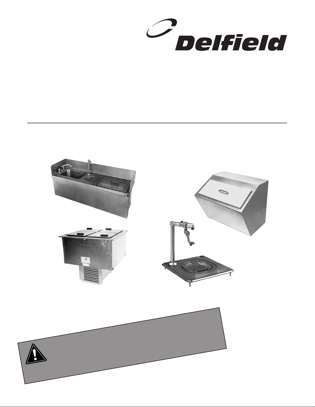
200 & 300 SERIES
CAUTION
Service and Installation Manual
Please read this manual completely before attempting to install or operate this equipment!
Notify carrier of damage! Inspect all components immediately. See page 2.
Drop In and Undercounter Products
IMPORTANT INFORMATION
READ BEFORE USE
PLEASE SAVE THESE INSTRUCTIONS!
Effective APRIL 2003
200 and 300 Series Service and Installation Manual
200 and 300 Series Service and Installation Manual
3
For customer service, call (800) 733-8829, (800) 773-8821, Fax (989) 773-3210, www.deleld.com
CONTENTS
RECEIVING & INSPECTING EQUIPMENT ................................. 2
SPECIFICATIONS........................................................................2
INSTALLATION .......................................................................... 3
SERIAL NUMBER INFORMATION
The serial number on all Model 225 and 227 units is located
on the tag affixed next to the temperature control, inside the
compressor stand at the bottom of the unit.
OPERATION................................................................................4
MAINTENANCE .......................................................................... 4
WIRING DIAGRAM .................................................................... 8
STANDARD LABOR GUIDELINES.............................................. 9
REPLACEMENT PARTS LIST..................................................5-8
STANDARD WARRANTY.....................................................10-11
PARTS DEPOTS ........................................................BACK PAGE
Always have the serial number of your unit available when calling for parts or service.
©2003 The Delfield Company. All rights reserved. Reproduction without
written permission is prohibited. “Delfield” is a registered trademarks of
The Delfield Company.
RECEIVING AND INSPECTING THE EQUIPMENT
Even though most equipment is shipped packaged, care
should be taken during unloading so the equipment is not
damaged while being moved into the building.
1. Visually inspect the exterior of the package and skid or
container. Any damage should be noted and reported to
the delivering carrier immediately.
2. If damaged, open and inspect the contents with the
carrier.
3. In the event that the exterior is not damaged, yet upon
opening, there is concealed damage to the equipment
notify the carrier. Notification should be made verbally
as well as in written form.
4. Request an inspection by the shipping company of the
damaged equipment. This should be done within 10
days from receipt of the equipment.
5. Visually inspect the refrigeration package. Be sure lines
are secure and base is still intact.
6. Freight carriers can supply the necessary damage forms
upon request.
7. Retain all crating material until an inspection has been
made or waived.
SPECIFICATIONS
MODEL OVERALL CUTOUT CABINET DESIGN SYSTEM
NUMBER L D H SIZE CAPACITY H.P. AMP LOAD BTU CAP. BTU
DROP-IN ICE CREAM FREEZERS
N225
16.56” 27.87” 26.75” 26.37” x 15.37” 6 gal. 1/4 5.0 292 569
N227
30” 27.87” 26.75” 26.37” x 28.56” 12 gal. 1/4 5.0 473 661
DROP-IN ICE CREAM FREEZERS WITH LEXAN® LID
225L
16.56” 27.87” 26.75” 26.37” x 15.37” 6 gal. 1/4 5.0 292 569
227L
30” 27.87” 26.75” 26.37” x 28.56” 12 gal. 1/4 5.0 473 661
MODEL OVERALL CUTOUT ICE
NUMBER DESCRIPTION L D H SIZE CAPACITY
DROP-IN WATER STATIONS AND ICE STORAGE
203
ice chest 20.25” 20.25” 23.25” 19.25” x 19.25” 90 lbs.
204
water and ice station 24” 21” 23.5” 21” x 17.75” 45 lbs.
240
ice chest with cover 21” 17.5” 17” — 75 lbs.
248
water and ice station 31” 15” 22.5” 28” x 12.5” 45 lbs.
305
ice chest with cover 21.25” 15.25” 13” 17.75” x 13.25” 45 lbs.
307
glass filler 12” 12” 9.5” — —
UNDERCOUNTER SINKS, WATER STATIONS AND ICE STORAGE
242
UC sink & faucet 18” 13.5” 12.75” 17” x 12.5” —
250
UC sink, ice chest 46” 14.12” 22.75” 45” x 13” 45 lbs.
and water station
2
For customer service, call (800) 733-8829, (800) 773-8821, Fax (989) 773-3210, www.deleld.com
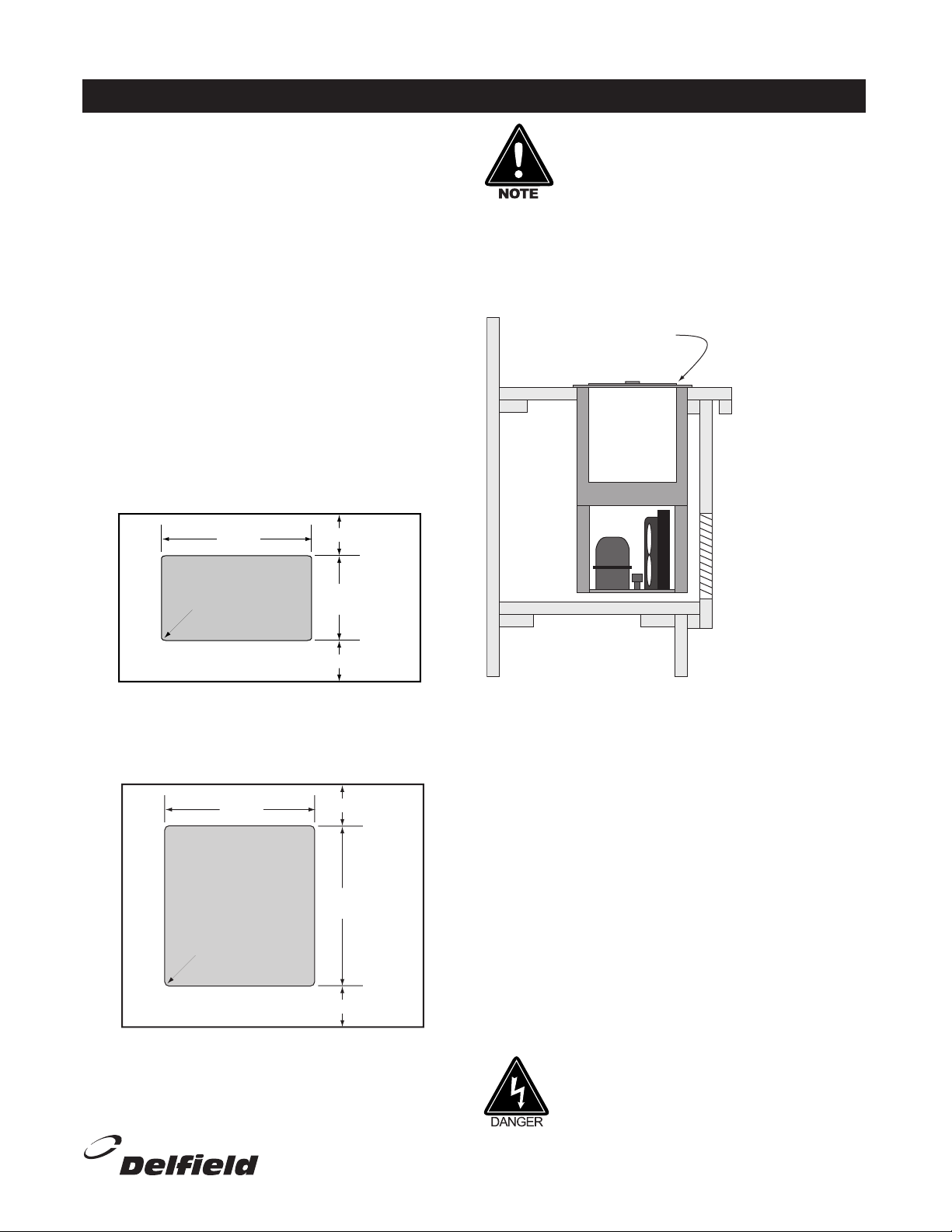
INSTALLATION
225 or 227 DROP-IN
TYPICAL
COUNTER
CABINET
LOUVER
13.00" x 24.37"
33.0cm x 61.9cm
LOUVER CUTOUT SIZE
11.50" x 23.00"
29.2cm x 58.4cm
(typical installation)
NOTE: A second cutout
(without louver) must
also be made to allow
proper air flow.
26.37"
67.0cm
28.56"
72.5cm
CUTOUT
.75"/1.9cm radius
1.00"/2.5cm (min.)
1.00"/2.5cm (min.)
COUNTERTOP
26.37"
67.0cm
15.37"
39.0cm
CUTOUT
.75"/1.9cm
radius
1.00"/2.5cm (min.)
1.00"/2.5cm (min.)
COUNTERTOP
200 and 300 Series Service and Installation Manual
Location
The refrigeration system has been factory tested
and should require no further adjustment during
installation.
For the most efficient refrigeration, be sure to provide
good air circulation inside and out.
Outside Cabinet: Be sure that the unit has access
to ample air. Avoid hot corners and locations near
stoves and ovens.
Counter Cutouts
For installation provide a cutout in the counter as
shown (see illustration 1 or 2). The counter must be
sturdy enough to hold the combined weight up to 300
lbs. of the drop-in and the product stored inside.
The louver provided must be installed
in front of the condensing unit’s finned
coil (see illustration 3). A second
cutout must be made at the rear or
end of the equipment to allow air flow
through the unit. No louver is provided
for the second cutout. Any restriction
to the proper air flow, total or partial,
will void the compressor warranty.
Illustration 1. Model 225 cutout dimensions
Illustration 2. Model 227 cutout dimensions
For customer service, call (800) 733-8829, (800) 773-8821, Fax (989) 773-3210, www.deleld.com
Illustration 3. Models 225 & 227 louver installation
Electrical Connection
Refer to the amperage data on page 2, the serial tag,
your local code or the National Electrical Code to be
sure the unit is connected to the proper power source.
A protected circuit of the correct voltage and amperage
must be run for connection of the line cord.
If the unit does not operate after it is plugged in, check
the thermostat to see if it was inadvertently turned
OFF during installation.
The unit must be disconnected from
the power source whenever performing
service or maintenance functions.
3
200 and 300 Series Service and Installation Manual
200 and 300 Series Service and Installation Manual
5
For customer service, call (800) 733-8829, (800) 773-8821, Fax (989) 773-3210, www.deleld.com
OPERATION MODELS 225 AND 227
After installation, the unit will begin operating simply
by plugging it into the proper outlet. If the unit does
not operate after being plugged in, check to see if the
thermostat is in the OFF position.
MAINTENANCE MODELS 225 AND 227
In order to maintain proper refrigeration performance,
the condenser fins must be cleaned of dust, dirt, and
grease every three months. If conditions are such
that the condenser is totally blocked in three months,
the frequency of cleaning should be increased.
Clean the condenser with a vacuum cleaner or stiff
brush. If extremely dirty, a commercially available
condenser cleaner may be required.
Defrosting must be done manually after 3/8” of ice
accumulation.
The models 225 and 227 are designed to
hold ice cream or other frozen products at a
temperature range of 5°F to -5°F (-15°C to 21°C). The thermostat is located in the machine
compartment.
The lid should be cleaned regularly with a soft
cloth or sponge and solution of soap and water to
maintain their ability to seal properly.
MAINTENANCE - MODELS 203, 204, 240, 242, 248, 250, 305 & 307
The interior and exterior of these models may be
cleaned using soap and warm water. If this is not
sufcient, try ammonia and water or a non-abrasive
cleaner. Be sure to rinse thoroughly with clean water
after using ammonia or a cleaner. When cleaning the
exterior, always rub with the “grain” of the stainless
steel to avoid marring the nish.
Do not use an abrasive cleaner. Abrasive
cleaners will scratch the stainless steel
and plastic.
4
For customer service, call (800) 733-8829, (800) 773-8821, Fax (989) 773-3210, www.deleld.com
 Loading...