

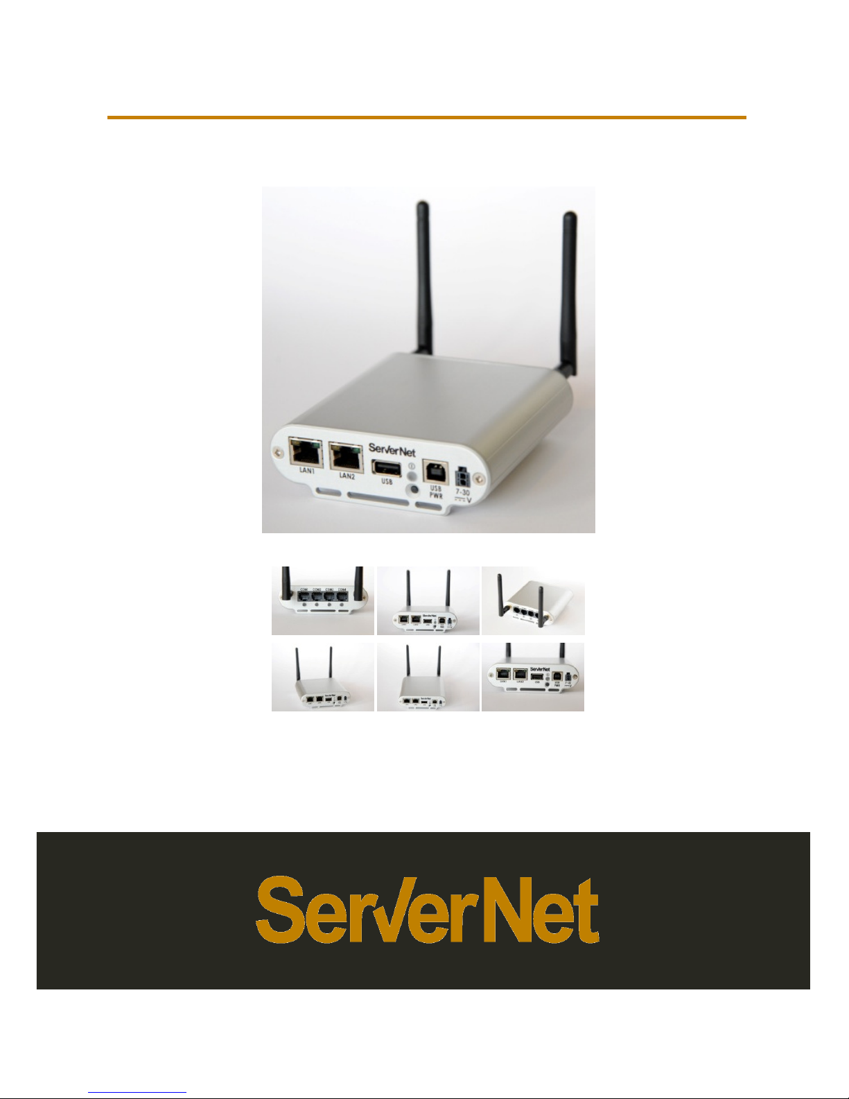
LS24I/M
Device User’s Guide

Apr, 2016 LS24I/M User guide
Copyright ServerNet S.r.l. 2015-2016, All Rights Reserved
Identifier:
LS24
Document Version: 04
.04
Effective Date: Apr
,
Document Catalog Number:
LS24
Author:
Michele De Monte
Technical review:
Vedran Jukic
Approval:
Angelo Pingue
LS24I/M
2
I/M
06,2016
I-M_HW_0400

LS24I/M
3 LS24I/M User guide
Copyright ServerNet S.r.l. 2015-2016, All Rights Reserved
Table of Contents
Table of Contents ................................................................
................................
Revision History ................................................................
................................
Preface................................................................................................
................................
Package contents ................................................................
................................
Device accessories and custom options ................................
................................
1. General elements ................................................................
................................
1.1.
Forwards ................................................................
................................
1.2.
Definitions ................................................................
................................
1.3.
Intended Use ................................................................
................................
1.4.
Warnings, Precautions and Notes ................................
................................
1.4.1. Warnings ................................................................
................................
1.4.2. Precautions ................................................................
................................
1.4.3. Notes ................................................................................................
................................
1.5.
Labelling ................................................................
................................
1.6.
Controls and Indicators ................................
................................
1.6.1. LED Indicators ................................................................
................................
1.6.2. Audio indicators ................................................................
................................
1.6.3. Symbols ................................................................
................................
1.7.
ServerNet’s Responsibilities ................................
................................
2. LS24I/M features
(*)
................................................................
................................
2.1.
LS24I/M main features
(*)
................................
................................
2.2.
LS24I/M internal accessories
(*)
................................
................................
3. LS24I/M Overview ................................................................
................................
3.1.
LS24I front connectors ................................
................................
3.2.
LS24M front connectors ................................
................................
3.3.
LS24I/M rear connectors ................................
................................
3.4.
LS24I/M front rear top view................................
................................
4. LS24I/M Mounting Options................................
................................
4.1.
Bracket mounting option ................................
................................
4.2.
Velcro Mounting option ................................
................................
5. Important preliminary operations ................................
................................
Apr, 2016
............... 3
.................. 5
.... 6
............... 7
..... 8
...... 9
............................ 9
........................ 10
.................. 10
........... 11
.......................... 11
...................... 14
. 14
........................... 16
.............................. 21
................ 21
............. 22
............................ 23
...................... 24
25
........................... 25
................ 26
.. 27
............................... 27
.............................. 27
............................ 28
...................... 28
.................. 29
............................ 29
............................... 32
.... 33

Apr, 2016 LS24I/M User guide
Copyright ServerNet S.r.l. 2015-2016, All Rights Reserved
6. Starting with LS24I/M ................................
................................
6.1.
Using the ON/OFF button ................................
................................
6.2.
Using USB type B power port ................................
................................
6.3.
Using 7-30V power connector (only for LS24I)
................................
6.4.
Battery charging ................................................................
................................
6.5.
Turning on LS24M: OS loading and status LED options
7. Using LS24I/M ................................................................
................................
8. Accessing the LS24I/M ................................
................................
9. LS24I/M OS use and configuration ................................
................................
10.
System recovery ................................................................
................................
11.
Battery removal ................................................................
................................
12.
LS24I/M storage ................................................................
................................
13.
Disposal of the Product ................................
................................
14.
User manual download ................................
................................
LS24I/M
4
........................... 33
........................... 35
................... 35
................. 36
............ 37
.............................. 38
......... 39
......................... 39
.. 39
39
.. 39
. 40
.................... 40
.................... 40

LS24I/M
5 LS24I/M User guide
Copyright ServerNet S.r.l. 2015-2016, All Rights Reserved
Revision History
Version
Date
Changes
01.00
Jun, 12, 2015
LS24M manual
02.00
Jul, 29, 2015
LS24I/M updated version with UL requirements
03.00
Aug, 31,2015
LS24I/M including O
.S. inside of the evaluation
for UL certification
04.00
Sept,17,2015
Updates after Testhaus performing tests
04.01
Oct,06,2015
Update with UL request for linking device with
specific power adapter to allow “
Classified
classification
04.02
Nov,02,2015
Update with UL request for warnings for IT
Network devices
04.03
Nov,18,2015
User manual download link added, minor
language changes
04.04
Apr,06,2016
Improved
in Chapters 5, 6 and 6.4
information
for device switch on when
device is inactive for a long time and
internal battery is completely discharged
Apr, 2016
Author
De Monte
De Monte
De Monte
De Monte
”
De Monte
-
De Monte
De Monte
De Monte

Apr, 2016 LS24I/M User guide
Copyright ServerNet S.r.l. 2015-2016, All Rights Reserved
Preface
Thank you for choosing our LS24I or LS24M
version
network controlled implementations.
Setup operations was designed
to allow you to start using your device in
the shortest time possible.
Nevertheless, it’s fundamental for a responsible
and reliable
device to read carefully the Device User’s Guide
before starting and using
device in both versions
and before reading Device Operating System user’s
guide.
This manual is intended to provide information for the proper operation of
both LS24I and LS24M version.
If no restriction is reported, it refers to both device versions; otherwise
refers to the corresponding mentioned device version.
IMPORTANT:
Medical grade rou
ting and computing device models LS24I and LS24M are:
MEDICAL -
GENERAL MEDICAL EQUIPMENT AS TO ELECTRICAL SHOCK,
FIRE AND MECHANICAL HAZARDS ONLY IN ACCORDANCE WITH:
ANSI/AAMI ES60601-1 (2005) + AMD 1 (2012),
CAN/CSA-C22.2 No. 60601-1 (2014)
E477923
IMPORTANT:
Before starting the configuration of
your LS24I/M be sure that the battery
is fully charged.
LS24I/M
6
device for your
use of this
it

LS24I/M
7 LS24I/M User guide
Copyright ServerNet S.r.l. 2015-2016, All Rights Reserved
Package contents
The package includes:
• 1 x LS24I/M device assembly
(*)
• 2 x rubber antennas
(**)
• 1 x 1m UL approved USB A to B cable for device
power
• 1 x M3 inox nut for case ground locking
• 1 x 3 mm inox star washer for case ground locking
• 1 x wall mount bracket
• 1 x user’s guide link card for online user manual
download
Some other accessories can be assembled inside of the LS24I/M
part of the package to complete its wide connectivity set.
Refer to the product number P/N for more details.
(*)
Different product numbers depending on device case features,
communication module
storage microSD inside
(**)
Different part numbers depending on wireless communication module
inside (
BT,…)
Apr, 2016
supply 5V-1A
and/or be
and
WiFi, 3G/UMTS,

Apr, 2016 LS24I/M User guide
Copyright ServerNet S.r.l. 2015-2016, All Rights Reserved
Device accessories and custom options
LS24I and LS24M basic version includes:
• USB, COM and LAN connectivity
• 1750 mAh medical grade internal battery
• silver anodized case and panels
• standard front panel silkscreen.
• 1 x wall mount bracket
• 1 x M3 inox nut for case ground locking
• 1 x 3 mm inox star washer
LS24I and LS24M can be customized
with the following internal
options and accessories:
Internal options:
• WiFi connectivity FCC certified module
• 3G/UMTS connectivity FCC certified module
with SIM card slot
Module)
• BT4 connectivity FCC certified module
• MicroSD card with different commercial capacity
alternatives
32, 64,… GB) and speed class (4, 10,…)
Extenal options and accessories:
• 2 x 2.4GHz WiFi antennas
(for WiFi connectivity)
• 2 x pentaband 3G/UMTS antennas
(for 3G/UMTS connectivity)
• 1m UL approved
USB A to B cable for device power supply 5V
• Friwo GPP USB 5V-
1500 mA USB power supply UL medical grade
certified (part number: 1895382)
(optional to be ordered separately)
• Friwo FW7721M (GPP USB)
primary adapter for EURO (part number:
1827417)
(optional to be ordered separately)
•
Friwo GPP USB primary adapter for US/JPN (part number: 1827422)
(optional to be ordered separately)
• >1m UL approved USB A to B cable
for device power supply 5V
(optional to be ordered separately)
• Custom case color
(front and rear panel anodized color)
separately)
• Custom front panel silkscreen
(optional to be ordered separately)
• COM, LAN, USB A, USB B, 7-30
V connector protection caps
ordered separately)
LS24I/M
8
/external
(replaces WiFi
(4, 8, 16,
-1A
-1A
(optional to be ordered
(optional to be
LS24I/M
9 LS24I/M User guide
Copyright ServerNet S.r.l. 2015-2016, All Rights Reserved
1. General elements
1.1. Forwards
This manual is intended to provide information for the proper operation of
both the LS24I and the LS24M.
DO NOT OPERATE THIS SYSTEM BEFORE READING CAREFULLY THESE
INSTRUCTIONS.
LS24I and LS24M are intended to be
setup, installed, serviced and
maintained only by qualified personnel authorized
by ServerNet after
specific training sessions.
DO NOT OPERATE THESE ACTIVITIES
IF YOU DO NOT HAVE ATTENDED TO
THE REQUIRED QUALIFYING TRAINING SESSIONS.
LS24I and LS24M does not contain any user-serviceabl
e parts.
DO NOT REMOVE DEVICE COVER.
Refer servicing to qualified and ServerNet authorized personnel only.
Final user personnel must refer to third part
configuration
to know how to operate with the device
during the specific implemented
running mode.
For additional information or assistance
about the device and its operating
system please contact:
ServerNet S.r.l.
Località Padriciano, 99
34149 Trieste (Italy)
http://www.servernet.it
e-mail: support@servernet.it
Apr, 2016
documentation

Apr, 2016 LS24I/M User guide
Copyright ServerNet S.r.l. 2015-2016, All Rights Reserved
1.2. Definitions
ServerNet S.r.l.
: in the document may be referred to herein also as
ServerNet
LS24I/M: indicates both device models.
Warning
: is provided if there is a reasonable evidence of an association of
a serious personal hazard with device use.
Precaution
: is provided when any special care is to be exercised by the
practitioner to avoid causing damage to this device or other property.
Note
: can be provided when extra general information is applicable.
Hardware: indicates LS24I/M.
Operating system or O.S.: indicates the basic
unchangeable
installed into each hardware with the basic functions of loading
Configurations including
set of parameters, data and instructions
to implement specific functionalities.
Configuration: any third part
set of device parameters
loaded on the hardware to allow its fine controlling,
management,
query, data collection and data transfer from/to other electronic devices
and systems.
7-30V DC: refers to a power source with 7-30V
DC with power of 5W or
higher.
Friwo USB power adapter: referred also as
Friwo USB power adapter
part number 1895382
or Friwo GPP USB or Friwo FW7721M
1.3. Intended Use
The LS24I and LS24M are general routing and
computing device
for use in data query, data collection and data
transfer from/to
electronic devices.
LS24I/M can operate from bedside and point of care,
medical devices and
clinical information management systems either directly or throug
networks with independent bedside devices.
LS24I/M
10
software
/deleting
required
and data to be
data
s intended
other
h

LS24I/M
11 LS24I/M User guide
Copyright ServerNet S.r.l. 2015-2016, All Rights Reserved
LS24I/M support routing a computing int
erface with devices connected to
their connectors, but do not provide by themselves
data query, collection
and transfer. To do this they require
specific Configurations to
Third part specific Configurations are required,
must be loaded
responsible for services such as
device recognition, data query, collection
interpretation, management, transmission and reception.
LS24I/M includes a medical grade
battery to support device power during
its use. Nevertheless, its intended use is NOT to work as a battery powered
device.
Internal battery is intended for temporary backup of
external
supporting LS24I/M normal operations
in case of temporar
failure or temporary power needs exceeding 500 mA
(if power source is
limited to this current level) or 1000 mA.
By design, the LS24I/M is maintaining the battery fully
cannot be changed by any option including powering of
the device.
consider the orange LED
on the front panel to see if device is in charge or
not.
LS24I/M is also designed to wake up when USB
power connector
DC power connector (only for LS24I) is plugged to a
power source.
battery was completely discharged, a few seconds to a few minutes
may occur to catch a minimum level
battery operation charge.
LS24I/M is classified as “Classified
” device by UL when used together with
Friwo GPP USB 5V-1500 mA USB power
supply UL medical grade and its
primary adapters.
1.4. Warnings, Precautions and Notes
Please read and adhere to the following list of warnings, precautions,
and notes.
1.4.1. Warnings
Internal Electrical Shock Hazard – the LS24I/M
does not contain any user
serv
iceable parts. Do not remove device cover. Refer servicing to
and ServerNet authorized personnel only.
Apr, 2016
be loaded.
and are
,
power source
y power source
charged and this
Please,
or 7-30V
If the
delay
-
qualified

Apr, 2016 LS24I/M User guide
Copyright ServerNet S.r.l. 2015-2016, All Rights Reserved
Do not use in the presence of flammable gases.
IMPORTANT.
Internal Battery.
LS24I/M has an internal medical grade lithium battery.
Do not remove or replace the lithium battery.
Refer
replacement to
qualified and ServerNet authorized personnel
prevent injury or burns, do not disassemble, crush, short circui
or dispose of in fire the internal battery.
Class1 medical device.
The LS24I/M is a Class 1 medical equipment: to
avoid the risk of electric shock, this equipment must only be connected to
a supply mains with protective earth.
Power source. The LS24I/M is a medical device
designed to operate in
medical environment and hospitals: it has to be
connected to a
grade power source (USB or 7-30V DC) and to
medical grade devices
compliant with UL 60601-1 3.1 Edition requirements.
Medical grade power source is not directly
supplied by ServerNet
there is an option listed as optional accessory.
The USB power adapter whose part number
is listed as accessory
USB power adapter: 1895382),
is the one used during
process. LS24I/M is considered by UL as “Classified
” device
60601-1 3.1 Edition only if used together
with this power adapter
Refer to Friwo USB
power adapter documentation for specific needs about
its functions, use parameters,
life service and maintenance
LS24I, when powered using the 7-30V,
may not be used on the patient
area unless you’re using a 7-30V
medical grade power supply compliant
with UL 60601-1 3.1 Edition requirements.
If supplied with the 7-30V power source,
LS24I is not considered by UL a
“Classified” device.
Take care to evaluate in advance your application
in accordance with
60601-
1 3.1 Edition norm the LS24I/M if you want to power supply it
differently from what previously described.
Medical device connections.
When connecting serial/LAN ports to
medical devices, be sure you’re operating the LS24I/M in accordance with
60601-1 3.1 Edition
IT Network connection. LS24I/M is an IT-
Network device
to an IT-network that includes other equipment
could result in previously
unidentified risks to Patients, Operators or third parties
due to an inability
LS24I/M
12
lithium battery
only. To
t, overheat
medical
even if
(Friwo
UL certification
compliant with
.
.
: connecting it

LS24I/M
13 LS24I/M User guide
Copyright ServerNet S.r.l. 2015-2016, All Rights Reserved
for LS24I/M device to communicate data
. The Responsible Organization
should identify, analyze, evaluate, and control these risks
has not been specifical
ly tested and approved on the customer IT
Subsequent changes to the IT-
network could introduce new risks and
require additional analysis; changes in the IT-
network include:
• changes in the IT-network configuration;
• connection of additional items to the IT-network;
• disconnecting items from the IT-network;
• update of equipment connected to the IT-network;
• upgrade of equipment connected to the IT-network.
Electromagnetic compatibility. LS24I/M devices
without a radio module
installed conform to the requirements of EN 60601-1-
2:2007 + AC:2010,
clause 6. In particular:
Clause(s) Test
Emissions
6.1.1.2 Conducted disturbance at mains terminals
150 kHz – 30 MHz
6.1.1.2 Radiated disturbance 30 MHz – 1 GHz
Immunity
6.2.2
Electrostatic discharge (ESD)
6.2.3
Radiated RF electromagnetic fields
6.2.4
Electrical fast transients and bursts
6.2.5
Surges
6.2.6
Conducted disturbances, induced by RF fields
The LS24I/M emissions
are not likely to cause any interference in nearby
electronic equipment. The LS24I/M is
a “EN55022 Class b” device
for use in all establishments, including domestic establishments and those
directly connected to the public low-
voltage power supply network that
supplies buildings used for domestic purposes.
Apr, 2016
since the product
-network.
Basic standard
EN 55022
EN 55022
EN 61000-4-2
EN 61000-4-3
EN 61000-4-4
EN 61000-4-5
EN 61000-4-6
suitable

Apr, 2016 LS24I/M User guide
Copyright ServerNet S.r.l. 2015-2016, All Rights Reserved
1.4.2. Precautions
Observe all warning lights on the LS24I/M
(see following chapter
Do not immerse the LS24I/M
in solvents or cleaners. Clean the LS24
surface with a soft cloth dampened with a hospital grade cleaning solution.
If in use in medical environment and hospitals, the LS24
connected to biomedical devices and power sources
which meet UL 60601
1 3.1 Edition requirements.
Since LS24I/M is designed to load and
support third part
ServerNet can not be responsible for eventual
damages related to:
• third part Configuration
wanted or unwanted behaviours such as
incorrect parameter definition, loading, design issues
,…
• correct running of any third part loaded C
onfiguration
o Configuration parameter updates and
upgrades
o source/destination bio
medical device firmware changes and
revisions.
Please, refer to third part Configuration
documentation from the
Configuration
producer to know how to operate with the device and with
the Configuration loaded on device running mode.
1.4.3. Notes
Both models LS24M and LS24I comply
with Part 15 of the FCC Rules.
The LS24I/M can be
equipped with a WiFi radio module for
connection to an existing wireless LAN.
Operation is subject to the following two conditions:
(1) this device may not cause harmful interference, and
(2) this device must accept any interference received, including that which
may cause undesired operation.
For WiFi
module certification see related FCC ID on the device
label.
If the LS24I/M is equipped with a WiFi radio module
, according to EMC
recommendations and if it is not differently stated by your
Organization
, it is recommended to place the device antenna no less than
LS24I/M
14
1.6.1).
I/M
I/M shall only be
-
Configurations,
in relation with:
,
wireless
certification
Responsible

LS24I/M
15 LS24I/M User guide
Copyright ServerNet S.r.l. 2015-2016, All Rights Reserved
0.5 meters from other medical devices in order to avoid electromagnetic
interferences.
The LS24I/M can be also equipped with a radio module
(replac
module) for wireless connection to a WAN using
3G/UMTS
For radio module certification see related FCC ID
written
device certification label.
When using the WiFi or the 3G/UMTS feature of the LS24I/M, you have to
follow your organization's recommendations on placement of wireless
devices. Do not use
the LS24I/M with 3G/UMTS radio module
equipment without requesting permission from your Responsible
Organization.
Apr, 2016
ing the WiFi
mobile network.
on the related
near medical
Apr, 2016 LS24I/M User guide
Copyright ServerNet S.r.l. 2015-2016, All Rights Reserved
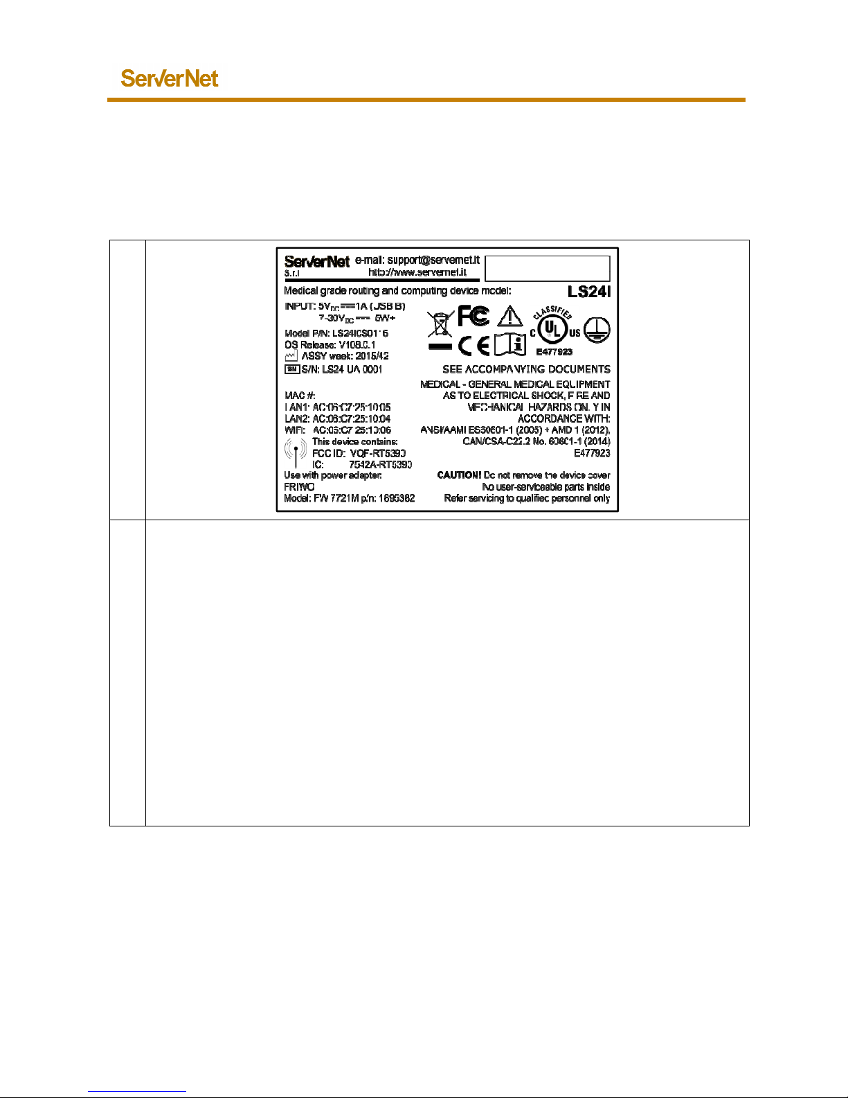
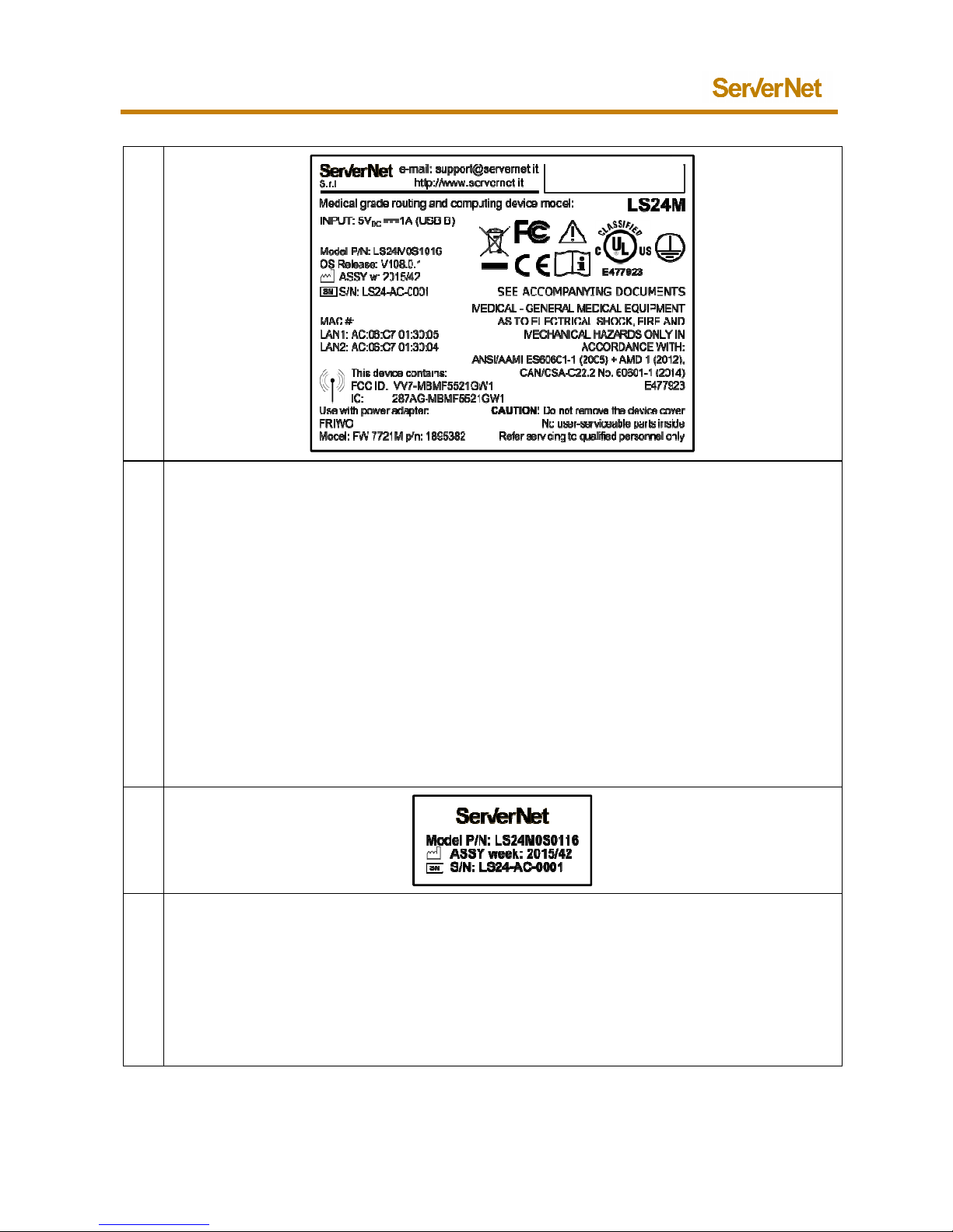
1.5. Labelling
In the following table there are some examples of
different
labels (L) with the corresponding description (D).
L
D
LS24I Wi
Fi
backside certification label
.
Dimensions: 65x50 mm.
Material: 3M 76751 silver.
Includes:
• web site and e-mail address for HW customer support
•
input supply voltage for 5V 1A USB B power supply and for 7
supply; for 7-30V DC 5W+ means power
supply with 5W or higher
• Model P/N: indicates device product model
related to customer
features
• OS Release: indicates installed release for the OS
• ASSY week: indicates assembly week (YYYY/WW)
• S/N: indicates serial number
• MAC #s for LAN1, LAN2 and WiFi
• WiFi FCC ID and IC
• Label symbols
For Configuration support refer to
Configuration Distributor documentation
Please see “Controls and Indicators” to know the symbols in this label.
LS24I/M
16
LS24I/M device
-30V DC power
selected
.
LS24I/M
17 LS24I/M User guide
Copyright ServerNet S.r.l. 2015-2016, All Rights Reserved
L
D
LS24I 3G
-
UMTS backside certification label
.
Dimensions: 65x50 mm.
Material: 3M 76751 silver.
Includes:
• web site and e-mail address for HW customer support
•
input supply voltage for 5V 1A USB B power supply and for 7
supply; for 7-
30V DC 5W+ means power supply with 5W or higher.
• Model P/N: indicates device product model
related to customer
features
• OS Release: indicates installed release for the OS
• ASSY week: indicates assembly week (YYYY/WW)
• S/N: indicates serial number
• MAC #s for LAN1 and LAN2
• 3G/UMTS FCC ID and IC
• Label symbols
For Configuration support refer to
Configuration Distributor documentation
Please see “Controls and Indicators” to know the symbols in this label.
Apr, 2016
-30V DC power
selected
.

Apr, 2016 LS24I/M User guide
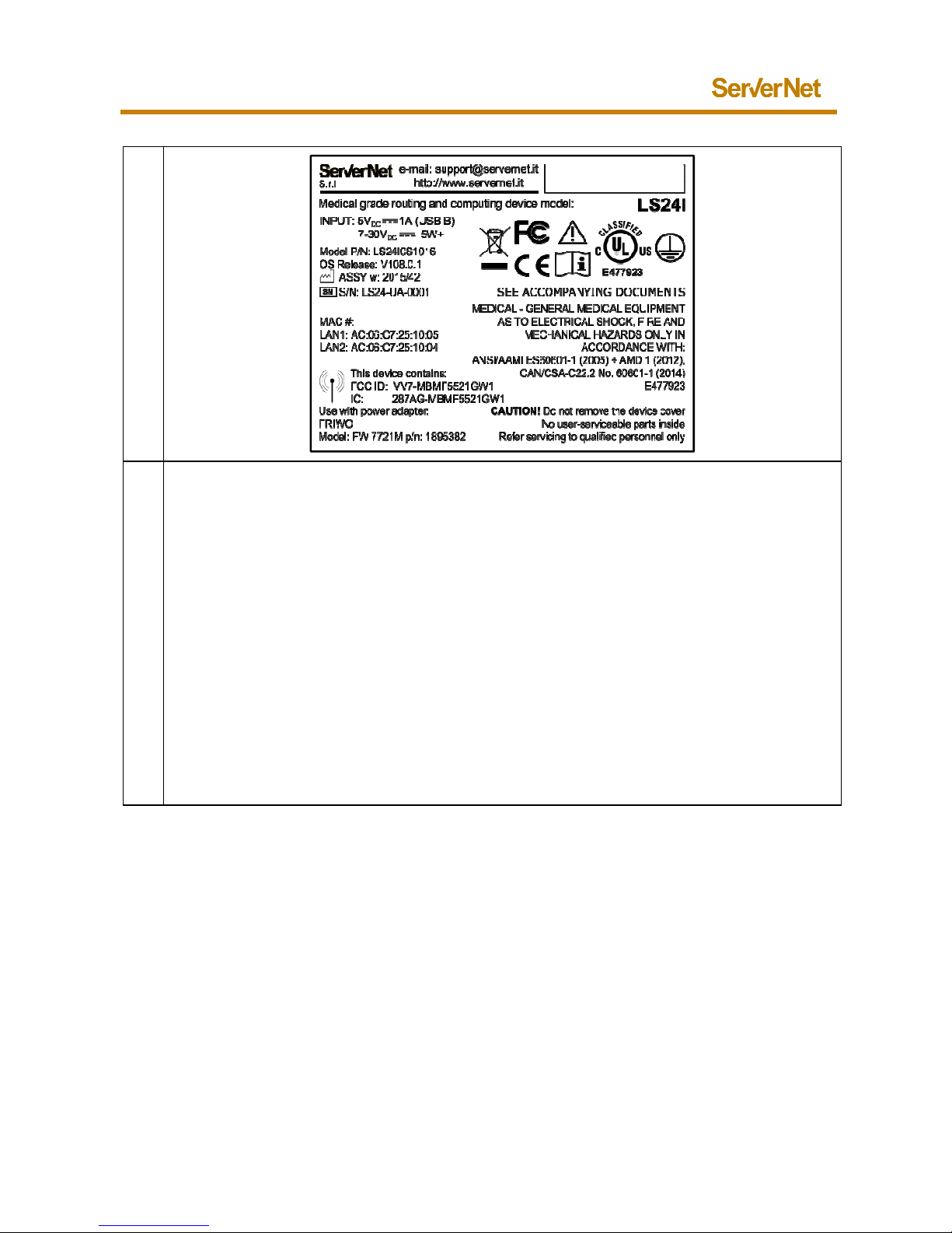
Copyright ServerNet S.r.l. 2015-2016, All Rights Reserved
L
D
LS24M WiFi backside certification label
.
Dimensions: 65x50 mm.
Material: 3M 76751 silver.
Includes:
• web site and e-mail address for HW customer support
• input supply voltage
• Model P/N: indicates device product model
related to customer
features
• OS Release: indicates installed release for the OS
• ASSY week: indicates assembly week (YYYY/WW)
• S/N: indicates serial number
• MAC #s for LAN1, LAN2 and WiFi
• WiFi FCC ID and IC
• Label symbols
For Configuration support refer to
Configuration Distributor documentation
Please see “Controls and Indicators” to know the symbols in this label.
LS24I/M
18
selected
.
LS24I/M
19 LS24I/M User guide
Copyright ServerNet S.r.l. 2015-2016, All Rights Reserved
L
D
LS24M
3G-UMTS backside certification label
.
Dimensions: 65x50 mm.
Material: 3M 76751 silver.
Includes:
• web site and e-mail address for HW customer support
• input supply voltage
• Model P/N: indicates
device product model related to customer selected
features
• OS Release: indicates installed release for the OS
• ASSY week: indicates assembly week (YYYY/WW)
• S/N: indicates serial number
• MAC #s for LAN1 and LAN2
• 3G/UMTS FCC ID and IC
• Label symbols
For Configuration support refer to Configuration Distributor
documentation
Please see “Controls and Indicators” to know the symbols in this label.
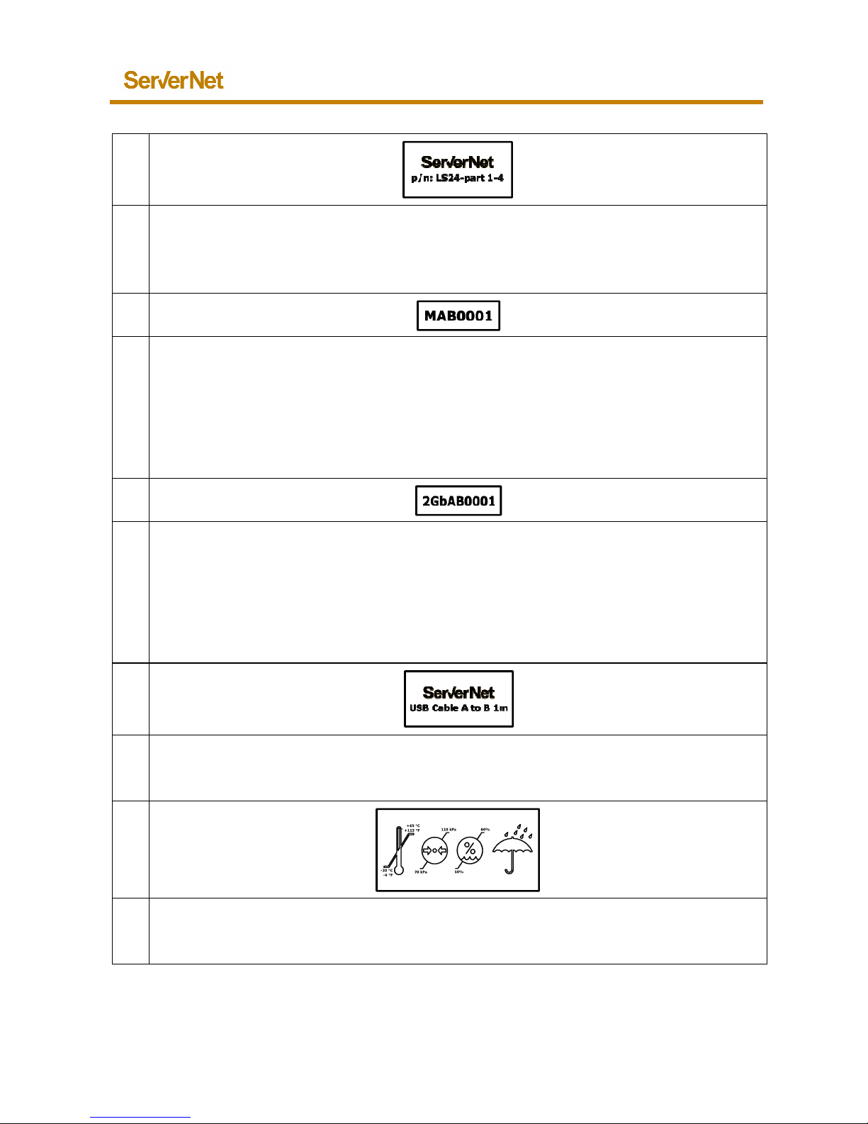
L
D
Package
label
.
Dimensions: 30x15 mm.
Material: polyester.
Includes:
•
Model P/N: indicates device product model related to customer selected
features
• ASSY week: indicates assembly week (YYYY/WW)
• S/N: indicates serial number
Apr, 2016
.
Apr, 2016 LS24I/M User guide
Copyright ServerNet S.r.l. 2015-2016, All Rights Reserved
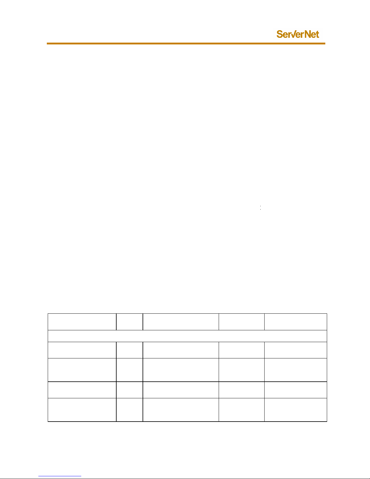
L
D
Bracket identification label
.
Dimensions: 20x10 mm.
Material: 3M 76751 silver.
Includes bracket part number.
L
D
B
ackplane b
oard identification
label
for batch tracking
.
Dimensions: 15x5 mm.
Material: polyester.
Includes:
• Board type: M: single power, I: double power
• Batch reference: 2 capital letters
• Progressive number 4 digits
L
D
CPU identification
label
for batch tracking
.
Dimensions: 15x5 mm.
Material: polyester.
Includes:
•
Board type: 1Gb: standard memory, 2Gb: extended memory
• Batch reference: 2 capital letters
• Progressive number 4 digits
L
D
USB A to B
1m
identification label
.
Dimensions: 20x10 mm.
Material: 3M 76751 silver.
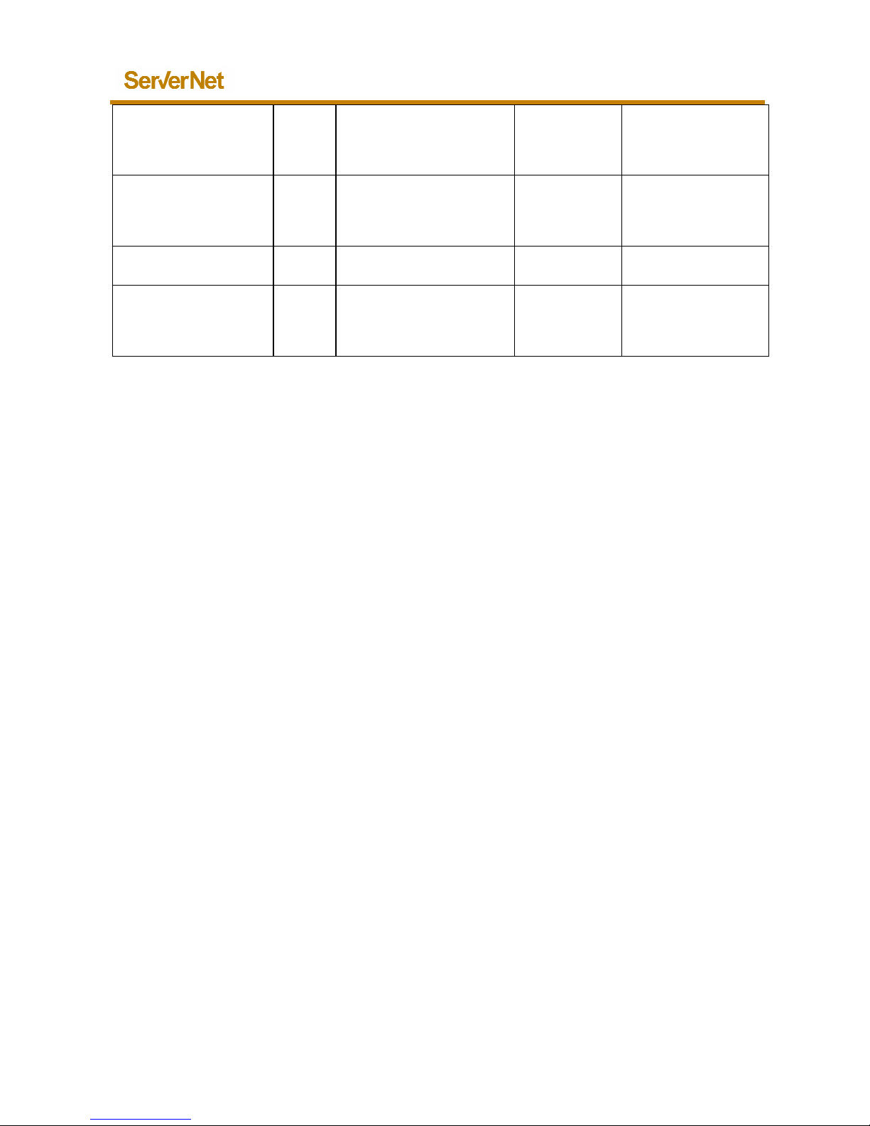
L
D
External indications:
transportation and storage
.
Dimensions: 30x15 mm.
Material: polyester.
LS24I/M
20
LS24I/M
21 LS24I/M User guide
Copyright ServerNet S.r.l. 2015-2016, All Rights Reserved
1.6. Controls and Indicators
LS24I/M is designed to be ON and running when connected to an external
power source. That’s why
connecting the device to a USB power source
plugging the USB A to B power cable connectors
, or plu
cable into the 7-30
V DC power connector, the device wakes
immediately
, loads the OS and the Configurations previously loaded
For more details about power supply management
you can
following chapter 5.
1.6.1. LED Indicators
IMPORTANT.
The following table represents indicator
meanings for device
hardware is OFF or when is running with only the OS
installed
third part Configuration loaded.
When a third part Configuration is loaded on the LS24I/M
,
OS to set all the parameters required to
implement
functionalities. In this case, COM LED
indicator meanings can be
completely mapped by the third part Configuration.
Refer to third part Configuration
specific documentation from the
Configuration Distributor to know COM indicator map
ped
running mode.
Indicator
Device
status
Action
Related LED
color
Both LS24I and LS24M
Battery charging
LED
ON/OFF
Battery charging
process running
Steady
orange
Battery charging
LED
ON/OFF
Battery failure
Flashing
orange
Battery charging
LED
ON/OFF
Battery fully charged
off
Status
LED ON Power mode check,
device start up and OS
loading
Flashing
Orange
Apr, 2016
gging the power
up
.
see the
LED when
without any
it is used by the
specific device
on hardware
Meaning
Battery in charge
Battery failure:
call internal
support
Battery fully
charged
Device wake
-
up
process and OS
loading
Apr, 2016 LS24I/M User guide
Copyright ServerNet S.r.l. 2015-2016, All Rights Reserved
Status
LED ON End setup
Flashing
Orange
turns fading
flashing Blue
Status
LED ON Boot error
Flashing
Orange for
more than
20 seconds
Status
LED ON OS critical failure
Steady red
COM LED
(1-4)
(indicates port status
without Configuration
loaded)
ON Plugging cable without
Configuration loaded
Steady Red
IMPORTANT.
Mobile portable operation supported only by the battery
is not a
use case for LS24I/M.
B
attery only power is for a limited out of power use or when temporary
more power than a nominal power source is needed.
Battery charging/not charging indicator is provided
by the battery
charge LED.
A complete battery
status and charge level is available trough the
web interface.
1.6.2. Audio indicators
LS24I/M includes an audio buzzer.
Sound indicator is not used in any part of OS
boot and run
Configurations.
It is designed to be usable by third part Configurations.
Refer to third part Configuration specific documentation from the
Configuration Distributor to know audio buzzer
indicator mapped on
hardware running mode.
LS24I/M
22
End OS loading,
device switch in
running mode
Device boot
process failure
Device OS critical
failure
Device connection
can’t be
recognized: call
internal support
n intended
on
device
ning without
LS24I/M
23 LS24I/M User guide
Copyright ServerNet S.r.l. 2015-2016, All Rights Reserved
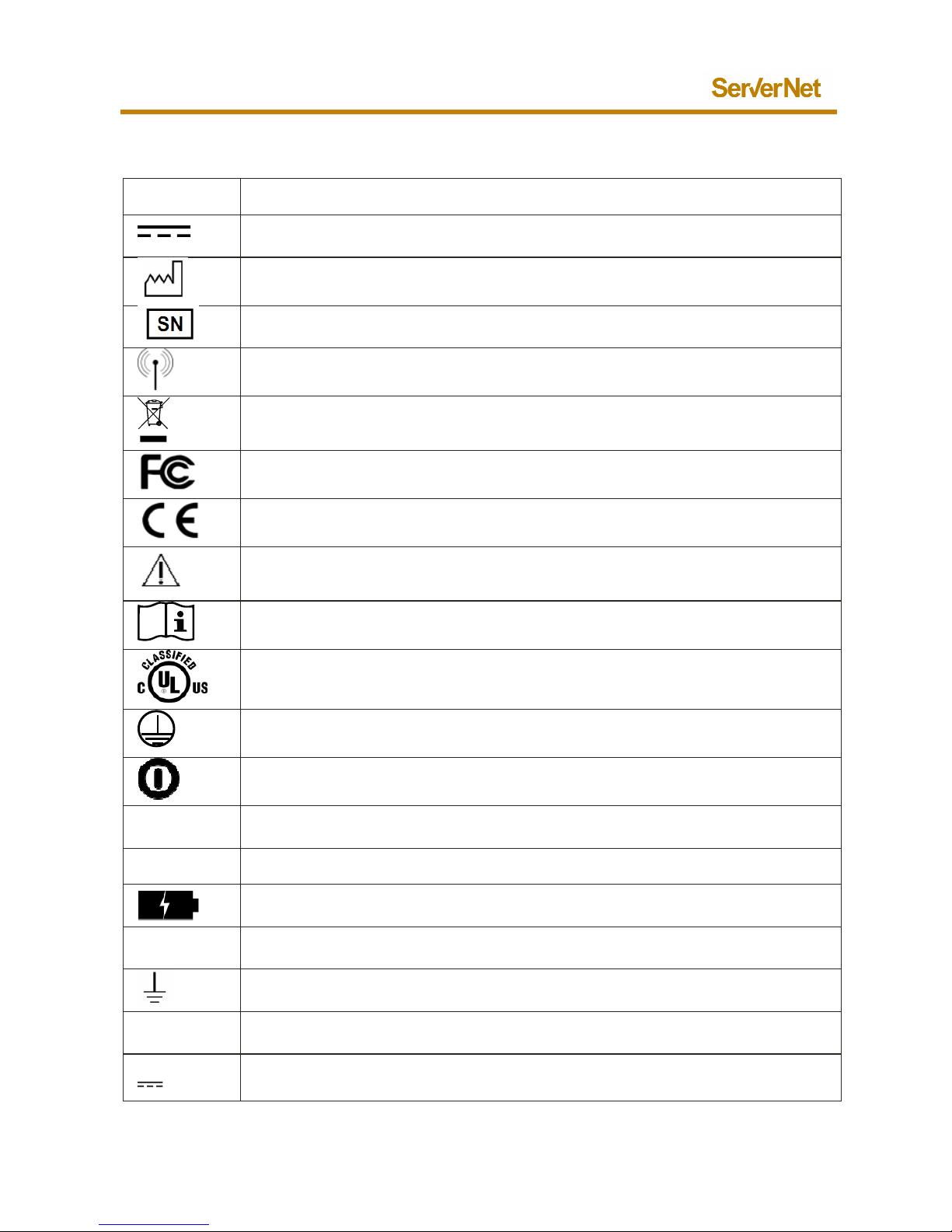
1.6.3. Symbols
Symbol
Description
DC power supply connector
Assembly date
Serial number
Radio source inside
WEEE symbol for electronic device disposal
Device compliant to requirements of the Federal Communications Commission
Device compliant to product European Directives
Attention. Consult accompanying documents.
Refer to User Manual.
Refer the user to the proper instruction manual
UL Certification mark
for US and Canada
Class 1 insulation device
ON/OFF button with complete device power off. Press and hold for 3 seconds
LAN1
,
LAN2
Network
communication connections
USB
USB Host connection
Battery on charge
LED
USB
PWR
USB power connector
Earth ground
COM1
, ...,
COM4
Serial communication connections
7-30
V 7-30 V DC industrial power connector (only for LS24I)
Apr, 2016
Apr, 2016 LS24I/M User guide
Copyright ServerNet S.r.l. 2015-2016, All Rights Reserved
1.7. ServerNet’s Responsibilities
ServerNet is responsible for the LS24I/M safety,
reliability and performance
while the following is met:
• Readjustments or repairs or maintenance
are carried out by
authorized and qualified personnel.
• The equipment is used in acc
ordance with instructions
use.
LS24I/M
24
ServerNet
and intended
LS24I/M
25 LS24I/M User guide
Copyright ServerNet S.r.l. 2015-2016, All Rights Reserved
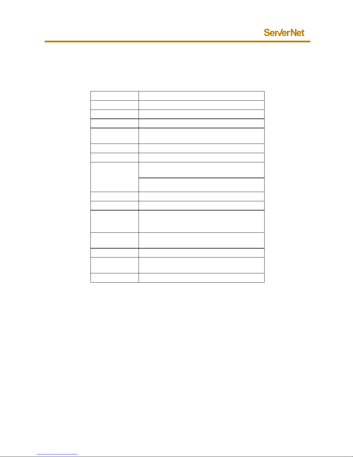
2. LS24I/M features
(*)
2.1. LS24I/M main features
(*)
CPU ARM9 400MHz low power
Memory
2/4 GBit D
RAM
/NAND
Storage
MicroSD memory socket
Ethernet
2 x RJ45 10/100Mbps Ethernet LAN
Wireless
Internal sockets for
WiFi or 3G/UMTS
,
BT4.0 wireless communication
USB (host)
USB
A
2.0 480 Mbps
Serial
4 x RS232 serial ports (RJ45)
Power
5V–500mA or 5V
-
1000mA USB type B pwr
connector
7-30
V 5W DC power supply connector
(only for LS24I)
Battery
Lithium Battery
1750 mAh Medical Grade
Operating
-
20°C / + 60
°C
Op.
with
battery
(in
hospital)
10°C / + 4
0°C
(hospital minimum/maximum
temperature
conditions)
Recommended
battery charge
0°C / + 45°C
Storage
-
20°C / + 45°C
Body case size
l w h
110 x 112 x 36 mm
(without antennas)
Cooling
Fanless cooling: no moving parts
(*)
Features can be modified every time by ServerN
et depending on component
and product updates without notice
Apr, 2016
and
supply conditions

Apr, 2016 LS24I/M User guide
Copyright ServerNet S.r.l. 2015-2016, All Rights Reserved
2.2. LS24I/M internal accessories
(*)
Storage
16 GByte MicroSD
(Class 4 or 10)
Other microSD card with different capacity
alternatives (4, 8, 16, 32, 64,… GB) and
speed class (4, 10,…)
Wireless
WiFi 802.11 b/g/n 2.4 GHz 150 Mbps
2 x dip 2.4 – 5.8 GHz 2.15 –
5 dBi antenna
BT 4.0 Low Energy expansion module
(**)
GSM/GPRS/3G Module with GPS
(**)
(replaces WiFi Module)
2 x dip pentaband GSM/GPRS/UMTS
terminal antenna
(*)
Features can be modified every time by ServerNet depending on component supply conditions
and product updates without notice
(**)
Optional item. Availability depends on device model and configuration
LS24I/M
26
(**)

LS24I/M
27 LS24I/M User guide
Copyright ServerNet S.r.l. 2015-2016, All Rights Reserved
3. LS24I/M Overview
3.1. LS24I front connectors
3.2. LS24M front connectors
On/Off
button
Eth Lan1
RJ45
Eth Lan2
RJ45
USB A
2.0
USB B
PWR
Status LED
multicolor
Battery
charging LED
On/Off
button
Eth Lan1
RJ45
Eth Lan2
RJ45
USB A
2.0
USB B
PWR
Status LED
multicolor
Battery
charging LED
Apr, 2016
7-30V
DC pwr

Apr, 2016 LS24I/M User guide
Copyright ServerNet S.r.l. 2015-2016, All Rights Reserved
3.3. LS24I/M rear connectors
3.4. LS24I/M front rear top view
Serial
1
RJ45
Serial
2
RJ45
Serial
3
RJ45
Serial
4
RJ45
WiFi
SMA
WiFi/BT
COM LED
multi
color
Protective Ground
M3 nut
LS24I/M
28
SMA

LS24I/M
29 LS24I/M User guide
Copyright ServerNet S.r.l. 2015-2016, All Rights Reserved
4. LS24I/M Mounting Options
4.1. Bracket mounting option
To allow device mounting
in vertical orientation (for example wall
mounting) a standard bracket is provided.
ServerNet suggests mounting the bracket of your
device with a vertical
orientation in order to improve device stability.
Use two screws and two
rawplugs for secure fixing.
Apr, 2016

Apr, 2016 LS24I/M User guide
Copyright ServerNet S.r.l. 2015-2016, All Rights Reserved
Since LS24I/M has
more or less square very small dimensions,
also mounted also horizontal
ly. In this case it is strictly recommended to
use a cable tie to avoid device unlocking.
LS24I/M
30
it can be

LS24I/M
31 LS24I/M User guide
Copyright ServerNet S.r.l. 2015-2016, All Rights Reserved
For bracket wall mounting, choose
the right screws and rawplugs
depending on the specific features/material of the wall
in order to allow a
durable mounting (some examples below).
To the bracket it can also be screwed a small
element to extend mounting
options to DIN bar, pole clamp
or other mechanical elements
In the upper part of the bracket there is a small
hole to allow
locking to the mounting bracket using a beaded cable tie
(*)
.
In this case, to remove the device it should be necessary to unlock the
removable tie or to cut the zip tie
before extracting the device from the
bracket.
Beaded and zip cable ties are not supplied with LS24I/M.
(*)
Not included into the package. Option to be evaluated separately.
IMPORTANT.
Choose features of your
component compliant with rules of your specific
implementation and environment of use.
Apr, 2016
(*)
.
easy device
or a cable-zip tie

Apr, 2016 LS24I/M User guide
Copyright ServerNet S.r.l. 2015-2016, All Rights Reserved
4.2. Velcro Mounting option
It is also possible to use velcr
o system to tie the device to other
or external supports. In this case mounting
bracket is not needed.
Medical grade velcro is not supplied with LS24I/M
since length and
dimension are related to specific customer
implementation
IMPORTANT.
Choose features of your component compli
ant with rules of your specific
application and environment.
LS24I/M
32
devices/PC
.

LS24I/M
33 LS24I/M User guide
Copyright ServerNet S.r.l. 2015-2016, All Rights Reserved
5. Important preliminary operations
Before starting the C
onfiguration of your LS24I/M be sure that the battery
is fully charged.
Do this also if your device was inactive or configured and never used for
long time (3 months or more). Do this also if
the internal
completely discharged.
Following the instructions in chapter 6.4
“Battery charging”
device in charge with a wall power adapte
r and wait until the battery LED
will switch off (battery fully charged).
IMPORTANT:
To allow a longer life of your device battery,
put in charge all your
devices every 3 months following the
instructions
“Battery charging”.
6. Starting with LS24I/M
This device is a network controlled
routing and computing device
typical I/O device operates or have meaning
ful use with the device
monitor, keyboard, mouse, audio).
LAN/COM/USB(host) ports are only for
data exchange and/or
communication purposes.
Device can be remotely monitored as explained in the following session
“Using LS24I/M” in chapter 0.
No video signal can be received/listened directly from this kind of device.
Only Status LED is designed to give feedbacks while in
running mode.
Since LS24I/M generally works together with other
external
LS24I/M is designed to be ON and running when
it has USB B or
power source active.
LS24I/M internal battery is intended only as temporary
power backup
additional power source to support device in case of
temporary power
source failure, low power mode (5V-
500mA) or temporary energy peak
demands for typical wireless communication.
Apr, 2016
a
battery is
, put the
inactive
in chapter 6.4
: no
(like
OS loading or in
devices,
7-30V DC
or as
Apr, 2016 LS24I/M User guide
Copyright ServerNet S.r.l. 2015-2016, All Rights Reserved
By design, the LS24I/M
keeps the battery fully charged or in charge
time including when it’s powered off.
By design:
• if LS24I/M is OFF:
plugging the USB B power cable both into a power
adapter connector and into a device USB connector, or plugging the
power cable into the 7-30V DC power connector
(only for LS24I)
device wakes up, powers on immediately;
• if LS24I/M is
powered by the battery and on running state (
plugging the USB B power cable both into a power adapter connector
and into a device USB connector, or plugging the power cable into the
7-30V DC power connector, the device continue
to stay ON
probably will start charging its internal battery
(see battery charging
LED);
• if LS24I/M is powered by external power source (
ON
source is interrupted: LS24I/M will continue run
ning
battery can support it or when the third part
Configuration sets
shutdown or a sleep level. In case of power
being available again to
the device, the device will restart if shutdown or will continue running
if no shutdown process has been initiated.
In case of LS24I/M low internal battery charge level, it
will
and some portion of the memory will still maintain their functionality.
Following the complete battery discharge, w
hen LS24I/M is re
external power sources, it boots
up automatically
instructions in chapter 6.4 “Battery charging”
for device internal
battery charge when it is completely discharged.
For LS24I/M battery charging status, refer to
the following chapter
IMPORTANT.
The USB adapter whose part number is listed as accessory (Friwo USB
power adapter: 1895382), is the one used during UL certification process.
LS24I/M is considered by UL as “Classified” device
compliant with 60601
3.1 Edition only if used together with this power adapter.
LS24I/M
34
at any
, the
ON):
and most
) and external
until the internal
a
shut down. RTC
-powered by
. Follow the
6.4.
-1
LS24I/M
35 LS24I/M User guide
Copyright ServerNet S.r.l. 2015-2016, All Rights Reserved
6.1. Using the ON/OFF button
By design the LS24I/M powers on when connected
to a
source, the ON/OFF button is designed to be used
as explained in the
following table with respect to the specific device version.
Device
model
Device
status
Power source
ON/OFF button action
LS24I
ON 7-30V DC
external power
active
Pressing and holding the ON/OFF button, you remove
completely device power source. When you leave the
ON/OFF button, device restarts immediately using
external power. Battery is
eventually
LS24I
ON
USB
B pwr
external power
active
Pressing and h
olding the ON/OFF button, you remove
completely device power source even if USB connector
is plugged and battery has charge. Device switches
off. Battery is eventually
in charge.
LS24I
ON
Internal battery
Pressing and holding the ON/OFF button, you remove
completely device power source. Device switches off.
LS24I
OFF USB
B pwr
external power
active/internal
battery
Pressing and holding the ON/OFF button, device
switches on.
LS24I
OFF 7-30
V DC
external power
active
By desig
n: not possible
LS24M
ON
USB
B pwr
external power
active
Pressing and holding the On/Off button, you remove
completely device power source even if USB connector
is plugged and battery has charge. Device switches
off. Battery is eventually
in charge.
LS24M
ON
Internal battery
Pressing
and holding the ON/OFF button, you remove
completely device power source. Device switches off.
LS24M
OFF USB
B pwr
external power
active/internal
battery
Pressing and holding the ON/OFF button, device
switches on.
6.2. Using USB type B power port
Take the USB cable A to B: plug the A connector into the USB port of your
power source (for example from a wall power supply).
Connect the USB
type B connector on the LS24I/M power port.
When your USB power source is active, LS24I/M wakes
the OS and goes in running mode.
Apr, 2016
n active power
in charge.
up, boots, loads
Apr, 2016 LS24I/M User guide
Copyright ServerNet S.r.l. 2015-2016, All Rights Reserved
If the external USB power source goes down, LS24I/
M uses the battery
until it has adequate level of charge or
until it catches third part
Configuration sets for shutdown or for sleep level.
Powering up by USB power on transition cannot be voided or masked but
additional Configuration parameters
can be applied to shut down the
device again.
IMPORTANT.
Assure that you will be using a USB
power supply certified for your specific
use.
The USB adapter whose part number is listed
as accessory (Friwo USB
power adapter: 1895382), is the one used during UL
certification process.
LS24I/M is considered by UL as “Classified
” device compliant with 60601
3.1 Edition only if used together with this power adapter.
6.3. Using 7-30V power connector
(only for LS24I)
Take the connector from a 7-30
V DC source and plug it into the connector.
When you plug the 7-30V DC connector, LS24I
wakes up,
OS and goes in running mode.
Until the 7-30V DC
connector is plugged giving power to the device,
will stay on.
If the external 7-30V power source desists, LS24I
uses the battery until it
has adequate level of charge
or until it catches third part Configuration
sets for shutdown or for sleep level.
Powering up by 7-30
V power cannot be voided or masked but additional
Configuration parameters
can be applied to shut down the device again.
IMPORTANT.
Assure that you will be using a 7-30
V DC power supply certified for your
specific use.
LS24I/M
36
-1
boots, loads the
LS24I

LS24I/M
37 LS24I/M User guide
Copyright ServerNet S.r.l. 2015-2016, All Rights Reserved
6.4. Battery charging
By design LS24I/M works along
with other devices, LS24I
be turned on when it has USB B (on power transition)
or
source active.
LS24I/M internal battery is intended only as temporary power backup to
support
device in case of temporary power source failure
inadequate or insufficient external power level.
By design, the LS24I/M is maintaining the battery fully
cannot be changed by any option including powering of the device.
For LS24I/M battery charging status, refe
r to battery charging orange LED
on the front panel.
If battery charging LED
is ON, device is charging its battery; if it is OFF,
device is not charging its battery. No assumption about the battery level
should be made by the user without accessing LS24I/M web interface.
See the previous chapter 1.6.1 “LED
indicators” for more details on
charging LED information.
IMPORTANT
If
your device was inactive or configured and never used for a long
time (3 months or more) or its internal
battery is completely
discharged,
you need to restore battery charge condition
following steps:
• P
ut the device in charge using a wall power adapter.
• Since device switches on aut
omatically if powered, you must
press and hold the ON/OFF button in order to force device
switch off.
• Wait until the battery LED
switches off (battery fully charged).
You can now use your device: this procedure will avoid the
problems that might occur wi
th internal battery completely
discharged condition.
Apr, 2016
/M is designed to
7-30V DC power
or temporary
charged and this
battery
with the

Apr, 2016 LS24I/M User guide
Copyright ServerNet S.r.l. 2015-2016, All Rights Reserved
6.5. Turning on LS24M:
OS loading and status LED options
Plug the power source connector on the LS24I/M
right connector to switch
on your device. It wakes-up, checks the
power supply mode and
the OS and Configuration parameters.
When power supply mode is checked, the ON/OFF status
LED
orange indicating device OS loading process.
When loading is completed (after 5-7 seconds)
and device is
mode, status LED is fading flashing blue.
See the previous chapter 1.6.1 “LED indicators”
for more details on status
LED information.
At any time during the boot process a problem arises,
status LED
flashing red.
LS24I/M
38
then loads
turns flashing
on running
starts

LS24I/M
39 LS24I/M User guide
Copyright ServerNet S.r.l. 2015-2016, All Rights Reserved
7. Using LS24I/M
For information about using the LS24I/M with all
their features and
possibilities refer to the Device Operating System
User’s Guide of your
device.
8. Accessing the LS24I/M
For information about accessing the LS24I/M with all their features and
possibilities refer to the Device Operating System User’s Guide of your
device.
9. LS24I/M OS use and c
onfiguration
To explain how to set
all the features of your LS24I/M device, refer to the
“Device Operating System User’s Guide”.
10. System recovery
To explain how to recovery
your LS24I/M device, refer to the “
Operating System User’s Guide” or refer to:
http://www.servernet.it/web/support
11. Battery removal
LS24/M has an internal lithium battery. This part is not user serviceable.
Apr, 2016
Device
Apr, 2016 LS24I/M User guide
Copyright ServerNet S.r.l. 2015-2016, All Rights Reserved
To remove or substitute the battery refer to
authorized and qualified
personnel or contact ServerNet’s personnel at
support@servernet.it
12. LS24I/M storage
To assure a correct storage condition for your LS24I/M, please respect the
storage conditions as listed on the previous table on chapter
indicated on the related label.
To allow a correct internal battery storage condition, s
tore
with its internal battery at 50% capacity. Every 4-
6 months, cycle (full
charge / full discharge) and charge the battery back to 50% before placing
your device back into storage.
13. Disposal of the Product
Obsolete or inoperative LS24I/M
units must be disposed of properly as
electronic waste in acco
rdance with all current disposal regulations of your
country / province / state / county / municipality.
14. User manual download
You can find this manual together with the OS user manual at:
www.servernet.it/download/
LS24IM_HW_UserManual.pdf
LS24IM_OS_UserManual.pdf
LS24I/M
40
.
2.1 and
your LS24I/M

LS24I/M
41 LS24I/M User guide
Copyright ServerNet S.r.l. 2015-2016, All Rights Reserved
ServerNet S.r.l.
Località Padriciano, 99
34149 Trieste (Italy)
LS24I/M User guide
Copyright ServerNet S.r.l. 2015, All Rights Reserved
Apr, 2016
 Loading...