

serverLink SL-KX-300 Quick Installation Manual
SL-KX-300 ServerLink Cat 5 KVM Extender VGA, USB & PS/2 up to 300mtr
1
Quick Installation Guide
SL-KX-300
ServerLink CAT5 KVM Extender VGA, USB & PS/2
Transmitter (TX) Unit
Receiver (RX) Unit
DUCTION
INTRODUCTION
The SL-KX-300 CAT5 KVM Extender can extend your keyboard,
monitor and mouse up to 300mtr away from your computer on a
single CAT 5 or CAT 6 UTP cable.
The CAT5 KVM Extender comprises two distinct units - the
Receiver (RX) Unit and the Transmitter (TX) Unit. The Transmitter
includes local console ports and allows a user to access the
computer at the local end, while also extending its keyboard, mouse
and video up to 300mtr to the Receiver unit at the remote end.
The Receiver Unit has a built-in 2 port KVM switch, and therefore
can also be connected to another computer at the receiver end and
perform switching between the remote computer (connected to the
TX) and the local computer (connected to the RX).
Applications include remote access of computers or servers for
security reasons, factory floors or warehouses not environmentally
suited to a computer or point of sale applications where space for a
computer is limited. It allows the user to manage and control the
computer at both locations together with the capability of switching
between the original computer and a second computer on the
Receiver end.
Package Contents
Transmitter (TX) Unit x 1
Receiver (RX) Unit x 1
3-in-1 VGA/USB/PS2 KVM Cable x 2
USB Type A to Type B Cable for Firmware Upgrade x 1
Power Adapters (DC5V 2A) x 2
This Quick Installation Guide x 1
The front and back panels are where the various connectors are
located on the two pieces of the CAT5 KVM Extender. Before you
connect these two units to any computer, cabling accessories or
peripherals, you should get a glimpse of the main connectors you
are going to encounter when setting up the system.
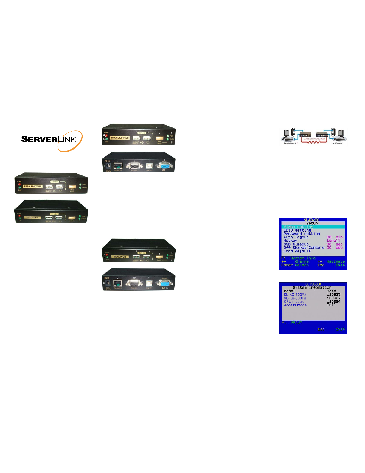
Transmitter (TX) Unit - Front-Panel
Transmitter (TX) Unit – Back-panel
Transmitter Unit (Local End Connection)
[TX – Front-panel]
a. Power LED (Lit when power is on)
b. Link LED (Lit when link is on)
c. USB keyboard connector
d. USB mouse connector
e. Select Button for Receiver Mode (View Only/Full
Access/Access Denied)
f. Video LED (Lit when Remote Console monitor is on)
g. Control LED (Lit when Control of Remote Console is on)
[TX – Back panel]
h. Power jack (DC5V 2A, centre-positive)
i. CAT5 Extension Port (RJ-45, connect to the Receiver Unit
via a CATx UTP cable up to 300mtr max.)
j. Computer port (HD15 VGA, connect to the Local computer
using included 3-in-1 KVM cable)
k. Upgrade port (USB Type B, dedicated for firmware upgrade)
l. Console Video port (HD15 VGA, connect to monitor)
Receiver (RX) Unit – Front panel
Receiver (RX) Unit – Back panel
Receiver Unit (Remote End Connection)
[RX-front panel]
1. Power LED (Lit when power is on)
2. Link LED (Lit when link is on)
3. USB keyboard connector
4. USB mouse connector
5. Toggle Button for Local / Remote Computers
6. Local Computer LED (Lit when Local computer active)
7. Remote Computer LED (Lit when Remote computer active)
[RX-back-panel]
8. Power jack (DC5V 2A, centre-positive)
9. CAT5 Extension Port (RJ-45, connect to the Receiver Unit
via a CATx UTP cable up to 300mtr max.)
10. Computer port (HD15 VGA, connect to the Local computer
using included 3-in-1 KVM cable)
11. Upgrade port (USB Type B, dedicnated for firm ware u pgrade)
12. Console Video port (HD15 VGA, connect to monitor)
INSTALLATION
Before you install the two pieces of the CAT5 KVM Extender, you
should have these items on the checklist ready:
1. The computer for extension should be one with either PS/2
or USB interfaces.
2. Prepare 1 or 2 sets of keyboard, mouse, monitor - 1 set for
console 1 (on the TX unit) and the other set for console 2 (on
the RX unit ).
3. If using a monitor on both sides, the two monitors used (one
on the TX side and the other on the RX side) for display
should be of the same native resolution to ensure maximum
compatibility.
4. You should use standard keyboard and mice, since the
CAT5 KVM extender supports only standard 5 button mice
and keyboard. Any more advanced mouse/keyboard function
may or may not be supported by this CAT5 KVM extender.
5. Use good quality CATx UTP cable (max. 300mtr). Note that
good quality cable will give better video outcome over a
longer distance.
6. Any cabling distance longer than 300mtr will experience
more signal degradation. However, good quality cable can
reach even beyond the maximum 300mtr with satisfactory
results.
7. The choice of path of the CATx UTP cable should not only
take into account the shortest possible path, but also one
that is relatively far away from any significant
electromagnetic interference source.
Plan the layout path and deploy the UTP cable for extension
Step 1. Plan the path through which the CATx UTP cable will be
deployed across the distance between the Transmitter
and the Receiver. You should choose the layout path not
only based on the shortest possible length consideration,
but also on the least electromagnetic interference.
Step 2. Lay out the UTP cable according to your planned path.
Configure the Transmitter Console
Step 3. Connect one end of the CATx UTP cable to the CAT5
Extension port of the Transmitter. (connector i)
Step 4. Connect the power adapter to the Transmitter to power it
up before connecting any computer or cables to it.
(connector h)
Step5. Connect the computer to the Transmitter using the
included 3-in-1 KVM cable (connector j)
Step 6. Connect a USB keyboard, USB mouse & VGA monitor to
the Console ports (connectors c, d, and l).
Step 7. Power on the computer, and check the keyboard, mouse
& video are working before you proceed to the next steps.
Configure the Receiver Console
Step 8. Connect the other end of the CATx UTP cable to the
CAT5 Extension port of the Receiver (connector 9).
Step 9. Connect the power adapter to the Receiver to power it
up before connecting any devices to it. (connector 8)
Step 10. Set up Console 2: Connect a USB keyboard, USB
mouse & VGA monitor to the Receiver’s Console ports
(connectors 3, 4 and 12).
Step 11. Check the keyboard, mouse & video on Console 2 are
working.
Step 12. Adjust the video parameters to optimize the display
output (Refer to OSD Menu/Video section for details).
Step 13. You can connect a second computer to the Receiver if
needed: Connect the computer to the computer port
using the included 3-in-1 KVM cable (connector 10)
CAT5 KVM Extender Configuration Diagram
OSD Menu
The OSD Menu control is available only on the RX unit. To invoke
the OSD Menu, you should hit the following hotkeys:
Default Hotkey = [SCROLL] + [SCROLL] + [SPACE]
To navigate the OSD Menu, just use the following keys
Esc: Exit,
Left/Right cursor: change value in the menu
option
Up/Down Cursor: Navigate.
F10: Logout the OSD Menu (However, if the
password protection is not enabled, the Logout
feature will not be available)
OSD Main page
This is the OSD Main Menu and is the first page you will see when
you hit the keyboard hotkey [SCROLL] + [SCROLL] + [SPACE]
Main Menu
Press F1 for System Information OSD Menu
System Information Menu
SL-KX-300 ServerLink Cat 5 KVM Extender VGA, USB & PS/2 up to 300mtr
2
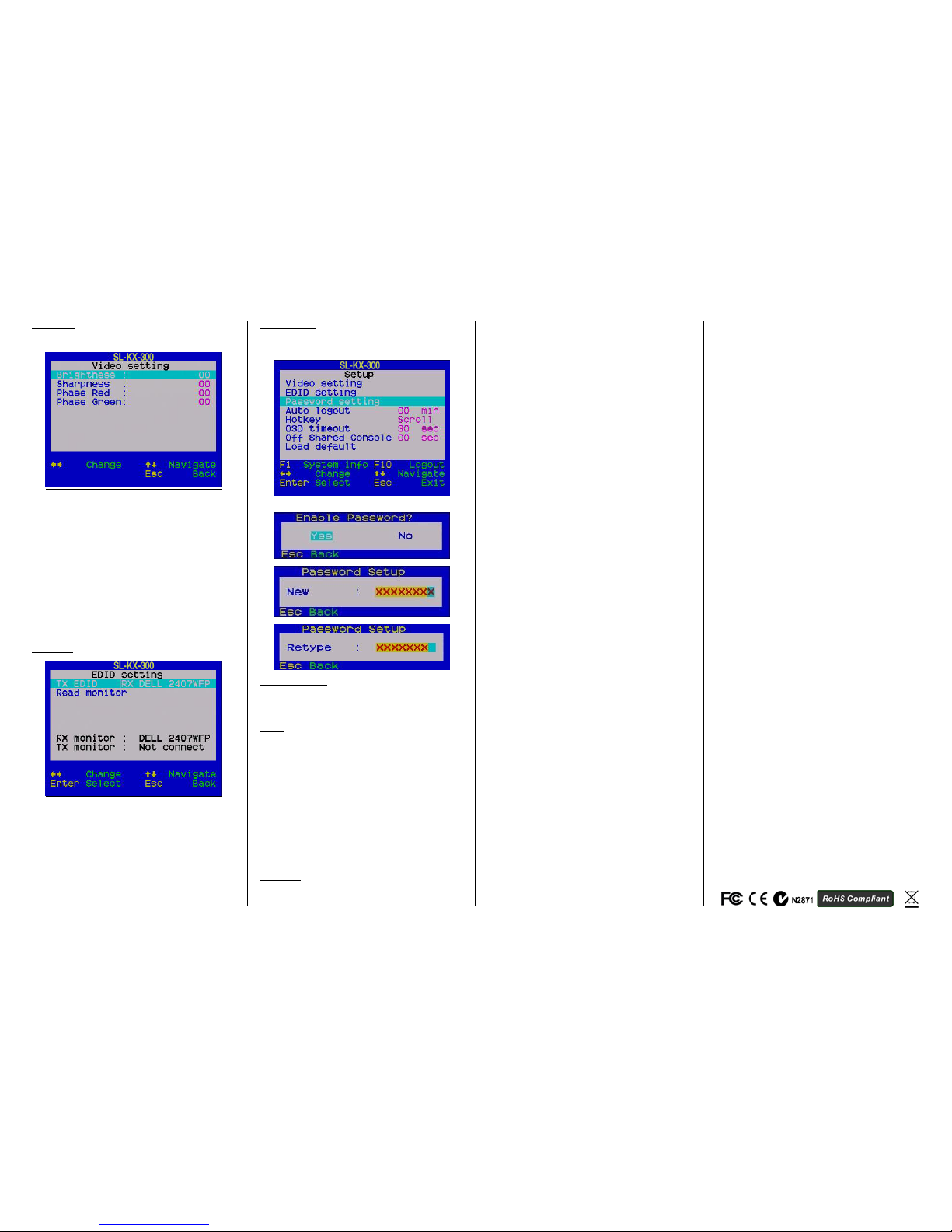
Video Setting
Configure the video settings such as Brightness, Sharpness and
skew compensation for Phase Red and Phase Green.
Video Setting Menu
Brightness: [0 ~ 63]
Adjust the Brightness of the Display on Receiver Console.
Sharpness: [0 ~ 63]
Adjust the Sharpness of the Display on Receiver Console.
Phase Red: [-31 ~ +31] specify the time delay for red colour.
Phase Green: [-31 ~ +31] specify the time delay for green colour.
The blue component colour is adjusted automatically in proportion
to the red and green. Users have no need to adjust the blue colour
themselves.
For a more detailed explanation of how to adjust your video display
parameters on the remote console, please refer to next section,
Optimize the Video Display on the Remote Console.
EDID Setting
EDID Setting Menu
TX EDID
You can select the TX EDID emulation data set to adopt - either
that of the monitor on the RX or the monitor on the TX unit. You can
use the Left / Right Arrow key to select. However, before you can
make the selection for the first time, you might need to read the
monitor EDID information by the Read Monitor option below.
Read Monitor
Reads the EDID configuration data from the monitors on the TX
and the RX & stores it for use for the EDID emulation on the TX unit.
Password Setting
Disable / Enable the password protection feature. If enabled, after
you log out or the Auto logout has timed out, you will be prompted
for the correct password before you can access the console again.
Password Setting Menu
Auto Logout: [0 ~ 10]
Disable / Enable the Logout timeout (0~10min, 0 = Disable).
The Auto logout time can be configured from 0 (Disable), with an
increment of 1, right up to 10 min. If the password protection is not
enabled, the Auto logout will not be available for use.
Hotkey: [Default is [SCROLL LOCK] + [SCROLL LOCK]
To change the preceding sequence hotkey, press, to select
your new hotkey - CAPS, F12 or NUM.
OSD Timeout: [0~60]
Configure the OSD timeout value (0, 20~...30~…60), with an
increment of 5 seconds, (0 = Disable).
Off Shared Console
Configured the Shared Console Control (Disable/Enable or adjust
the timeout value (0~30 seconds, 0= Disable)
If enabled, this function will lock control to the current user (either
on the TX or RX) until there is no activity for the timeout period. It
will then release control and the other user can gain access.
When this function is enabled, the Transmitter’s LED’s “Video” &
“Control” will flash, until the timeout period has expired.
Load Default
Load the factory default settings.
HOTKEYS AVAILABLE ON THE RECEIVER CONSOLE
Switch between Local/Remote Computer using Keyboard
Hotkey (on Receiver console only)
In addition to using the switching button on the front panel of the
Receiver to switch between the 1st and 2nd computer, you can also
use the keyboard hotkey:
Hotkey sequence = [SCROLL] + [SCROLL] + (y)
(y) = ,
(y) = , Local (2nd computer)
(y) = , Remote (1st Computer)
Change the Hotkey Preceding Sequence using Keyboard
Hotkey instead of OSD Menu (on Receiver console only)
To change the hotkey preceding sequence of your hotkeys, please
hit the following key commands from the keyboard on the RX unit.
Hotkey sequence = [SCROLL] + [SCROLL] + H + (y)
(y) = SCROLL, CAPS, F12 or NUM
Note that the hotkey preceding sequence setting on the RX
Console will also change the hotkey preceding sequence on the TX
Console.
HOTKEYS AVAILABLE ON THE TRANSMITER CONSOLE
Change the Remote Console ON/OFF/View Only mode (on
Transmitter console only)
While you are at the Transmitter Console, you can turn Remote
Console On/Off or make it View Only by the following:
Hotkey sequence = [SCROLL] + [SCROLL] + M + (y)
(y) = 1, 2, 3
(y) = 1, Full access (keyboard, mouse and video)
(y) = 2, Access Denied (no keyboard or mouse and blank screen)
(y) = 3, View only (only video, no keyboard or mouse control)
When the remote console is turned OFF, the video screen will
become blank and the keyboard and mouse will be disabled.
When the remote console is in View Only Mode, the user can only
see the screen while access to keyboard and mouse control are not
available.
Optimize the Video Display on the Remote Console
To achieve an optimized display output on the remote console (i.e.
the Receiver) you will need to adjust the various video parameters
such as Brightness and Sharpness in an optimized combination
that gives you the best video display.
Please follow the procedure below to achieve an optimized display
output on your remote console screen (on RX unit):
Step 1. Choose a video display content that you think will be
suitable to serve as a reference for the visual adjustment. You can
choose a document that integrates texts and graphics so that you
can use it as a reference to achieve an optimized video display for
either textual or graphical content on the Receiver video output.
One alternative can be the visual testing program provided by the
display card vendor.
Step 2. Adjust the Brightness and Sharpness - First, invoke the
OSD menu by hitting the hotkey, SCROLL + SCROLL + Space,
then go to the Video Setting submenu.
Next, adjust your video display for an optimized output. The
Brightness adjustment can help you to tune the picture luminance
as a whole to lighter or darker output that best suits your visual
perception. The Sharpness is the edge contrast that you will
perceive.
Adjust the Brightness: The brighter the picture, the more
luminance will be added to the picture as a whole.
Adjust the Sharpness: To add more sharpness to the
picture is to help you distinguish more detail out of the edges
of a line or shape.
When you have adjusted the Brightness and Sharpness to achieve
your desired level, you can then move on to adjusting the Red
Delay and Green Delay to achieve your optimized video output.
Step 3. Adjust the Red Delay and Green Delay: the Red, Green
and Blue are the primary colors that constitute our color perception
scheme on the monitor.
The CAT5 extender uses different wires in the UTP cable to carry
the signals of different primary colors. The different wires in the
twisted-paired cable are all slightly different overall lengths and the
longer the CATx cable, the greater the difference in length between
wires.
This difference in length causes the red, green and blue colours to
become out of sync. You will need to adjust the delay time for
certain colour signals on certain wires to make the three colour
signals arrive into the display in good sync.
The CAT5 KVM Extender requires you to manually adjust only the
Red delay and the Green delay - the Blue delay is automatically
tuned and optimized by the machine according to the other
concurrent video parameters.
The values of the Red delay and the Green delay will be limited
within a preset difference range. This means, whenever you try to
adjust either the value of the Red delay or the Green delay to be
outside of the allowable preset difference range as compared to the
value of the other colour delay, the other colour delay will be
automatically adjusted to be within the difference range to prevent
the video from being perceptibly disoriented.
With the Blue delay automatically tuned in relation to the other
colours and the Red and Green delays limited within a comfortable
difference range, the SL-KX-300 CAT5 KVM extender facilitates an
easier and more intuitive way for video optimization.
No Video Troubleshooting
Q. When I connect a monitor to the CAT5 KVM extender, it
does not display any video.
A. If you encounter no video or other display problems with a
specific monitor, you should try to copy the EDID information from
the smaller monitor among the local monitor and the remote
monitor to see if this can eliminate the display problem.
FCC: This equipment has been tested and found to comply with
Part 15 of the FCC Rules. Operation is subject to the following two
conditions:
(1) This device may not cause harmful interference
(2) This device must accept any interference received. Including
interference that may cause undesired operation.
CE: This equipment is in compliance with the requirements of the
following regulations: EN 55 022: CLASS B.
C-Tick: This equipment is in compliance with ACMA’s
Electromagnetic Compatibility (EMC) regulatory arrangements
under the Radiocommunications Act 1992.
RoHS: All contents of this package, including products, packing
materials and documentation comply with RoHS.
 Loading...