

serverLink SL-DKX-050 Quick Installation Manual
SL-DKX-050 ServerLink DVI KVM Extender over Cat 5 - DVI, USB KB & Mouse, Audio & 1 x USB 2.0 Device up to 50mtr
1
Rev. 1.2 Copyright© All rights reserved.
Quick Installation Guide
SL-DKX-050
ServerLink DVI KVM Extender over Cat 5, DVI, USB
KB & Mouse, Audio & 1 x USB 2.0 Device up to 50mtr
Transmitter Unit (TX)
Receiver Unit (RX)
INTRODUCTION
The SL-DKX-050 DVI Extender over Cat 5 can extend your
DVI monitor, keyboard, mouse, audio and a USB 2.0 device
up to 50mtr away from your computer over a two (2) CAT 5 or
CAT 6 UTP cables.
The CAT5 DVI Extender comprises two separate units - the
Receiver (RX) Unit and the Transmitter (TX) Unit.
With automatic EDID configuration, stereo audio support and
crystal clear video reproduction, the SL-DKX-050 is simple to
install, configure and operate.
Package Contents
Transmitter (TX) Unit x 1
Receiver (RX) Unit x 1
DVI-D Male to Male cable x 1
USB cable (Type A to Type B) x 1
USB to DC Jack Cable x 1
Power Adapter (DC5V 2A) x 1
This Quick Installation Guide x 1
Front & Rear Panel Connectors
The front and back panels are where the various connectors
are located on the CAT5 DVI KVM Extender. Before you
connect these two units to any cabling or devices, you should
familiarise yourself with these connectors to simplify
installation.
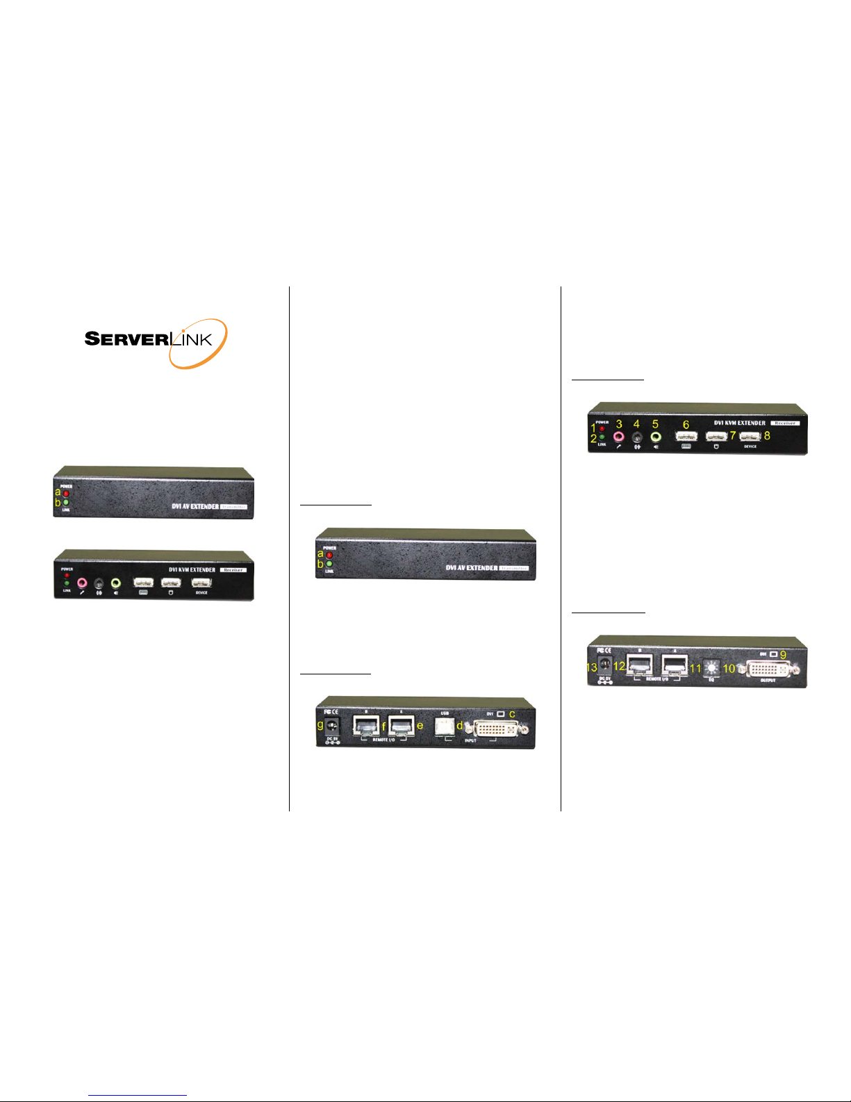
Transmitter Unit (TX) - Local
[TX - Front Panel]
Transmitter (TX) Unit – Front Panel
a. Power LED (Red) (Lit when the power is on)
b. Link LED (Green) (Lit when the link is on)
[TX - Back Panel]
Transmitter (TX) Unit – Back Panel
c. DVI input - connect to computer’s DVI output port
d. USB Port (USB Type B) - connect to PC USB port
e. RJ45 CAT5 Extension Port (A)
f. RJ45 CAT5 Extension Port (B)
g. Power Receptacle (DC5V 500mA, centre-positive)
Receiver Unit (RX) - Remote
[RX - Front Panel]
Receiver (RX) Unit – Front Panel
1. Power LED (Red) (Lit when the power is on)
2. Link LED (Green) (Lit when the link is on)
3. Microphone Jack
4. Line-in Jack
5. 3.5mm Stereo Audio Speaker Jack
6. USB Keyboard Port
7. USB Mouse Port
8. USB 2.0 Device Port
[RX – Back Panel]
Receiver (RX) Unit – Back Panel
9. DVI output - connect to DVI monitor
10. EQ (Equalizer) Port
11. RJ45 CAT5 Extension Port (A)
12. RJ45 CAT5 Extension Port (B)
13. Power Receptacle (DC5V 2A, centre-positive)
SL-DKX-050 ServerLink DVI KVM Extender over Cat 5 - DVI, USB KB & Mouse, Audio & 1 x USB 2.0 Device up to 50mtr
2
Rev. 1.2 Copyright© All rights reserved.
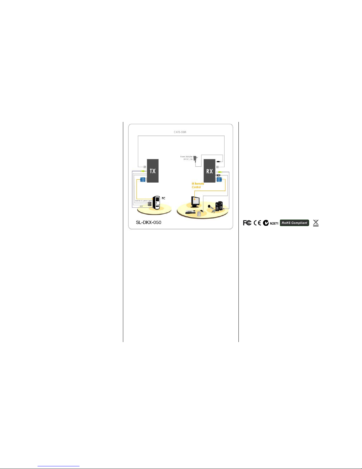
INSTALLATION
Configure the Transmitter Unit (TX) - Local
Front Panel (TX)
No cable connections required.
Back Panel (TX)
1. Connect one CAT 5 or CAT 6 cable to the Transmitter
RJ45 port A (e) and a 2nd Cat 5 or Cat 6 cable to the
Transmitter RJ45 port B (f)
2. Connect the Transmitter’s DVI port (c) to the computer’s
DVI output port using the included DVI cable
3. Connect the Transmitter’s USB port (d) to the
computer’s USB port using the included USB cable
4. Connect the USB to DC Jack cable to the Transmitter to
power it up (g)
Configure the Receiver Unit (RX) - Remote
Front Panel (RX)
1. Connect the Microphone to the microphone jack (3)
(Optional)
2. Connect the Line-in cable to the Line-in jack (4) (Only
when recording required.(Optional)
3. Connect the speaker to the stereo audio jack (5)
(Optional)
4. Connect a USB keyboard (6) and a USB mouse (7) to
the USB ports
5. Connect a USB 2.0 Device (8) (Optional)
Back Panel (RX)
1. Connect the DVI monitor to the DVI output port (9)
2. Connect one CAT 5 or CAT 6 cable to the Receiver
RJ45 port A (11) corresponding to the Transmitter A
3. Connect a 2nd Cat 5 or Cat 6 cable to the Receiver
RJ45 port B (12) corresponding to the Transmitter B
4. Connect the AC power adapter to the Receiver to power
it up (13)
5. If the remote monitor is blank or intermittently blank,
adjust the EQ (Equalizer) rotating switch (10) as needed
until a stable display is achieved
TROUBLESHOOTING
Q: I have connected all the cables correctly and powered on
the extender, however the monitor doesn’t display any video
image. How can I solve this problem?
A: If you encounter no video display, please adjust the
Receiver Unit’s EQ (Equalizer) rotating switch until a video
image is displayed.
Notes:
1. Use good quality CATx UTP cable (max. 50mtr). Note that
good quality cable will give better video outcome over a
longer distance.
2. The choice of path of the CATx UTP cable should not only
take into account the shortest possible path, but also one
that is relatively far away from any significant
electromagnetic interference source.
FCC
This equipment has been tested and found to comply with Part
15 of the FCC Rules. Operation is subject to the following two
conditions:
(1) This device may not cause harmful interference
(2) This device must accept any interferenc e received.
Including interference that may cause undesired operation.
CE
This equipment is in compliance with the requirements of the
following regulations: EN 55 022: CLASS B.
C-Tick
This equipment is in compliance with ACMA’s Electromagnetic
Compatibility (EMC) regulatory arrangements under the
Radiocommunications Act 1992.
RoHS
All contents of this package, including products, packing
materials and documentation comply with RoHS.
 Loading...