

Page 1

RoHS
Features and functions may be added or changed
after the manual was written. Please visi t our
website to download the latest version of manual
for reference.
◘
◘
HDBaseT 4K2K 4-Input HDMI CATx Gate Repeater
User's Manual
Page 2
Table of Contents
---------------------- Introduction
.................................................................................................... 1
I. Overview ............................................................................................................................ 1
II. Features ............................................................................................................................. 1
III. Package Content ......................................................................................................... 2
IV. Product Description ................................................................................................... 4
V. Installation ......................................................................................................................... 6
Device Connection .......................................................................................................... 6
Connection Pattern ......................................................................................................... 7
VI. LED Indicator ................................................................................................................ 8
VII. Operation ....................................................................................................................... 9
Push Button Control .................................................................................................. 9
IR Remote Control .................................................................................................... 13
------------------------ Serial Configuration
............................................................................... 15
I. Simple Serial Connection ........................................................................................... 15
II. GUI over Serial ............................................................................................................... 17
A. Installing Application ............................................................................................... 17
B. Uninstalling Application ......................................................................................... 17
C. Description & Operation ......................................................................................... 18
------------------------ Specification
............................................................................................. 24
Please read this manual thoroughly and follow the Installation procedures to prevent any damage to
the unit or any connecting device.
*
The final specifications are the actual product based.
*
Features and functions are subject to change since the manual was written.
Please visit the related website to download the latest version of manual for reference.
RoHS
Page 3

1
---------------------- Introduction
I. Overview
II. Features
Repeater function which can deliver HDMI signal to multimedia displays over a CAT5e/6 cable up to
100 meters
100BaseT Ethernet Pass-Thru enables simultaneously distribute HDMI and Ethernet streaming videos
from each source to each display
Advanced design which allows the device to be cascaded for multiple times
Provide various ways to control via
(1) Push buttons on the front panel
(2) IR remote controller
Duplicate or even add a second video signal to achieve multicast distribution that sends multiple sources
to multiple displays in separate locations
RS 232 Slide Switch for configuring two-way communication between the device, the transmitter, or the
receiver
Additional local input port(s) available on each device
Can be connected to the transmitter or receiver through LAN*
HDTV, 3D HDTV compatible; HDCP compliant and Blu-ray ready
Support resolutions up to UHD (3840 x 2160), Full HD 1080p, 2048 x 1152, Deep Color and HD Audio
formats
Bi-directional IR & Serial (depending on the model)
Ideal for receiving guests (for hotels and conference rooms) or digital signage (for airports or shopping
malls), surveillance cameras, whole-home networking, or point-to-point applications
Exclusive EDID Function
Multiple functions for EDID setting, like EDID Copy and EDID Pre-setting, ensuring accurate output
display
Enable separately learn Audio and Video EDID for multimedia/ Home Theater system integration
Read and store the EDID from the connecting display to the video extension
EGO (Advanced Auto-Sensing) Function*
Versatile port selection functions of Priority, Auto-sensing and Switch modes
User-friendly port switching via button pressing or priority setting
*(Depending on the model)
SERVEREDGE 4K2K HDMI CATx Gate Repeater transmits / Receives full uncompressed 3D HD video and
audio over CAT5e/6 cable up to 100 meters. It not only supports resolutions up to 4K2K (3840 x 2160), Full HD
1080p and 2048 x 1152, but supports Deep Color and HD Audio formats as well.
The optional Graphical User Interface (GUI) function makes control easier and more effectively. The
well-designed GUI can free users from giving complex commands. What’s more fantastic is that it allows you
to name and portray your source and display icons for user-friendly operation.
The advanced and inexpensive all-in-one connectivity technology only requires low-cost and handy CAT5e/6
cables, making SERVEREDGE 4K2K HDMI Gate Repeater perfect for occasions like receiving guests (for
hotels or conference rooms) and digital signage (for airports or shopping malls), etc.
Page 4

2
III. Package Content
Content Quantity
SW4I-03457-100
1
Power Adapter Set 1
IR Remote Controller 1
CD (User’s Manual + Software Utility) 1
Quick Start Guide 1
CATx Cable (1.5M) 1
Grounding Wire 1
Foot Pad Set 1
Page 5

3
You may also need
HDMI Cable (M-to-M) 1.8m for HDMI A/V source connection
Serial Cable (straight type, male-female)
Other transmitter and repeater
Other repeater(s)
Optional
IR Sensor Kit
RJ12 Cable + RJ12 to RS232 Adapter*
*Note:
If users want to use other RJ12 to RS-232 converter, please make sure that pin connection must follow what
showed in the following diagram.
Method 1:
Method 2:
Page 6
4
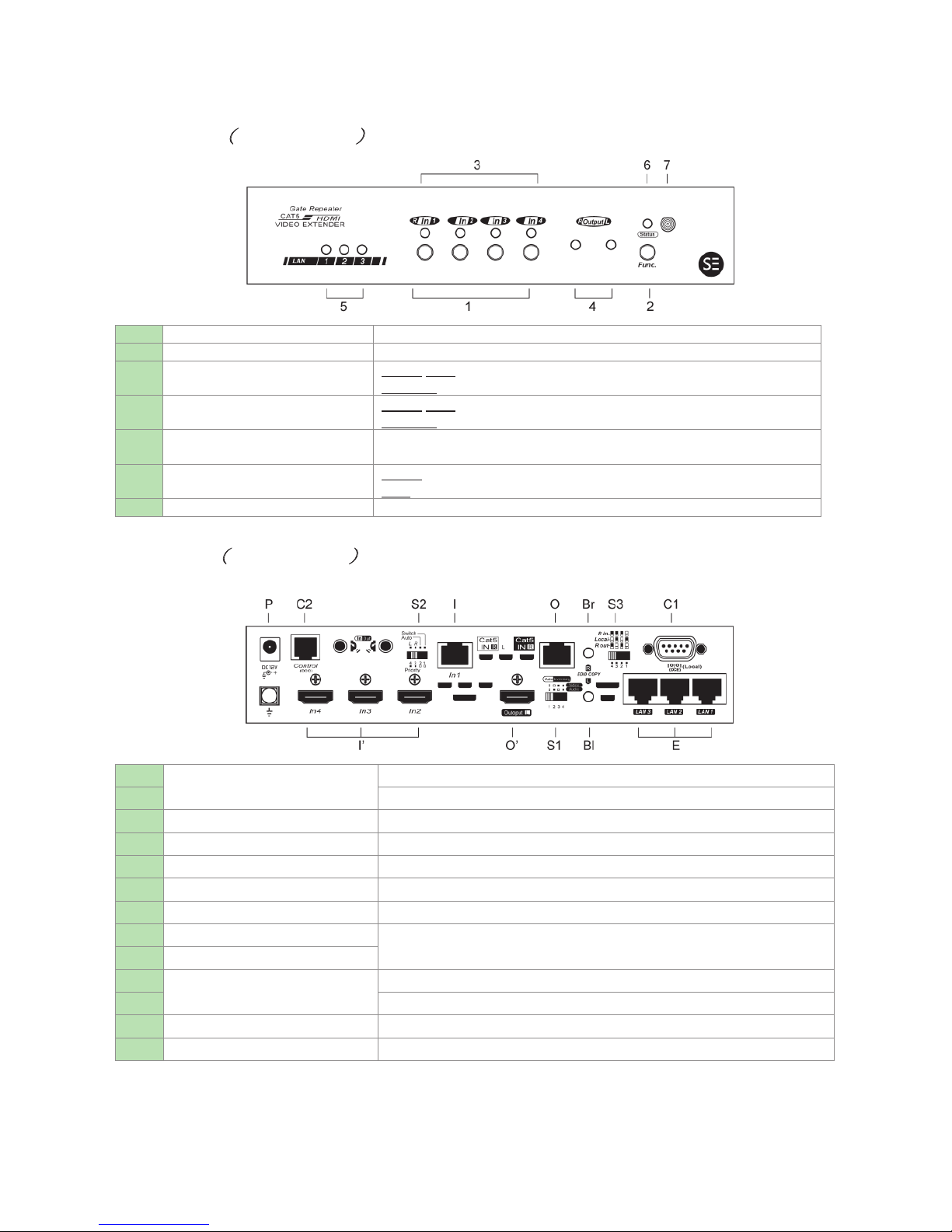
IV. Product Description
Front Panel (SW4I-03457-100)
1
Select Button
Port selection
2
Function Button
System Configuration
3
Input Port LED
Green/Blue: Port selected
Flashing: Programming
4
Remote Output LED
Green/Blue: Power on
Flashing: Programming
5
LAN Port LED
Orange: Link to Ethernet device
Off: Unlink
6
Status LED
Green: Power on
Blue: Stand-by mode
7
IR Sensor
IR remote controller sensor
Rear Panel (SW4I-03457-100)
I
Video Input Port
Connect to an HDMI source
I’
Connect to HDMI sources (depend on model)
Ro
Remote Output Port
Connect to a receiver
Lo
Local Output Port
Connect to an HDMI display
S1
EDID Setting Switch
See the diagram of EDID Setting Switch
S2
EGO Slide Switch
See the diagram of EGO Slide Switch
S3
RS232 Slide Switch
See the diagram of RS232 Slide Switch
Bl
EDID Copy Button (Local)
Copy EDID compliant display (Audio & Video)
Br
EDID Copy Button (Remote)
C1
Serial Port
Connect to PC for serial extension
C2
Connect to PC for serial console
E
RJ45 connector
Connect to Ethernet devices (depend on model)
P
Power Supply
Apply power to the unit
Page 7
5
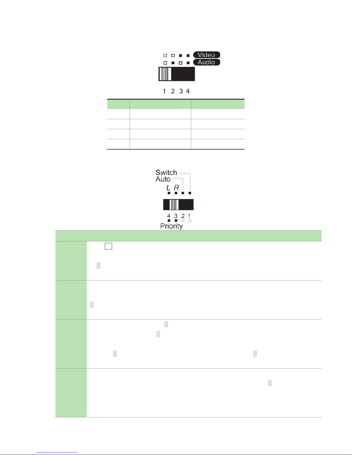
EDID Setting Switch
Mode Video Audio
1
Auto Auto (Min.)
2
Auto Inventory
3
Inventory
Auto (Min.)
4
Inventory
Inventory
EGO Slide Switch
Mode Description
Switch
Press Kn button to select Source-N; all monitors display Source-N
NOTE: When switching from other modes to Switch mode, all monitors display Source-1 (CATx
IN R). But if there’s no source detected in Source-1, it’s required to manually press the button
for other source selection.
Auto
System will automatically select the latest video source for display
NOTE: When switching from other modes to Auto mode, all monitors display Source-1 (CATx IN
R). But if there’s no source detected in Source-1, the system will automatically display the latest
video source.
Priority-R
Remote input source (CATx IN R) has the highest priority
Priority: Source-1 (CATx IN R) > Source-2> Source-3> Source-4
NOTE: When switching from other modes to Priority-R mode, all monitors display Source-1
(CATx IN R). But if there’s no source detected in Source-1 (CATx IN R), the system will
automatically display the next video source (follow Priority-R order).
Priority-L
Local input source (HDMI IN 2) has the highest priority
Priority: Source-2 (HDMI IN 2) > Source-3> Source-4> Source-1 (CATx IN R)
NOTE: When switching from other modes to Priority-L mode, all monitors display Source-2
(HDMI IN 2). But if there’s no source detected in Source-2 (HDMI IN 2), the system will
automatically display the next video source (follow Priority-L order).
Page 8
6
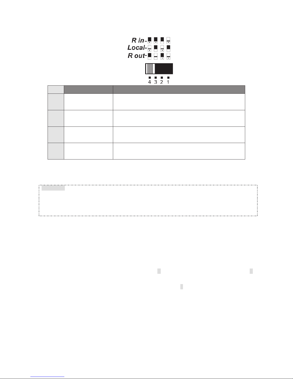
RS232 Slide Switch
Mode
Connection Description
1
R out connects to
Local
Two-Way Communication between the unit (Repeater) and
Receiver
2
R out connects to R in
1.Two-Way Communication between Transmitter and Receiver
2.Receiver can send commands to the unit (Repeater)
3
R in connects to Local
Two-Way Communication between the unit (Repeater) and
Transmitter
4
R in connects to R out
1.Two-Way Communication between Transmitter and Receiver
2.Tansmitter can send commands to the unit (Repeater)
V. Installation
WARNING!
● Prior to installation, ensure to power off all devices that will be connected to this system.
● Ensure that all devices you will connect are properly grounded.
● Place cables away from fluorescent lights, air conditioners and machines that are likely to generate
electrical noise.
● Please allow adequate space around the unit for air circulation.
Grounding
To prevent any damage to the product or any connecting devices, and to improve audio/video signal quality, it
is important to make sure that the extender systems are properly grounded.
Device Connection
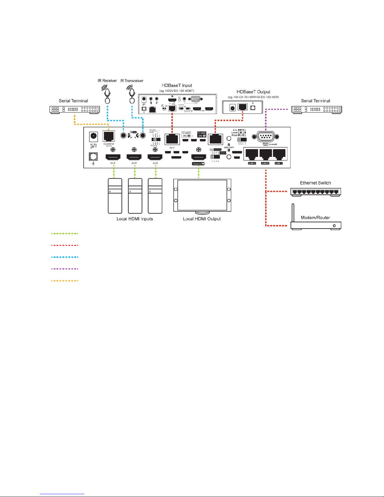
1. Use CATx cables to connect the transmitter to CATx IN R port and connect the receiver to CATx OUT R
2. Use an HDMI cable to connect the source device to the HDMI input port on the Unit. The HDMI input ports
are located on the rear of the Unit.
3. Use an HDMI cable for connection between display and the Output L port on the Unit.
4. Apply the proper power to the Unit; then power on all the attached computers and devices.
NOTE
:
If users encounter no screen display in display connection, you may
1. make sure the device cables are correctly and firmly attached.
2. set your display device’s input source as HDMI.
3. check the PC BIOS configuration about the video output setting.
4. connect your computer to the HDMI Display DIRECTLY to check if the video signal gets through.
5. slide the switches to the correct positions according to your displays.
6. apply EDID Copy to your display (see EDID Setting section).
Page 9
7
Connection Pattern
HDMI
RJ-45 Cable (CAT 5e / 6 / 6a)
IR Cable
VGA
RJ-12 Cable
Page 10
8
VI. LED Indicator
(SW4I-03457-100)
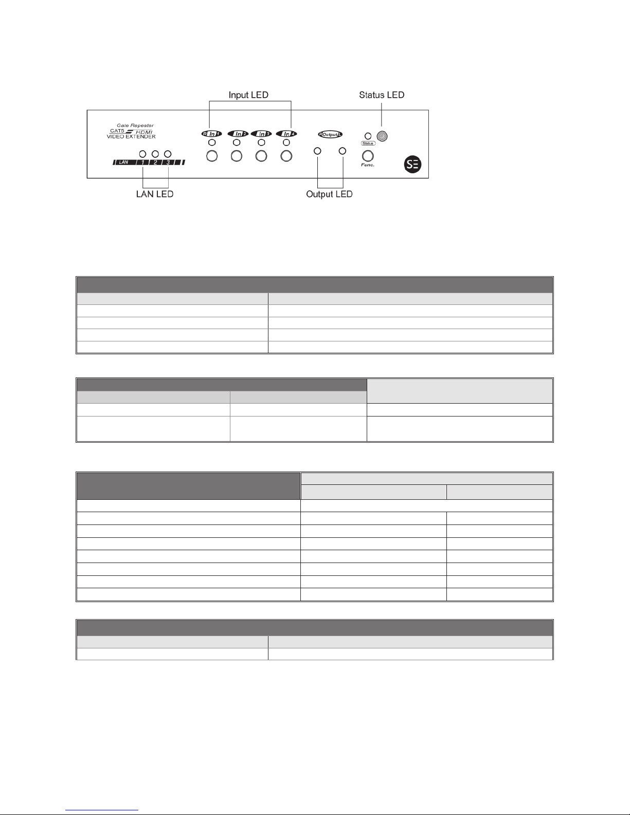
There are four types of LED indicators on the front panel for confirmation. And each LED indicate different
status. Please refer to the following tables.
Status LED Indicator
LED STATUS
Steady blue Power on
Flash blue once per 3 sec. Stand-by mode
Flash green Programming / IR Remote Controller Operating
rewoP ffO off
Input LED Indicator
Input port video source status
The selected port Non selected port
ON (blue)
ydaer tupni ecruos oediV FFO
The LED emits blue and go off
once per 2 sec.
tupni ecruos oediv oN FFO
Output LED Indicator
STATUS
Output device ready Output ON / OFF
yb-dnatS FFO mode
SEY FFO OFF
Flash green once per 2 sec. Local monitor not detected OFF
Flash green twice per 2 sec.
Remote monitor not detected OFF
Emit green and go off once per 2 sec.
Local monitor not detected ON
Emit green and go off twice per 2 sec.
Remote monitor not detected ON
Emit green and go off 3 times per 2 sec.
HDCP unmatched ON
Steady green
NO SEY
LAN LED Indicator
LED STATUS
Flash orange Link OK
Page 11
9
VII. Operation
Push Button Control (-1492X Series)
Users may select 1 from 4 HDMI sources and distribute to the HDMI display via push
button, wireless remote and serial control. A built-in buzzer would generate a high-pitched beep for
a correct push button command and a short-long beep for completing a command. Otherwise, one
low-pitched beep would be generated for an error, and the bad key sequence will not be forwarded
to the unit.
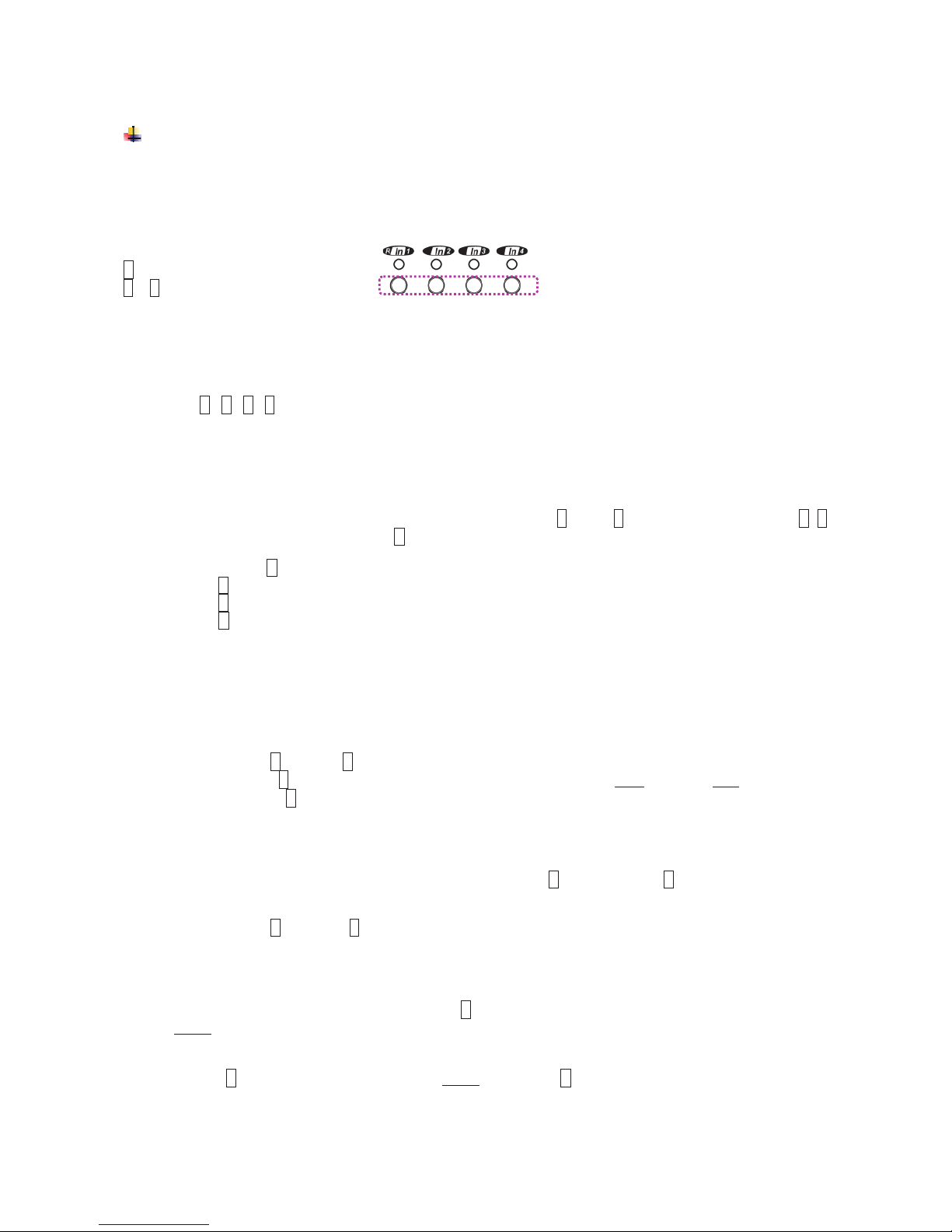
F = Function button
1 ~ 4 = Key1, Key2, Key3, Key4 =
1. A/V Source Selection
For selecting source 1-4, just press the corresponding push button to select the desired source.
Press 1 / 2 / 3 / 4 : Select Source1 / Source 2 / Source 3 / Source 4
2. Turn ON/OFF Remote Output Signal
To turn on or off remote output signal, you may double-click on F, press 1 to enter this setting, press 1~4
to enable/disable signal, and finally press F to exit the setting.
Double- click F
→ Press 1
→ Press 1 (Toggle ON/OFF Remote Output Port)
→ Press F to exit
3. EQ Adjustment
To optimize video quality, users can adjust the video equalization (sharpness) for all video input ports
through push button configuration. Since 8 levels for EQ adjustment are provided, the Remote Output
LED emits blue to indicate level 1-4 is selected, while it emits red to indicate level 5-8 is selected.
Tip: Double-click F → press 4 (enter EQ Adjustment mode)
→press 4 (press 1~8 times based on video quality. 8 levels: Blue-level 1-4; Red-level 5-8)
→press F
4. Turn ON/OFF Beep sound
Users may enable or disable beep sound by double-clicking F and then press 4 to enable or disable
beep sound.
Tip: Double-click F → press 3 (toggle)
5. Stand-by Mode
To have the system switch to stand-by mode, press F button for 3 sec. and release right after the Status LED
flashes green. Then when the Status LED is off, the system is in the stand-by mode. And just follow the same
steps to wake up from stand-by mode.
Tip: press F (3sec.) → Status LED flashes green
→ release F
Page 12
10
6. Factory Default Setting
In case your settings are misbehaving, resetting it to the factory default might be just the way you are looking
for. To return all settings to factory state, you can press and hold the buttons 1 and 2, and then press and
hold 3 and 4. Next, release 3 and 4, and then release 1 and 2.
Tip: Press and hold 1 + 2 → Press and hold 3 + 4
→Release 3 + 4 → Release 1 + 2
7. EDID Setting
In some cases display problems may occur due to incorrect EDID communication between the display
monitor and the unit or inappropriate EDID data programmed by display manufactures. This function allows
the system either to read the necessary EDID information from the unit or to copy EDID from EDID compliant
displays. For more details and functions, please consult the following statements.
7-1. EDID Copy
If the unit is insufficient for EDID of the attached displays, it is suggested to copy EDID from the displays.
Before starting, slide EDID Setting Switch to the desired position.
Copy Local Monitor EDID
Method 1
Step 1. Apply power to the unit.
Step 2. Connect the (EDID compliant) monitor to local output port of the Unit and power on the monitor.
Step 3. Press and hold the button “L EDID COPY” for 3~5 sec. and release the button RIGHT AFTER the
Status LED flashes GREEN.
Result. If the Status LED returns to normal status, indicating that the EDID Copy is completed.
Method 2
NOTE: Before starting, power off the unit and connect monitor to local output port of the Unit
Step 1. Press and hold the button “
L EDID COPY
”
Step 2. Apply power to the unit.
Step 3. Release right after the Status LED flashes GREEN. (3~4 sec.)
Result. If the Status LED returns to normal status, it indicates that the EDID Copy is completed.
Copy Remote Monitor EDID
Method 1
Step 1. Apply power to the unit.
Step 2. Connect the (EDID compliant) receive side monitor to “OUT1” of the Unit and power on the monitor.
Step 3. Press and hold the button “R EDID COPY” for 3~5 sec. and release the button RIGHT AFTER the
Status LED flashes GREEN.
Result. If the Status LED returns to normal status, indicating that the EDID Copy is completed.
Mode Video
Audio
1
Auto Auto (Min.) --
2
Auto Inventory Copy Audio EDID
3
Inventory
Auto (Min.) Copy Video EDID
4
Inventory
Inventory Copy all EDID
Page 13
11
Method 2
NOTE: Before starting, power off the unit and connect receiver side monitor to OUT1 of the Unit
Step 1. Press and hold the button “
R EDID COPY
”
Step 2. Apply power to the unit.
Step 3. Release right after the Status LED flashes GREEN. (3~4 sec.)
Result. If the Status LED returns to normal status, it indicates that the EDID Copy is completed.
Otherwise, the LED flashes RED indicating that:
a. The monitor is not properly connected.
b. The monitor is not powered on.
c. EDID data of the monitor is not applicable.
d. The CATx cable is not well-connected.
7-2. EDID Emulation
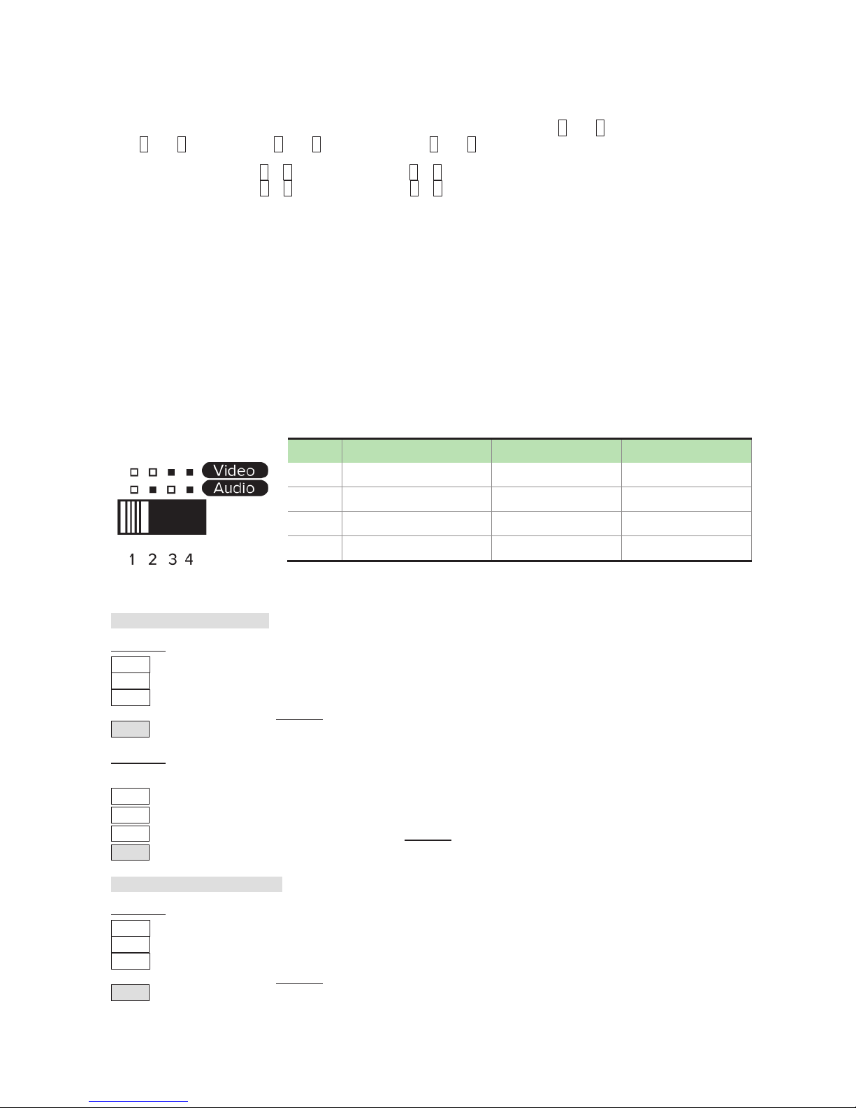
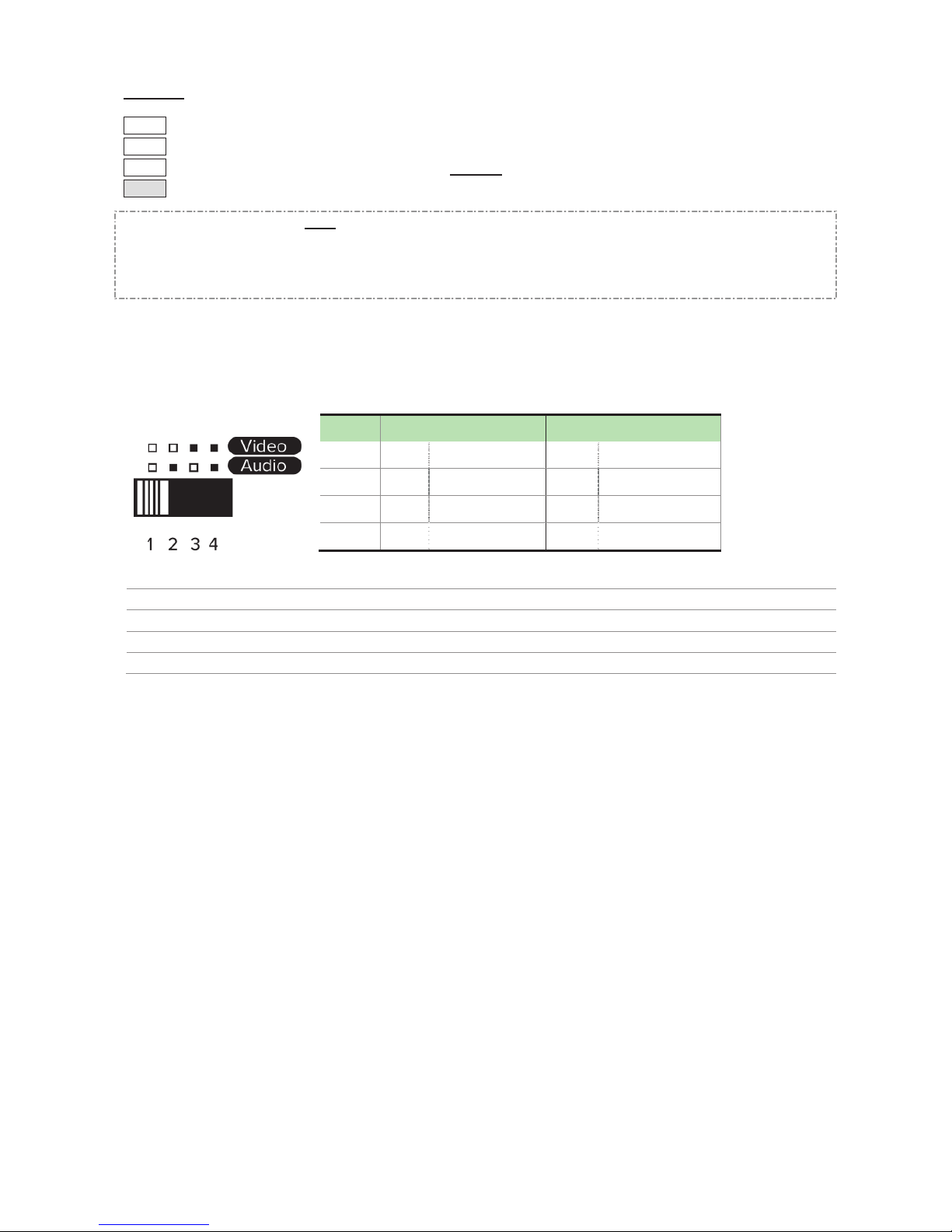
After EDID Copy, you may slide EDID Setting Switch to the desired position and apply the copied EDID to the
display.
Va).
Video Auto Mixing: Automatically optimize all valid video outputs for minimum requirement
Aa).
Audio Auto Mixing: Automatically perform the minimum audio format of all attached displays
Vi).
Video Inventory: After copying Video EDID, use the copied Video EDID to the connected display
Ai).
Audio Inventory: After copying Audio EDID, use the copied Audio EDID to the connected display
Mode Video Audio
1
Va).
Auto
Aa).
Auto (Min.)
2
Va).
Auto
Ai).
Inventory
3
Vi).
Inventory
Aa).
Auto (Min.)
4
Vi).
Inventory
Ai).
Inventory
Page 14
12
IR Remote Control
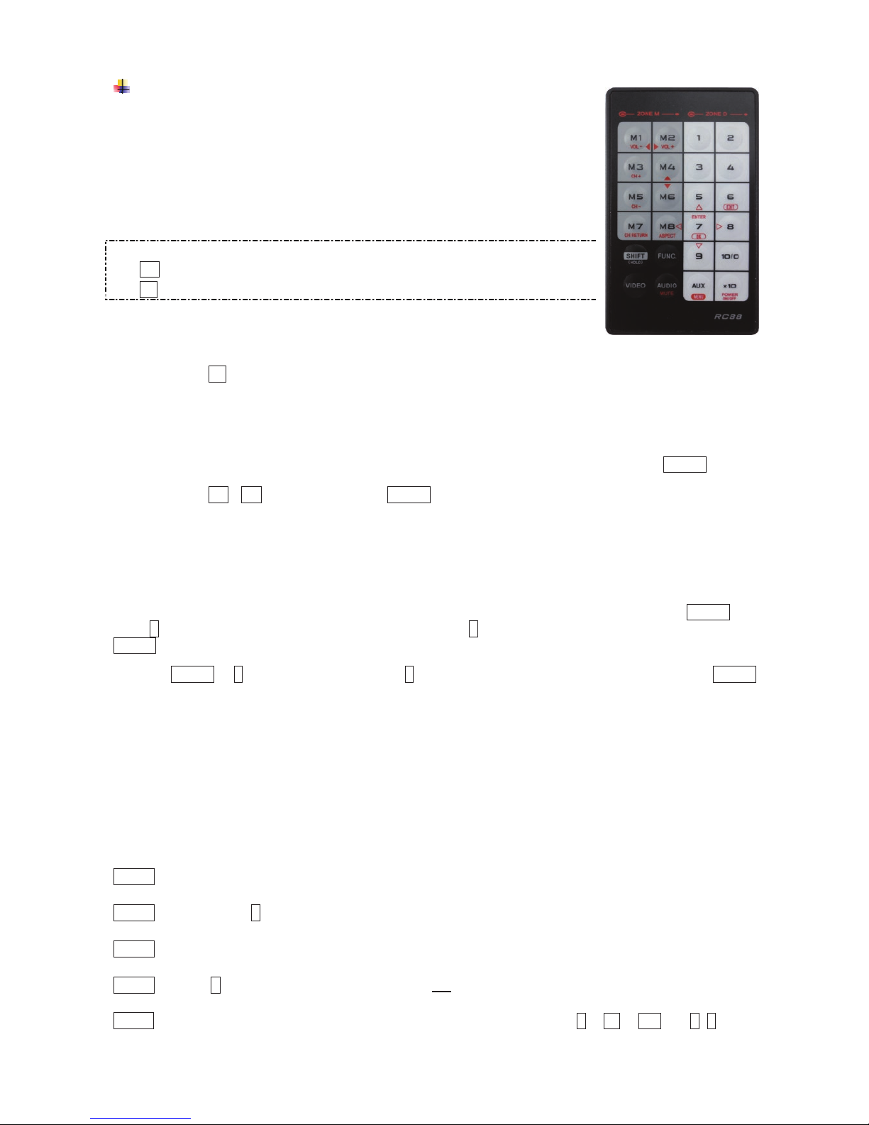
Users can remote control the device within the range of 5 meters. Please
refer to the following for more details.
NOTE: The numeric keys on the left of the controller represents each output on
the rear panel (marked in dark grey area) and while the right stands for the input
displays (marked in light grey area). For other function keys, please refer to the
picture as shown on the right of this page.
Please note the following descriptions:
Mn (output/monitor): buttons M1 ~ M2 on the left side of remote controller
Sn (input/source): buttons 1 ~ 4 on the right side of remote controller
1. A/V Source Selection
For source 1-4, just press the related push button on the right side of the controller.
Tip: Press Sn (right): Select Source-n
2. Turn ON/OFF Remote Output Signal
To turn on or off remote output signal, you may press the output port first, and then press VIDEO.
Tip: Press M1 / M2 (left) and then press VIDEO (toggle)
3. EQ Adjustment
To optimize video quality, users can adjust the video equalization (sharpness) for all video output ports
through push button configuration. Since 4 levels for EQ adjustment are provided, the output LED flashes
blue to indicate level 1-4 is selected and while it flashes red indicating level 5-8 selected. Press VIDEO and
press 4 (right) to enter video adjustment mode. Next, press 4 repeatedly to adjust EQ level. And lastly press
VIDEO to exit the setting.
Tip: VIDEO → 4 (right) (enter this mode) → 4 (right) (press 1~8 times based on video quality) → VIDEO
4. Multi- Unit Application
Up to 16 units can share one remote controller. In order to avoid ambiguities in receiving commands
simultaneously, ID setting for each unit is strongly recommended.
4-1. ID Setting via IR Remote Controller
This function is designed to name the units via push buttons on the front panel and the remote controller.
Please follow the steps below.
Step 1 Power OFF the unit.
Step 2 Press and hold F on the panel of the unit.
Step 3 Power ON the unit.
Step 4 Release F RIGHT AFTER Status LED flashes red.
Step 5 IMMEDIATELY (within a second or two) press one of the numbers from 1 to 10 or x10 and 1~6 on the
Page 15

13
RIGHT side of the IR remote controller to set it as the unit controller ID.
For example, press the number 4 (right). This sets the unit IR remote controller ID as 4. To set the
unit IR remote controller ID as 15, press the number x10 and then 5 (right) on the right side of the
controller.
The idle time out is 10 sec.
NOTE: If the controller ID set-up is needed for more than one unit, follow above Steps 1 to 5 with other units.
To reset ID, follow Step 1 to Step 4 but
Step 5 IMMEDIATELY (within a second or two) press VIDEO of IR remote controller.
4-2. ID Operation via IR Remote Controller
Each unit will respond to the same signal from the IR remote controller whenever the units are powered up. To
prevent the above case, after numbering the unit, users need to press and hold “SHIFT” and then press ID (n)
on the IR remote controller first. Afterwards, this unit will beep once. It means this unit is ready to accept the
oncoming commands via the IR remote controller.
Tip: SHIFT + n ( *n represents the RIGHT numeric keys in light grey area)
NOTE:
Because all units assume their IDs are active after re-powering up, the user needs to press “SHIFT” + ID
again to give commands to a certain unit.
Page 16
14
------------------------ Serial Configuration
The 4K2K HDMI CATx Gate Repeater’s built-in serial interface allows users to control the unit via serial
control. Please follow the installation and operation steps as shown below.
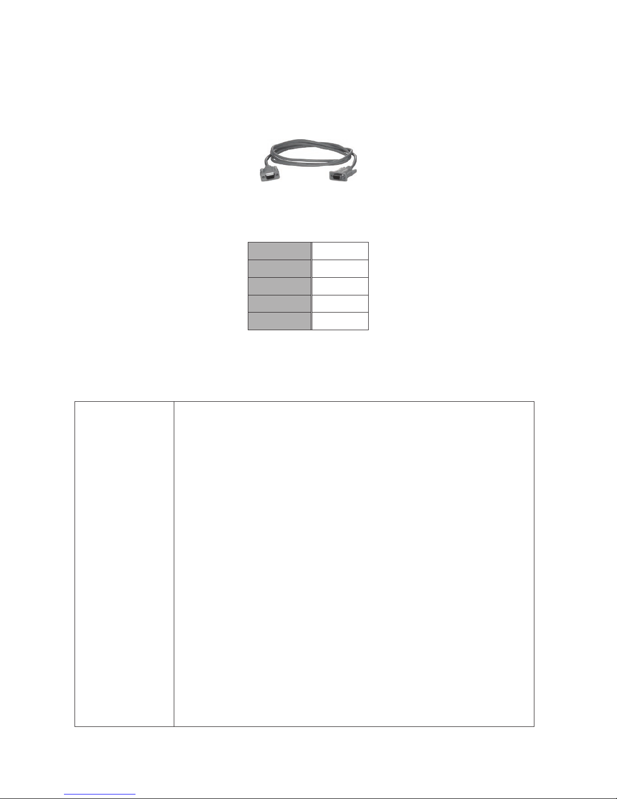
NOTE: Use the following cable for serial connection
Serial Cable (straight type, male-female)
If there’s no serial connector on your computer, you may use USB-to-serial adapter for connection.
The configuration of controller’s serial port is shown as below.
Baud Rate 38,400 bps
Data Bits 8
Parity None
Stop Bits 1
Flow Control None
I. Simple Serial Connection
Connect and power on the Unit, and then set up serial configuration, such as correct baud rate and com port.
After that, you can directly enter the serial commands. All the valid serial commands are listed below.
CE=n,a1,a2 Copy EDID to all input ports
n: Method. a1,a2: Options
1, Default EDID (1080p)
a1,a2 not required
2, Copy EDID from a specified display
a1: output display index (1~2), a2: not required
3, Make 1024 x 768 EDID
4, Make 1280 x 800 EDID
5, Make 1280 x 1024 EDID
6, Make 1360 x 768 EDID
7, Make 1400 x 1050 EDID
8, Make 1440 x 900 EDID
9, Make 1600 x 900 EDID
10, Make 1600 x 1200 EDID
11, Make 1680 x 1050 EDID
12, Make 1920 x 1080 EDID
13, Make 1920 x 1200 EDID
14, Make 1920 x 1440 EDID
15, Make 2048 x 1152 EDID
Page 17

15
16, Make 2560 x 1440 EDID
17, Make 2560 x 1600 EDID
18, Make 3840 x 2160 EDID
19, Make 4096 x 2160 EDID
a1: video options
1, DVI 2, HDMI(2D) 3, HDMI(3D)
a2: audio options
1, LPCM 2 ch 6, Dolby TrueHD 7.1 ch 11, MPEG4 AAC 5.1 ch
2, LPCM 5.1 ch 7, Dolby E-AC3 7.1 ch 12, 5.1 ch combination
3, LPCM 7.1 ch 8, DTS 5.1 ch 13, 7.1 ch combination
4, Dolby AC3 5.1 ch 9, DTS HD 5.1 ch
5, Dolby TrueHD 5.1 ch 10, DTS HD 7.1 ch
AVI=n AV Input Port (n: 1~max)
OLE Enable Local Output (AV)
OLD Disable Local Output (AV)
ORE Enable Remote Output (AV)
ORD Disable Remote Output (AV)
weiV SV settings
tcudorP IP information
EQ=n Set EQ level (n:1~8)
IVG=n Set input VCO Gain level as n (1~8)
OVG=n Set output VCO Gain level as n (1~8)
FACTORY Reset as factory default setting
REBOOT Reboot device
RCID=n Remote Control ID
n: 0 - Reset as null (always respond to IR signals)
1~16 - Valid ID
BEEP=n Beep on / off n: 0 - Off 1 - On
TI=n Set Terminal Interface n: 0 - Human 167 - Machine
LCK=n Lock / Unlock device n: 0 - Unlock 167 - Lock
Page 18

16
II. GUI over Serial
(Note: The real system interface and operation may be further updated. Be sure to operate the system
according to the latest GUI system.)
A. Installing Application
The serial console (PC) with Windows 98/2000/XP/Vista/7 is needed to install the required software. Please follow
the step-by-step instructions as listed below.
All the interfaces shown in this section are for Windows 98 and above. Some of the details may be slightly
different in other versions of Windows.
Install the "AV Console Center” driver (Windows 98 and above)
Insert the CD into the CD/DVD-ROM drive and browse:
There are two ways to install the driver.
a) Manually copy the file "TuApp.exe" to the Windows platform and run it directly.
b) Run "Setup.exe" to automatically install the program on the Windows platform. The "Setup.exe" will
create a shortcut “AV Console Center" on the desktop, and a program group called "AV Console
Center”.
B. Uninstalling Application
The uninstall procedure differs according to the way you installed the program.
a) If you have manually installed the program, you can just manually delete the file "TuApp.exe” from the
Windows platform.
b) If you have installed "Setup.exe" before, you have two ways to uninstall the application. One is to
uninstall "AV Console Center" from the Control Panel in Windows. The other is by clicking the
“Uninstall” icon from the “AV Console Center” program group.
Page 19
17
C. Description & Operation
The Graphical User Interface (GUI) is designed for simple and user-friendly operation. We divide this
application into two parts—Basic Operation and Advanced Operation. For more information, please refer to
the following instructions.
Basic Operation
1. GUI Connection
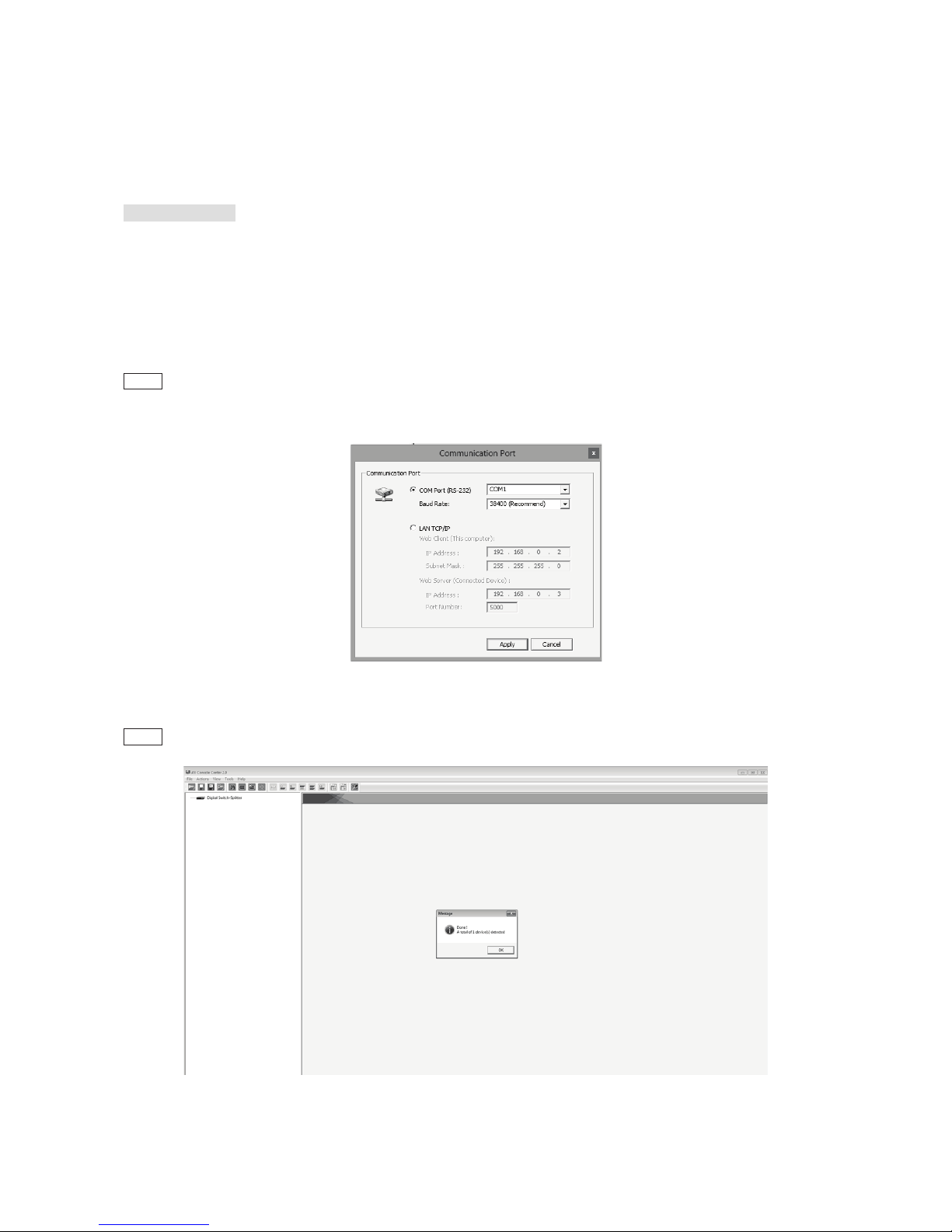
After software installation, connect the DB9 RS-232 serial cable (straight type male-female) to the serial
port of Gate Repeater, and connect the other end to the serial port (COM1, COM2…) of your computer. Next,
open Program files on Windows and then click “AV Console Center” to start GUI operation.
Step 1. Check “COM Port” and choose the proper serial port you connect, such as COM1, and set the Baud Rate as
“38400”.
Step 2.
A dialog box will pop out indicating the device(s) is/are successfully detected.
Page 20
18
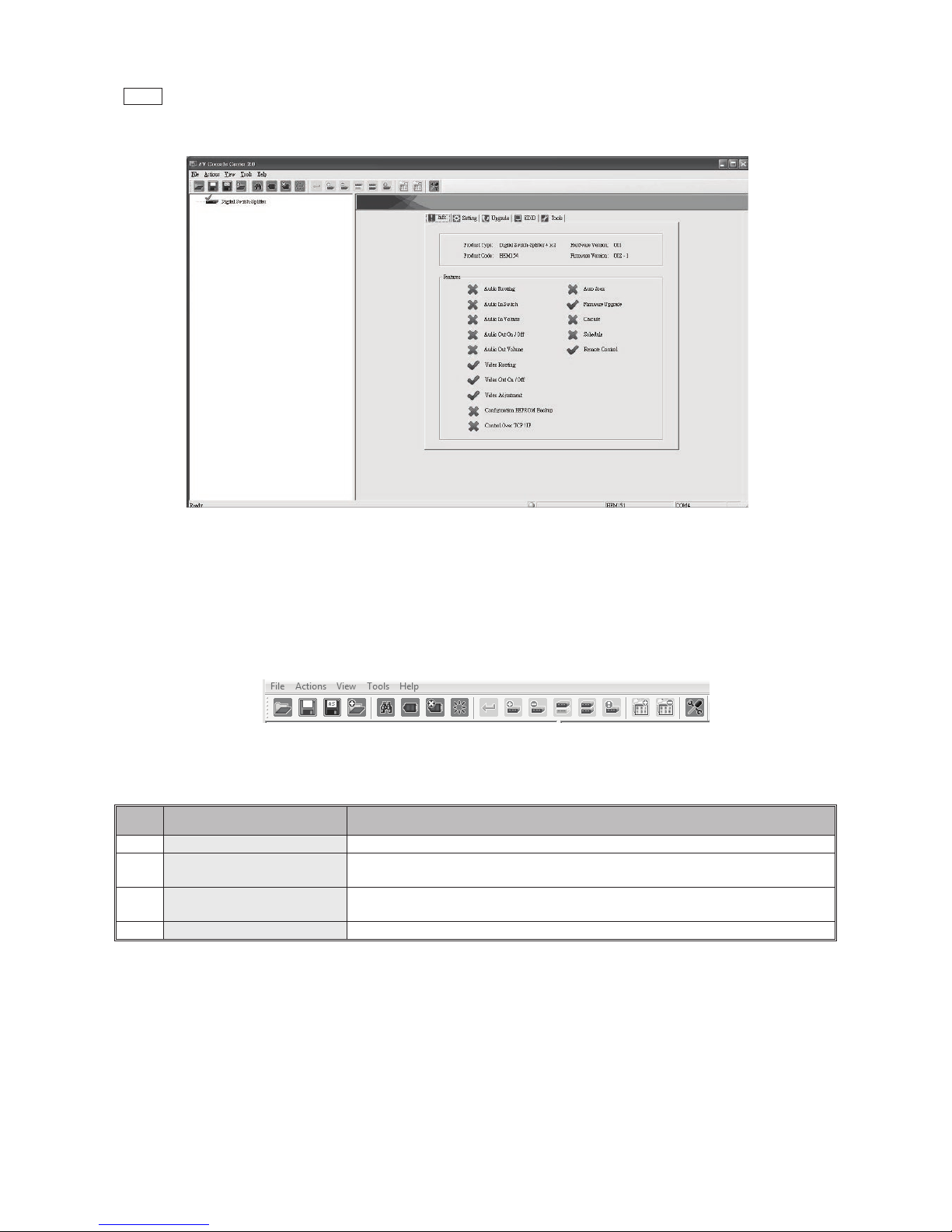
Step 3. Double-click “Digital Switch Splitter” on the left block, and the basic information of the device would be displayed
on the right block (There are other ways to detect the device. Please refer to Toolbar Guidance / Action. )
*Note: Multi-layer cascade is not applicable through GUI.
2. GUI Toolbar Guidance
You can see the toolbar on the upper-left corner. Both top toolbars are identical in functions. For further
information, please refer to the following guidance.
2.1 File: Allow users to open or save topology files. A topology is a usually schematic description of the
arrangement of a network, including its nodes and connecting lines. Saving a topology file is highly
recommended.
2.1
Option Function
1 Open Existing Topology Open pre-stored topology file
2 Save Current Topology
Allow users to save the current topology file in the install location of the
software
3
Save Current Topology
As…
Allow users to save the current topology file in a specific location
4 Exit Exit the system
2.2 Actions: Detect all devices or connect the selected device.
When checking Detect All Devices, it will show the dialog box below to indicate successful detection of
the device(s).
2.3 View: Show or hide the (Icon) Toolbar / Status Bar (on the bottom of the window).
2.4 Tools: Select Environment to set up COM Port and Baud Rate or set up TCP/IP address for the device.
Page 21
19
2.5 Help: Show the software version and copyright information.
3. Function Description
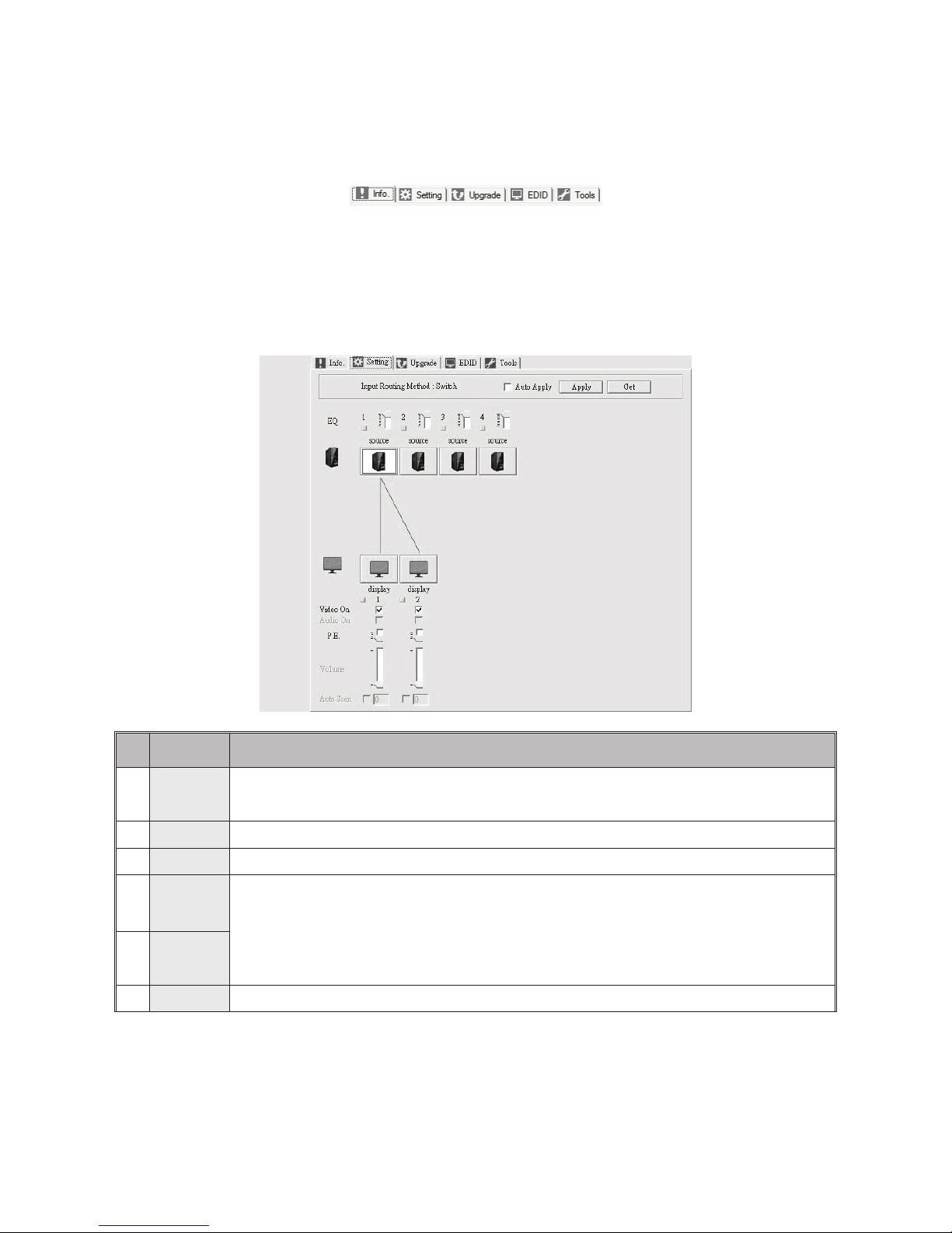
The overall GUI functions would be described in the following, with four sections included: Info, Setting,
EDID, and Tools.
3.1 Info: Show information and features.
3.2 Setting: In this section, users can set up port connection, enable or disable audio/video independently,
etc. By default, the system will automatically apply source 1 routing to all displays as shown below.
3.2 Option Function
1 Auto apply
Automatically apply settings. It is not suggested checking this option for it may result in loading down
the system.
2 Apply To implement the current settings
3 Get Detect and show the current setting status.
4
Source
Icon*
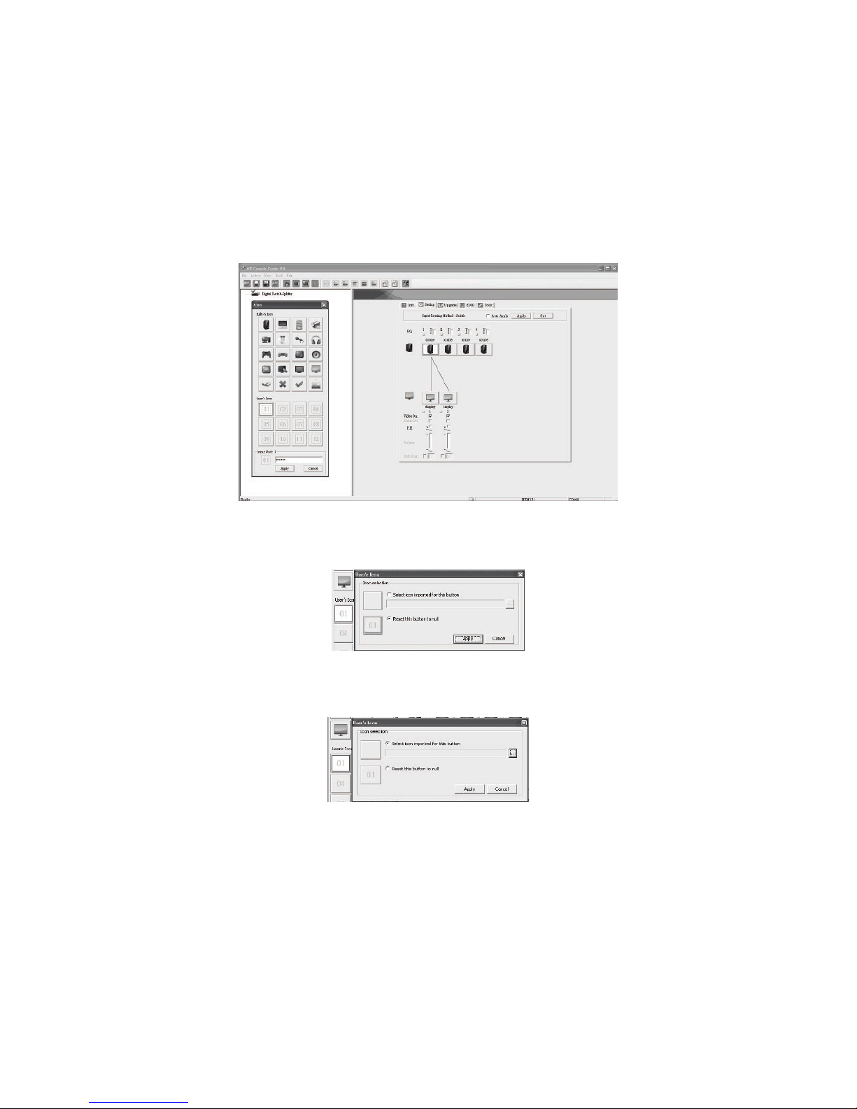
Double-click the icon and there will be a pop-up menu. Users can change the picture (.ico file with
32x32 or 36x36 pix) and give an alias to the source or display.
◆ Linking:
Click one of the source icons and the desired display(s). After that, click “Apply” to
implement the current settings.
5
Display
Icon*
6 Volume Adjust output volume and control the overall level of sound.
Page 22
20
*Changing Source/Display Icon:
Double-click the source/display icon and there will be a pop-up window. Users may change the icon and
name the selected source or display.
1. Name the display/source: click the corresponding icon and key in any name you want.
2. Change the icon
a) Built-in Icons:
The GUI application provides commonly used icons (Built-in Icons) as shown on the upper side of the pop-up
window.
b) User’s Icon - Reset the button to null
As shown on the lower side of the pop-up window, double-click the icon (01-12) and a dialogue box will pop
out. Click this option to set the icon as blank.
c) User’s Icon - Import icon file (.ico) for this button
As shown on the lower side of the pop-up window; double-click the icon (01-12) and a dialogue box will pop
out. You can upload your own icon but the format should be .ico file with 32x32 or 36x36 pix.
Page 23
21
Advanced Operation
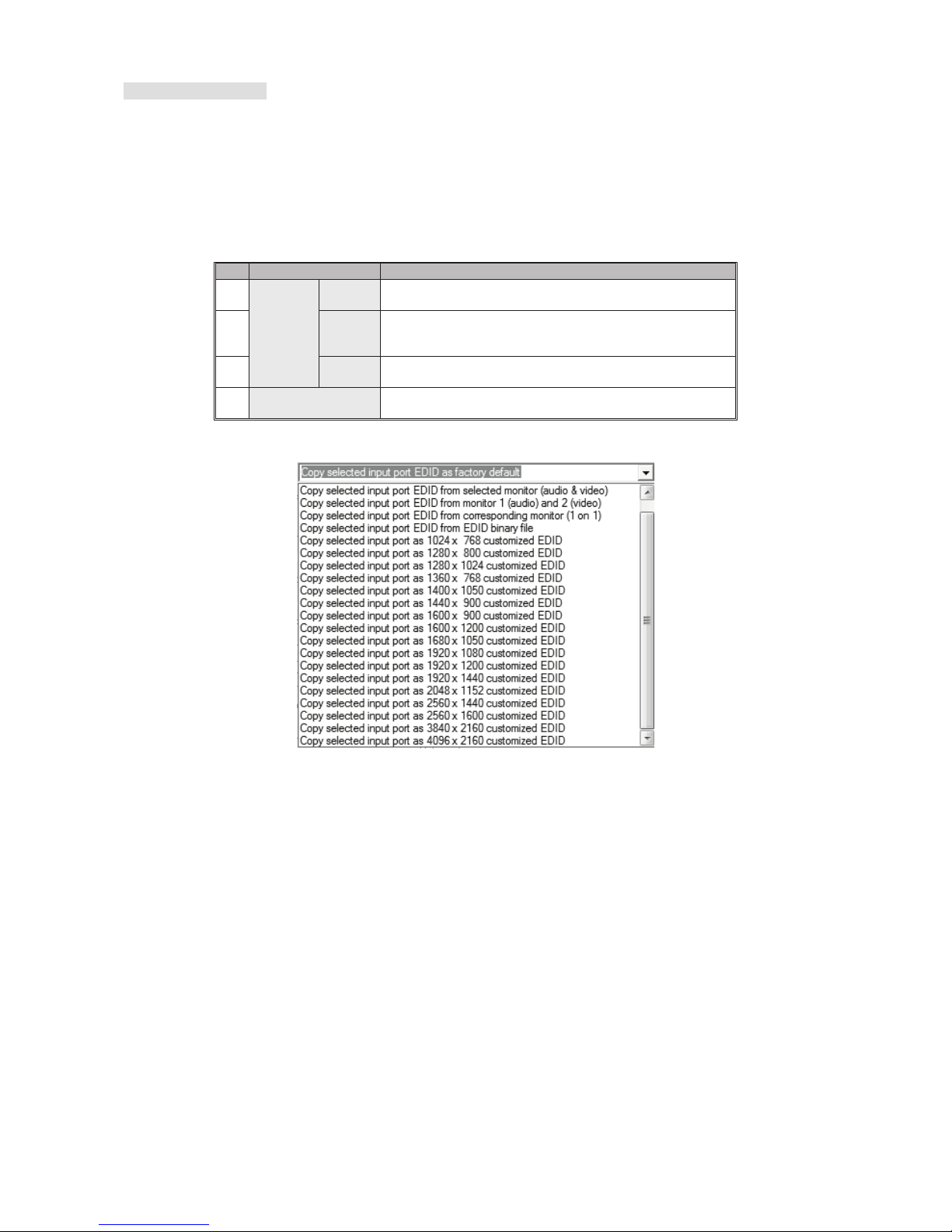
3.5 EDID: Users can not only select the desired ports to copy EDID via multiple methods but also use built-in
EDID for all connected monitors.
Through Inventory EDID, users can either select the desired input ports to copy EDID
via multiple methods, or backup all EDID into inventory for future use. As for Built-In EDID, it provides multiple options for
all connected output ports.
3.5 Option Function
1
Inventory
EDID
Make
EDID
Copy EDID to the selected input port(s).
2
Backup
All
EDID
Click this item to reserve EDID from all input ports and
monitors.
3 Method
Up to 22 methods of EDID copy are provided. See the
diagram below.
4 Built-In EDID
All connected monitors use the selected built-in EDID;
resolution ranging from 1024 x 768 to 4096 x 2160.
Page 24
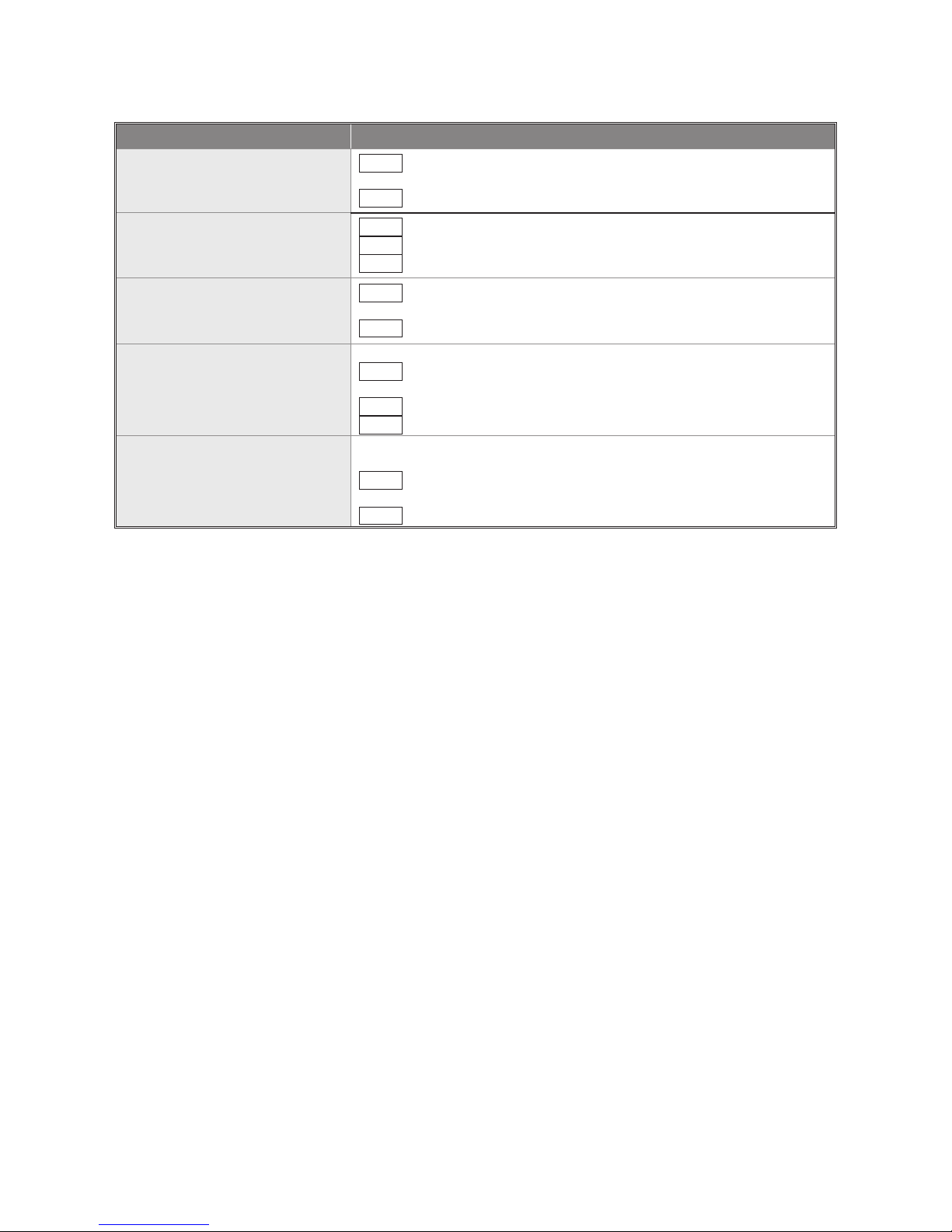
22
Method Operation Steps
Copy selected input port EDID as
factory default
Step 1. Check the desired input port(s) or check All input ports to select
all.
Step 2. Click Make EDID.
Copy selected input port EDID
from selected monitor (audio &
video)
Step 1. Check the desired input port.
Step 2. Select Monitor 1 (next to Method)
Step 3. Click Make EDID.
Copy selected input port EDID
from corresponding monitor (1 on
1)
Step 1. Check the desired input port(s) or check All input ports to select
all.
Step 2. Click Make EDID.
Copy selected input port EDID
from *EDID binary file
*EDID binary file: A file that store EDID information
Step 1. Check the desired input port(s) or check All input ports to select
all.
Step 2. Click Make EDID.
Step 3. Select the desired binary file.
Copy selected input port as *1024
x 768 customized EDID
*Customized EDID: selectable resolution ranging from 1024 x 768 to
2048 x 1152
Step 1. Check the desired input port(s) or check All input ports to select
all.
Step 2. Click Make EDID.
3.6 Tools: Allow users to set up RTC (Real-time clock) and Remote Controller ID. RTC Calibration features
Auto-Calibration and Manual-Calibration.
As for Remote Controller ID, since up to 16 units can share one remote
controller. Therefore, it is designed to name the units for fear of confusion when receiving multiple commands
simultaneously.
Page 25
23
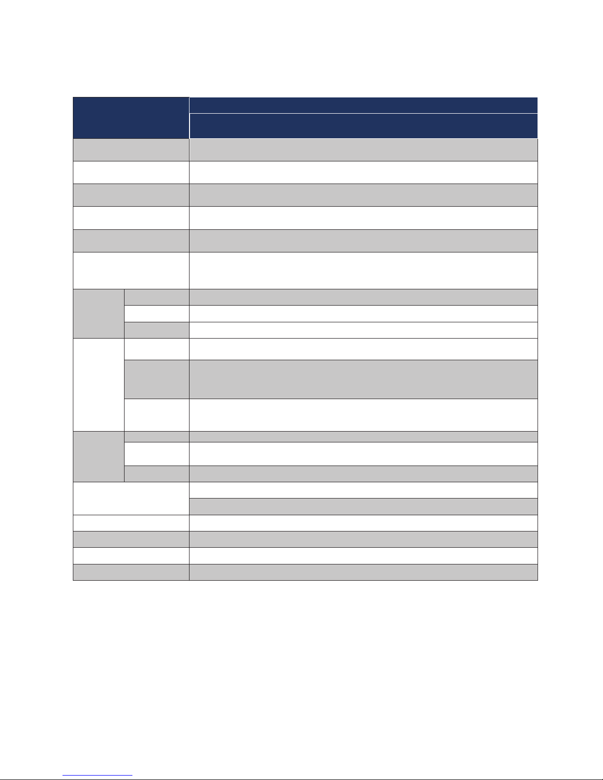
------------------------ Specification
Model
Gate Repeater
SW4I-03457-100
Video Input
(Remote) RJ-45 x 1
(Local) HDMI x 3
Video Output
(Remote) RJ-45 x 1
(Local) HDMI x 1
Ethernet Extension RJ-45 x 3 (10/100 Mbps)
IR Extension x 2 (Transceiver x 1 + Receiver x 1)
Video Resolution (Max.) UHD (3840 x 2160)
Extension Distance 100M
LED
Indicator
Status LED 1
Input LED 4
Output LED 2
Slide
Switch
Audio/Video
EDID Setting
Audio/ Video / Inventory
EGO
(Advanced
Auto-sensing)
Setting
Switch / Auto / Priority-R
Serial
Linking
Setting
Link Mode x 4
Push
Button
Function x 1
Source
Selection
x 4
EDID Copy x 2 (Local x 1 + Remote x 1)
Serial Port
RJ12 x 1 (for control)
DB9-F x 1 (for extension)
Power Supply DC 12V
Enclosure Metal
H x W x D (mm) 34 x 190 x 125
Weight (g) 1020~1070
Page 26

24
Limited Warranty
IN NO EVENT SHALL THE DIRECT VENDOR BE LIABLE FOR DIRECT OR INDIRECT, SPECIAL, INCIDENTIAL OR CONSEQUENTIAL
DAMAGES, LOSS OF PROFIT, LOSS OF BUSINESS, OR FINANCIAL LOSS WHICH MAY BE CAUSED BY THE USE OF THE PRODUCT
EXCEEDS THE PRICE PAID FOR THE PRODUCT.
The direct vendor makes no warranty or representation, expressed or implied with respect to the contents or use of this
documentation, and especially disclaims its quality, performance, merchantability, or fitness for any particular
purpose.
The direct vendor also reserves the right to revise or update the product or documentation without obligation to notify any
user of such revisions or updates. For further information, please contact your direct vendor.
All the brand names and registered trademarks are the property of their respective owners.
© 2016 Serveredge¨ The Serveredge logo, are trademarks of Serveredge, Inc. All other brand and product names are trademarks or registered trademarks of their respective holders. Serveredge makes no warranty of
any kind with regards to the information presented in this document. All information furnished here is for informational purposes only and is subject to change without notice.
Serveredge, Inc. assumes no responsibility for any inaccuracies or errors that may appear in this document.
www.serveredge.com.au
 Loading...