

Page 1
MODEL:
SEI-5
01686-REVC_100715
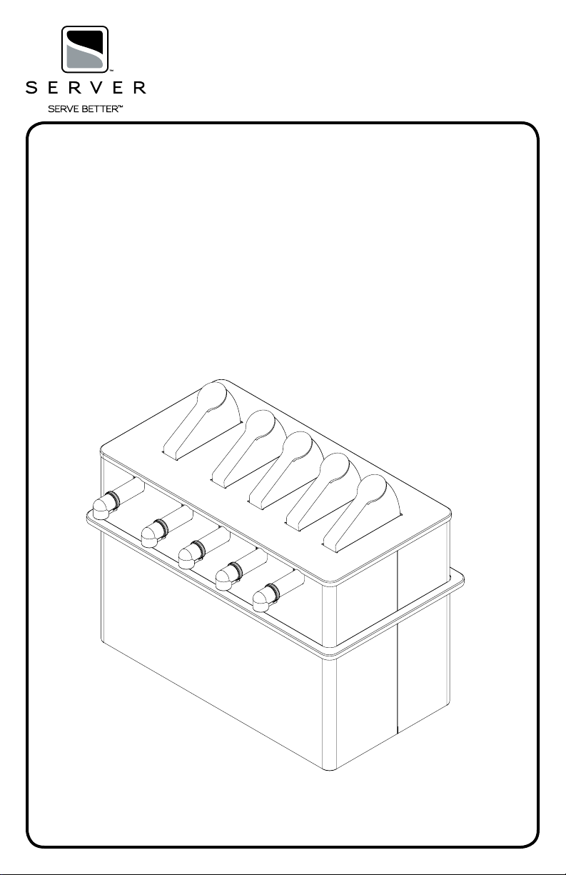
SERVER EXPRESS
TM
QUINTUPLE, INSULATED,
CAPTAIN D
Series 14A
67898
Page 2
SAFETY GUIDELINES
According to food and safety regulations, most foods
must be stored and/or served at certain temperatures
or they could become hazardous. Check with local food
and safety regulators for specic guidelines.
Be aware of the product you are serving and the
temperature the product is required to maintain.
Server Products, Inc. can not be responsible for
the serving of potentially hazardous product.
Server Products Inc. claims no responsibility
for actual serving temperature of product. It is
the responsibility of the user to ensure that any
product is held and served at a safe temperature.
NSF International lists this pump as:
“Not acceptable for dispensing potentially
hazardous foods.”
Stainless steel is one of the best materials for food
serving and storage, but there are many products which
can corrode it. If you notice corrosion beginning on
any stainless steel surface, you may need to change
the cleansing agent, sanitizing agent, or the cleaning
procedures you are using.
• Products containing: acids, alkalines, chlorine,
or salt can corrode stainless steel.
• Sauerkraut and Au Jus sauces corrode stainless
steel. Server Products, Inc. regrets that we can
not honor Warranty claims on stainless steel parts
that have been affected by sauerkraut
or Au Jus.
Insulated Units
• Do not expose insulated shroud or base of unit to
a dishwasher or temperatures over 150°F,
this will damage unit insulation.
Eutectic Ice Packs
• Do not expose eutectic ice packs to a dishwasher
or any extreme heat, this could cause leakage
or explosion of eutectic ice packs. Operating
temperature range for eutectic ice packs is
between -40°F and 175°F.
SPECIFIC INFORMATION
Drop-In Units
Drop-In units can be used either on a counter top surface
or can be dropped into an opening in a counter top.
Recommended Counter Top Opening Size
11 1/2” x 21 7/16”
1 PRE-FREEZE EUTECTIC ICE PACKS.
• Eutectic ice packs must be allowed to freeze for
about 12 hours (or overnight) prior to use.
2 INSTALL EUTECTIC ICE PACKS INTO UNIT.
KEEP OTHER EUTECTIC ICE PACKS IN FREEZER
TO BE READY FOR FUTURE USE.
3 MONITOR TEMPERATURE OF FOOD PRODUCT
IN UNIT, AS NEEDED, AND MAINTAIN A SAFE
REFRIGERATED FOOD PRODUCT TEMPERATURE
OF 40ºF OR BELOW TO PREVENT FOOD
PRODUCT FROM BECOMING HAZARDOUS.
• Remove eutectic ice packs from unit when food
product temperature rises above 40ºF and
replace with other frozen eutectic ice packs
which have been in freezer storage for the
minimum 12 hours required for pre-freeze.
• Eutectic ice packs can keep refrigerated food
product in unit at 40ºF or below for up to 4
hours when placed into an insulated unit and
lled with refrigerated food product.
Page 3
UNIT SET-UP
ALWAYS CLEAN UNIT AND PUMP THOROUGHLY BEFORE
EACH USE. SEE SAFETY GUIDELINES, UNIT TAKEDOWN, PUMP DISASSEMBLY, CLEANING, AND PUMP
ASSEMBLY.
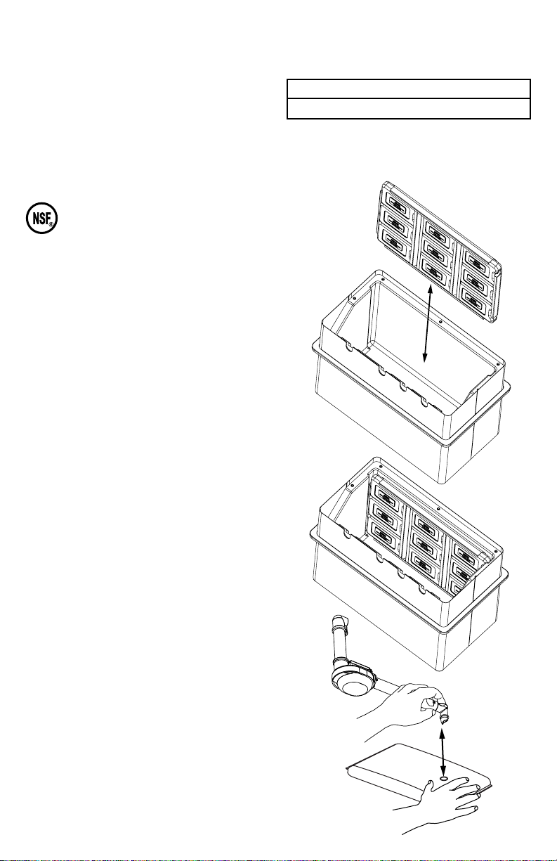
1 INSTALL ICE PACK TRAY INTO UNIT.
2 SET PORTION CONTROL IF NECESSARY.
SEE PORTION CONTROL.
3 ASSEMBLE PUMP. SEE PUMP ASSEMBLY.
4 ATTACH PUMP TO PRODUCT POUCH.
• Place product pouch on a counter top with pouch
tment circle facing upward.
• Remove cap from product pouch.
• Position pump connector directly over center of
pouch tment circle.
• Press pump connector down to pierce through lm
in pouch tment circle.
• Pump connector will be fully engaged into pouch
tment when outer top surface of pouch tment
circle touches pump connector rim.
5 PRIME PUMP.
• Apply light pressure on end of product pouch while
repeatedly compressing pump dome. Continue to
repeat this process until pump is full of product.
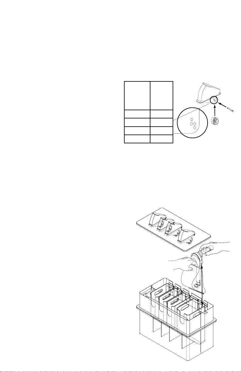
6 INSTALL PUMP AND PRODUCT POUCH
COMBINATION INTO SHROUD.
• Align pump guides into retaining slot on inside wall
of shroud.
7 INSTALL LID.
• Position lid with roller facing near pump dome.
PORTION CONTROL
Portion control is the amount of product which will
dispense from pump with each full push of lever.
The roller, which is attached to the bottom of the lever,
can be adjusted to allow for specic portion control.
How to Set Portion Control
1 REMOVE LID FROM UNIT.
2 REMOVE ROLLER FROM LEVER BY PULLING
HINGE PIN OUT.
3 DETERMINE WHICH PIVOT HOLES IN LEVER WILL
BE USED TO HOLD ROLLER FOR PORTION
DESIRED PER FULL PUSH OF LEVER.
Portion
Desired
(per full
push of
lever)
1 Ounce
3/4 Ounce
1/2 Ounce
1/4 Ounce
4 ALIGN CENTER HOLE OF ROLLER WITH SELECTED
PIVOT HOLES ON LEVER.
5 INSTALL HINGE PIN THROUGH SELECTED PIVOT
HOLE ON ONE SIDE OF LEVER, THROUGH CENTER
HOLE OF ROLLER, AND THROUGH COORDINATING
PIVOT HOLE ON OTHER SIDE OF LEVER.
• Push hinge pin through until it securely snaps into
6 INSTALL LID ONTO UNIT.
place.
Adjust
roller
to pivot
on lever
holes
A
B
C
D
D
B
C
A
UNIT TAKE-DOWN
1 REMOVE LID FROM UNIT.
2 REMOVE PUMP (AND ATTACHED PRODUCT POUCH
IF UNIT HAS ALREADY BEEN IN USE) FROM
SHROUD.
• If unit has already been in use, disconnect pump
from product pouch. Pull pump by connector from
product pouch tment.
3 FLUSH AND RINSE ALL INSIDE AND OUTSIDE
SURFACES OF PUMP THOROUGHLY WITH HOT
WATER.
• Place lower end of pump into container of
hot water and operate pump until all (if any)
remaining product is expelled and only hot water
ows from discharge tube. Then remove pump
from container of water to disassemble.
4 DISASSEMBLE AND CLEAN PUMP.
SEE PUMP DISASSEMBLY AND PUMP CLEANING.
5 REMOVE ICE PACK TRAY FROM UNIT.
6 RE-FREEZE EUTECTIC ICE PACKS.
• Eutectic ice packs must be allowed to freeze for
about 12 hours (or overnight) prior to use.
Page 4

ICE PACK TRAY
Ice Pack & Shroud Assembly (Server Part 67926)
includes 9 rectangular eutectic ice packs, 2 ice pack retainer strips, and 1 ice pack shroud.
DISASSEMBLY
Eutectic ice packs can be removed and replaced
individually from tray if necessary and for cleaning.
Individual Rectangular Ice Pack
(Server Part 94141)
All ice packs can remain installed in tray and
this assembled tray can go into a freezer or into a unit.
1 REMOVE THE ICE PACK THAT IS IN THE
MIDDLE ROW FIRST.
• Flip tray over to access cutout (square hole)
where rst ice pack can be pushed out
and released from tray.
• After releasing rst ice pack, all remaining
ice packs, and two retainer strips, can slide
and release out of tray.
ASSEMBLY
1 INSTALL EUTECTIC ICE PACKS INTO TRAY AS
THREE COLUMNS WITH THREE ROWS. EACH COLUMN IS
DIVIDED AND SECURED BY A RETAINER STRIP.
• First install and slide three eutectic ice packs into tray
with their spout ends facing and positioned under ange
of tray that is on opposite end of tray from cutout.
Flange at opposite end of tray from cutout is wider.
• Install one retainer strip under anges and slide next to
and over eutectic ice packs to complete and secure column.
• Next install and slide three more eutectic ice packs into tray
to make middle column of eutectic ice packs.
• Install other retainer strip under anges and slide next to and over
eutectic ice packs to complete and secure middle column.
• Finally install three more eutectic ice packs into tray to complete tray full of nine
eutectic ice packs. This last column must have eutectic ice packs installed into tray with their
spout ends facing and positioned under last retainer strip installed. Each one of these last three
eutectic ice packs must be installed by individually snapping them into tray to secure them under tray ange.
The last eutectic ice pack to be installed must be installed over the cutout.
REMOVABLE BRACKET
FOR CLEANING
1 REMOVE TWO CAP NUTS TO REMOVE BRACKET.
Page 5

SERVER EXPRESSTM PUMP
ADA, PINCH VALVE,
55 DURO DOME
07604
07399
07491
Part Description
07089 TUBE, PLASTIC, 7”
07381 CONNECTOR, 16MM
07388 HOUSING, PUMP ASSEMBLY, CLR
07399 DOME, PUMP, .281, 55 DURO
07796 FITTING, DISCHARGE, .256-MEDIUM
07491 VALVE, PINCH, TRILOBE
07388
07796
07089
07381
Page 6

PUMP DISASSEMBLY
1 REMOVE CONNECTOR FROM FLEXIBLE PLASTIC
TUBE.
2 ROTATE AND PULL CONNECTOR AWAY FROM
FLEXIBLE PLASTIC TUBE.
3 REMOVE FLEXIBLE PLASTIC TUBE FROM BOTTOM
OF PUMP HOUSING.
4 ROTATE AND PULL FLEXIBLE PLASTIC TUBE AWAY
FROM PUMP HOUSING.
5 REMOVE PUMP DOME FROM PUMP HOUSING.
6 UNHOOK LOOP FROM BOTTOM OF DOME TO
RELEASE DOME FROM PUMP HOUSING.
7 TAKE PINCH VALVE OUT OF PUMP HOUSING.
PUMP ASSEMBLY
ALWAYS CLEAN PUMP THOROUGHLY BEFORE EACH USE.
SEE UNIT TAKE-DOWN, PUMP DISASSEMBLY, PUMP
ASSEMBLY, SAFETY GUIDELINES, AND CLEANING.
1 INSERT PINCH VALVE INTO PUMP HOUSING.
2 INSTALL DOME ONTO PUMP BODY.
• Align valve ap inside dome to be on top of
opening between pump body and pump body
discharge tube.
• Place loop onto pump housing tube to secure
dome.
3 INSTALL FLEXIBLE TUBE ONTO PUMP BODY
SHORT EXTENSION TUBE.
• Use small amount of water as lubricant when
installing exible tube.
• Rotate exible tube onto pump body short
extension tube until projections on pump body
short extension tube align with holes in exible
tube.
• Rotate and position exible tube with connector
on opposite end to be pointing away from pump
body discharge tube.
4 INSTALL CONNECTOR ONTO FLEXIBLE TUBE.
• Use small amount of water as lubricant when
installing connector.
• Rotate connector into exible tube until
projections on connector align and fall into holes
in exible tube.
5 INSTALL DISCHARGE FITTING ONTO PUMP
HOUSING DISCHARGE TUBE.
• Place loop of discharge tting onto peg on end
of discharge tube to secure discharge tting.
PUMP CLEANING
BEFORE FIRST USE AND AFTER USE DAILY,
DISASSEMBLE AND CLEAN PUMP. IT IS IMPORTANT
TO CLEAN, RINSE, SANITIZE, AND DRY THESE PARTS
DAILY AND PROPERLY. FAILURE TO COMPLY WITH
ANY OF THESE INSTRUCTIONS MAY VOID UNIT
WARRANTY:
1 SEE UNIT TAKE DOWN
2 FLUSH AND RINSE ALL INSIDE AND OUTSIDE
SURFACES OF PUMP THOROUGHLY WITH HOT
WATER.
• Place lower end of pump into container of
hot water and operate pump until all (if any)
remaining product is expelled and only hot water
ows from discharge tube. Then remove pump
from container of water to disassemble.
3 DISASSEMBLE PUMP. SEE PUMP DISASSEMBLY.
4 WASH AND SCRUB ALL PARTS WITH HOT WATER
AND DISHWASHING DETERGENT.
• Use supplied brushes to clean all conned areas.
• Do not use abrasive cleansers, scrapers, steel
pads, steel wool, or other cleaning tools that can
scratch surfaces.
• A general purpose, nonabrasive cleaner may be
used on hard to remove food deposits.
• Do not use cleansing agents with high
concentrations of acid, alkaline or chlorine.
• Do not use ammonia to clean pump parts.
Ammonia can damage plastic parts.
5 FULLY RINSE ALL PARTS THOROUGHLY WITH
CLEAR WATER. DRY WITH A CLEAN SOFT CLOTH.
• Fully rinsing and drying all parts can help prevent
corrosion.
6 SANITIZE PARTS FOLLOWING LOCAL
SANITIZATION REQUIREMENTS. ALL PARTS IN
CONTACT WITH FOOD MUST BE SANITIZED.
• Allow parts to fully air dry after sanitization.
• Dishwasher safe.
Page 7

PUMP DISASSEMBLY
PUMP ASSEMBLY
Page 8

CLEANING UNIT
BEFORE FIRST USE AND AFTER USE DAILY,
DISASSEMBLE AND CLEAN PUMP AND UNIT.
STAINLESS STEEL PARTS CAN CORRODE.
IT IS IMPORTANT TO CLEAN, RINSE, SANITIZE, AND
DRY THESE PARTS DAILY AND PROPERLY. FAILURE TO
COMPLY WITH ANY OF THESE INSTRUCTIONS MAY
VOID UNIT WARRANTY.
1 SEE UNIT TAKE DOWN.
2 WASH ALL PARTS WITH DISHWASHING DETERGENT
AND HOT WATER DAILY. RINSE THOROUGHLY AND
DRY WITH A CLEAN SOFT CLOTH.
• A general purpose, nonabrasive cleaner may be
used on hard to remove food deposits.
• A mildly abrasive NYLON or brass brush may be
used to remove any stubborn food or mineral
deposits on interior surfaces of unit.
• Do not use abrasive cleansers, scrapers, steel
pads, steel wool, or other cleaning tools that can
scratch surfaces.
• Do not use cleansing agents with high
concentrations of acid, alkaline or chlorine.
These agents can corrode stainless steel and
plastic.
• Fully rinsing all parts can help prevent corrosion.
• Various elements and minerals, such as chlorides in
tap water, can accumulate on stainless steel parts
and create corrosion.
• To prevent corrosion on any stainless steel parts,
it is important to fully dry with a clean soft cloth
regularly.
3 WIPE EXTERNAL SURFACES OF UNIT DAILY WITH
A CLEAN DAMP CLOTH. DRY WITH A CLEAN SOFT
CLOTH.
• A nontoxic glass cleaner may be used for cleaning
any stainless steel parts and lid.
4 SANITIZE ALL PARTS FOLLOWING LOCAL
SANITIZATION REQUIREMENTS. ALL PARTS IN
CONTACT WITH FOOD MUST BE SANITIZED.
• Allow parts to fully air dry after sanitization.
GENERAL SERVICE, REPAIR,
OR RETURNS
Before sending any item to Server Products for service,
repair, or return, contact Server Products customer
service to request a Return Authorization Number.
Merchandise must be sent to Server Products with this
number.
Merchandise being returned for credit must be in new
and unused condition and not more than 90 days old
and will be subject to a 20% (percent) restocking
charge. Electrical parts (thermostats, heating elements
etc.) are not returnable.
Server Products maintains a fully staffed service
department with highly skilled factory trained personnel.
Service is extremely prompt. Under normal
circumstances, a repaired unit is shipped out the day
after it is received. Labor charges are reasonable.
SERVICE
Contact your dealer or Server Products Inc.
customer service department for the following:
ORDERING REPLACEMENT PARTS
Be prepared to give this information:
• Model Letters/Name/Numbers
• Part Numbers- P/N
• Series Numbers/Letters
• Part Description
This information and other important data is stamped
on the lid or cylinder of pumps or on the bottom or
back side of every unit.
SERVER PRODUCTS
LIMITED WARRANTY
All Server Products equipment is backed by a
two-year limited warranty against defects in materials
and workmanship. For complete warranty information
go to: www.server-products.com
UNIT TROUBLESHOOTING
Possible Problems:
• Pump dispenses little or no product.
• Portion control is not consistent.
Possible Solutions:
• Clean pump.
• Ensure product pouch is not empty.
• Ensure product pouch is installed correctly.
• Ensure roller is properly installed on lever.
• Ensure ap inside pump dome and pinch valve are
properly positioned when assembling pump.
• Ensure pump is installed into retaining slot on
inside front wall of unit.
Server Products Inc.
3601 Pleasant Hill Road
Richfield, WI 53076 USA
262.628.5600
800.558.8722
262.628.5110
spsales@server-products.com
www.server-products.com
 Loading...