

Page 1
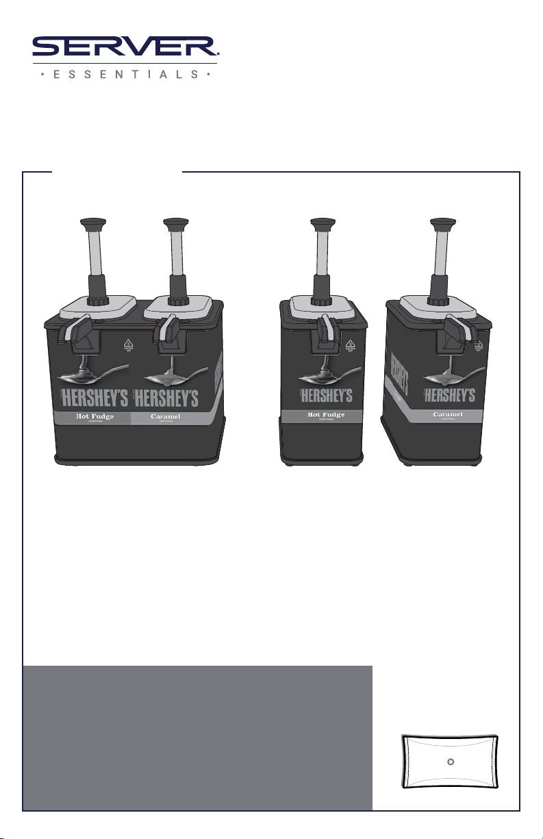
EZ-Topper™
Tall, Twin
MODEL: EZT
HERSHEY'S HOT FUDGE & CARAMEL
84969 COMPLETE
Tall, Single
MODEL: EZT-S
HERSHEY'S HOT FUDGE
84967 COMPLETE
HERSHEY'S CARAMEL
84965 COMPLETE
Thank You
for your purchase. This pouched topping
warmer virtually eliminates product degradation
and waste, so you can reduce food costs while
delivering a superior product.
SIMPLIFY TOPPING MANAGEMENT—GO POUCHED
Used with 48 . oz
pouches with 16mm
center tments.
Page 2
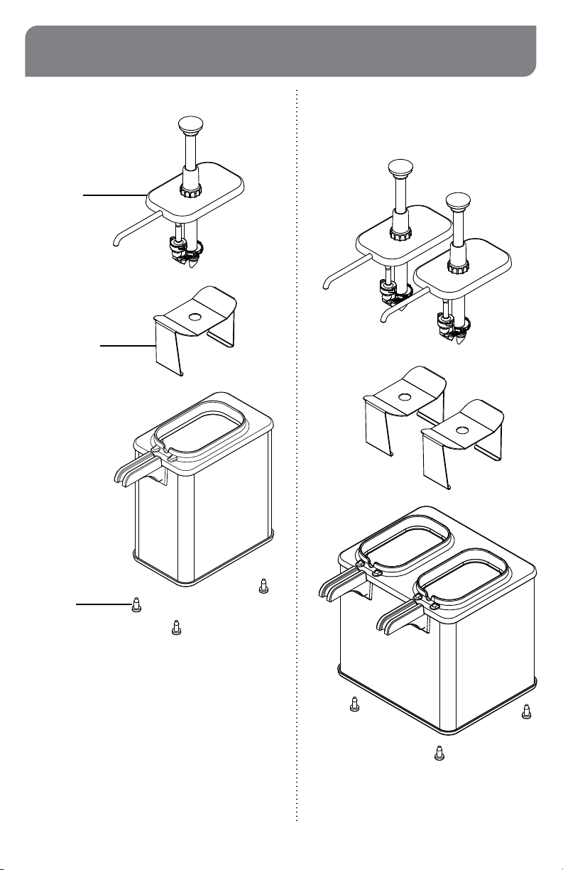
PARTS
UNITS
84965 &
84967
EZ-TOPPER
PUMP
85820
POUCH
SUPPORT
85819
UNIT
84969
FOOT
07429
Page 2
Page 3
SAFETY
According to food and safety regulations, most
foods must be stored and/or served at certain
temperatures or they could become hazardous.
Check with local food and safety regulators for
WARNING-
ELECTRICAL SHOCK COULD OCCUR
This unit must be earthed or grounded.
This requires all three prongs (terminals) on cord
plug to be plugged into power source.
specic guidelines.
Be aware of the product you are serving and the
temperature the product is required to maintain.
Server Products, Inc. can not be responsible for the
serving of potentially hazardous product.
PRE-HEATING PRODUCT POUCHES
• Install pump with pouch.
(See UNIT SETUP, pg. 4.)
• Adjust thermostat to food manufacturer's
recommended serving temperature.
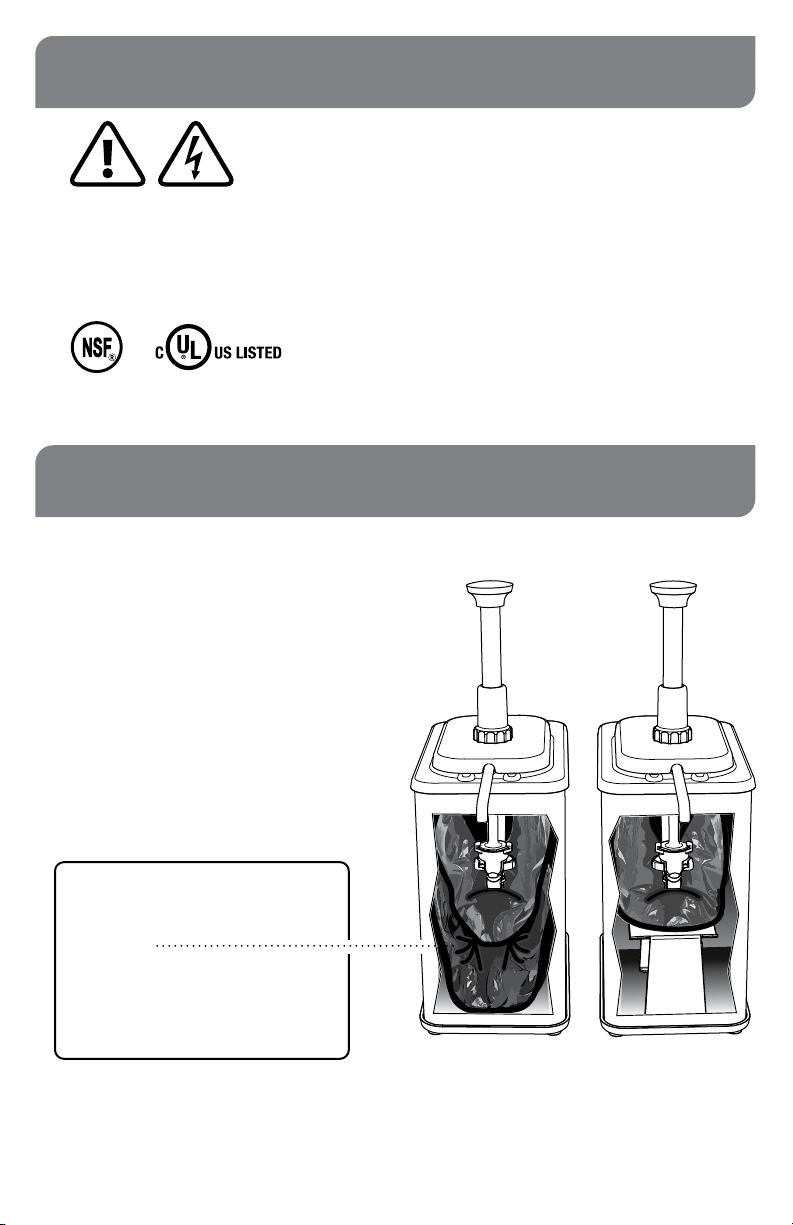
Make change-outs a
cinch.
Place a reserve pouch in the bottom
of the base.
When the primary pouch is emptied,
the reserve pouch is pre-heated
and ready for use.
Cutaway views show:
Reserve Pouch
in base bottom
Pouch Support
in base bottom
Page 3
Page 4
WASH ALL PARTS PROPERLY
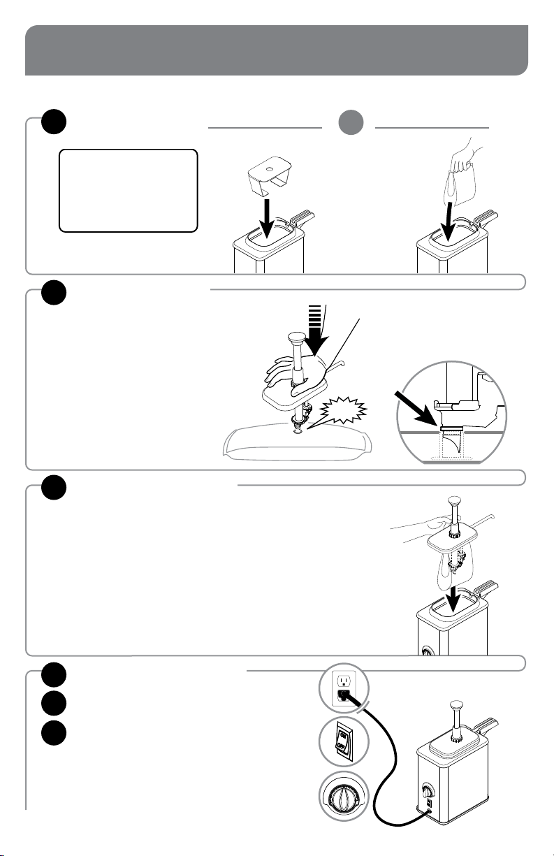
UNIT SETUP
BEFORE EVERY USE.
SEE SEPARATE PUMP MANUAL FOR PUMP SETUP.
See page 6.
INSERT INTO BASE: POUCH SUPPORT RESERVE POUCH
1
IMPORTANT: A pouch
support or reserve pouch
gives the primary pouch the
proper elevation to dispense
all product and heat evenly.
ATTACH PUMP
2
OR
TO PRIMARY POUCH
• Place pouch on countertop with
pouch tment circle facing upward.
• Position pump connector directly
over center of pouch tment.
• Press pump connector down to
pierce through lm in pouch tment.
INSTALL PUMP WITH
3
SNAP
Pump is fully engaged when
top surface of pouch tment
touches pump connector rim.
POUCH INTO BASE
Page 4
PLUG CORD into power source.
4
PRESS SWITCH to the “ON” position.
5
SET THERMOSTAT KNOB
6
to food manufacturer's recommended
serving temperature.
• Dial indicator uses increments of 5º F.
• Thermostat maximum is 210º F/99º C.
Page 5
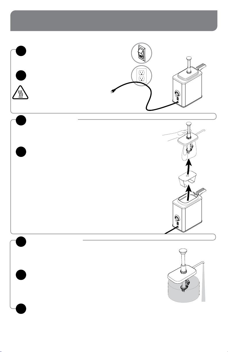
UNIT TAKE-DOWN
PRESS SWITCH to the “OFF” position.
1
UNPLUG CORD
2
CAUTION- HOT
Allow unit to cool before continuing or use
proper care with hot surfaces.
REMOVE PUMP
3
WITH POUCH
REMOVE POUCH SUPPORT OR
4
RESERVE POUCH
DETACH POUCH
5
from bottom of pump.
FLUSH AND RINSE PUMP
6
Thoroughly rinse all inside and outside
surfaces of pump with hot water.
DISASSEMBLE AND CLEAN PUMP.
7
SEE SEPARATE PUMP MANUAL FOR PUMP CLEANING.
Page 5
Page 6
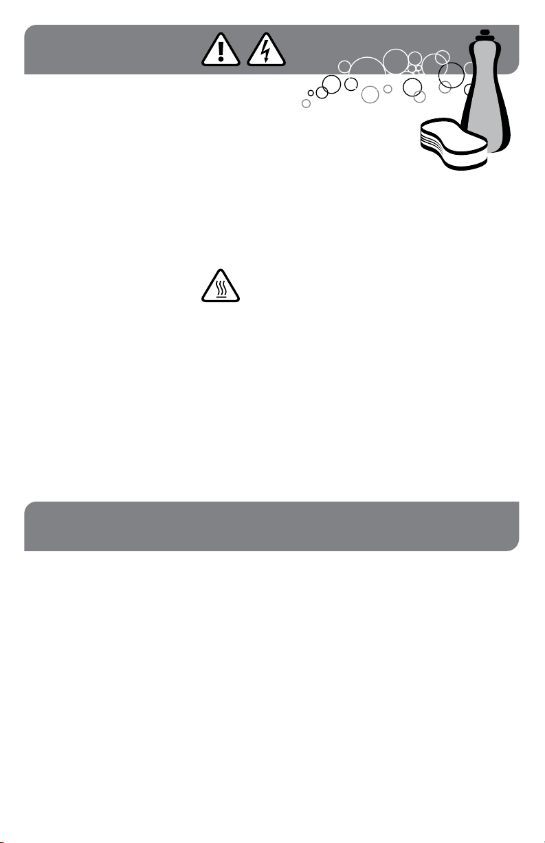
CLEANING
SEE SEPARATE PUMP MANUAL
FOR PUMP INSTRUCTIONS.
WARNING-
ELECTRICAL SHOCK COULD OCCUR
• Electrical components of unit could be
damaged from water exposure or any liquid.
• Never immerse unit into water or any liquid.
• Never use any water jet or pressure sprayer
on unit.
• Ensure unit is “OFF” and unplugged.
CAUTION- HOT
Allow unit to cool before cleaning.
CLEAN EXTERNAL SURFACES
• Wipe daily with a clean damp cloth.
• Dry with a clean soft cloth.
• Glass and surface cleaners approved for use
in food contact areas may be used.
CARE OF STAINLESS STEEL
This warmer and accessories
are constructed of stainless
steel— one of the best materials
for food serving and storage.
If you notice corrosion beginning on any stainless
steel surface, you may need to change the
cleansing agent, sanitizing agent, or the cleaning
procedures you are using.
Page 6
• A mildly abrasive nylon or brass brush may
be used to remove any stubborn food or
mineral deposits on interior surfaces of unit.
• Fully rinsing and drying all parts can help
prevent corrosion. Elements and minerals in
tap water can accumulate on stainless steel
parts and create corrosion.
• Do not use abrasive, caustic or ammonia
based cleansers.
• Do not use products containing acids,
alkalines, chlorine, or salt. These agents can
corrode stainless steel.
• Do not use metal scrapers or cleaning pads
that could scratch surfaces.
Page 7
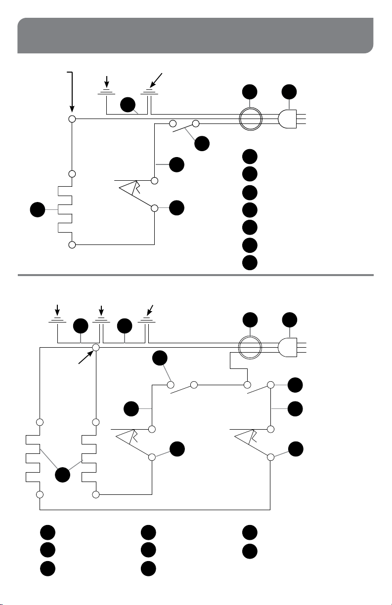
WIRING
120V | USA
TOP (USING
10068 SCREW)
6
GROUND STANDOFF
PIN OTHER VESSEL
ASSEMBLY
7 8
TOP (USING
10068 SCREW)
GROUND STANDOFF
PIN VESSEL ASSEMBLY
7
GROUND STANDOFF
PIN (EITHER ONE)
GROUND STUD
CONTROL PANEL
2
4
2
5
1
GROUND STUD
CONTROL PANEL
3
UNITS 84965, 84967
2
1
3
1
2
3
4
5
6
7
1
GREEN
WHITE
BLACK
Cord Assembly
Bushing/Strain Relief
Snap-In Rocker Switch
6" Wire Assembly, Black
Thermostat
Heating Element
15" Wire Assembly, Green
UNIT 84969
2
12
1
GREEN
WHITE
BLACK
21
3
6
Cord Assembly
1
Bushing/Strain Relief
2
Snap-In Rocker Switch
3
4
2
2
5
1
6" Wire Assembly, Black
4
Thermostat
5
Heating Element
6
1
6" Wire Assembly, Green
7
18" Wire Assembly, Green
8
4
5
Page 7
Page 8
TROUBLESHOOTING
UNIT DOES NOT HEAT?
• Ensure cord is securely plugged in.
• Ensure unit is on.
• Ensure thermostat knob is set correctly.
• Ensure power is available from source.
• Do not allow any of the electrical components
to get wet. Moisture may cause the unit to
trip breaker or GCFI. If moisture is suspected,
discontinue use. Allow unit to fully air dry.
SERVER PRODUCTS
LIMITED WARRANTY
This Server product is backed by a two-year
limited warranty against defects in materials and
workmanship. See Server-Products.com for details.
POUCH DOES NOT EVACUATE
ALL PRODUCT?
• Ensure
that the pouch is properly connected
with pump.
• Ensure that the pouch being dispensed is raised
to proper height. Always use either a pouch
support or a reserve pouch beneath
primary pouch.
GENERAL SERVICE,
REPAIR OR RETURNS
Before sending any item to Server Products for service,
repair, or return, contact Server Products customer
service to request a Return Authorization Number.
Merchandise must be sent to Server Products with this
number. Service is extremely prompt. Typically, units
are repaired and ship out within 48 hours of receipt.
Merchandise being returned for credit must be in new
and unused condition and not more than 90 days
old and will be subject to a 20% restocking charge.
Electrical parts (thermostats, heating elements, etc.)
are not returnable.
Servicing Cord: Specic tools are required for safe and
proper power supply cord removal and installation. If
cord must be replaced, only a representative of the
OEM (original equipment manufacturer) or a qualied
technician may replace cord. Cord must meet code
designation H05 RN-F requirements.
NEED HELP?
Server Products Inc.
3601 Pleasant Hill Road
Richfield, WI 53076 USA
Chat with us!
262.628.5600 | 800.558.8722
Page 8
Please be prepared with your Model, P/N and
Series located on the lid or base of the unit.
Example:
MODEL
XXXX
P/N
#####
Manual #EM_01799_RevC 120122
SERIES
##X ##X
 Loading...