

Page 1

GE Fanuc Automation
Computer Numerical Control Products
DATA SERVER
Operator's Manual
B- 62694EN/03 April 1998
Page 2

Warnings and notices for
GFLE-003
this publication
Warning
In this manual we have tried as much as possible to describe all the various
matters. However, we cannot describe all the matters which must not be done,
or which cannot be done, because there are so many possibilities.
Therefore, matters which are not especially described as possible in this
manual should be regarded as “impossible”.
Notice
This document is based on information available at the time of its publication. While efforts have
been made to be accurate, the information contained herein does not purport to cover all details or
variations in hardware or software, nor to provide every contingency in connection with
installation, operation, or maintenance. Features may be described herein which are not present in
all hardware and software systems. GE Fanuc Automation assumes no obligation of notice to
holders of this document with respect to changes subsequently made.
GE Fanuc Automation makes no representation or warranty, expressed, implied, or statutory with
respect to, and assumes no responsibility for accuracy, completeness, sufficiency, or usefulness of
the information contained herein. No warranties of merchantability or fitness for purpose shall
apply.
The following are Registered Trademarks of GE Fanuc Automation
CIMPLICITY® Genius®
The following are Trademarks of GE Fanuc Automation
Alarm Master
CIMSTAR
Field Control
Genet
Helpmate
LogicMaster
Modelmaster
PowerMotion
ProLoop
PROMACRO
Series Five
Series 90
Series One
Series Six
Series Three
VuMaster
Workmaster
© Copyright 1998 FANUC Ltd.
Authorized Reproduction GE Fanuc Automation Europe S.A.
All Rights Reserved
No part of this manual may be reproduced in any form.
All specifications and designs are subject to change without notice.
Page 3

• No part of this manual may be reproduced in any form.
• All specifications and designs are subject to change without notice.
The products in this manual are controlled based on Japan’s “Foreign Exchange and
Foreign Trade Law”. The export from Japan may be subject to an export license by the
government of Japan.
Further, re-export to another country may be subject to the license of the government of
the country from where the product is re-exported. Furthermore, the product may also be
controlled by re-export regulations of the United States government.
Should you wish to export or re-export these products, please contact FANUC for advice.
In this manual we have tried as much as possible to describe all the various matters.
However, we cannot describe all the matters which must not be done, or which cannot be
done, because there are so many possibilities.
Therefore, matters which are not especially described as possible in this manual should be
regarded as ”impossible”.
This manual contains the program names or device names of other companies, some of
which are registered trademarks of respective owners. However, these names are not
followed by ® or ™ in the main body.
Page 4

Page 5
B62694EN/03
SAFETY PRECAUTIONS
SAFETY PRECAUTIONS
This section describes the safety precautions relating to the use of CNC units, to
ensure safe operation of machines fitted with FANUC CNC units.
section carefully before attempting to use any function described in this manual.
Users should also read the relevant descriptions in the Operator’s Manual to
become fully familiar with the functions to be used.
Contents
Read this
1. WARNING, CAUTION, AND NOTE
2. GENERAL WARNINGS AND NOTES.
.............................
........................... s_3
s_2
s-l
Page 6
SAFETY PRECAUTIONS
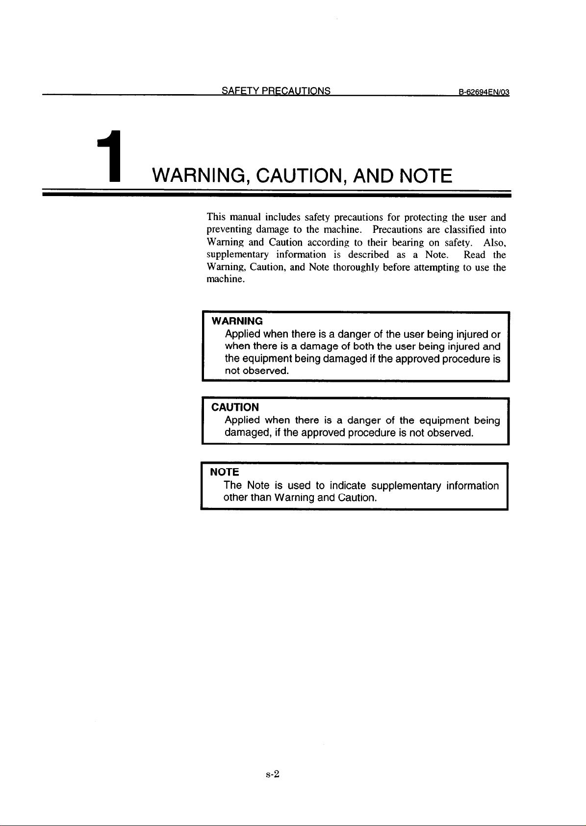
1 WARNING, CAUTION, AND NOTE
This manual includes safety precautions for protecting the user and
preventing damage to the machine. Precautions are classified into
Warning and Caution according to their bearing on safety. Also,
supplementary information is described as a Note. Read the
Warning, Caution, and Note thoroughly before attempting to use the
machine.
WARNING
Applied when there is a danger of the user being injured or
when there is a damage of both the user being injured and
the equipment being damaged if the approved procedure is
not observed.
B-62694ENlOQ
CAUTION
Applied when there is a danger of the equipment being
damaged, if the approved procedure is not observed.
NOTE
The Note is used to indicate supplementary information
other than Warning and Caution.
s-2
Page 7
B62694EN103
SAFETY PRECAUTIONS
2
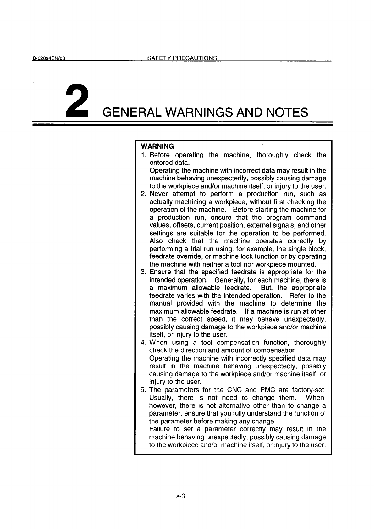
GENERAL WARNINGS AND NOTES
WARNING
1. Before operating the machine, thoroughly check the
entered data.
Operating the machine with incorrect data may result in the
machine behaving unexpectedly, possibly causing damage
to the workpiece and/or machine itself, or injury to the user.
2. Never attempt to perform a production run, such as
actually machining a workpiece, without first checking the
operation of the machine.
a production run, ensure that the program command
values, offsets, current position, external signals, and other
settings are suitable for the operation to be performed.
Also check that the machine operates correctly by
performing a trial run using, for example, the single block,
feedrate override, or machine lock function or by operating
the machine with neither a tool nor workpiece mounted.
3. Ensure that the specified feedrate is appropriate for the
intended operation.
a maximum allowable feedrate.
feedrate varies with the intended operation.
manual provided with the machine to determine the
maximum allowable feedrate.
than the correct speed, it may behave unexpectedly,
possibly causing damage to the workpiece and/or machine
itself, or injury to the user.
4. When using a tool compensation function, thoroughly
check the direction and amount of compensation.
Operating the machine with incorrectly specified data may
result in the machine behaving unexpectedly, possibly
causing damage to the workpiece and/or machine itself, or
injury to the user.
5. The parameters for the CNC and PMC are factory-set.
Usually, there is not need to change them. When,
however, there is not alternative other than to change a
parameter, ensure that you fully understand the function of
the parameter before making any change.
Failure to set a parameter correctly may result in the
machine behaving unexpectedly, possibly causing damage
to the workpiece and/or machine itself, or injury to the user.
Before starting the machine for
Generally, for each machine, there is
But, the appropriate
Refer to the
If a machine is run at other
s-3
Page 8
SAFETY PRECAUTIONS B62694FNl03
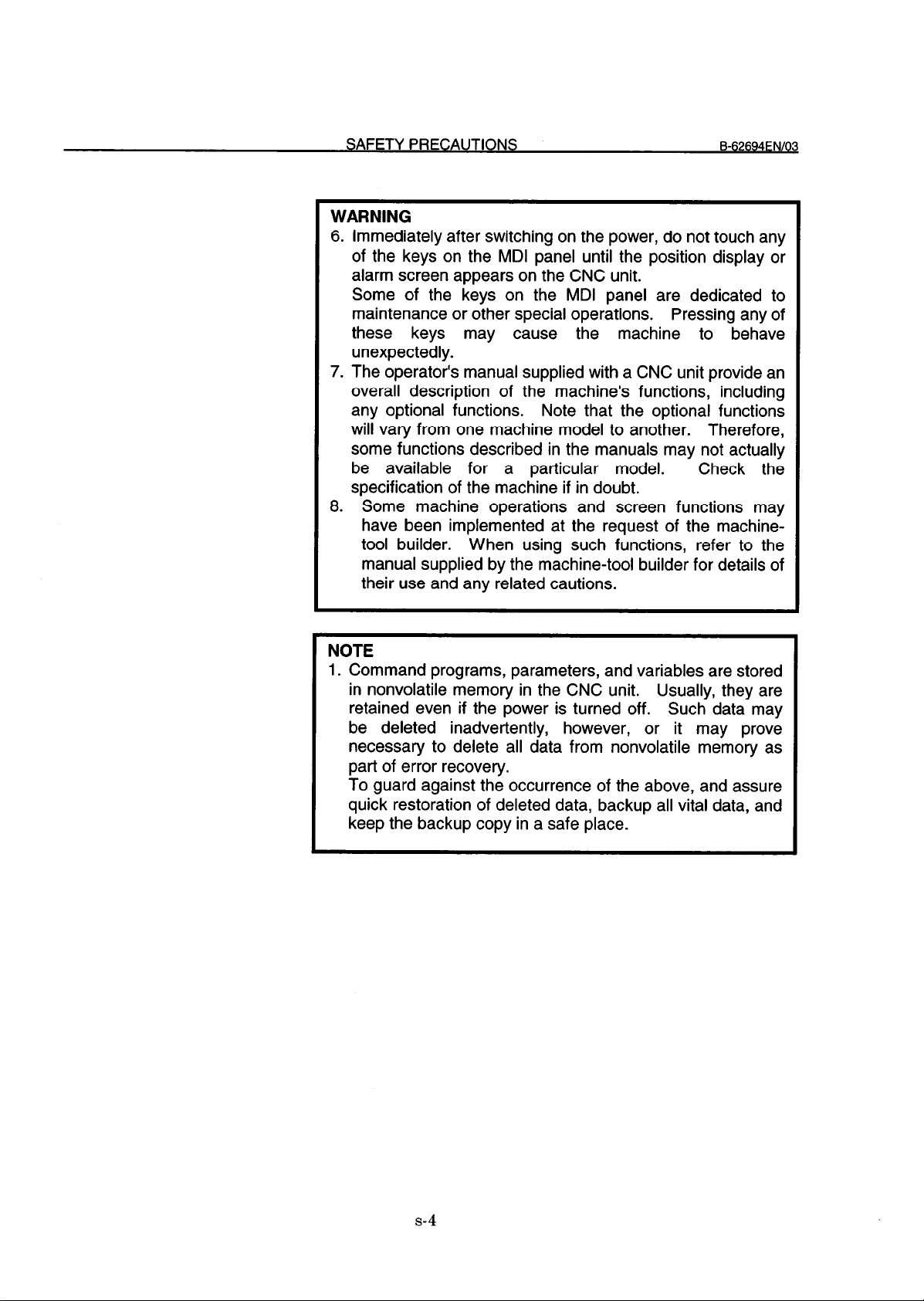
WARNING
6.
Immediately after switching on the power, do not touch any
of the keys on the MDI panel until the position display or
alarm screen appears on the CNC unit.
Some of the keys on the MDI panel are dedicated to
maintenance or other special operations.
Pressing any of
these keys may cause the machine to behave
unexpectedly.
7.
The operator’s manual supplied with a CNC unit provide an
overall description of the machine’s functions, including
any optional functions.
will vary from one machine model to another.
Note that the optional functions
Therefore,
some functions described in the manuals may not actually
be available for a particular model.
Check the
specification of the machine if in doubt.
8.
Some machine operations and screen functions may
have been implemented at the request of the machinetool builder. When using such functions, refer to the
manual supplied by the machine-tool builder for details of
their use and any related cautions.
NOTE
1. Command programs, parameters, and variables are stored
in nonvolatile memory in the CNC unit. Usually, they are
retained even if the power is turned off. Such data may
be deleted inadvertently, however, or it may prove
necessary to delete all data from nonvolatile memory as
part of error recovery.
To guard against the occurrence of the above, and assure
quick restoration of deleted data, backup all vital data, and
keep the backup copy in a safe place.
s-4
Page 9
P-@‘-4FN/O3
SAFETY PRECAUTIONS . . . . . . . . . . . . . . . . . . . . . . . . . . . . . . . . . . . . . . . . . . s-1
Table of Contents
I. GENERAL
1. OUTLINE
. . . . . . . . . . . . . . . . . . . . . . . . . . . . . . . . . . . . . . . . . . . . . . . . . . . . . . . . . . . . . . . . . . . . . . . . . . . . . . . . . . . . . . . . . . . . . . . . . . . . . . . . . . . . . . . . . . . . . . . . ................
II. CONNECTION
1. FOR Series 16/18-B/C, Series 15-B
CONSTRUCTION
1.1
1.2 INSTALLATION..
1.2.1
1.2.2
1.2.3
GENERAL CONNECTION DIAGRAM
1.3
Environmental Requirements
Cable Lead-in Diagram
Connector Disposition of Data Server Board
2. FOR Series 16i/l8i-A
2.1
2.2
2.3
CONSTRUCTION
INSTALLATION
2.2.1
2.2.2
2.2.3
GENERAL CONNECTION DIAGRAM
2.3.1
2.3.2
Environmental Requirements
Cable Lead-in Diagram..
Connector Disposition of Data Server Board
General Connection Diagram
Connection of HDD Unit
.................................................................................................................................
............................................................................................................. . ..................
. . . . . . . . . . . . . . . . . . . . . . . . . . . . . . . . . . . . . . . . . . . . . . . . . . . . . . . . . . . . . . . . . . . . . . . . . . . . . . . . . . . . . . . . . . . . . . . . . . . . . . . . . . . . . . . . . . . .
.................................................................................................................................
...................................................................................................................................
3
.............................................................................................. 11
12
.13
.....................................................................................................
..............................................................................................................
.............................................................................
...............................................................................................
13
14
15
16
17
18
19
.....................................................................................................
...........................................................................................................
.............................................................................
...............................................................................................
.....................................................................................................
...........................................................................................................
19
.20
21
23
23
24
3. CONNECTION WITH NETWORK
3.1 CONNECTION WITH THE ETHERNET
3.2
3.3
3.4
AUI(Attachment Unit Interface) PIN CONFIGURATION..
CONNECTION OF THE TRANSCEIVER CABLE
SHIELDING EARTH OF THE TRANSCEIVER CABLE
.............................................................................................
............................................................................................
.................................................................
.............................................................................
...................................................................
III. MAINTENANCE
1. FOR Series 16/l 8-B/C, Series 15-B ..............................................................................................
SYSTEM BLOCK DIAGRAM ..... ..........................................................................................................
1.1
PARTS LAYOUT.. ................................................................................................................................
1.2
c-l
26
27
.28
29
30
.
35
36
.
37
Page 10
TABLE OF CONTENTS
B-62694EN/OIj
1.3 LIGHTING OF LEDS AND MEANING
1.4
HOW TO EXCHANGE A FUSE
2. FOR Series 16i/l%-A
2.1 SYSTEM BLOCK DIAGRAM
2.2
2.3
PARTS
LIGHTING OF LED AND MEANING
2.3.1
2.3.2 In Case of Latter Edition than 02B
. . . . . . . . . . . . . . . . . . . . . . . . . . . . . . . . . . . . . . . . . . . . . . . . . . . . . . . . . . . . . . . . . . . . . . . . . . . . . . . . . . . . . . . . . . . . . . . . . . . . . . . . . . . . . . . . . . . .
LAYOUT . . . . . . . . . . . . . . . . . . . . . . . . . . . . . . . . . . . . . . . . . . . . . . . . . . . . . . . . . . . . . . . . . . . . . . . . . . . . . . . . . . . . . . . . . . . . . . . . . . . . . . . . . . . . . . . . . . . . . . . . .......... 43
In Case of Edition 01 A
IV. OPERATION
1. FOR Series 16/18-B/C, Series
1.1
OUTLINE ..............................................................................................................................................
1.1.1
1.2
1.2.1 Description of Each Data
Notice when You
SETTING SCREEN ...............................................................................................................................
.............................................................................................
..........................................................................................................
.38
.40
41
. . . . . . . . . . . . . . . . . . . . . . . . . . . . . . . . . . . . . . . . . . . . . . . . . . . . . . . . . . . . . . . . . . . . . . . . . . . . . . . . . . . . . . . . . . . . . . . . . . . . . . . . . . . . . . 42
. . . . . . . . . . . . . . . . . . . . . . . . . . . . . . . . . . . . . . . . . . . . . . . . . . . . . . . . . . . . . . . . . . . . . . . . . . . . . . . . . . . . . . . . . . . . . . . . . 45
. . . . . . . . . . . . . . . . . . . . . . . . . . . . . . . . . . . . . . . . . . . . . . . . . . . . . . . . . . . . . . . . . . . . . . . . . . . . . . . . . . . . . . . . . . . . . . . . . . . . . . . . . . . . . . 46
. . . . . . . . . . . . . . . . . . . . . . . . . . . . . . . . . . . . . . . . . . . . . . . . . . . . . . . . . . . . . . . . . . . . . . . . . . . . . . . . . . . . . . . . . . . . 48
1.6i/18i-A.. ..................................................................................... 53
54
Use for the First Time
..........................................................................................................
..................................................................................
.55
56
.58
1.2.2
1.2.3 How to Input Small Letters
1.2.4 How to Set a Host Directory
1.2.5 How to Save Modified
1.3 NC PROGRAM MANAGEMENT FUNCTION
1.3.1 Displaying the Table of NC Programs
1.3.2 Searching a NC
1.3.3 Deleting NC Programs ...............................................................................................................
1.3.4 Getting a NC Program
1.3.5 Putting a NC Program
1.3.6 List-Getting NC
1.3.7
1.3.8
1.3.9 A Format of List-File
1.3.10
1.4
CALLING
1.5
REGISTERING A NC PROGRAM
1.6 OUTPUTTING A NC PROGRAM
How to Input Data..
List-Putting NC
List-Deleting NC
A Format of NC
A SUBPROGRAM WITH Ml 98
...................................................................................................................
........................................................................................................
Data
Program
Programs
Programs..
Program..
...........................................................................................................
..............................................................................................................
...............................................................................................................
........................................................................................................
.......................................................................................................
Programs..
................................................................................................................
........................................................................................................
.....................................................................................................
......................................................................................................
..................................................................................
......................................................................................
.....................................................................................................
.......................................................................................
......................................................................................................
......................................................................................................
.60
62
.63
.65
.66
.67
.71
72
.74
.76
.79
.82
.85
.87
.88
.89
.91
.92
1.7 DNC OPERATION ................................................................................................................................
1.8
MAINTENANCE
OF
THE
BUILT-IN HARD
c-2
DISK
..........................................................................
93
.94
Page 11
Page 12
Page 13

Page 14
1
About this manual SAFETY PRECAUTIONS
OUTLINE
This manual consists of the following parts:
Notes for reading this manual is described.
I. GENERAL
Chapter organization, applicable models, and related
manuals are described.
II. CONNECTION
The method of connecting each device and notes for
connection are described.
Ill. MAINTENANCE
The drawing number of the Data Server, meaning of the
LEDs, and the error messages are described.
IV. OPERATION
How to operate the Data Server functions are described.
APPENDIX
The error messages and technical terms, etc. are described.
-3-
Page 15
1. OUTLINE
GENERAL
B-62694ENl03
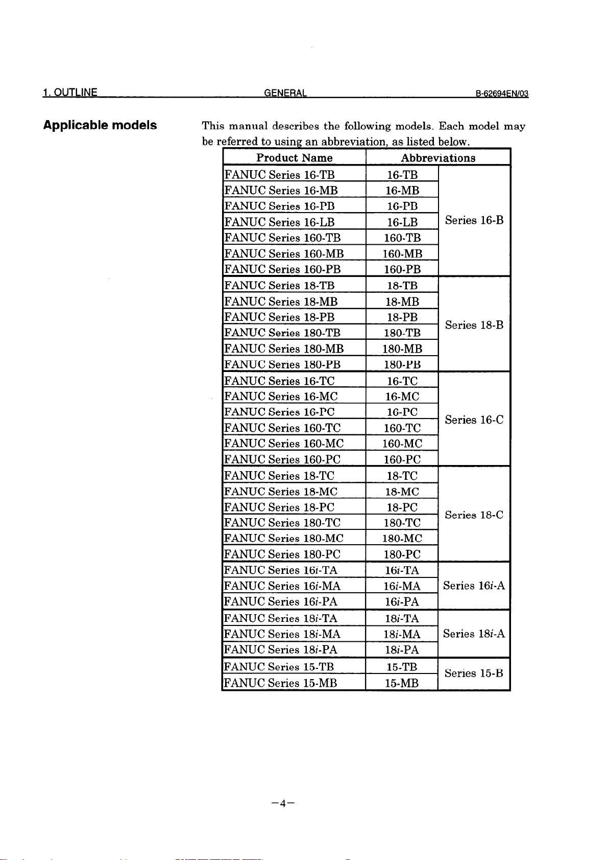
Applicable models
This manual describes the following models. Each model may
be referred to using an abbreviation. as listed below.
I
IFANUC Series 16-TB
FANUC Series 16-MB
FANUC Series 16-PB
FANUC Series 16-LB
IFANUC Series 160-TB 1 160-TB 1
IFANUC Series 160-MB 1 160-MB 1
IFANUC Series 160-PB I 160-PB I
FANUC Series 18TB
FANUC Series l&MB
FANUC Series 18PB
FANUC Series 180-TB
FANUC Series 16-PC
FANUC Series 160-TC
Product Name
!
Abbreviations
16-TB
16-MB
16-PB
16-LB
18-TB
H-MB
18-PB
180-TB
16-PC
160-TC
Series 16-B
I
Series 18-B
Series 16-C
FANUC Series 18-PC
FANUC Series 180-TC
FANUC Series 180-MC
FANUC Series 180-PC
FANUC Series 16i-TA
FANUC Series 16i-MA
FANUC Series 16i-PA
IFANUC Series 18i-TA
IFANUC Series 18i-MA
IFANUC Series 18i-PA
FANUC Series 15TB
FANUC Series l&MB
-4-
18-PC
180-TC
180-MC
180-PC
16i-TA
1 Gi-MA
16i-PA
I 18i-TA I
Series 18-C
Series 16i-A
I 18i-MA I Series 18i-A
I 18i-PA I
15-TB
l&MB
Series 15-B
Page 16
Page 17
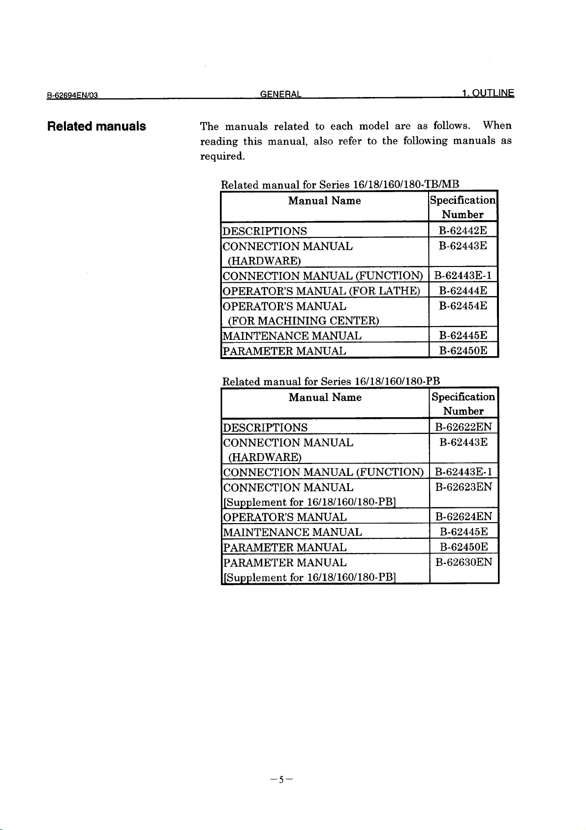
1. OUTLINE GENERAL
Related manual for Series 16-LB
Manual Name Specification
IDESCRIPTIONS
CONNECTION MANUAL
(HARDWARE)
ICONNECTION MANUAL (FUNCTION) 1 B-62443c i 1
CONNECTION MANUAL
JSupplement for 16-LB]
OPERATOR’S MANUAL
MAINTENANCE MANUAL
PARAMETER MANUAL
PARAMETER MANUAL
JSupplement for 16-LB]
Related manual for Series 16/18/160/180-TCYMC
Manual Name
DESCRIPTIONS
CONNECTION MANUAL
(HARDWARE)
CONNECTION MANUAL (FUNCTION) B-62753EN-1
OPERATOR’S MANUAL (FOR LATHE) B-62754EN
OPERATOR’S MANUAL
(FOR MACHINING CENTER)
MAINTENANCE MANUAL B-62755EN
IPARAMETER wu~L 1 B-62760EN 1
B-62694ENIOQ
Number
1 B-62442E 1
B-62443E
-.
B-62593EN
B-62594EN
B62595EN
B-62450E
B-62600EN
Specification
Number
B-62752EN
B-62753EN
B-62764EN
Related manual for Series 16/18/160/180-PC
Manual Name Specification
Number
DESCRIPTIONS B-62772EN
CONNECTION MANUAL B-62753EN
(HARDWARE)
CONNECTION MANUAL (FUNCTION) B-62753EN-1
CONNECTION MANUAL
B-62773EN
JSupplement for 16/18/160/180-PC]
OPERATOR’S MANUAL
B-62774EN
MAINTENANCE MANUAL B-62755EN
PARAMETER MANUAL
B-62760EN
PARAMETER MANUAL B-62780EN
[Supplement for 16/18/160/180-PC]
-6-
Page 18
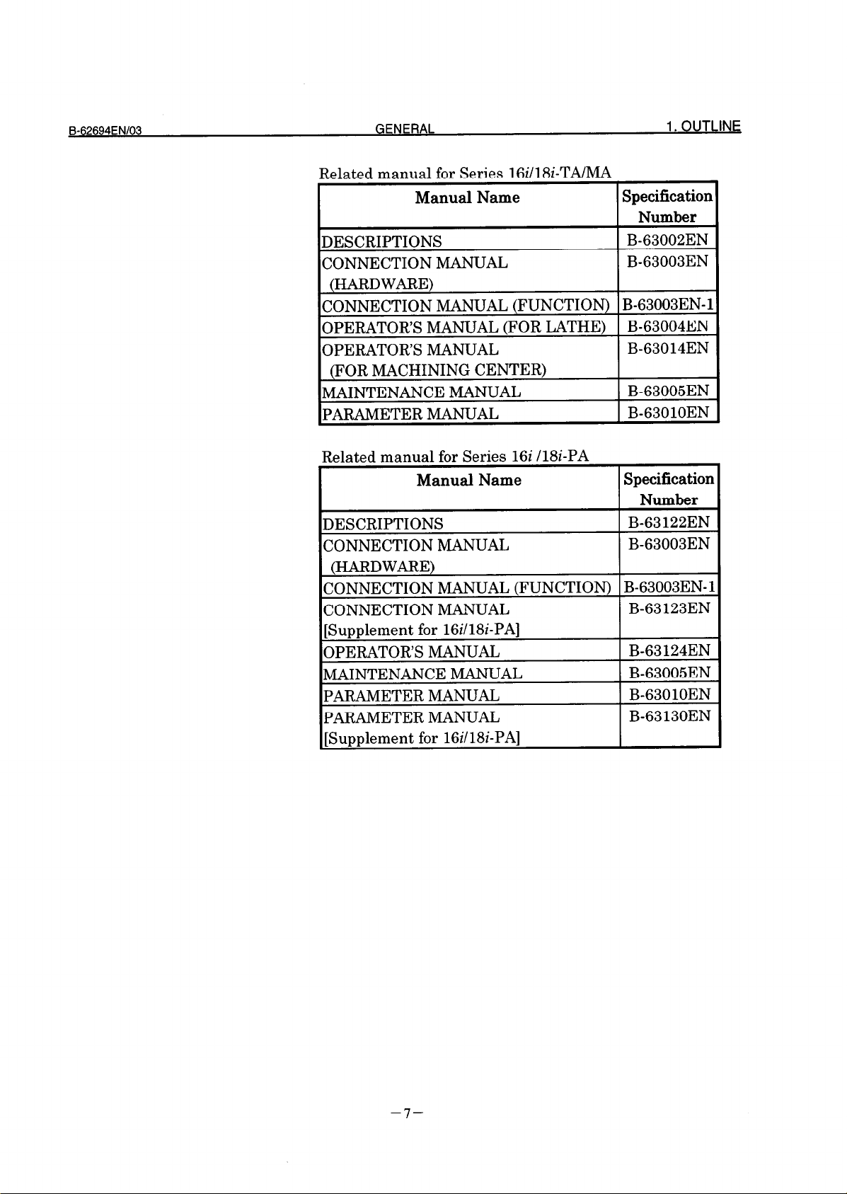
Related manual for Series 16iIl8i-TAIMA
Manual Name
Specification
Number
DESCRIPTIONS
CONNECTION MANUAL
B-63002EN
B-63003EN
(HARDWARE)
CONNECTION MANUAL (FUNCTION) B-63003EN-1
OPERATOR’S MANUAL (FOR LATHE)
OPERATOR’S MANUAL
B-63004EN
B-63014EN
(FOR MACHINING CENTER)
MAINTENANCE MANUAL
~PARAMETER h4mum
B-63005EN
B-63010EN
Related manual for Series 16i /l&-PA
Manual Name
Specification
Number
DESCRIPTIONS
CONNECTION MANUAL
B-63 122EN
B-63003EN
(HARDWARE)
CONNECTION MANUAL (FUNCTION) B-63003EN-1
CONNECTION MANUAL
B-63 123EN
[Supplement for 16i/lSi-PA]
OPERATOR’S MANUAL
MAINTENANCE MANUAL
PARAMETER MANUAL
PARAMETER MANUAL
B-63 124EN
B-63005EN
B-63010EN
B-63 130EN
[Supplement for 16i/18i-PA]
-7-
Page 19
1. OUTLINE
GENERAL
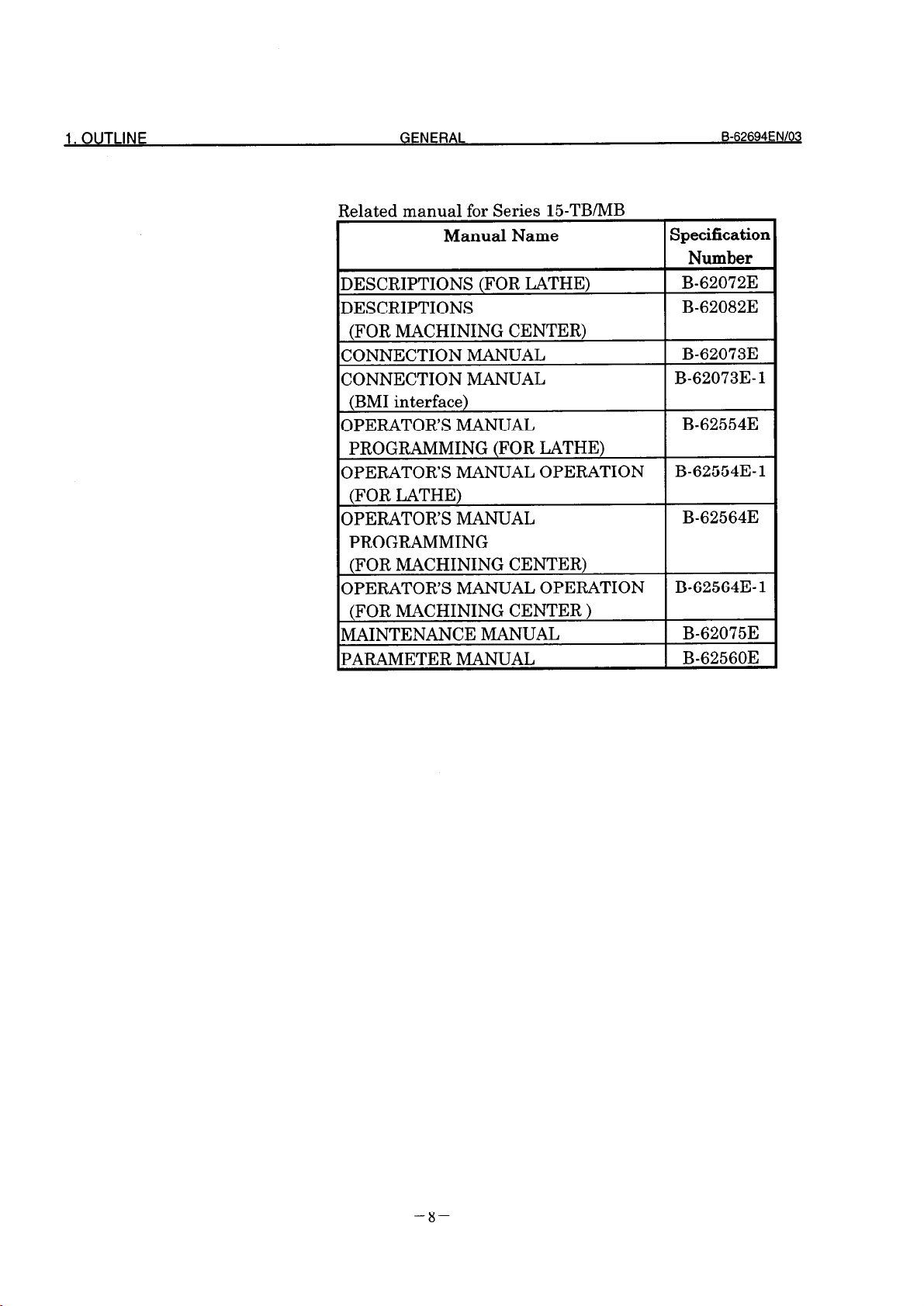
Related manual for Series l&TB/MB
Manual Name
DESCRIPTIONS (FOR LATHE)
DESCRIPTIONS
(FOR MACHINING CENTER)
CONNECTION MANUAL
CONNECTION MANUAL
(BMI interface)
OPERATOR’S MANUAL
PROGRAMMING (FOR LATHE)
OPERATOR’S MANUAL OPERATION
(FOR LATHE)
OPERATOR’S MANUAL
PROGRAMMING
(FOR MACHINING CENTER)
OPERATOR’S MANUAL OPERATION
(FOR MACHINING CENTER )
MAINTENANCE MANUAL
PARAMETER MANUAL
B-62694ENlOQ
Specification
Number
B-62072E
B-62082E
B-62073E
B-62073E- 1
B-62554E
B-62554E-1
B-62564E
B-62564E- 1
B-62075E
B-62560E
-8-
Page 20

Page 21
1 FOR Series 16/18-B/C, Series 15-B
The information for connection of the Data Server interface
for Series 16/18-B/C and Series 15-B is described in this
chapter.
-ll-
Page 22
1. FOR Series 16/l 8-B/C.Series 15-B
CONNECTION
B-62694ENIO;i
II .
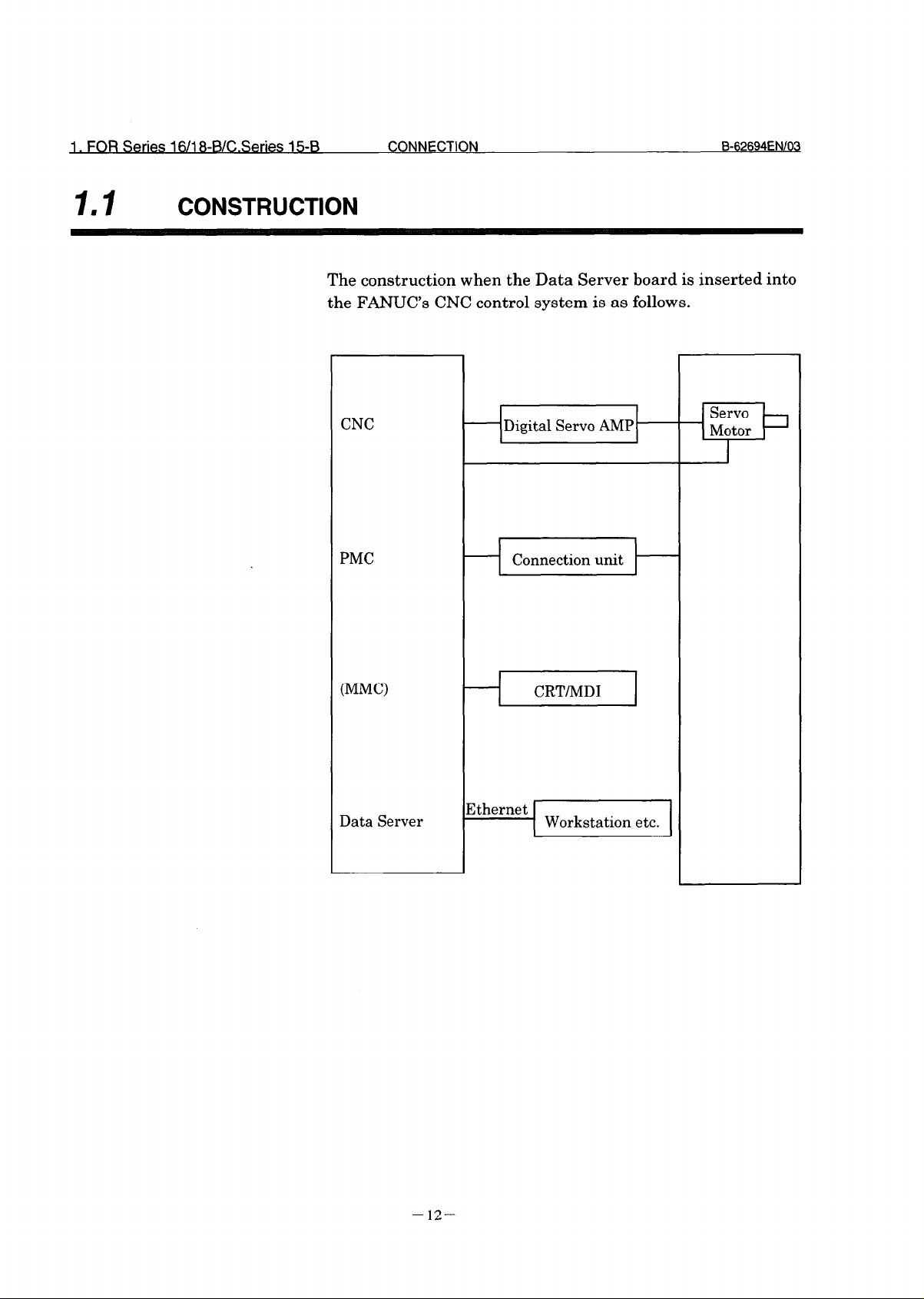
CONSTRUCTION
The construction when the Data Server board is inserted into
the FANUC’s CNC control system is as follows.
CNC
PMC
ADigital Servo AMP)
Connection unit
-I
I-
(MM0
Data Server
+ CRT/MD1 1
Xhernet
Workstation etc.
- 12-
Page 23
B-62694EN/03
CONNECTION
INSTALLATION
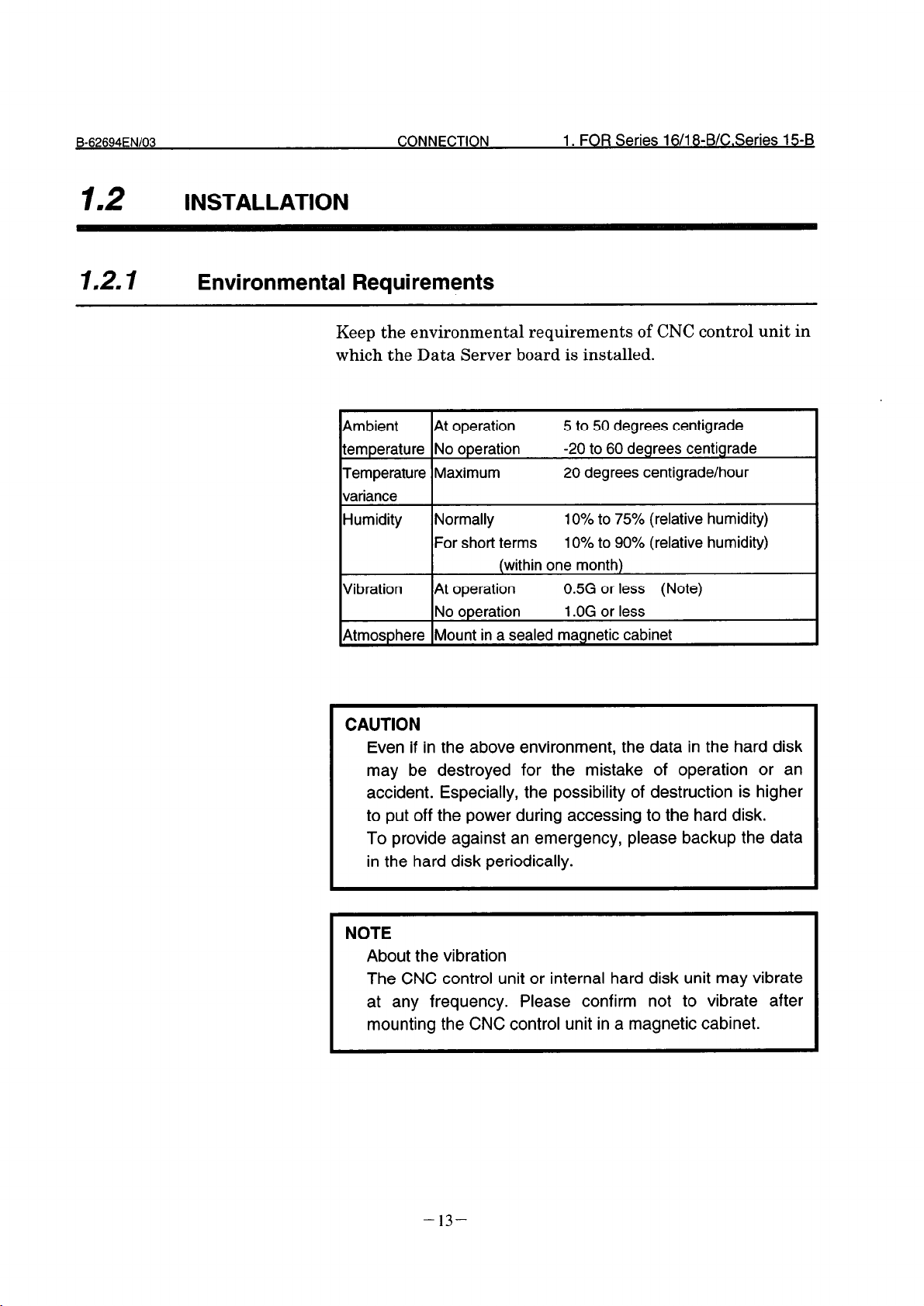
1.2. I Environmental Requirements
Keep the environmental requirements of CNC control unit in
which the Data Server board is installed.
1. FOR Series 16/l 8-B/C.Series 15-B
Ambient
temperature No operation
Temperature Maximum
variance
Humidity Normally
Vibration At operation
Atmosphere Mount in a sealed magnetic cabinet
At operation
For short terms
(within one month)
No operation 1 .OG or less
5 to 50 degrees centigrade
-20 to 60 degrees centigrade
20 degrees centigrade/hour
10% to 75% (relative humidity)
10% to 90% (relative humidity)
0.5G or less (Note)
CAUTION
Even if in the above environment, the data in the hard disk
may be destroyed for the mistake of operation or an
accident. Especially, the possibility of destruction is higher
to put off the power during accessing to the hard disk.
To provide against an emergency, please backup the data
in the hard disk periodically.
NOTE
About the vibration
The CNC control unit or internal hard disk unit may vibrate
at any frequency. Please confirm not to vibrate after
mounting the CNC control unit in a magnetic cabinet.
- 13-
Page 24
1. FOR Series 16/l 8-B/C.Series 15-B
CONNECTION B62694ENlOCj
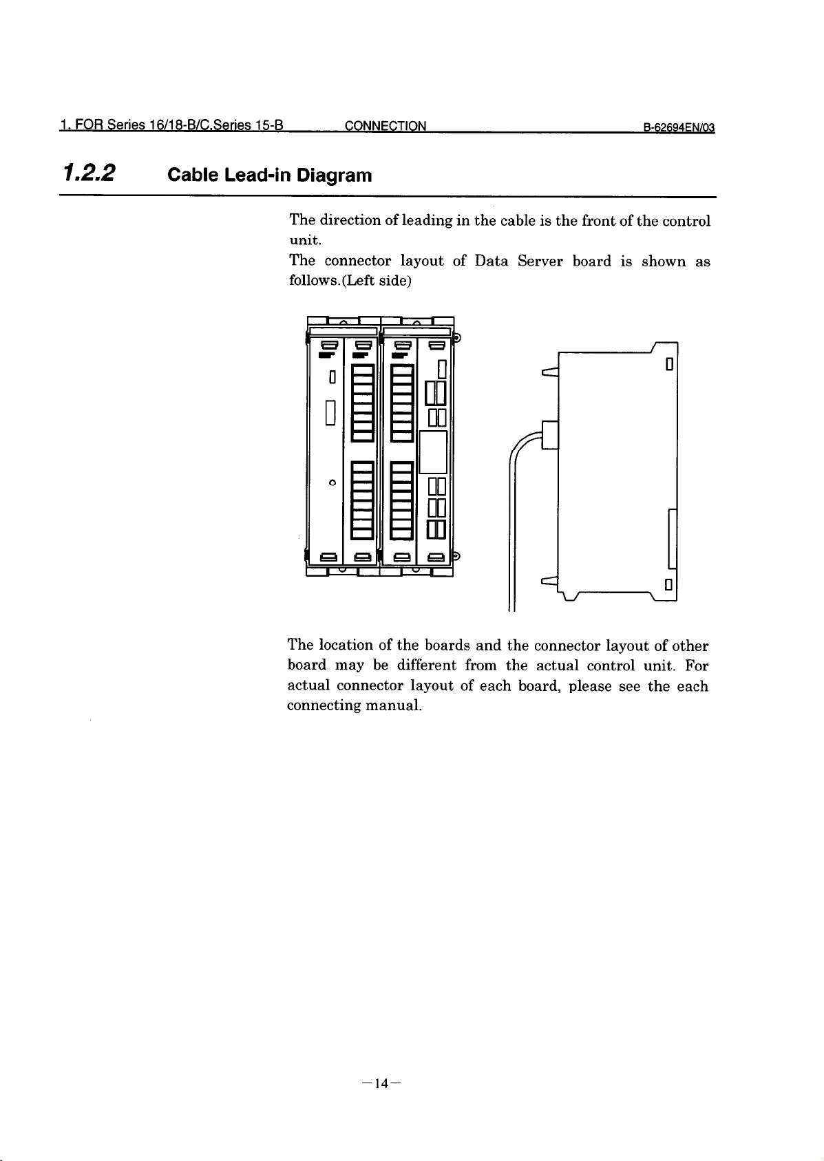
1.2.2 Cable Lead-in Diagram
The direction of leading in the cable is the front of the control
unit.
The connector layout of Data Server board is shown as
follows. (Left side)
The location of the boards and the connector layout of other
board may be different from the actual control unit. For
actual connector layout of each board, please see the each
connecting manual.
- 14-
Page 25
_&62694ENl
CONNECTION 1. FOR Series 8 Se 03 16/l -B/C
ries 15-B
1.2.3
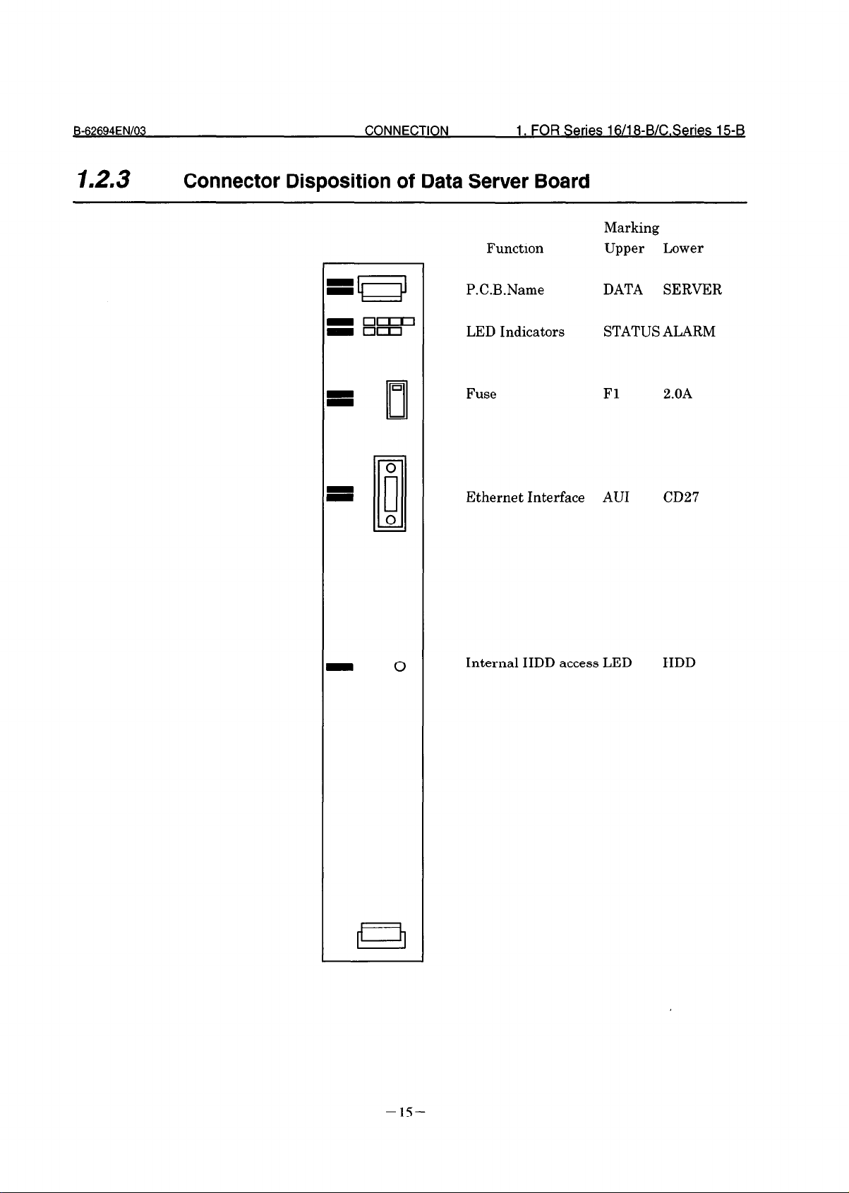
Connector Disposition of Data Server Board
Function
P.C.B.Name
LED Indicators
Fuse Fl 2.OA
Ethernet Interface AU1
Marking
Upper Lower
DATA SERVER
STATUS ALARM
CD27
Internal HDD access LED HDD
- 15-
Page 26
1. FOR Series 16/l 8-B/C.Series 15-B
CONNECTION
13 .
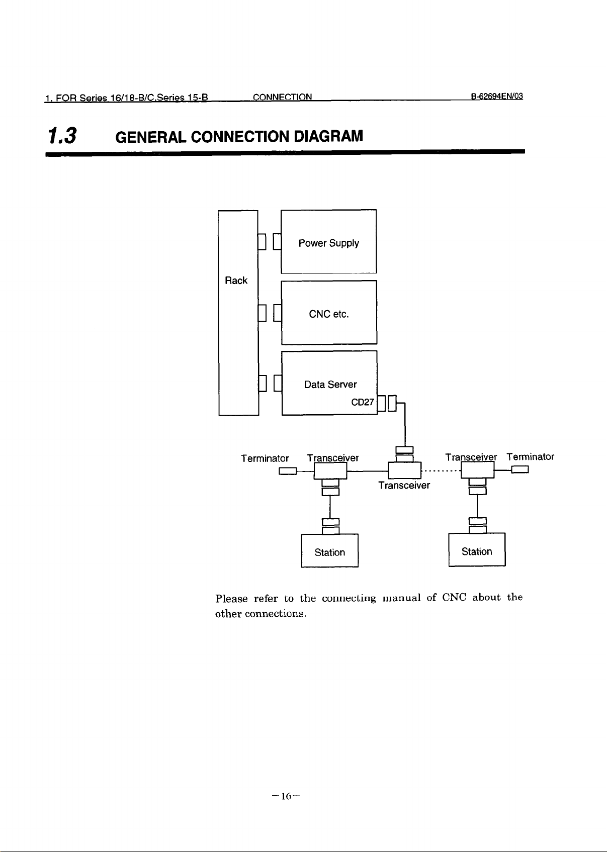
GENERAL CONNECTION DIAGRAM
Power Supply
1
Rack
CNC etc.
li
Terminator
Please refer to the connecting manual of CNC about the
other connections.
Transceiver
- 16-
Page 27
Eb62694ENl03 CONNECTION
2. FOR Series 16i/l8i-A
2
FOR Series 16dl8i-A
The information for connection of the Data Server Interface
board for Series 16i/18i-A is described in this chapter.
- 17-
Page 28
2. FOR Series 16i/l8i-A CONNECTION B-62694ENl03
.
21
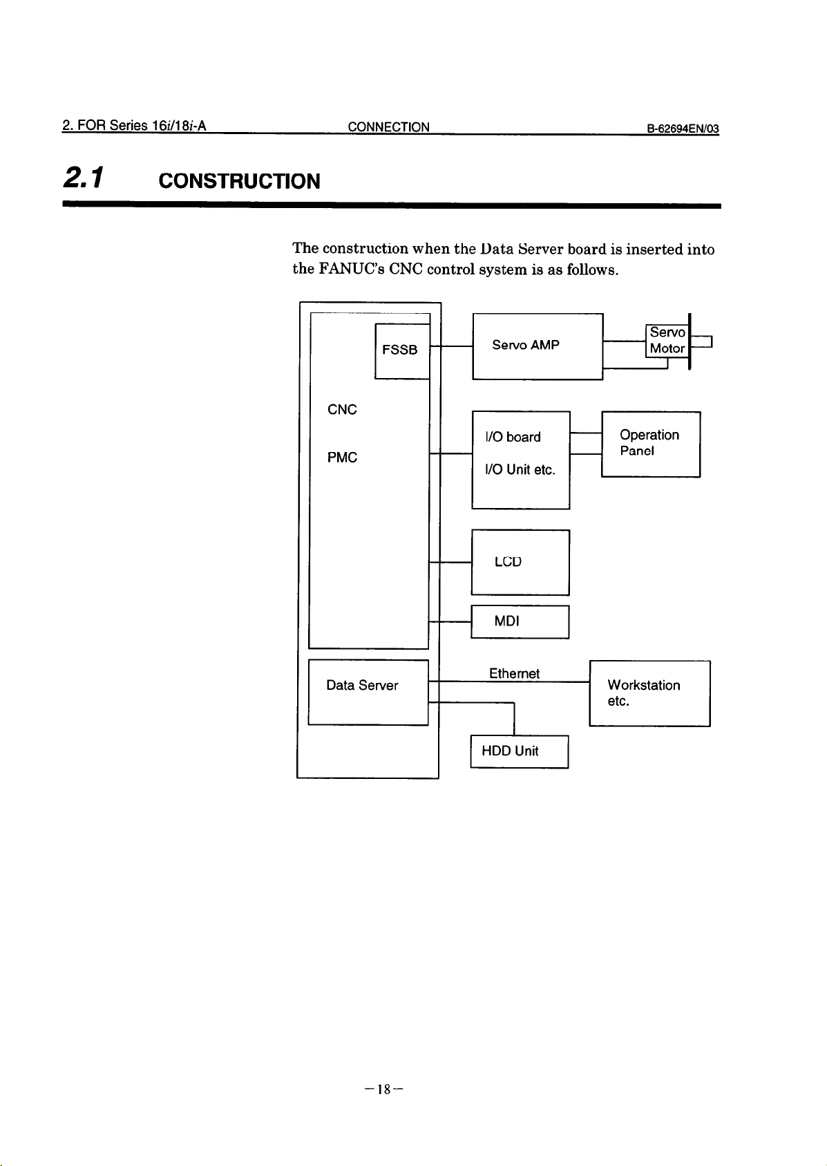
CONSTRUCTION
The construction when the Data Server board is inserted into
the FANUC’s CNC control system is as follows.
FSSB
r
CNC
PMC
Data Server
- Servo AMP
LCD
--I
-1 Workstation
MDI
I
Servo
Allotor 1
-18-
HDD Unit
I
I
Page 29
B-62694ENl03 CONNECTION
22 . INSTALLATION
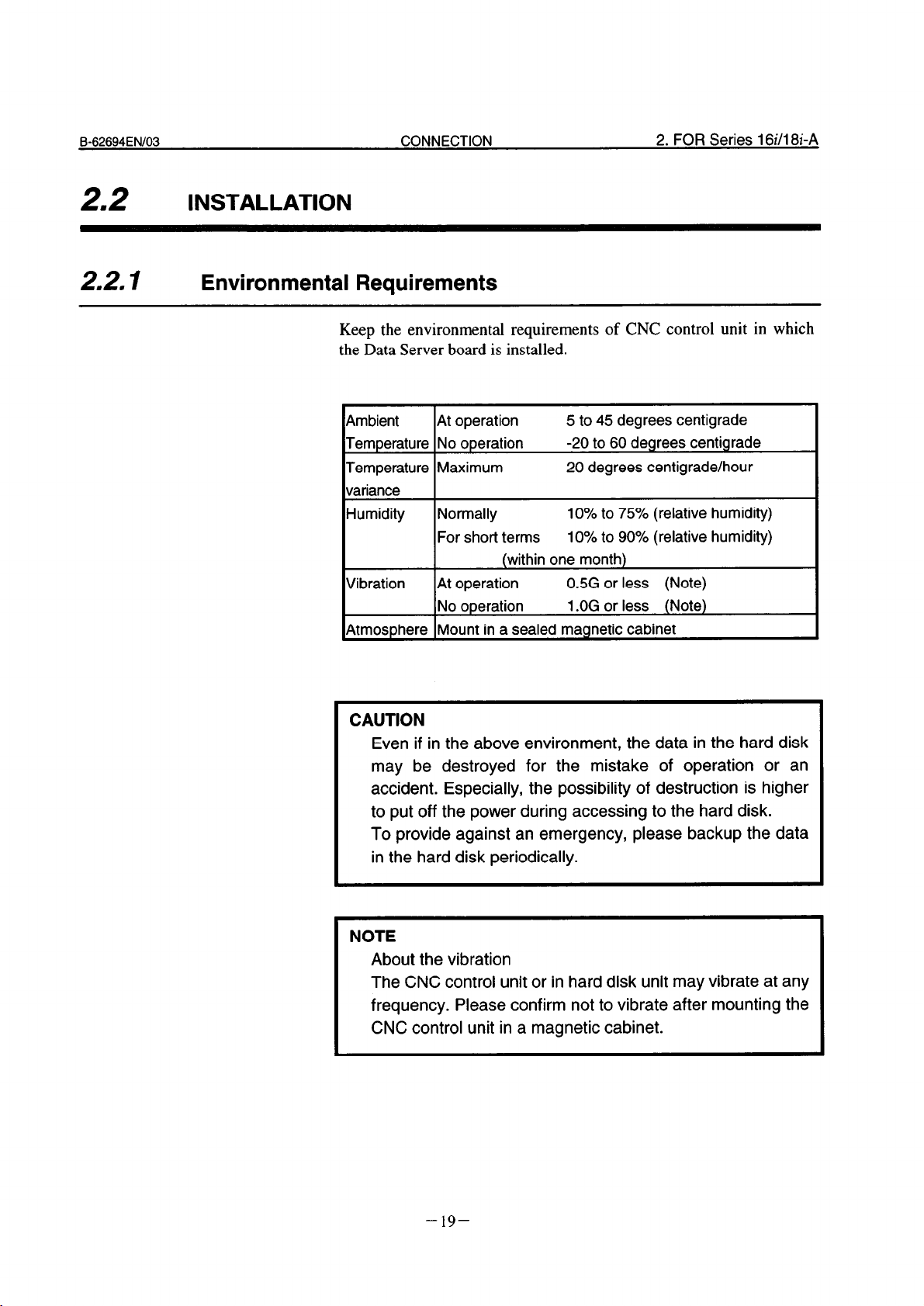
2.2. I Environmental Requirements
Keep the environmental requirements of CNC control unit in which
the Data Server board is installed.
2. FOR Series 16i/18i-A
Ambient At operation
Temperature No operation
Temperature Maximum
variance
Humidity Normally
For short terms
(within one month)
Vibration
Atmosphere Mount in a sealed magnetic cabinet
At operation
No operation
5 to 45 degrees centigrade
-20 to 60 degrees centigrade
20 degrees centigrade/hour
10% to 75% (relative humidity)
10% to 90% (relative humidity)
0.5G or less (Note)
1 .OG or less (Note)
CAUTION
Even if in the above environment, the data in the hard disk
may be destroyed for the mistake of operation or an
accident. Especially, the possibility of destruction is higher
to put off the power during accessing to the hard disk.
To provide against an emergency, please backup the data
in the hard disk periodically.
NOTE
About the vibration
The CNC control unit or in hard disk unit may vibrate at any
frequency. Please confirm not to vibrate after mounting the
CNC control unit in a magnetic cabinet.
-19-
Page 30
2. FOR Series 16i/18i-A
CONNECTION
B-62694EN103
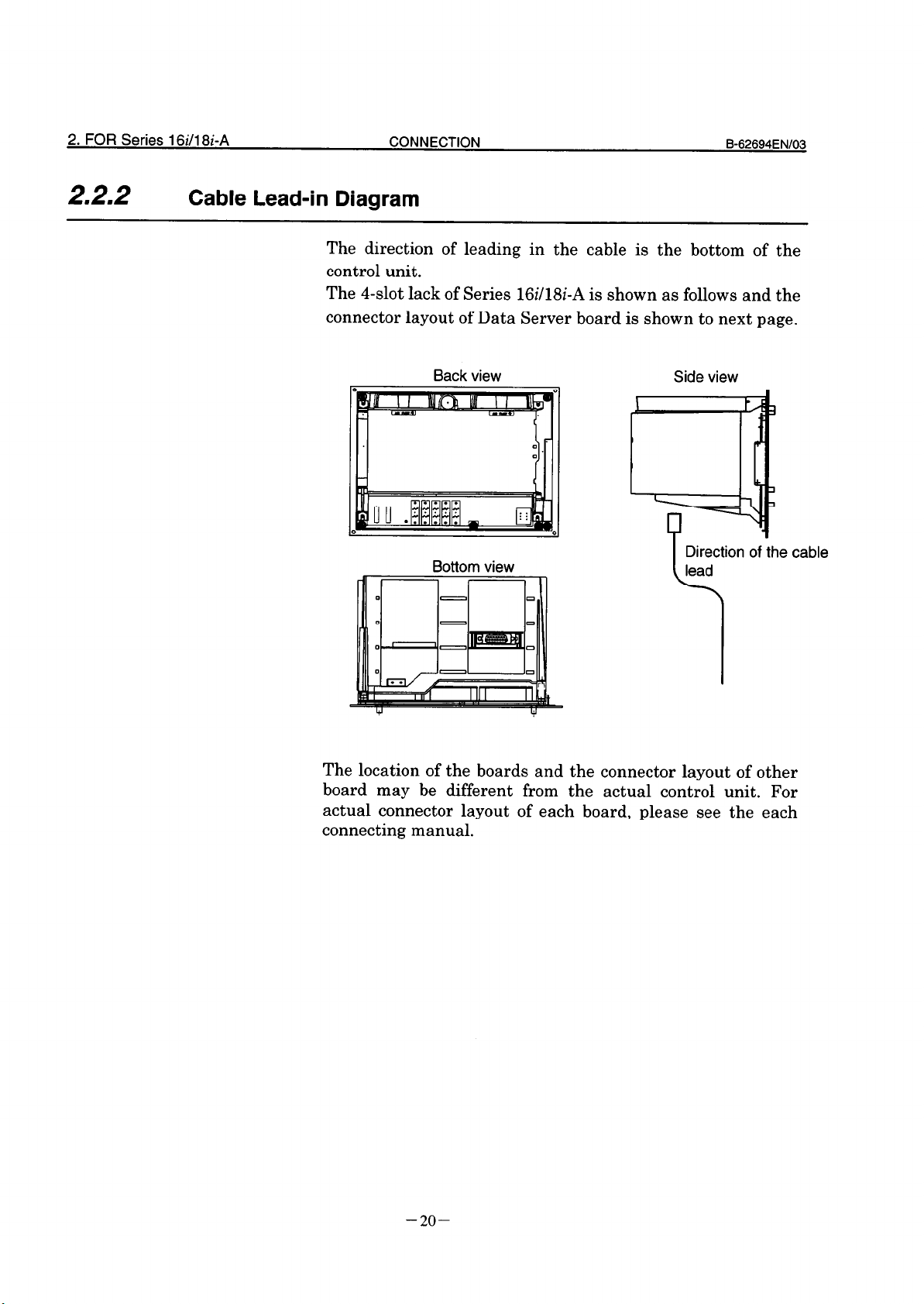
2.2.2
Cable Lead-in Diagram
The direction of leading in the cable is the bottom of the
control unit.
The 4-slot lack of Series 16i/lSi-A is shown as follows and the
connector layout of Data Server board is shown to next page.
Bottom view
Direction of the cable
lead
c
The location of the boards and the connector layout of other
board may be different from the actual control unit. For
actual connector layout of each board, please see the each
connecting manual.
-2o-
Page 31

B-62694ENl03
CONNECTION
2. FOR Series 16i/l8i-A
2.2.3
Connector Disposition of Data Server Board
Total edition OlA only
0 0
0
-
0
Communication LSI
0
-
0
Oil
osc
c
CPU
7
-
CUSTOM
LSI
AU1
CD27
STATUS 1
STATUS 2
STATUS 3
STATUS 4
Parity Alarm
CPU HALT
HDD Access
CUSTOM
LSI
IDD Interface
:NHl
JNA
-21-
Page 32

2. FOR Series 16i/l8i-A
CONNECTION
Total Edition 02B or newer
. I
, , ;__________.:
. I .
I
. 4
* *
. .
. .
I .
. *
. * .
. * .
* * .
. I 8
, , . . . .._.______ *
1
-.___-
p
i Communi- i
i cation LSI i
---.-_.__._
: osc i - 1
’ . _ . . _ . _ . _ _ ,
(....._.___.__..._
I
B-62694EN103
AU1
CD27
CPU HALT
STATUS 4
STATUS 3
STATUS 2
STATUS 1
Parity Alarm
, @l-r
CPU
CUSTOM
LSI
n
I
I
/
CUSTOM
LSI
-
01
HDD Access
HDD Interface
CNHl
Terminal
TM1
-22-
Page 33

Page 34

2. FOR Series 16i/18i-A
CONNECTION
B-62694ENl03
2.3.2
Connection of HDD Unit
The board of total edition 02B or newer must be assemble the
plate which is to prevent slipping out of the hard disk
connector.
To connect or disconnect the hard disk cable, this plate also
need to be connected or disconnected.
(The board of total edition OlA has no terminal to assemble
the plate.)
1) Connection of the cable
2) Assemble of the plate
-
Plat
Terminal
I
LoJ
3) Fix the plate using the screw
To disconnect the hard disk cable, do the reveres way of the
above order.
CAUTION
Before connect or disconnect the cable to Data Server
board, cut the power supply of CNC unit and confirm that
the power is off.
-24-
Page 35

B-62694ENl03
CONNECTION
2. FOR Series 16i/l8i-A
HDD Unit is mounted on the back side of MD1 unit.
The
length of the HDD flat cable is 370mm.
In the case of mounting the MD1 unit apart from control unit,
the hard disk unit is not be able to be connected. So,
considering the cable length of hard disk unit, mount the
MD1 unit as follows.
1 MD1 Unit (Horizontal) 1
Mounting example of MD1 Unit
0
MD1 Unit (Vertical)
-25-
Page 36

3. CONNRXION WI-W NFTWORK
CONNFCTION
B-6%94FNIQ
3
CONNECTION WITH NETWORK
In this chapter, we describe the information about the
connection to the Ethernet.
CAUTION
Before connect or disconnect the cable to Data Server
board, cut the power supply of CNC unit and confirm that
the power is off.
NOTE
Please inquire of each maker about the construction of
network or the condition of using the equipment except the
Data Server (transceiver and cable etc.) . To construct the
network, it is necessary not to be influenced by the noise.
Separate the network line electrically from the noise source
as power line and motor etc..
of each equipment must be done. And the high impedance
to the ground makes the obstacle of communication.
Please test and confirm the communication before working
the machine in earnest.
The network trouble which is case of the equipment except
the Data Server is not guaranteed by FANUC.
And the ground treatment
-26-
Page 37

. CONNECTION WITH THE ETHERNET
31
MAU (Media Attachment Unit : Transceiver)
Coaxial cable
\
Transceiver cable
Te<minator
I I
AL
C
I
I
MAU
StaGn
Items Marks
Maximum segment length a 500m
Length
transceiver
Length of transceiver cable C Maximum 50m
Node number per segment n Maximum 100
MAU : TDK : CIU-1000 Ethernet Transceiver or equivalent
Set for IEEE802.3 standard. (Include the hart-beat function)
NOTE
1. The transceiver must be connected to
Server using the transceiver cable. The
should be shielded. (Refer 3.4 )
2. The SQE TEST function (Hart-beat
transceiver must be set. There are some transceivers that
the setting switch or jumper are inside the transceiver.
I
between the b On the marking at intervals of
(Transceiver)
Conditions
2.5m
the AUI of Data
transceiver cable
function) of the
-27-
Page 38

3. CONNFCTION WITH NFTWORK
.
32
AUI (Attachment Unit Interface) PIN CONFIGURATION
CONNFCTION
CD27 D-sub 15pin
Fb67694FNlCQ
-28-
Page 39

Page 40

3. CONNFCTI~N W-W bE!-WOW
. SHIELDING EARTH OF THE TRANSCEIVER CABLE
34
The transceiver cable should be clamped by the method as
shown below. This cable clamp treatment is not only for cable
support but also for shield-treatment. As it is very important
for stable operation of the system, perform this treatment.
Peel out the sheath partially as shown in the following figure
and expose the shield. Push and clamp by the plate metal
fittings for clamp at the part.
CONNWTION B-67694FNlOa
Ground plate
Cable
Metal fittings for clamp
Peel of cable ’
Transceiver cable
Hitachi-densen LTD Transceiver cable or equivalent
-3o-
Page 41

8-@‘694FN/O3
CONNFCTION
3. CONNECTION WITH NFTWORY
, Ground plate
Example for shield treatment of transceiver cable
Prepare ground plate like the following figure.
Mount screw hole
Ground terminal
Clamp metal hole
(grounded)
Ground plate
For the ground plate, use a metal plate of 2mm or thicker,
which surface is plated with nickel.
-31-
Page 42

3. CONNFCTlON WITH NETWORK
hGroun;_
CONNFCTION
t-t,
Fi m
I
1 20mm 4 i /
Ground plate holes
Max 55mm
B-67Fi94FNIOC$
Cable clump outer diagram
Order specification for cable clump
AOZB-0083-K301 ( 5 pieces )
-32-
17mm
Page 43

Page 44

EO/N36929-9
33NVN31NIVW
g-9 1 =!-JaS 38-8 l/9 1 =!JaS tlOJ- 1
9-a =!a ‘3/a=8c/9c sa!Js kiOA
-SE-
Page 45

11 .
SYSTEM BLOCK DIAGRAM
A
Power Supply Unit
CNC Main CPU Board
Other Option Board
I I I I I
1 ROM 1-w-j HDD 1
I ,
CPU
IH
-
-
-
Name
Data Server Board
Custom
LSI
LAN
Controller
I -
DRAM
Ko
SRAM
Data Server P.C.B.
Specification
A16B-2202-0630
DViRV
Note
lOBASE
1
CNl
HDD Unit
Fuse
-36-
A02B-0207-CO50
A02B-0207-CO5 1
A02B-0207-CO53
AO8R-0048-K 10 1
85MB
256MB
810MB
2.OA
Page 46

B-62694EN/03
MAINTENANCE
1 .FOR Series 16/l 8-B/C. Series 15-B
12 .
PARTS LAYOUT
Specification : A02B-02 13- JO0 1
Printed
letters
DATA
SERVER
0
0
0
0
STATUS
ALARM
Fl
2.OA
AUI
CD27
LED c
0
0
+12vo
[
=
=
0
II
Back Plane Connector HDD
c
HDD
0
-37-
Page 47

1 .FOR Series 16/l 8-B/C. Series 15-B
MAINTENANCE
B-62694ENl03
.
13
LIGHTING OF LEDS AND MEANING
In the Data Server board for Series 16/18-B/C and Series 15
B, there are four green LEDs for “STATUS”, three red LEDs
for “ALARM” and one green LED for “HDD”.
In the following explanation, status of LED is expressed as
follows.
q : Turn off
n : Turn on
IATA
SERVER
El
STATUS &&&A
PILARM 000
The indication of LEDs when turning on the power
‘ower off
nitial state of power injection
5 1 STATUS q ltlHW
0 : Don’t care
State of Data Server Board
Main memory test
Ethernet RAM test
9 1 STATUS q IOCID
I
10 1 STATUS n mWl
Under checking Initialization of s stem area
Hardware
FANUC BUS Interrupt test 1
FANUC BUS Interrupt test 2
FANUC BUS Interrupt test 3
FANUC BUS Interrupt test 4
Initialization of
interrupt
When the Data Server Software runs normally, the status of
LEDs becomes the state of 14.
-38-
Page 48

B-62694ENl03
MAINTENANCE
1 .FOR Series 16/l 8-B/C. Series 15-B
The indication of LEDs(STATUS) when an error occurs
LEDs of “STATUS’ repeat the pattern of “LONG” and
“SHORT”. The pattern of “LONG” is indicated long and the
pattern of “Sl
[ORT” is indicated short.
LEDs (
LONG
No.
1234
q llJcl~
1
x--pi
cnmm
8
I
9 I IJclmm
clclmm
12
(Note) When
STATUS)
SHORT
1234
q ICIKI Defect of main memory
Check the Data Server P.C.B.
Kill Defect of Ethernet RAM
Check the Data Server P.C.B.
lXw0 Defect of Common RAM
ICheck the Data Server P.C.B.
0000 Unexpected interrupt to the CPU
occurred.
0000 Unexpected interrupt to the CPU
occurred.
0000 Unexpected interrupt to the CPU
occurred.
~000 The system error occurred in the Dat
Server software.
¤~~~ Bus error of FANUC BUS occurred.
Check the Data Server P.C.B.
q B00 Parity error of main memory occurred.
n KICI Parity error of Ethernet RAM occurred.
q ICIKI Parity error of Common RAM occurred.
n 0Kl Refresh toward the main memory wa
interrupted beyond the fixed conditio
time.
,hese errors occur, please contact FANUC.
State of Data Server board
(Note)
(Note)
(Note)
(Note)
The indication of LEDs(ALARM) whc
LEDs
ALARM
ALARM
1 ALARM
-39-
47 an error occurs
123 State of Data Server board
HO0 Parity error of main memory, Ethernet
RAM or Common RAM occurred, or refresh
toward the main memory was interrupted
beyond the fixed condition time. Identify
the defect and exchange by referring tc
“STATUS” LED from No.9 to No. 12.
OWO The fuse is broken. Exchange the fuse.
0Om CPU is in HALT state or SHUTDOWN
state. Check the Data Server P.C.B.
Page 49

1 .FOR Series 160 8-B/C. Series 15-B
MAINTENANCE B-62694EN/03
14 .
HOW TO EXCHANGE A FUSE
(1)Check a fuse on the front panel of the Data Server P.C.B.
and confirm whether it is broken.
There is a little window in the fuse and a white marker
appears there at the time of the breakage.
(2)Remove the cause of the fuse cutting.
(3)After the broken fuse is pulled out, insert the new fuse of
the same specification.
- Fuse
Fuse Specification :
A08B-004%KlOl
Capacity : 2.OA
Use : For Ethernet power
-4o-
Page 50

B62694EN/03
MAINTENANCE 2.FOR Series 16i/l8i-A
2
FOR Series 16i/l8i-A
In this section, the maintenance information about Series
16i/18i-A is described.
-4l-
Page 51

2.FOR Series 16dl8i-A MAINTENANCE
SYSTEM BLOCK DIAGRAM
CNC Main CPU Board
B-62694EN/03
4
Other Option Board
Ethernet _
CPU
Custom -
LSI
CJ
Cl
Data Server P.C.B.
AUI
1
CD27
HDD
CNHl
I
Name Specification Note
Data Server Board AZOB-8100-0160
Sub Board A20B-2002-0590 latter edition than 02B
HDD Unit A02B-0236-C252
Note)
In case of latter edition than 02B, the DC/DC
converter is loaded on the sub board.
-42-
810MB
Page 52

B-62694EN/03
MAINTENANCE
2.FOR Series 16i/l8i-A
22 .
PARTS LAYOUT
Parts Layout (Only 0 1A edition)
ommunicati n
Controller
cl
0 0
0
Custom
LSI
c
I
1
c
AUI
CD27
STATUS 1
STATUS 2
STATUS 3
STATUS 4
Parity Alarm
CPU HALT
HDD Access
-43-
u-
HDD Interface
CNHl
JNA
E
Page 53

2.FOR Series 16i/l8i-A
MAINTENANCE
Parts Layout (Latter edition than 02B)
B-62694ENl03
7
J
Interface Board : AZOB-2002-0590
Custom c
LSI
AUI
CD27
CPU HALT
STATUS 4
STATUS 3
STATUS 2
STATUS 1
Parity Alarm
HDD Access
Custom
LSI
0
7
1
HDD Interface
CNHl
Terminal
0
c
TM1
JNA
E
-44-
Page 54

B-62694ENl03
MAINTENANCE
2.FOR Series 16i/l8i-A
.
23
LIGHTING OF LED AND MEANING
In the Data Server Board for Series 16i/18i-A, there are four
green
one green LED for “HDD”. But, LEDs’ position is different by
the edition of the Data Server board.
The LEDs’ position is displayed for each edition.
In the following explanation, status of LED is expressed as
follows.
LEDs for “STATUS”, two red LEDs for “ALARM” and
0 : Turn off
n : Turn on
0 : Don’t care
-45-
Page 55

2.FOR Series 16i/l8i-A
MAINTENANCE
2.3. I In Case of Edition 01 A
B-62694EN103
The indication of LEDs when turning on the power
LEDs
No.
1
STATUS 0000 Power off
2 STATUS WmmH Initial state of power injection
3 1 STATUS n m=Cl
4 1 STATUS WHO1
5 1 STATUS HKl0
6 1 STATUS WClHm Under checking
7 1 STATUS WClmU
8 1 STATUS KlClW
9 1 STATUS HClCllJ
10 1 STATUS q lmmH
11 STATUS IJ~MCI
I
12 STATUS q IKI~ Boot up Initialization of BIOS
13 STATUS q lKl0 Data Server Loading software to
14 STATUS 000~ Boot up completely
When the Data Server Software runs normally, the status of
LEDs becomes the state of 14.
4321
Hardware
software
State of Data Server Board
I
Main memory test
Ethernet RAM test
Common RAM test
Initialization of system area
FANUC BUS Interrupt test 1
FANUC BUS Interrupt test 2
FANUC BUS Interrupt test 3
FANUC BUS Interrupt test 4
Initialization of
controller
memory
interrupt
main
-46-
Page 56

B-62694ENl03
MAINTENANCE
The indication of LEDs(STATUS) when an error occurs
LEDs of “STATUS” repeat the pattern of “LONG” and
“SHORT”. The pattern of “LONG” is indicated long and the
pattern of “SHORT” is indicated short.
LEDs (STATUS)
LONG SHORT
IO.
4321 4321
KICKI q lKI0 Defect of main memory
1
Check the Data Server P.C.B.
WI00 q l~Cl~ Defect of Ethernet RAM
2
Check the Data Server P.C.B.
KICKI q WKl Defect of Common RAM
3
Check the Data Server P.C.B.
KICI~ 0000 Unexpected interrupt to the CPU
4
occurred.
WXCl 0000 Unexpected interrupt to the CPU
5
occurred.
WElam 0000 Unexpected interrupt to the CPU
6
occurred.
WBKI q ICICI~ The system error occurred in the Dat,
7
Server software.
n m00 q 00m BUS error of FANUC BUS occurred.
8
Check the Data Server P.C.B.
n KICI q IOKI Parity error of main memory occurred.
9
mm00 q CImm Parity error of Ethernet RAM occurred.
10
mm00 q I~CICI Parity error of Common RAM occurred.
11
State of Data Server board
2.FOR Series 16i/l8i-A
(Note)
(Note)
(Note)
(Note)
The indication of LEDs(ALARM) when an error occurs
.
Lighting LED
Parity Alarm
State of Data Server board
n Parity error of main memory, Ethernet
RAM or Common RAM occurred. Identify
the defect and exchange it by referring to
“STATUS” LED from No.9 to No.11.
CPU HALT
n CPU is in HALT state or SHUTDOWN
state. Check the Data Server P.C.B.
-47-
Page 57

2.FOR Series 16i/l8i-A
MAINTENANCE
B-62694ENl03
2.3.2’
In Case of Latter Edition than 02B
Note) The Sub Board is displayed by a dotted line.
The indication of LEDs when turning on the power
LEDs 1234
No.
1
STATUS 0000 Power off
2
STATUS WmHm Initial state of power injection
STATUS ElmHW
3
STATUS HnmH
4
STATUS 00~~
5
STATUS HKIH
6
STATUS IJKlH
7
STATUS n 00m
8
STATUS q KIIJ~
9
STATUS n mKl
10
STATUS q lWWl
ii
12
13
14
When the Data Server Software runs normally, the status of
LEDs becomes the state of 14.
Under checking
Hardware
State of Data Server Board
I
Main memory test
Ethernet R4M test
Common BAM test
Initialization of system area
FANUC BUS Interrupt test 1
FANUC BUS Interrupt test 2
FANUC BUS Interrupt test 3
FANUC BUS Interrupt test 4
Initialization of
interru
-48-
Page 58

&62694EN/03
MAINTENANCE
The indication of LEDs(STATUS) when an error occurs
LEDs of “STATUS” repeat the pattern of “LONG” and
“SHORT”. The pattern of “LONG” is indicated long and the
pattern of “SHORT” is indicated short.
2.FOR Series 16i/l8i-A
.-.
1234 1234
q ICIO~ q IIJ~CI Defect of main memory
1
State of Data Server board
e system
error occurre
C BUS occurred.
(Note) When these errors occur, please contact FANUC.
The indication of LEDs(ALARM) when an error occurs
No.
Lighting LED State of Data Server board
1
Parity Alarm
n Parity error of main memory, Ethernet
RAM or Common RAM occurred. Identify
the defect and exchange it by referring to
“STATUS” LED from No.9 to No. 11.
2
CPU HALT
n CPU is in HALT state or SHUTDOWN
state. Check the Data Server P.C.B.
-49-
Page 59

Page 60

1
FOR Series 16/l 8-B/C, Series 16ill8i-A
The operation of Data Server for Series 16/18-B/C and Series
16i/18i-A is described in this chapter.
-53-
Page 61

1 .FOR Series 16/l 8-B/C, Series 16ill8i-A OPERATION
B-62694EN103
11 I
OUTLINE
By using this function, the following items can be achieved.
(l)Drive high-speed machining operation by calling the
subprogram from a built-in hard disk on the Data Server
board (described as “HDD” below).
(2)Input a NC program in the Host Computer into the HDD
by using FTP.
Output a NC program in the HDD into the Host Computer
by using FTP.
(3)Input a NC program in the HDD into the memory of the
CNC.
Output a NC program in the memory of the CNC into the
HDD.
(4)Delete NC programs and display the table of NC programs
in the HDD.
NOTE
There is the software option “PROGRAM NUMBER 08-
DIGIT” in the Series 16/18-C and Series 16i/l8i-A, but the
Data Server function doesn’t support this feature.
So, the Data Server function and the software option
“PROGRAM NUMBER 08-DIGIT” are not used at the
same time.
-54-
Page 62

B62694ENl03
OPERATION
1 .FOR Series 16/l 8-B/C. Series 16i/l8i-A
1.1. I
Notice when You Use for the First Time
WARNING
1 If you use this function for the first time, you must initiate
the HDD according to “1.8.2 Formatting the Built-in Hard
disk” and input the setting data according to “1.2 SETTING
SCREEN”. And turn off and then turn on the power of the
CNC.
If you use this function before you operate these, we don’t
guarantee that this function operates normally.
2 About FTP on the Ethernet, when you use this function for
the first time, please set Ethernet addresses carefully and
check this function on your environment according to your
network administrator’s advice.
If you set wrong Ethernet addresses, it may make a heavy
effect on your network.
CAUTION
1 If you turn off the power during reading the data from the
HDD or writing to the HDD, it may make the registered file
in the HDD broken.
So, you must not turn off the power during executing the
Data Server functions.
2 Be sure to take the backup of the data in the HDD against
an emergency.
-55-
Page 63

1 .FOR Series 16/l 8-B/C, Series 16i/l8i-A OPERATION
I SETTING SCREEN
12
By using this screen, you can set the data to transfer a NC program
between the HDD and the Host Computer with FTP.
You must set the data shown as the section “1.2.1 Description of Each
Data” before you use the Data Server functions.
Procedure
(l)Press SySTm the function key.
(1
(2)When the softkey [DS-SET] isn’t displayed, press the continuous
menu key several times.
@Press the softkey [DS-SET]. The following screen is displayed.
When the data are already registered, their contents are displayed.
(4)Input the data by using the MD1 keys and the softkeys.
DATA SERVER SETTING-l 00001 NO0010
(HOST-COMPUTER)
IP ADDRESS
I I
USER NAME
I
I
I
I
+
1
l I
----_--------------------------
PASSWORD
-------------------------------
HOST DIRECTORY
________---_--------------------
--------------------------------
--------------------------------
B-62694ENl03
Change two screens
by using the page
1 &I *** STOP *** Lo;-::5
[STRING][ LOCK ][ INPUT ] [ CHECK I[ SET ]
IP ADDRESS
b
MASK ADDRESS
---------------
---------------
1 ;DI *** STOP *** “z:;,;;;G
[STRING][ LOCK I[ INPUT 1 [ CHECK ][ SET 1
-56-
Page 64

Page 65

1 .FOR Series 16/l 8-B/C, Series 16i/l8i-A
OPERATION
B-62694EN103
1.2. I
Description of Each Data
.) Setting data of the Host Computer
(a
(DATA SERVER SETTING- 1)
IPADDRESS IP address of the Host Computer’s Ethernel
USER NAME User name of the Host Computer
PASSWORD Password for the above “USER NAME”
HOST
DIRECTORY to communicate with the Data Server
You can input small letters in these items.
Please see the section “1.2.3 How to Input Small Letters”.
(b) Setting data of the Data Server
(DATA SERVER SETTING-2)
board
( Ex. : “192.168.0.1” )
( Max. 31 letters )
This password must be set.
( Max. 31 letters )
Working directory of the Host Computer in order
( Max. 127 letters )
MAC MAC address of the Data Server board
ADDRESS You must input the 12 alphanumerical let1
printed as the “ADR” at the seal on the D
Server board.
( Ex. : “080019ABCDEF”’ )
IP ADDRESS IP address of the Data Server board
( Ex. : “192.168.0.2” )
MASK Netmask for the network
ADDRESS ( Ex. : “255.255.255.0” )
CAUTION
1 If you change the above “(b) Setting data of the Data
Server” data, you must turn off the power of the CNC once.
2 You must input the 12 alphanumerical letters printed as the
“ADR” at the seal on the Data Server board into the MAC
address.
If you set the wrong address into the MAC address, it may
make a heavy obstacle on your network.
-58-
Page 66

B-62694EN103
OPERATION
1 .FOR Series 16/l 8-B/C, Series 16i/l8i-A
The meanings of each address are as follows:
MAC ADDRESS
: It means the address that identifies
each machine connected by Ethernet in
the MAC layer.
It must be unique in the network.
IP ADDRESS
: It means the address that identifies
each machine connected by Ethernet in
the Network layer.
It must be unique in the network.
MASK ADDRESS : It means a bit typed value which takes
out the part of the network address
from the IP address.
Refer to “APPENDIX C. ETHERNET TECHNICAL
TERMS” in detail.
-59-
Page 67

1 .FOR Series 16/l 8-B/C, Series 16i/l8i-A
OPERATION
B-62694ENl03
1.2.2
Procedure
How to Input Data
In this section, how to input data is explained.
(1)Move the cursor to an item that you wiII input.
(2)Input the data by using the MD1 keys.
(s)Press the softkey [INPUT].
In this screen, the MD1 key
Ex.) In case of setting “192.168.0.1” into the IP ADDRESS
item
(1) Move the cursor and put the cursor on the IP
INWT can’t be used.
I:
ADDRESS item.
DATA SERVER SETTING-l
(HOST-COMPUTER)
IP ADDRESS
USER NAME
>
MD1
1 [STRING] [ LOCK I [ INPUT I[ CHECK I [ SET 11
*** STOP
00001 NO0010
***
12:34:56
I
(2) Input the data “192.168.0.1” by using the MD1 keys.
DATA SERVER SETTING-l
(HOST-COMPUTER)
IP ADDRESS
USER NAME
> 192.168.0.1
MD1
[STRING] [ LOCK ][ INPUT I[ CHECK ][ SET ]
*** STOP **k
00001 NO0010
12:34:56
(3)Press the softkey [INPUT].
DATA SERVER SETTING-l
(HOST-COMPUTER)
IP ADDRESS
USER NAME
MD1
[STRING][ LOCK I[ INPUT ][ CHECK ][ SET ]
I
*** STOP *k*
00001 NO0010
12:34:56
-6O-
Page 68

B-62694ENl03
OPERATION
1 .FOR Series 16/l &B/C, Series 16i/l8i-A
NOTE
The above setting data of Data Server are different from
other NC parameters. They are saved in the HDD.
Therefore you must save the setting data after inputting or
changing these data.
Please refer to the section “1.2.5 How to Save Modified
Data”.
-61-
Page 69

1 .FOR Series 16/l 8-B/C, Series 16Ul8i-A OPERATION
B-62694EN103
1.2.3
Procedure
How to Input Small Letters
When you input the setting data for the Host Computer, you
can input small letters.
How to input small letters is described as follows.
(1)Press the softkey [ LOCK ] before inputting small letters.
Confirm the “LOCK : ON” on the right and low of the
screen.
(z)Then the inputted letter from the MD1 keys is changed to a
small letter.
(3)To cancel this mode, press the softkey [ LOCK ] again or
set the data by using the softkey [INPUT].
Confirm the “LOCK : OFF” on the right and low of the
screen.
-62-
Page 70

B-62694ENi03 OPERATION
1 .FOR Series 16/l 8-B/C, Series 16i/l8i-A
1.2.4
Procedure
How to Set a Host Directory
The data in the HOST DIRECTORY can be specified with
maximum 127 letters. But the data can be inputted with
maximum 32 letters once, so that you can’t specify the data
completely once, In this case, refer to the following.
Ex.) In case that you specify “/DATASERVER/NCPROGRAM
/LINEOO1/GROUP0002”
(1)Move the cursor and put it on the “HOST DIRECTORY”.
HOST DIRECTORY
-8
>
MD1
[STRING] [ LOCK I [ INPUT I [ CHECK I [ SET I
--------------------------------
--------------------------------
--------_--____-____------------
*k* STOP k**
LOCK : OFF
12:34:56
(z)Press the softkey [STRING], so that the cursor
and the
softkeys are changed as follows.
HOST DIRECTORY
~-------------------------------
--------------------------------
-------------------------------LOCK : OFF
>
MD1
[ EXIT I[ LOCK ][INSERT][DELETE][ INPUT ]
*** STOP k**
12:34:56
(@Input “/DATASERVER/NCPROGRAM/LINEOO1/GR” from
the MD1 keys and press the softkey [INPUT].
HOST DIRECORY
/DATASERVER/NCPROGWiM/LINEOOl/GR
~---------------------_---------
--------------------------------
-63-
Page 71

1 .FOR Series 16/l 8-B/C, Series 16i/l8i-A
(UAfterward, input the remained string “OUPOO02” from the
@After inputting the above data, if you insert
OPERATION
B62694ENl03
MD1 keys and press the softkey [INPUT].
HOST DIRECTORY
/DATASERVER/NCPROGRAM/LINEOOl/GR
o”po()o2(1------------------------
-------------------------------_
[ Reference ]
You may divide this string into two strings
“/DATASERVER/NCPROGRAM” and “/LINE00 l/GRO
UPOO02” and input these strings. In this case, the
result is the same as the above.
“/FACTORYOOlO” between
“NCPROGRAM”
and
“/LINEOOl” (“/DATASERVER/NCPROGRAM/FACTORYOO
lO/LINE001/GROUP0002”), move the cursor to “f before
“LINEOOl”, input “/FACTORYOOlO” from the MD1 keys
and press the softkey [INSERT].
HOST DIRECTORY
/DATASERVER/NCPROGRAM/FACTORYOOl
O@.JNE001/GROUP0002-------------
--------------------------------
(6)If you delete a letter, move the cursor to the letter that you
want to delete. And press the softkey [DELETE].
(7)If you overwrite letters, move the cursor to the letter that
you want to overwrite. Input new string from the MD1 keys
and press the softkey [INPUT].
(@If you end to input the data then press the softkey [ EXIT 1.
The cursor and the softkeys are returned to the status like
0).
NOTE
If you will input the letter that can’t be inputted from the
MDI keys, please refer to the section “1.12
PARAMETERS”.
-64-
Page 72

B-62694EN/03
OPERATION
1 .FOR Series 16/l 8-B/C. Series 16ill8i-A
1.2.5
Procedure
How to Save Modified Data
The setting data of the Data Server are different from other
CNC parameters. They are saved in the HDD. Therefore you
must save the setting data by the following operation after
inputting or changing these data.
If you only set the data on the screen and don’t save them,
then the Ethernet communication is not effected.
And if you change the CNC’s screen without saving modified
data, then modified data are lost. So, if you display the
setting screen again, then the old data are displayed.
(1)Press the softkey [ SET ] after you finish inputting all data.
(z)The blinking ‘SETTING” is displayed on the right and low
of the screen when saving modified data.
[Reference]
If the item is changed, then the name of the item is
blinking. And if you operate the above, then it becomes
normal display.
CAUTION
1 When the data are saved, the form of data is checked. If
there is a mistake in the data, the error message is
displayed and no part of the data is saved into the HDD.
In this case, “SETTING ERROR” message is displayed on
the left and low of the screen. Confirm the problem by
referring to the section “1 .l 1 ERROR MESSAGE”, then set
the correct data.
2 In case of changing the setting data for Host Computer
(DATA SERVER SETTING-l), these saved data are
available without turning off the power. But in case of
changing the setting data for Data Server (DATA SERVER
SETTING-2), these saved data are not available before
turning off the power.
3 The setting screen consists of two screens, but the setting
data are saved together. Therefore, you must save these
data after setting all data in two screens.
If you save the data after setting data only in one screen,
the error occurs by the reason of 1.
If you don’t save the data, the setting data aren’t available.
4
-65-
Page 73

1 .FOR Series 16/l 8-B/C, Series 16i/l8i-A OPERATION
B-62694ENl03
.
13
NC PROGRAM MANAGEMENT FUNCTION
By using Data Server function, the following items can be
achieved.
(1)Displaying the table of NC programs
Display the table of NC programs in the HDD in
alphanumerical order.
(2)Searching a NC program
Search a NC program in the HDD and display it.
(3)Deleting NC programs
Delete NC programs from the HDD
(4)Getting a NC program
Get a NC program from the Host Computer with GET
command of FTP
@Putting a NC program
Put a NC program into the Host Computer with PUT
command of FTP
(G)List-Getting NC programs
Get NC programs that are appointed in the List-File
from the Host Computer with GET command of FTP
(7)ListPutting NC programs
Put NC programs that are appointed in the List-File into
the Host Computer with PUT command of FTP
(@List-Deleting NC programs
Delete NC programs that are appointed in the List-File
from the HDD
CAUTION
1 Two or more items of the above can’t be operated at the
same time.
2 When you are operating “Calling a subprogram with Ml 98”
or “DNC Operation” on the buffer mode ( See “1 .lO
BUFFER MODE” ), you can’t operate the above functions.
And if you are operating neither “Calling a subprogram with
M198” nor “DNC Operation” on the buffer mode, you can
operate the above functions. But in case that you create a
new file into the HDD by operating “Getting a NC
program” ,etc., the remainder of the HDD is decreased by
this new file. In this case, you may not operate on the
buffer mode because of the shortage of the HDD’s
remainder. Therefore, in case of using the Data Server on
the buffer mode, you must not use “Getting a NC
program” ,etc.
-66-
Page 74

B-62694EN/03
OPERATION
1 .FOR Series 16/l 8-B/C, Series 16i/l8i-A
1.3. I
Procedure
Displaying the Table of NC Programs
You can display the table of NC programs in the HDD.
(1)Press
(z)When the softkey [DS-DIR] isn’t displayed, press the
continuous menu key several times.
(s)Press the softkey [DS-DIR], then the following screen is
displayed.
(4)Scroll the previous or next screen by pressing the page key.
(5)Change the contents of the screen by pressing the softkey
[CHANGE].
The screens imaged for 9 inch CRT and for 14 inch CRT are
shown as follows.
In this manual, 9 inch CRT is used for the example screens.
PROG the function key.
r:
-67-
Page 75

1 .FOR Series 16/l 8-B/C, Series 16i/l8i-A OPERATION
DATA SERVER HD DIRECTORY 00001 NO0010
I
REGISTERED PROGRAMS
FREE DISK AREA
FILE NAME COMMENT
00001
00002
00003 (SHAFT XSFOOl
01000 (GEAR XGROOl
02000 (GEAR XGR002 -
Change these screens
by pressing the softkey
[CHANGE].
I
I-
DATA SERVER HD DIRECTORY 00001 NO0010
REGISTERED PROGRAMS : 123
FREE DISK AREA : 45678901
FILE NAME SIZE
00001 12345678 94-01-11 09:lO
00002 1234 93-12-30 11:ll
00003 54321 94-03-21 15:39
01000 876543 94-02-21 20:47
02000 3456 94-04-01 23:59
03000 1357 93-01-15 00:03
03200 975318 94-01-01 19:32
03300 98765 94-02-14 12:oo
(SHAFT XSFOOl
(SHAFT XSFOOl
B-62694ENl03
123
: 45678901
PROGRAM001 )
SUBPROGRAMOl)
SUBPROGRAM02)
)
MAIN PROGRAM)
DATE
MD1
[ GET ][ PUT ][DELETE][SEARCH][CHANGE]
I
The screen imaged for 9 inch CRT
-68-
*k* STOP *kk
12:34:56
Page 76

B-62694ENl03 OPERATION
1 .FOR Series 16/l 8-B/C, Series 16ill8i-A
DATA SERVER HD DIRECTORY
FILE NAME
00001
00002
00003
010~0
02000
03000
03200
03300
03309
03411
03478
04012
04509
04567
05015
(SHAFT XSFOOl
(SHAFT XSFOOl
(SHAFT XSFOOl
(GEAR XGROOl
(GEAR XGR002 (BOLT XBTOOOl - TEST PROGRAM
(GEAR XGR 002 - SUBPROGRAM
(SHAFT XSF012 SAMPLE
(1234567890123456789012345678901234567890123456789012345678901234)
(ABCDEFGHIJKLMNOPQRSTWWXYZABCDEFGHIJKLMNYZABCDEFGHIJKL)
(ABCDEFGHIJKLMNOPQRSTUVWXYZl23456789OABCDEFGHIJKL~OPQRST~XYZl2)
(1234567890ABCDEFGHIJKLMNOPQRSTUVWXYZl23456789OABCDEFGHIJKL~OPQR)
(TEST PROGRAM
(SAMPLE PROGRAM
(
COMMENT
PROGRAM001
SUBPROGRAM01
SUBPROGRAM02
MAIN PROGRAM
00001 NO0010
REGISTERED PROGRAMS : 123
FREE DISK AREA : 45678901
94-01-14
MD1
23:45
DELETE SEARCH CHANGE +
)
1
1
1
1
1
1
1
1
1
)
12:34:56
DATA SERVER HD DIRECTORY
FILE NAME
00001
00002
00003
01000
02000
03000
03200
03300
03309
03411
03478
04012
04509
04567
05015
SHAFT XSFOOl PROGRAM001
SHAFT XSFOOl SUBPROGRAM01
SHAFT XSFOOl SUBPROGRAM02
GEAR XGROOl
GEAR XGR002 - MAIN PROGRAM
BOLT XBTOOOl - TEST PROGRAM 94- ) 1,357
GEAR XGR 002 - SUBPROGRAM
SHAFT XSF012 SAMPLE
12345678901234567890123456789012) 543,210
ABCDEFGHIJKLMNOPQRSTUVWXYZABCDEF) 468,024
ABCDEFGHIJKLMNOPQRSTWWXYZl23456) 2,134,657
1234567890ABCDEFGHIJKLMNOPQRSTUV) 4,892,182
TEST PROGRAM
SAMPLE PROGRAM
(
COMMENT SIZE
00001 NO0010
REGISTERED PROGRAMS : 123
FREE DISK AREA
1
1
1
1
1
)
)
1
1
1
MD1
12,345,678 94-01-11 09:lO
1,234
54,321
876,543
3,456
975,318
98,765
38,262
89,267
3,289
DELETE SEARCH CHANGE +
: 45,678,901
93-12-30 11:ll
94-03-21 15:39
94-02-21 20:47
94-04-01 23:59
93-01-15 00:03
94-01-01 19:32
94-02-14 12:oo
93-10-27 08:20
94-02-10 15:47
94-04-04 12:58
94-03-14 19:25
94-01-06 18:45
94-05-02 11:43
94-04-11 09:51
DATE
12:34:56
The screen imaged for 14 inch CRT
Change the above screens by pressing the softkey [CHANGE].
-69-
Page 77

1 .FOR Series 16/l 8-B/C, Series 16i/l8i-A
OPERATION
Each item means as follows,
REGISTERED
: number of registered NC programs in
PROGRAMS the HDD
FREE DISK
: free disk space in the HDD (unit : byte)
AREA
FILE NAME
COMMENT
: NC program name
: comment in a NC program
SIZE : size of a NC program
DATE
: registered date of a NC program
B-62694ENl03
(unit : byte)
-7o-
Page 78

B-62694EN/03
OPERATION
1.3.2 Searching a NC Program
When the table of NC programs in the HDD is displayed, you
can display the specified file at the top of the screen.
Procedure
(1)Input an O-number of the NC program that you will
search.
(z)Press the softkey [SEARCH].
(@Display the table of NC programs so that the top is the
specified NC program.
(4)The blinking “SEARCH” is displayed on the right and low
of the screen when searching.
CAUTION
If the specified NC program doesn’t exist in the HDD, the
next NC program in alphanumerical order is displayed at
the top of the screen.
1 .FOR Series 16/l 8-B/C, Series 16i/l8i-A
-71-
Page 79

1 .FOR Series 16/l 8-B/C, Series 16i/l8i-A
OPERATION B62694EN/03
1.3.3
Procedure
Deleting NC Programs
You can delete NC programs from the HDD.
(1)Display the “DATA SERVER HD DIRECTORY screen.
DATA SERVER HD DIRECTORY 00001 NO0010
FILE NAME COMMENT
00001
z-
03200
03300
>
MD1
[ GET I[ PUT 1 [DELETE][SEARCH][CHANGE]
(z)Press the softkey [DELETE].
DATA SERVER HD DIRECTORY 00001 NO0010
REGISTERED PROGRAMS
FREE DISK AREA
(SHAFT XSFOOl
(GEAR XGR 002 - SUBPROGRAM )
(SHAFT XSF012 SAMPLE
*** STOP kk*
123
: 45678901
PROGRAM001 )
.-
1
12:34:56
123
)
12~34~56
FILE NAME
00001
03200
03300
>
MD1
[
REGISTERED PROGRAMS :
FREE
DISK AREA : 45678901
COMMENT
(SHAFT XSFOOl PROGRAM001 )
(GEAR XGR 002 - SUBPROGRAM )
(SHAFT XSF012 SAMPLE
**k STOP k*k
1 [
I[ CAN I[ STOP I[ EXEC ]
(3)Input an O-number of the NC program that you will delete.
(4)Press the softkey [ EXEC 1.
(@The blinking “DELETE” is displayed on the right and low
of the screen when deleting.
[Reference]
In case of deleting NC programs, you can use the wild card
“*” in an O-number.
Example :
(1) In case of deleting all NC programs in the HDD, you
will specify “O*” as an O-number.
(2) In case of deleting NC programs from 00100 to
00199, you will specify “OOl*” as an O-number.
In case that you specify “012*0”, ignore letters latter than
-72-
Page 80

B-62694EN103
OPERATION
1 .FOR Series 16/l 8-B/C. Series 16i/l8i-A
the “*“,
so that “OlZ*O” is equal to “012*“. In both cases,
delete NC programs from 01200 to 01299.
In case that you use the wild card in an O-number, after
pressing the softkey [ EXEC 1, the message “FILE
DELETE?” is displayed on the left and low of the screen.
And the files are deleted by pressing the softkey [ EXEC ]
again. In order to cancel to delete files, press the softkey
[CM].
In case of deleting NC programs by using the wild card,
you can stop deleting NC programs by pressing the softkey
[ STOP 1. However, you can’t recover the files that are
deleted before stopping.
NOTE
When you delete the file by specifying one NC program,
you must specify O-number exactly. For example, when
specifying O-number of NC program as 1, usually you can
specify “Ol”, but you must specify “00001” in this function.
-73-
Page 81

1 .FOR Series 16/l 8-B/C, Series 16i/l8i-A OPERATION B62694ENl03
1.3.4
Procedure
Getting a NC Program
You can get a NC program from the Host Computer with
“GET” command of FTP, and register it into the HDD.
(1)Display the “DATA SERVER HD DIRECTORY” screen.
DATA SERVER HD DIRECTORY 00001 NO0010
FILE NAME COMMENT
00001
03200
03300 (SHAFT XSF012
>
MD1
1 [ GET ] [ PUT ] [DELETE] [SEARCH] [CHANGE] 1
(z)Press the softkey [ GET 1.
DATA SERVER HD DIRECTORY 00001 NO0010
REGISTERED PROGRAMS : 123
FREE DISK AREA
(SHAFT XSFOOl
(GEAR XGR 002
k*+r STOP k**
: 45678901
PROGRAM001 )
- SUBPROGRAM )
SAMPLE
12:34:56
)
REGISTERED PROGRAMS
FREE DISK AREA
FILE NAME COMMENT
00001
03200
03300
>
MD1
[ 1 [
(SHAFT XSFOOl
(GEAR XGR 002 - SUBPROGRAM )
(SHAFT XSF012 SAMPLE
*** STOP *kk
I [ CAN I [ STOP ][ EXEC ]
(3)Input an O-number of the
register into the HDD and a
Computer.
[ FORMAT ]
O****,@@@@
0
**** : an O-number of the NC program that you
will register into the HDD
**** is the integer of four digits)
(
@@a@: a file name stored in the Host Computer
123
: 45678901
PROGRAM001 )
)
12:34:56
NC program that you will
file name stored in the Host
-74-
Page 82

B-62694ENl03
OPERATION
1 .FOR Series 16/l 8-B/C, Series 16i/l8i-A
NOTE
You must use “,” between O**** and Q Q Q Q.
You must specify O****
that is not registered in the HDD.
If you specify the registered O-number, an error occurs.
You can omit “@@I@ a”. In this case, Q 8 Q @ is equal to
0 ****. It is available in case that a file name in the Host
Computer is named by O-number.
And in this case, omit ‘I,” between O**** and 6 Q Q @ too.
You can use small letters at 8 Q @ Q.
Input a letter from A to Z after pressing the softkey
[ LOCK 1. This softkey [ LOCK ] is available till pressing this
softkey [ LOCK ] again.
In case that the file name stored in the Host Computer
includes a letter that can’t be inputted from the MDI keys,
you can specify the substitutional letter for only one letter.
Refer to the section “1.12 PARAMETERS”.
(4)Press the softkey [ EXEC 1.
(5)The blinking “GET” is displayed on the right and low of the
screen when getting a NC program.
[Example]
In case that you register “TEST.PRG” in the Host
(1)
Computer as the name of “00001” into the HDD, please
input “OOOOl,TEST.PRG”.
In case that you register “00002” in the Host Computer
(2)
as the name of “00002” into the HDD, please input
“00002,00002” or only “00002”.
NOTE
1 In case of transferring a large NC program, you are careful
because you can’t stop “GET” function.
2 If an error occurs in this function, “GET ERROR” is
displayed on the left and low of the screen.
Confirm the problem by referring to the section “1.11
ERROR MESSAGE”. About error messages, refer to the
section “APPENDIX A. TABLE OF ERROR MESSAGES”.
-75-
Page 83

1 .FOR Series 16/l 8-B/C, Series 16i/l8i-A
OPERATION
1.3.5 Putting a NC Program
You can put a NC program in the HDD to the Host Computer
with “PUT” command of FTP.
Procedure
(1)Display the “DATA SERVER HD DIRECTORY” screen.
DATA SERVER HD DIRECTORY 00001 NO0010
B-62694EN/O3
REGISTERED PROGRAMS :
FREE DISK AREA
FILE NAME
00001
03200
03300 (SHAFT XSF012 SAMPLE
>
MD1
[ GET I[ PUT ][DELETE][SEARCH][CHANGE]
(SHAFT XSFOOl PROGRAM001 )
(GEAR XGR 002 - SUBPROGRAM )
kkk STOP k**
(z)Press the softkey [ PUT 1.
DATA SERVER HD DIRECTORY 00001 NO0010
REGISTERED PROGRAMS :
FREE DISK AREA
FILE NAME COMMENT
00001 (SHAFT XSFOOl PROGRAM001 )
03200
i
03300
>
MD1
[ I[
(GEAR XGR 002 - SUBPROGRAM )
(SHAFT XSF012 SAMPLE
*** STOP k*+r
I[ CAN I[ STOP I[ EXEC ]
123
: 45678901
COMMENT
)
12:34:56
123
: 45678901
)
12:34:56
@Input an O-number of the NC program or a file name that
you will output from the HDD and a file name that you will
store into the Host Computer.
[ FORMAT ]
****$%%%3
1) 0
2) I?????,@@@@
0 **** : an O-number of the NC program that you
will output from the HDD
**** is the integer of four digits)
(
@@@@: a file name that you will store into the
Host Computer
/????? : a file name that you will output from the
HDD except for O****.
The file name is specified in ?????.
-76-
Page 84

NOTE
1 You must use “,” between O****(/?????) and Q Q @ Q.
2 You can omit “@Q @ @“. In this case, Q @ Q @ is equal to
0 **** or ?????. It is available in case that a file name in the
Host Computer is named by the file name in the HDD( in
case of NC program, named by O-number).
And in this case, omit “,I’ between O****(/?????) and
Q Q Q 6 too.
3 You must specify an 0-number(O****) or a file(?????)
registered in the HDD.
If you specify an O-number or a file that is not registered in
the HDD, an error occurs.
4 You can use small letters at Q @ Q @.
Input a letter from A to Z after pressing the softkey
[ LOCK 1. This softkey [ LOCK ] is available till pressing this
softkey [ LOCK ] again.
5 In case that the file name storing into the Host Computer
includes a letter that can’t be inputted from the MDI keys,
you can specify the substitutional letter for only one letter.
Refer to the section “1 .12 PARAMETERS”.
6 The format 2) will be used when you will transfer
“COMMON.RAM” created in the “1.9 MAINTENANCE OF
DATA SERVER”.
(4)Press the softkey [ EXEC 1.
(5)The blinking “PUT” is displayed on the right and low of the
screen when putting a NC program.
[Example]
(1) In case that you register “00001” in the HDD as the
name of “TEST.PRC” into the Host Computer, please
input “OOOOl,TEST.PRG”.
(2) In case that you register “00002” in the HDD as the
name of “00002” into the Host Computer, please input
“00002,00002” or only “00002”.
(3) In case that you register “COMMON.RAM” in the HDD
as the name of “COMMONRAM” into the Host
Computer, please input “/COMMON.RAM,COMMON.
RAM” or only “/COMMON.RAM”.
-77-
Page 85

NOTE
1 In case of transferring a large NC program, you are careful
because you can’t stop “PUT” function.
2 If an error occurs in this function, “PUT ERROR” is
displayed on the left and low of the screen.
Confirm the problem by referring to the section “1.11
ERROR MESSAGE”. About error messages, refer to the
section “APPENDIX A. TABLE OF ERROR MESSAGES”.
-78-
Page 86

B-62694ENl03
OPERATION
1 .FOR Series 16/l 8-B/C, Series 16i/l8i-A
1.3.6
Procedure
List-Getting NC Programs
You can get NC programs from the Host Computer with
“GET” commnad of FTP according to the List-File stored in
the Host Computer.
About the List-File, refer to the section “1.3.9 A Format of
List-File”.
(1)Display the “DATA SERVER HD DIRECTORY” screen.
DATA SERVER HD DIRECTORY 00001 NO0010
FILE NAME COMMENT
00001
REGISTERED PROGRAMS :
FREE DISK AREA
(SHAFT XSFOOl PROGRAM001 )
: 45678901
123
(x)Press the continuous menu key, the following softkeys are
displayed.
DATA SERVER HD DIRECTORY 00001 NO0010
REGISTERED PROGRAMS :
FREE DISK AREA
FILE NAME COMMENT
00001
03200
i
03300
>
MD1
[ L-GET ][ L-PUT ][ L-DEL ] [
(SHAFT XSFOOl
(GEAR XGR 002
(SHAFT XSF012
*** STOP ***
: 45678901
PROGRAM001 )
- SUBPROGRAM )
SAMPLE
123
12:34:56
1 [
1
II
(s)Press the softkey [ L-GET 1.
DATA SERVER HD DIRECTORY 00001 NO0010
123
1
12:34:56
FILE NAME
00001
03200
03300
>
MD1
[ 1 1
REGISTERED PROGRAMS :
FREE DISK AREA
COMMENT
(SHAFT XSFOOl PROGRAM001 )
(GEAR XGR 002 - SUBPROGRAM )
(SHAFT XSF012 SAMPLE
k** STOP ***
][ CAN ][ STOP ] [ EXEC ]
: 45678901
-79-
Page 87

1 .FOR Series 16/l 8-B/C, Series 16i/l8i-A OPERATION B-62694EN/03
(4)Input an O-number of the List-File from the MD1 keys.
In this List-File, O-numbers of NC programs that you will
register into the HDD are specified.
[ FORMAT ]
0****
0 **** : a List-File name stored in the Host
Computer
**** is the integer of four digits)
(
NOTE
1 The List-File name must be named “O****“.
2 You must specify O****
that is not registered in the HDD.
And the O-number specified in this List-File must not be
registered in the HDD too.
If the registered O-number is specified, an error occurs.
(@Press the softkey [ EXEC 1.
(6)The blinking “L-GET” is displayed on the right and low of
the screen when transferring NC programs.
(7)You can stop transferring NC programs by pressing the
softkey [ STOP 1.
CAUTION
1 This List-Get function can be stopped, but the stopping unit
is a file. That is to say, when the transmission of one file is
finished, if the softkey [STOP] is pressed, this function is
stopped.
Therefore, it may take many time from pressing the softkey
[ STOP] until stopping the service actually.
2 When stopping this List-Get function, NC programs
transmitted to the HDD are kept registered.
3 If an error occurs in this function, “GET ERROR” is
displayed on the left and low of the screen.
Confirm the problem by referring to the section “1 .ll
ERROR MESSAGE”. About error messages, refer to the
section “APPENDIX A. TABLE OF ERROR MESSAGE”.
And in this case, NC programs transmitted to the HDD until
an error occurs are kept registered.
-8O-
Page 88

B62694ENl03
OPERATION
1 .FOR Series 16/l 8-B/C, Series 16i/l8i-A
NOTE
1 In this function, the specified List-File is transferred from
the Host Computer to the HDD too.
First, the List-File is transferred from the Host Computer to
the HDD, then check the contents of this List-File.
Afterward transfer the NC programs specified in this List-
File in order.
And, when checking the contents of the List-File, if their
contents are mistaken , the specified NC program in the
List-File exists in the HDD or the specified NC program is
used by other services, this function terminates abnormally
and the List-File is deleted.
-81-
Page 89

l.FOR Series 16/18-B/C, Series 16i/l8i-A OPERATION
B-62694EN103
1.3.7
Procedure
List-Putting NC Programs
You can put NC programs into the Host Computer with
“PUT” commnad of FTP according to the List-File stored in
the HDD.
About the List-File, refer to the section “1.3.9 A Format of
List-File”.
(1)Display the “DATA SERVER HD DIRECTORY” screen.
DATA SERVER HD DIRECTORY 00001 NO0010
FILE NAME
00001
03200
i
I>:;;’ ::‘,‘,f”fpI” smpL;, : 34: 5;
[ GET I [ PUT ][DELETE] [SEARCH][CHANGE]
(2)Press the continuous menu key, the following softkeys
displayed.
DATA SERVER HD DIRECTORY 00001 NO0010
REGISTERED PROGRAMS :
FREE DISK AREA
COMMENT
(SHAFT XSFOOl PROGRAM001 )
(GEAR XGR 002 - SUBPROGRAM )
: 45678901
123
are
REGISTERED PROGRAMS :
FREE DISK AREA
FILE NAME
00001
03200
03300
>
MD1
[ L-GET ] [ L-PUT ][ L-DEL ][
(SHAFT XSFOOl
(GEAR XGR 002
(SHAFT XSF012
*** STOP kkk
(3)Press the softkey [ L-PUT 1.
DATA SERVER HD DIRECTORY 00001 NO0010
REGISTERED PROGRAMS :
FREE DISK AREA
FILE NAME COMMENT
00001
03200
i
03300
>
MD1
[ I[
(SHAFT XSFOOl PROGRAM001 )
(GEAR XGR 002 - SUBPROGRAM )
(SHAFT XSF012 SAMPLE
*** STOP **k
I [ CAN 11 STOP I[ EXEC 1
COMMENT
123
: 45678901
PROGRAM001 )
- SUBPROGRAM )
SAMPLE
12:34:56
I[
: 45678901
12:34:56
)
II
123
)
-82-
Page 90

(4)Input an O-number of the List-File from the MD1 keys.
In this List-File, O-numbers of NC programs that you will
register into the Host Computer are specified.
[ FORMAT ]
****
0
**** : a List-File name stored in the HDD
0
**** is the integer of four digits)
(
NOTE
1 The List-File name must be named “O****“.
2 You must specify O****
that is registered in the HDD.
And the O-number specified in this List-File must be
registered in the HDD too.
If the specified O-number doesn’t exist in the HDD, an
error occurs.
(@Press the softkey [ EXEC 1.
(6)The blinking “L-PUT” is displayed on the right and low of
the screen when transferring NC programs.
(7)You can stop transferring NC programs by pressing the
softkey [ STOP 1.
CAUTION
1 This List-Put function can be stopped, but the stopping unit
is a file. That is to say, when the transmission of one file is
finished, if the softkey [STOP] is pressed, this function is
stopped.
Therefore, it may take many time from pressing the softkey
[ STOP] until stopping the service actually.
When stopping this List-Put function, NC programs
2
transmitted to the Host Computer are kept registered.
If an error occurs in this function, “PUT ERROR” is
3
displayed on the left and low of the screen.
Confirm the problem by referring to the section “1.11
ERROR MESSAGE”. About error messages, refer to the
section “APPENDIX A. TABLE OF ERROR MESSAGES”.
And in this case, NC programs transmitted to the Host
Computer until an error occurs are kept registered.
-83-
Page 91

NOTE
1 In this function, the specified List-File is transferred from
the HDD to the Host Computer too.
First, check the contents of the specified List-File, then this
List-File is transferred into the Host Computer. Afterward
transfer the NC programs specified in this List-File in order.
And, when checking the contents of the List-File, if the
contents are mistaken , the specified NC program in the
List-File doesn’t exist in the HDD or the specified NC
program is used by other services, this function terminates
abnormally.
-84-
Page 92

B-62694ENI03 OPERATION
1 .FOR Series 16/l 8-B/C, Series 16i/l8i-A
1.3.6
Procedure
List-Deleting NC Programs
You can delete NC programs from the HDD according to the
List-File stored in the HDD.
About the List-File, refer to the section “1.3.9 A Format of
List-File”.
(1)Display the “DATA SERVER HD DIRECTORY” screen.
DATA SERVER HD DIRECTORY 00001 NO0010
REGISTERED PROGRAMS : 123
FREE DISK AREA
FILE NAME COMMENT
00001
03200 (GEAR XGR 002
03300 (SHAFT XSF012
>
MD1
1 [ GET ] [ PUT ] [DELETE] [SEARCH] [CHANGE] 1
@Press the continuous menu key, the following softkeys are
displayed.
DATA SERVER HD DIRECTORY 00001 NO0010
(SHAFT XSFOOl
kkk STOP ***
: 45678901
PROGRAM001 )
- SUBPROGRAM )
SAMPLE
12:34:56
1
REGISTERED PROGRAMS
FREE DISK AREA
FILE NAME
00001 (SHAFT XSFOOl
?
03200
03300
>
MD1
[ L-GET I[ L-PUT ][ L-DEL ][
(GEAR XGR 002 - SUBPROGRAM )
(SHAFT XSF012 SAMPLE
k** STOP k**
(a)Press the softkey [ L-DEL 1.
DATA SERVER HD DIRECTORY 00001 NO0010
I
FILE NAME
00001
03200
03300
>
MD1
I[ I[
REGISTERED PROGRAMS :
FREE DISK AREA
(SHAFT XSFOOl
(GEAR XGR 002
(SHAFT XSF012
**k STOP ***
It CAN I[ STOP ][ EXEC ] 1
COMMENT
COMMENT
123
: 45678901
PROGRAM001 )
1
12:34:56
1 [
: 45678901
PROGRAM001 )
- SUBPROGRAM )
SAMPLE
12:34:56
1
123
1
-85-
Page 93

(4)Input an O-number of the List-File from the MD1 keys.
In this List-File, O-numbers of NC programs that you will
delete from the HDD are specified.
[ FORMAT ]
0****
O**** : a List-File name stored in the HDD
**** is the integer of four digits)
(
NOTE
1 The List-File name must be named “O****“.
2 You must specify O**** that is registered in the HDD.
But the O-number specified in this List-File may not be
registered in the HDD.
If the specified O-number doesn’t exist in the HDD, ignore
this file.
(5)Press the softkey [ EXEC 1.
(6)The blinking “L-DEL” is displayed on the right and low of
the screen when deleting NC programs.
(7)You can stop deleting NC programs by pressing the softkey
[ STOP 1.
CAUTION
1 2 When stopping this List-Delete function, deleted NC
programs from the HDD can’t be recovered.
If an error occurs in this function, “DELETE ERROR” is
displayed on the left and low of the screen.
Confirm the problem by referring to the section “1 .ll
ERROR MESSAGE”. About error messages, refer to the
section “APPENDIX A. TABLE OF ERROR MESSAGES”.
And in this case, deleted NC programs from the HDD can’t
be recovered.
NOTE
1 In this function, the specified List-File is deleted from the
HDD too.
First, check the contents of the specified List-File, then
delete the NC programs specified in this List-File in order.
Afterward this List-File is deleted from the HDD.
And, when checking the contents of the List-File, if the
contents are mistaken or the specified NC program is used
by other services, this function terminates abnormally.
-86-
Page 94

B62694ENl03
OPERATION
1 .FOR Series 16/l 8-B/C, Series 16i/l8i-A
1.3.9
A Format of List-File
A List-File that is used by List-Get, List-Put, List-Delete
functions must be composed as follows.
% ;
OOOOl(COMMENT) ;
Nlll ;
N222 ;
N333 ;
N999 ;
%
(l)The top of List-File must always be a “%“.
‘I;” means EOB(End Of Block). LF, CR-LF and LF-CR-
(
CR can be used as EOB code. But use the same EOB
code in one List-File.)
(2)The next block must be an O-number. Please write the
same O-number as the file name.
And you can write a comment only latter than this O-
number up to EOB.
(3)Specify the O-number of NC program that you want to
operate. But in this case, the top of the file name “0”
must be changed into “N”.
In the above case, the NC programs of 00111, 00222,
00333,...,and 00999 are transferred or deleted in order.
On the O-number in the List-File, NC program number
shorter than 4 digits is compensated for 4 digits
automatically by the Data Server’s software.
(4)The end of List-File must always be a “Oh”.
These List-Get, List-Put and List-Delete functions are useful
for managing NC programs as a group.
And the place where the List-File is prepared is different
according to each function.
In case of the List-Get function, the List-File is prepared in
the Host Computer because the NC programs that you want
to transfer exist in the Host Computer.
In case of List-Put and List-Delete functions, the List-File is
prepared in the HDD because the NC programs that you
want to transfer or delete exist in the HDD.
-87-
Page 95

1 *FOR Series 16/l 8-B/C. Series 16ill8i-A
A Format of NC Program
A format of NC program prepared in the Host Computer
obeys the format described in the CNC’s manual.
Describe it briefly as follows.
OPERATION
% TITLE ;
00001 (COMMENT) ;
M30 ;
%
B-62694ENi03
(l)The top of NC program must be “%“(Tape start).
And if necessary, you can enter a comment up to first
EOB code(Program start).
(2)Tbe next block is an O-number.
When you register this NC program into the HDD,
please surely name the same O-number as the file name.
If the O-number in the NC program is different from the
O-number of the file name, the O-number of the file
name will be used.
(3)“;” placed on the end of each line means EOB (End Of
Block).
This EOB code is LF(hexadecima1 code:OA) or LF-CR-CR
(hexadecimal code:OA-OD-OD).
(4)The end of NC program always must end with a “M-
code ; %“.
(5)If you want to operate “binary input operation”, please
insert binary data for “binary input operation” in “:”
parts of the above figure.
About the detail of “binary input operation”, please refer
to the each CNC’s operator’s manual.
WARNING
If you prepare the NC program contrary to the above
format in the Host Computer, the CNC may run unexpectly
when this NC program is running.
So, you prepare the NC program in the Host Computer
most carefully.
-88-
Page 96

B-62694ENl03
OPERATION
1 .FOR Series 16/l 8-B/C, Series 16ill8i-A
14 .
CALLING A SUBPROGRAM WITH Ml98
When the subprogram is called by Ml98 code in main
program stored in the memory of CNC, the CNC reads the
subprogram from the HDD.
Format of Ml98 code in the main program
(l)In case of Series 15 tape format
M198P****I@@@@;
****
@@@@
(2)In case of other tape formats
M198P@@@@****;
****
: the integer of four digits that expresses
the O-number
: repeat time (from 1 to 9999). When it is
omitted, it is supposed to be 1.
: the integer of four digits that expresses
the O-number
(You must set the integer of four digits)
: repeat time (from 1 to 9999)
The other item related to Ml98 code is based on “subprogram
call function” in external input/output devices.
Refer to the CNC’s manual in detail.
[Example]
In case of Series 15 tape format
Main program
(the memory of CNC)
%;
00001(MAIN PROGRAM);
M198P1234;
M30;
%
/
\
/
\
Sub program
(HDD of Data Server)
%;
01234(SUB PROGRAM);
M99;
%
-89-
Page 97

1 .FOR Series 16/l 8-B/C, Series 16i/l8i-A OPERATION
NOTE
I
You must set “5” on the NC parameter of I/O Channel
(No.0020) in order to use this function.
You can not execute this function together with “1.5
REGISTERING A NC PROGRAM”, “1.6 OUTPUTTING A
NC PROGRAM” or “1.7 DNC OPERATION”.
You can not call the subprogram in the HDD again in the
called subprogram on this function, but you can call the
subprogram in the memory of CNC.
The Data Server is equal to other external input/output
devices from view point of a CNC.
So, the limitation related to “subprogram call function” for
the Data Server is equal to the one for other external
input/output devices.
B-62694ENl03
-9o-
Page 98

B-62694ENl03
OPERATION
1 .FOR Series 16/l 8-B/C, Series 16i/l8i-A
.
15
Procedure
REGISTERING A NC PROGRAM
You can register a NC program in the HDD to the memory of
the CNC.
(1)Change the mode of the CNC into “EDIT” mode (in case of
foreground operation).
(z)Press the function key
“PROGRAM” screen.
@Input an O-number of the NC program that you will
register from the HDD to the memory of the CNC.
(4)Press the softkey [ READ 1.
(5)Press the softkey [ EXEC 1.
(6)The blinking “INPUT” is displayed on the right and low of
the screen when registering a NC program.
CAUTION
1 When you register a NC program to the memory of the
CNC, please take care of the O-number of the registered
NC program in the CNC. In case that the NC parameter
No.3201 #2(REP) is equal to 1, if your specified O-number
exists in the CNC, the old NC program is overwritten.
And if the NC parameter No.3201 #O(RDL) is equal to 1,
register the specified NC program after deleting all NC
programs in the memory of the CNC.
2 If you use the buffer mode ( See “1 .lO BUFFER MODE” ),
this function runs as it is the buffer mode. Therefore, the
Data Server software understands the specified O-number
as the list of files and gets divided NC programs from the
Host Computer. So, you must not use this function on the
buffer mode.
PROG in order to display the
(i
NOTE
1 2 You must set “5” on the NC parameter of I/O Channel
(No.0020) in order to use this function.
You can not execute this function together with “1.4
CALLING A SUBPROGRAM WITH M198”, “1.6
OUTPUTTING A NC PROGRAM” or “1.7 DNC
OPERATION”.
3 You can execute this function under background operation.
Please refer to the CNC’s manual in detail.
-9l-
Page 99

1 .FOR Series 16/l 8-B/C, Series 16i/l8i-A
OPERATION
B-62694EN103
l
16
Procedure
OUTPUTTING A NC PROGRAM
You can output a NC program in the memory of CNC to the
HDD.
(1)Change the mode of CNC into “EDIT” mode (in case of
foreground operation).
(z)Press the function key
“PROGRAM” screen.
@Input a O-number of the NC program that you will output
from the memory of CNC to the HDD.
(4)Press the softkey [PUNCH].
@Press the softkey [ EXEC 1.
(6)The blinking “OUTPUT” is displayed on the right and low
of the screen when outputting a NC program.
NOTE
1 You must set “5” on the NC parameter of I/O Channel
(No.0020) in order to use this function.
2 You can not execute this function together with “1.4
CALLING A SUBPROGRAM WITH M198”, “1.5
REGISTERING A NC PROGRAM” or “1.7 DNC
OPERATION”.
3 You can execute this function under background operation.
Please refer to the CNC’s manual in detail.
4 If you specify the NC program that already exists in the
HDD, an error occurs.
Please change O-number in the memory of CNC or delete
a NC program from the HDD.
PROG
!
in order to display the
-92-
Page 100

Eb62694ENl03 OPERATION
DNC OPERATION
You can drive the DNC operation by using the NC program
in the HDD.
Procedure
(1)Change the mode of CNC into “RMT” mode.
@Display the screen of “1.3.1 Display the Table of NC
Programs”.
So, “DNC FILE NAME” is displayed on the right and high
of the screen.
Wnput an O-number of the NC program that you will use
1 .FOR Series 16/l 8-B/C, Series 16ill8i-A
with the DNC operation and press the function
key.
INPUT
0
@IAn O-number of the NC program is displayed on the right
and high of the screen.
@Start driving the DNC operation with the cycle start
switch.
DATA SERVER HD DIRECTORY 00001 NO0010
DNC FILE NAME
REGISTERED PROGRAMS :
FREE DISK AREA
FILE NAME
00001
03200
03300
RMT
1 GET 3 r PUT 3 [DELETE] [SEARCH] [CHANGE]
(SHAFT XSFOOl PROGRAM001 )
(GEAR XGR 002 - SUBPROGRAM )
(SHAFT XSFOl2 SAMPLE
*** STOP *kk
COMMENT
01000
123
45678901
)
12:34:56
NOTE
1 You must set “5” on the NC parameter of I/O Channel
(No.0020) in order to use this function.
2 You can not execute this function together with “1.4
CALLING A SUBPROGRAM WITH M198”, “1.5
REGISTERING A NC PROGRAM” or “1.6 OUTPUTTING
A NC PROGRAM”.
-93-
 Loading...