

Page 1
Maximo Sauce
Dispensing Unit
UNIT
MODEL:
SPPG
PUMP
MODEL:
BP-1
Chocolate
Maximo Unit
0.33 fl oz portions
71195
0.50 fl oz portions
71197
Server 87974
Server 87975
Caramel
Maximo Unit
0.33 fl oz portions
71196
0.625 fl oz portions
71198
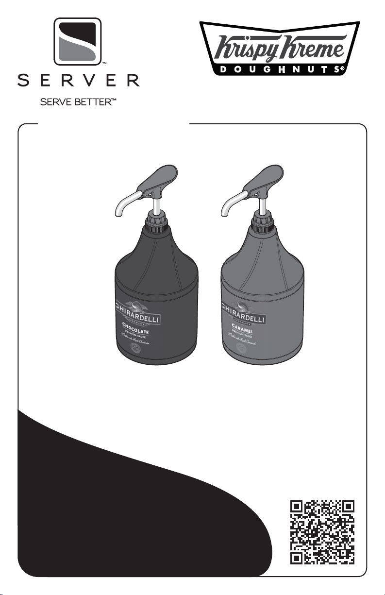
Thank You
...for purchasing your Maximo Sauce Dispensing
Unit. This efficient, environmentally-friendly system
delivers precise portions and is a reliable alternative to
the constant expense of disposable pumps.
CONSISTENT PORTIONS—SERVE BETTER
Server 87977
Server 87976
Ghirardelli Maximo
Sauce Dispensing
System Video
Directions:
Page 2
SAFETY
According to food and safety regulations, most
foods must be stored and/or served at certain
temperatures or they could become hazardous.
Check with local food and safety regulators for
specific guidelines.
Be aware of the product you are serving and the
temperature the product is required to maintain.
Server Products, Inc. cannot be responsible for the
serving of potentially hazardous product.
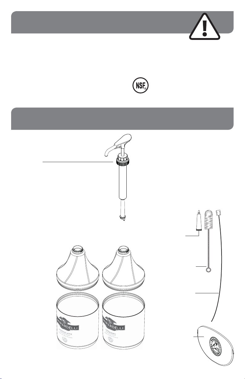
SYSTEM PARTS
Pumps are preset
to deliver correct
portions:
0.33 FL OZ PUMP
87986
0.50 FL OZ PUMP
87982
0.625 FL OZ PUMP
87991
IMPORTANT
Clean, rinse, sanitize, and dry parts daily or regularly
to comply with local sanitization requirements.
NSF International lists this pump as:
“Not acceptable for dispensing potentially
hazardous foods.”
Page 2
CHOCOLATE
LID
88352
CHOCOLATE
BASE
88376
CARAMEL
LID
88367
CARAMEL
BASE
88377
FOOD
EQUIPMENT
LUBRICANT
40179
11" BRUSH
82049
21" BRUSH
84257
SCRAPER
87022
Page 3
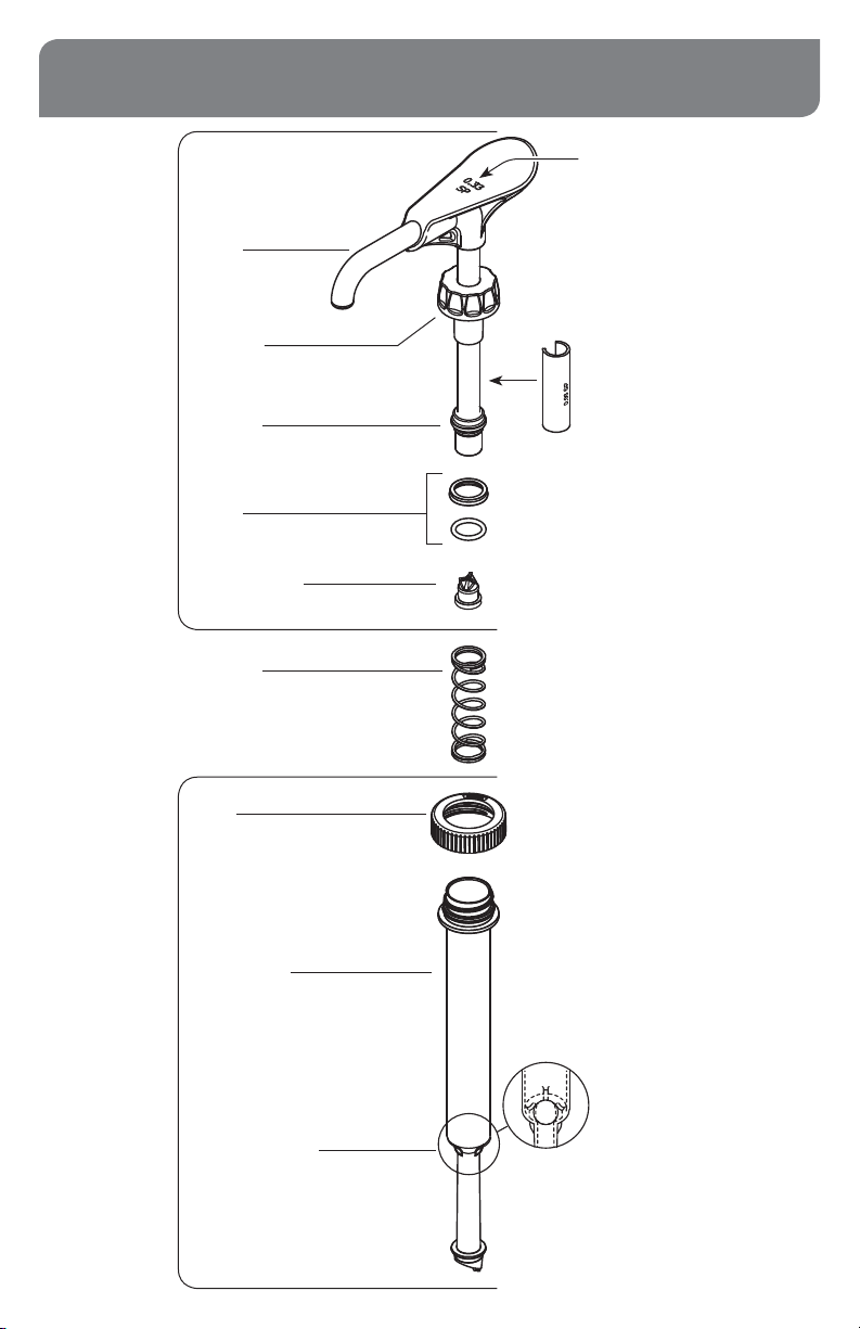
PUMP DETAILS FOR 87986, 87982, 87991
HEAD
ASSEMBLY
DISCHARGE
TUBE
LOCKING
COLLAR
PISTON
SEAL ASSEMBLY
(Seal & O-Ring)
83003
PINCH VALVE
88203
SPRING
88395
Portion size is marked on top.
Example: “0.33 SP”
indicates 0.33 fl oz Syrup Pump.
GAGING COLLAR
Collar snaps onto head assembly
to set proper portion size.
Portion size is marked on collar.
CYLINDER
ASSEMBLY
CAP
CYLINDER
88553
STAINLESS STEEL BALL
1/2" DIAMETER
06022
(Ball snaps inside cylinder and
can always remain installed.)
Page 3
Page 4
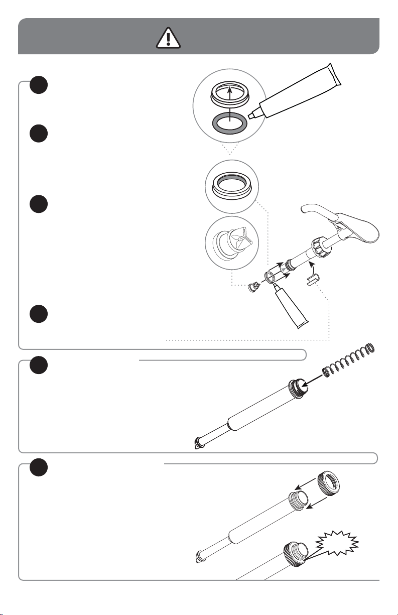
ASSEMBLY
INSTALL O-RING
1
into seal.
Apply food equipment lubricant on
O-ring
INSTALL SEAL
2
onto head assembly piston.
Apply small amount of food equipment
lubricant inside seal.
TIP: Flared end of seal should face
away from piston head.
INSTALL PINCH VALVE
3
Apply small amount of food equipment
lubricant inside bottom of piston.
TIP: Squeeze the pinch valve open
before installation to ensure it isn’t
stuck shut.
Install pinch valve into bottom of piston.
Rotate pinch valve to spread
lubricant evenly.
Press pinch valve securely to seal end.
INSTALL GAGING COLLAR
4
onto side of head assembly piston.
Portion size marked on gaging collar must match
portion size marked on top of pump.
PRACTICE SAFETY. WASH ALL PARTS
PROPERLY BEFORE USE.
See page 10.
5
6
Page 4
INSERT SPRING
INTO CYLINDER
SNAP CAP ONTO
CYLINDER
Press firmly to secure cap down
over all threading on cylinder.
SNAP!
Page 5

INSTALL HEAD ASSEMBLY
7
INTO CYLINDER
Apply a small amount of food equipment
lubricant to the outside of seal.
Slide locking collar down onto
cylinder threading.
Tighten firmly to secure head assembly
to cylinder.
Page 5
Page 6

ASSEMBLY
ATTACH PUMP TO LID
8
Screw pump cap onto lid threading
to secure.
ATTACH PUMP TO POUCH
9
• Place sauce pouch on countertop
with pouch fitment circle facing upward.
• Position pump connector directly
over center of pouch fitment.
• Press pump connector down
to pierce through film in pouch fitment.
• Pump connector is fully engaged when
top surface of pouch fitment touches
pump connector rim.
Continued from pages 4 & 5.
10
Page 6
INSERT PUMP, LID &
POUCH COMBINATION
INTO BASE
Loosely fold pouch around bottom
of pump while inserting into base.
Page 7

PUSH LID DOWN
11
onto base.
Snap into position to secure.
SNAP
PRIME PUMP
12
Press pump several times until sauce
is dispensed.
READY
MAXIMIZE POUCH EVACUATION
WHEN SAUCE POUCH SEEMS EMPTY
(AFTER PUMPING), USE POUCH SCRAPER.
REMOVE PUMP, LID &
1
POUCH COMBINATION
FROM BASE
STRETCH POUCH FLAT
2
on countertop.
USE SCRAPER
3
to push sauce towards pump and
maximize evacuation from pouch.
RETURN PUMP, LID &
4
POUCH FOR OPERATION
DISPENSE UNTIL ALL
5
REMAINING SAUCE
IS EVACUATED FROM
POUCH
Completely empty pouch may
be discarded.
Page 7
Page 8

UNIT TAKE-DOWN
REMOVE PUMP,
1
LID & POUCH
from shroud.
REMOVE POUCH
2
from pump.
Completely empty pouch
may be discarded.
3
4
Page 8
REMOVE PUMP
from lid. Loosen cap from
lid threads to release.
DISASSEMBLE & CLEAN PUMP
Page 9

PUMP DISASSEMBLY
DISASSEMBLE AND WASH
ALL PARTS PROPERLY BEFORE USE.
During disassembly, collect small parts
in a container to prevent loss.
SEPARATE CYLINDER
1
ASSEMBLY & HEAD
Loosen locking collar to release.
REMOVE SPRING & CAP
2
FROM CYLINDER
See page 10.
REMOVE PINCH VALVE
3
from head assembly.
Pinch gently and twist
to pull valve out.
REMOVE SEAL
4
from head assembly by pressing it
down and off with thumb.
Do not use a sharp tool.
REMOVE O-RING
5
FROM SEAL
6
REMOVE GAGING COLLAR
Page 9
Page 10

PUMP CLEANING
FLUSH & RINSE
1
all pump surfaces with hot water.
Place lower end of pump into container
of hot water and operate pump until all
remaining product is expelled and only hot
water is discharged.
DISASSEMBLE & CLEAN
2
all washable parts with soap and hot water
(See DISASSEMBLY on page 9.)
USE SUPPLIED BRUSH
to thoroughly clean inside discharge
tube and any confined areas.
RINSE
3
fully with clear water.
SANITIZE
4
all parts according to local sanitization
requirements. All parts in contact with food
must be sanitized.
AIR DRY
5
all parts fully.
YES!
Use dishwashing
soap, hot water
and nylon brush
Pump is dishwasher safe.
LID & BASE CLEANING
YES!
Use dishwashing
soap and hot water
to clean lid and base.
DO NOT IMMERSE BASE IN WATER
Page 10
• A general purpose, nonabrasive cleaner
may be used on hard to remove deposits.
• Do not use abrasive, caustic or ammonia
based cleansers.
• Do not use cleansing agents with high
concentrations of acid, alkaline or chlorine.
• Do not use metal scrapers or cleaning
pads that could scratch surfaces.
Page 11

CLEAN-IN-PLACE PROCEDURE FOR PUMPS
CLEAN
1
• Pump out all (if any) remaining food
product from inside pump body.
• Wash and rinse off outside of pump body.
• Flush out and rinse inside of pump.
• Place lower end of pump into container
full of water and operate pump until all (if
any) remaining product is expelled
and only warm water flows from discharge
tube.
• Mix 1 tsp (5 mL) of dishwashing detergent
with 1 quart (.95 L) of hot tap water
(approximately 110°F/43°C).
• Place lower end of pump into cleaning
mixture. Pump until all cleaning mixture is
expelled.
RINSE
2
• Place lower end of pump into 2 cups
(.5 L) of hot tap water (approximately
110°F/43°C) and pump until all tap
water is expelled.
SANITIZE
3
• Mix one 1 oz (30 mL) packet of KAY-5
Sanitizer/Cleaner (EPA REG No. 5389-
15) with 2.5 gallons (9.5 L) of tap water
(approximately room temperature).
• Place lower end of pump into this
sanitizing mixture and repeatedly operate
pump until 1 quart (.95 L) sanitizing
mixture is pumped through pump.
RINSE
4
• Place lower end of pump into 1 cup
(.24 L) of hot tap water (approximately
110°F/43°C) and pump until all tap
water is expelled.
CARE OF STAINLESS STEEL
This durable pump includes
stainless steel components.
If you notice corrosion beginning on any
stainless steel surface, you may need to change
the cleansing agent, sanitizing agent, or the
cleaning procedures you are using.
• A mildly abrasive nylon or brass brush may
be used to remove any stubborn deposits.
• Fully rinsing and drying all parts can help
prevent corrosion. Elements and minerals in
tap water can accumulate on stainless steel
parts and create corrosion.
• Do not use abrasive, caustic or ammonia
based cleansers.
• Do not use products containing acids,
alkalines, chlorine, or salt. These agents can
corrode stainless steel.
• Do not use metal scrapers or cleaning pads
that could scratch surfaces.
Page 11
Page 12

TROUBLESHOOTING
PRODUCT OOZES OUT FROM LOCKING COLLAR?
• Ensure that the cap is securely snapped
into place below all the threading on
the cylinder.
INCONSISTENT PORTIONS?
• Clean pump.
• Ensure product container is not empty
and has enough product to pump.
• Ensure unit is
assembled correctly.
TIP: Seal has a slight taper.
Install with flat side towards
top, flared side down.
• Ensure pinch valve is
installed correctly.
TIP: Squeeze the pinch valve
open before installation to
ensure it isn’t stuck shut.
• Ensure that the spring is functional.
Replace broken spring if necessary.
• Ensure that the stainless steel ball
is snapped in place below tabs.
SNAP!
SERVER PRODUCTS
LIMITED WARRANTY
Server Products equipment is backed by a
two-year limited warranty against defects in
materials and workmanship.
For complete warranty information go to:
www.Server-Products.com
NEED HELP?
Server Products Inc.
3601 Pleasant Hill Road
Richfield, WI 53076 USA
262.628.5600 | 800.558.8722
SPSALES@SERVER-PRODUCTS.COM
Page 12
GENERAL SERVICE,
REPAIR OR RETURNS
Before sending any item to Server Products
for service, repair, or return, contact Server
Products customer service to request a Return
Authorization Number. Merchandise must be
sent to Server Products with this number. Service
is extremely prompt. Typically, units are repaired
and ship out within 48 hours of receipt.
Merchandise being returned for credit must be in
new and unused condition and not more than 90
days old and will be subject to a 20% restocking
charge.
Please be prepared with your Series Number
and Description located on the unit.
Please refer to pages 2 & 3 for individual
Part Numbers.
Manual 01932-RevB 020518
 Loading...