

Page 1
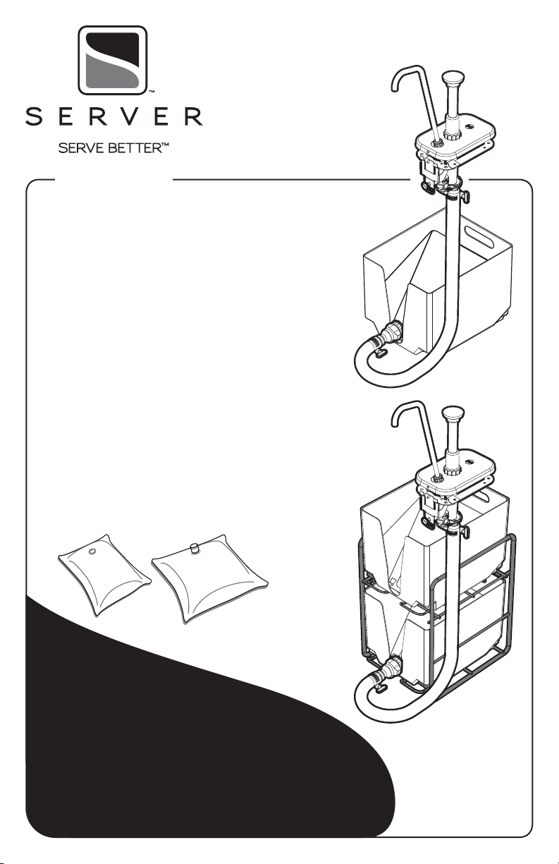
Remote
Dispensing System
Remote Pump with 36" Hose
SINGLE POUCH SYSTEM
85783
Remote Pump with 36" Hose
TWIN POUCH SYSTEM
85784
Use with pouches up to 3 gallons
with either 16mm fitment
or 38mm connector.
Thank You
...for purchasing our Remote Dispensing System.
This manually operated system simplifies
high-volume dispensing, eliminating the
hassle of a CO
HIGH VOLUME—HIGHLY CONVENIENT
driven dispenser.
2
Page 2
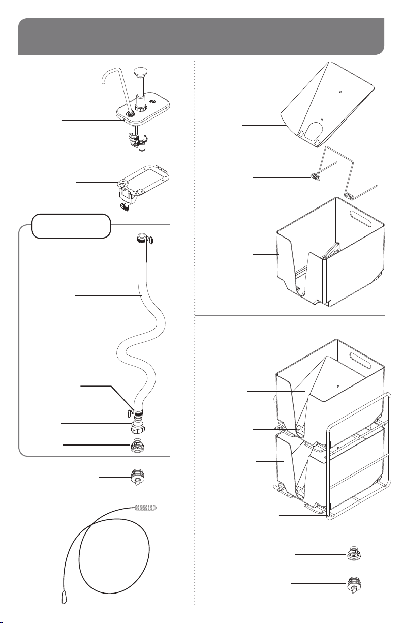
REMOTE SYSTEM PARTS
SINGLE POUCH
SYSTEM
85783
PUMP
85951
MOUNTING
BRACKET
85791
HOSE ASSEMBLY
85758
36" HOSE
85255
TURN-KEY
CLAMPS (2)
85877
EVACUATION
PLATE
07814
TORSION
SPRING
07813
POUCH
SUPPORT
07811
TWIN POUCH
SYSTEM
85784
(2) EVACUATION
PLATES
07814
COUPLING
85753
DISPENSING CAP
85754
16MM ADAPTER
85264
52" BRUSH
85206
Page 2
(2) TORSION
SPRINGS
07813
(2) POUCH
SUPPORTS
07811
WIREWISE RACK
88643
Twin system includes
(2) DISPENSING CAPS
85754
&
(2) 16MM ADAPTERS
85264
Page 3
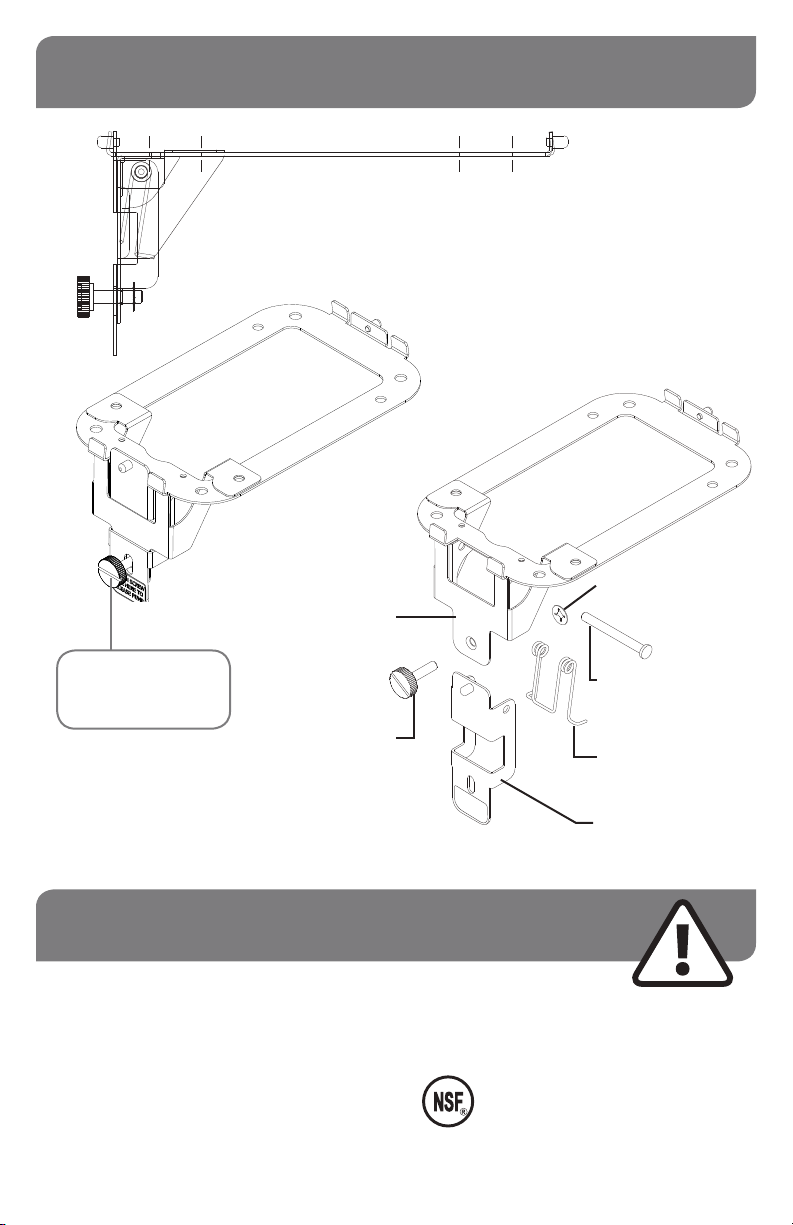
MOUNTING BRACKET DETAILS
MOUNTING BRACKET
85791
Side View
Assembled View
#10 PUSHNUT
86676
LATCH
ASSEMBLY
PLATE
Tighten or Loosen
Thumb Screw to
Lock or Release Lever
85787
THUMB
SCREW,
10-32 X 3/4
86691
LOOSEN SCREW
PULL HERE TO
RELEASE PUMP
COTTERLESS HINGE PIN
81105
TORSION SPRING
85395
LEVER ASSEMBLY
85789
SAFETY
According to food and safety regulations,
most foods must be stored and/or served at
certain temperatures or they could become
hazardous. Check with local food and safety
regulators for specific guidelines.
Be aware of the product you are serving
and the temperature the product is required
to maintain. Server Products, Inc. cannot
be responsible for the serving of potentially
hazardous product.
IMPORTANT
Clean, rinse, sanitize, and dry parts daily or regularly
to comply with local sanitization requirements.
NSF International lists this pump as:
“Not acceptable for dispensing potentially
hazardous foods.”
Page 3
Page 4

QUICK START
INSTALL THE COUNTERTOP BRACKET
1
• Choose a location with easy access and
convenient height for pump.
• Allow room for slack in hose during set-up,
pouch replacement and take-down.
IMPORTANT
TIP:
Do not locate
countertop
hole directly
above pouch
support(s).
Offset the hole
to leave space
for pump and
hose below.
INSERT THE PUMP INTO BRACKET
2
Always clean pump first.
Refer to separate instructions for the pump.
• Insert pin on rear of bracket into hole on
rear of lid.
•
Pull the under-counter lever forward to allow
front pin of bracket into front hole of lid.
• Release lever to secure front bracket pin.
• Tighten thumbscrew to lock lever.
YOU WILL NEED:
• A qualified person to install the countertop bracket
• Screwdriver, (4) screws, router and/or saw equipment
• Use cutout template included to mark,
cut and drill holes.
• Secure the bracket with four screws.
3
Page 4
ATTACH HOSE TO PUMP
• Slide hose onto valve connector at bottom
end of pump.
• Rotate hose clamp turn-key clockwise to
secure hose.
TIP: Hose may be trimmed
if length is excessive.
Page 5

PREPARE POUCH(ES)
4
Place condiment pouch on flat surface with pouch connector or fitment facing upward.
If pouch has
38MM EXTERNAL CONNECTOR
• Remove pouch cap.
• Screw dispensing cap onto connector.
PLACE POUCH(ES)
5
INTO POUCH SUPPORT(S)
Locate dispensing cap in front slot directed
downward for best evacuation of condiment.
If pouch has
16MM INTERNAL FITMENT
• Screw dispensing cap onto adapter.
• Position adapter directly
over center of pouch fitment.
• Press adapter down to pierce
through film in pouch fitment.
Pump is fully engaged when
top surface of pouch fitment
touches adapter rim.
PLACE SUPPORT(S)
6
BENEATH COUNTER
Twin pouch system includes
wire rack for pouch supports.
CONNECT HOSE TO POUCH
7
Snap hose end onto dispensing cap.
PRIME PUMP
8
Repeatedly press pump knob until condiment
is drawn up from pouch and hose below.
Page 5
Page 6

SWITCHING POUCHES
WHEN A CONDIMENT POUCH BECOMES EMPTY...
DISCONNECT HOSE
1
FROM EMPTY POUCH
Press button on side of hose coupling to release.
SNAP HOSE COUPLING ONTO
2
DISPENSING CAP ON NEW POUCH
See page 5 for how to prepare pouch(es).
Page 6
DID YOU KNOW?
The hose coupler and dispensing cap
prevent leaks when hose is disconnected.
Page 7

DISASSEMBLY
DISCONNECT HOSE FROM PUMP
1
Turn hose clamp turn-key counter-clockwise
to loosen the hose.
DISCONNECT HOSE FROM
2
POUCH
Press button on side of hose coupling to release.
REMOVE PARTS(S) FROM POUCH
3
Unscrew dispensing cap from pouch.
IF USED: Remove adapter from 16mm pouch fitment.
IMPORTANT: Only throw away empty pouch.
Keep any dispensing cap and adapter fitment.
REMOVE PUMP FROM COUNTER
4
BRACKET
• Loosen thumbscrew on bracket.
• Pull lever under counter to release front hole
of lid from front pin of bracket.
• Lift pump free from pin in back of bracket.
Page 7
Page 8

CLEANING
Refer to separate instruction manual
for pump cleaning.
CLEAN
1
After disassembling, thoroughly clean all
washable parts with soap and hot water.
RINSE fully with clear water.
2
SANITIZE
3
all parts according to local sanitization
requirements. All parts in contact with
food must be sanitized.
4
AIR DRY all parts fully.
YES!
Use dishwashing
soap and hot water.
Use supplied brush to clean inside hose.
• External surfaces may be wiped clean
with a clean damp cloth.
• Glass and surface cleaners approved for
use in food contact areas may be used.
• Do not use abrasive, caustic or ammonia
based cleansers.
• Do not use metal scrapers or cleaning
pads that could scratch surfaces.
SERVER PRODUCTS
LIMITED WARRANTY
Server Products equipment is backed by a
two-year limited warranty against defects in
materials and workmanship.
For complete warranty information go to:
www.Server-Products.com
NEED HELP?
Server Products Inc.
3601 Pleasant Hill Road
Richfield, WI 53076 USA
262.628.5600 | 800.558.8722
SPSALES@SERVER-PRODUCTS.COM
Page 8
GENERAL SERVICE,
REPAIR OR RETURNS
Before sending any item to Server Products
for service, repair, or return, contact Server
Products customer service to request a Return
Authorization Number. Merchandise must be
sent to Server Products with this number. Service
is extremely prompt. Typically, units are repaired
and ship out within 48 hours.
Merchandise being returned for credit must be in
new and unused condition and not more than 90
days old and will be subject to a 20% restocking
charge.
Please be prepared with your Part Numbers,
as shown on pages 2 & 3.
Manual 01898-RevC.indd 121917
Page 9

3.000 C-C REF (NEW PATTERN)
3.500 C-C REF (EXISTING HOLES)
ACCESS END
4.000 C-C REF (EXISTING HOLES)
5.625 C-C REF (NEW PATTERN)
3.000 C-C TYP
.31
6.00
2.50
MOUNTING HOLE PATTERN
5.625 C-C TYP
CUTOUT TeMPLATe
Full Scale 1:1
 Loading...