

Page 1

NG012200 Under Counter Refrigerator
Owner’s Manual
Page 2

FOR YOUR SAFTEY
DO NOT STORE OR USE GASOLINE OR
OTHER FLAMMABLE VAPORS OR LIQUIDS IN
THE VICINITY OF THIS OR ANY OTHER
APPLIANCE.
WARNING: IMPROPER INSTALLATION,
ADJUSTMENT, ALTERATION, OR
MAINTENANCE CAN CAUSE INJURY OR
DEATH. READ THE INSTALLATION,
OPERATION AND MAINTENANCE
INSTRUCTIONS THOROUGHLY BEFORE
INSTALLING OR SERVICING THIS
EQUIPMENT.
KEEP THIS MANUAL IN A SAFE
PLACE AND RETAIN FOR FUTURE
USE
2
Page 3

Owner’s Manual
Sertek Under Counter Refrigerator
Supplier Name:
Address:
Serial #:
Date Received:
Date Installed:
Telephone #:
Fax#:
Service Warranty NSC #:
Sertek LLC
6399 Shier Rings Rd
Dublin, OH 43016
______________________
______________________
______________________
614-504-5828
614-504-5728
877-277-7221
Product Description
The NGK Under Counter Refrigerator MG3 Model NG012200 has been built to fit
into Wendy’s NGK front counter assemblies. It features two drawers for holding
packaged product.
3
Page 4

Table of Contents
Replacement Parts List 5-7
Daily Maintenance 8
Monthly Maintenance 9
Servicing the Condensing Unit 10
Servicing the Evaporator 11-12
Troubleshooting Guide 13
MR4PMUHV Temperature/Defrost Control Quick Reference Guide 14-15
MR4PMUHV Display Code Chart 16
Electrical Schematics 17
Service Chart 18-19
4
Page 5

Replacement Parts List
1
4 5
7
2 3
6
8
9
5
Page 6

Refrigeration Unit
10
13 14
16
11 12
15
6
Page 7
List of Replacement Parts
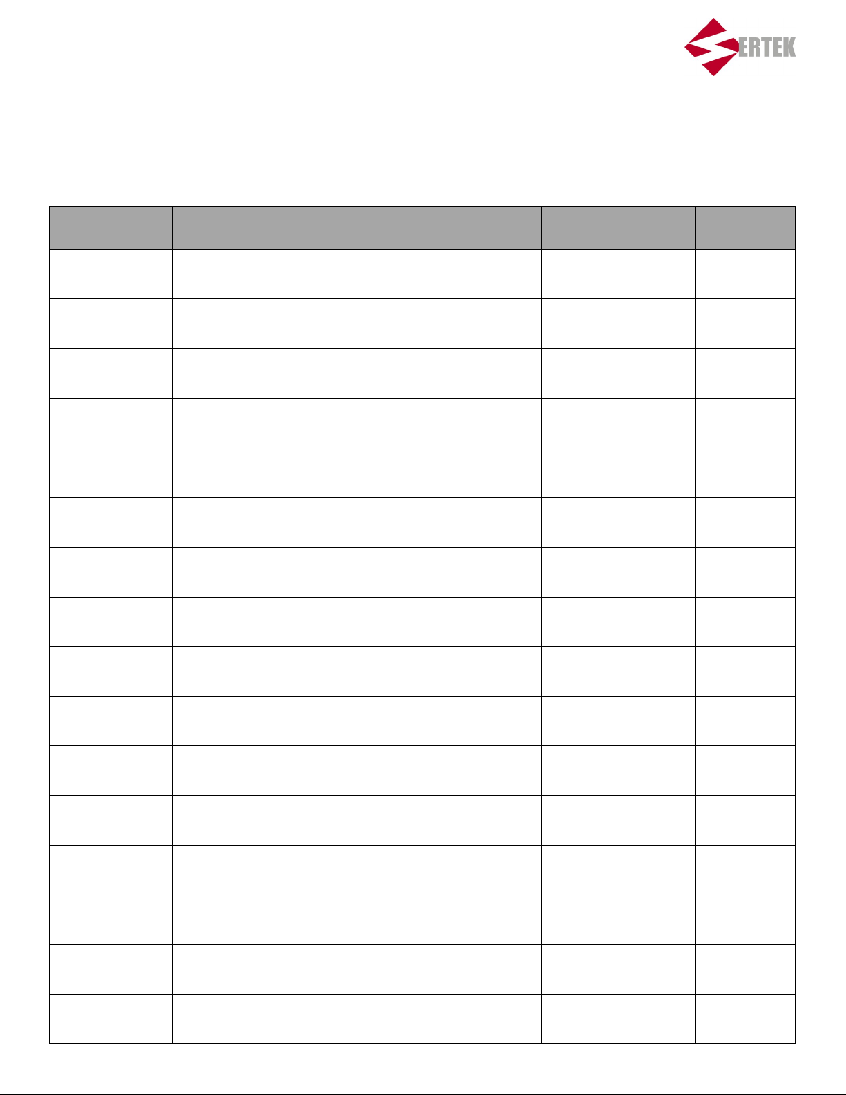
LIST ID # DESCRIPTION PART # QTY
1 Under Counter Refrigerator NG012200 1
2 Drawer Gasket 07000272-25 2
3 Drawer Front NG012200-200-DF 2
4 Heavy Duty Drawer Slide (Bottom) 7000486-550 2
5 Heavy Duty Drawer Slide (Top) 7000486-300-CLOSED 2
6 Top Drawer Pan 0902616 1
7 Top Drawer Insert NG012260 1
8 Bottom Drawer Insert NG012265 1
9 Bottom Drawer Pan 0902588 1
10 Ranco High Pressure Control 7000009 1
11 Component Hardware Condensate Evaporator Pan 7000023-72 1
12 Orion Axial Fan 7000291-OYL 2
13 Copeland Condensing Unit 7000025 1
14 Johnson Controls Temperature Controller RU010103 1
15 HeatCraft Evaporator Coil 7000836 1
16 Emerson Expansion Valve 7000113 1
7
Page 8
Daily Maintenance
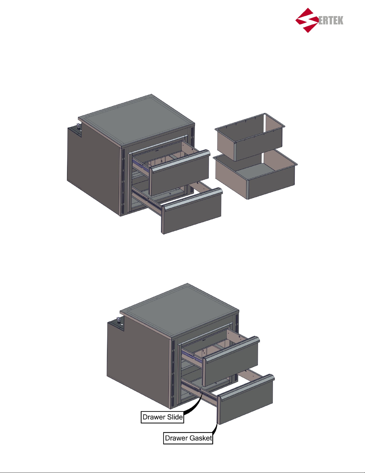
1. Remove the two pans to be cleaned at the store’s dish tank.
2. Inspect the unit’s drawer gaskets and slides. Ensure that there is no food build up and that both the
drawer slide and gasket are functioning properly.
8
Page 9
Monthly Maintenance
1. Perform Daily Maintenance.
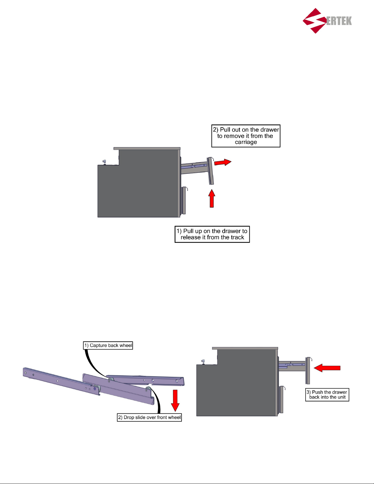
2. Remove the unit’s drawer slides and clean the storage bay.
I. Follow the steps below to remove the drawer slides from the unit.
II. With the drawer slides removed there is clear access to the storage bay. Use a damp cloth
and Wendy’s approved cleaner to thoroughly wipe down the interior of the unit.
III. Once the bay is cleaned replace the drawer slides following the steps shown below.
9
Page 10
Servicing the Condensing Unit
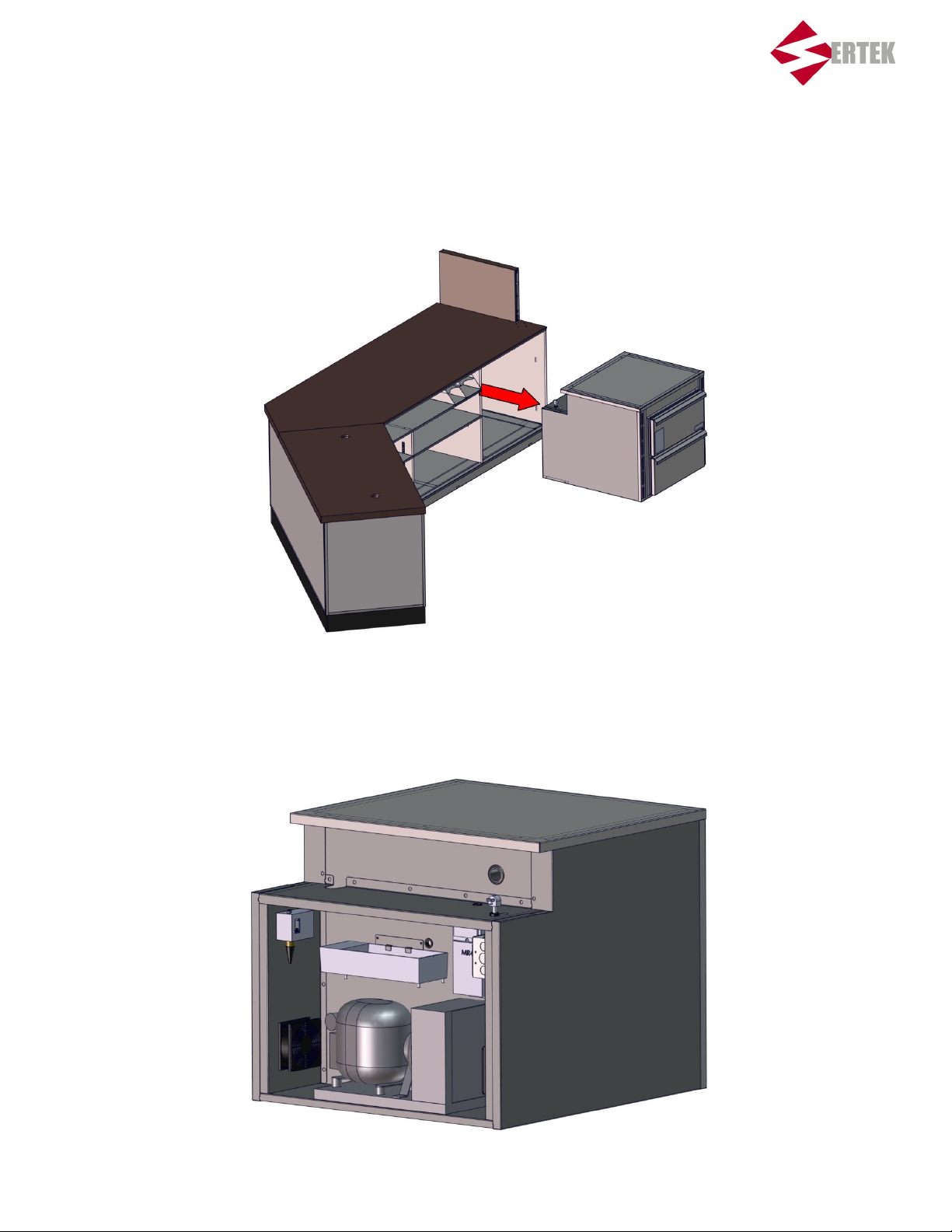
1. Remove the unit from it’s housing in the Front Counter.
2. The condensing unit, temperature control, high pressure switch, axial fans, and condensate
evaporator pan can be accessed from the back of the unit.
10
Page 11
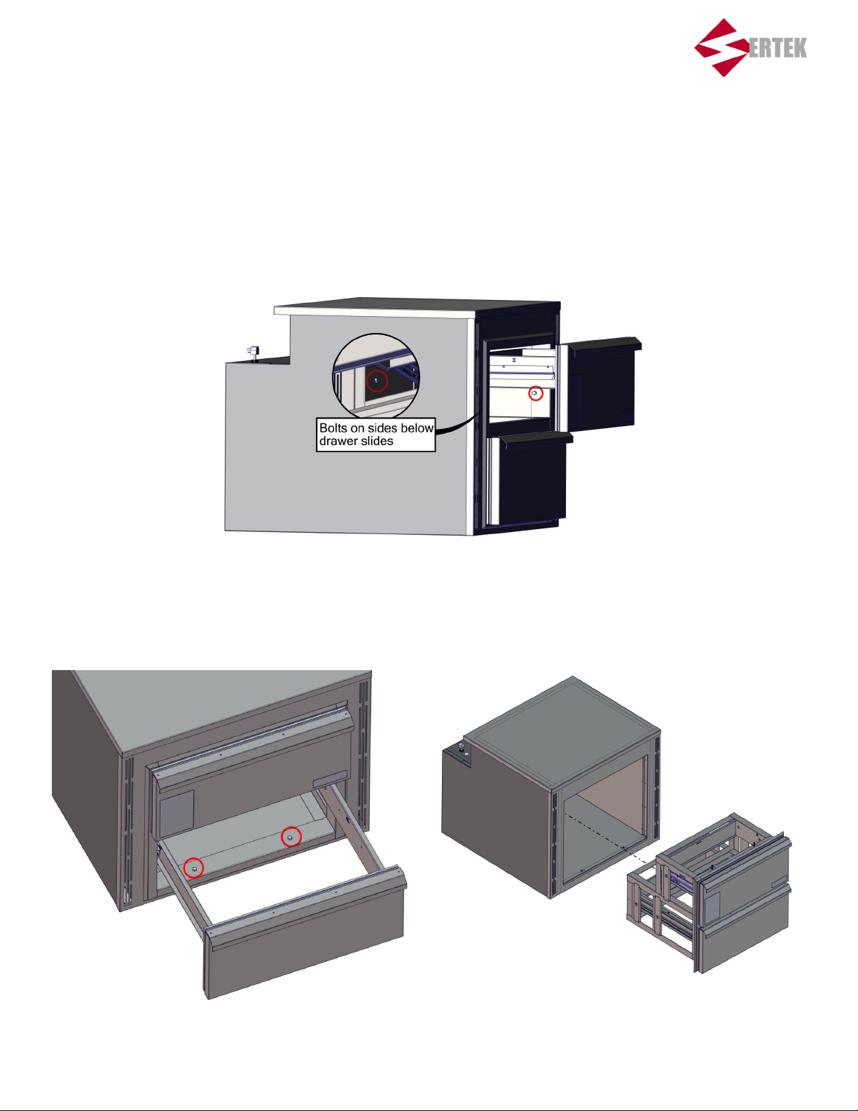
Servicing the Evaporator
1. In order to reach the evaporators and expansion valve complete access to the cooler bay will be needed. To
accomplish this you will need to remove the drawer assembly insert. First remove all the pans from the
drawer slides. Next remove the four 7/16” bolts securing the inserts to the cooler bay. The locations of these
bolts are shown below
2. Remove the two 7/16th bolts from the bottom and the drawer carriage can be pulled from the front of the
unit.
11
Page 12
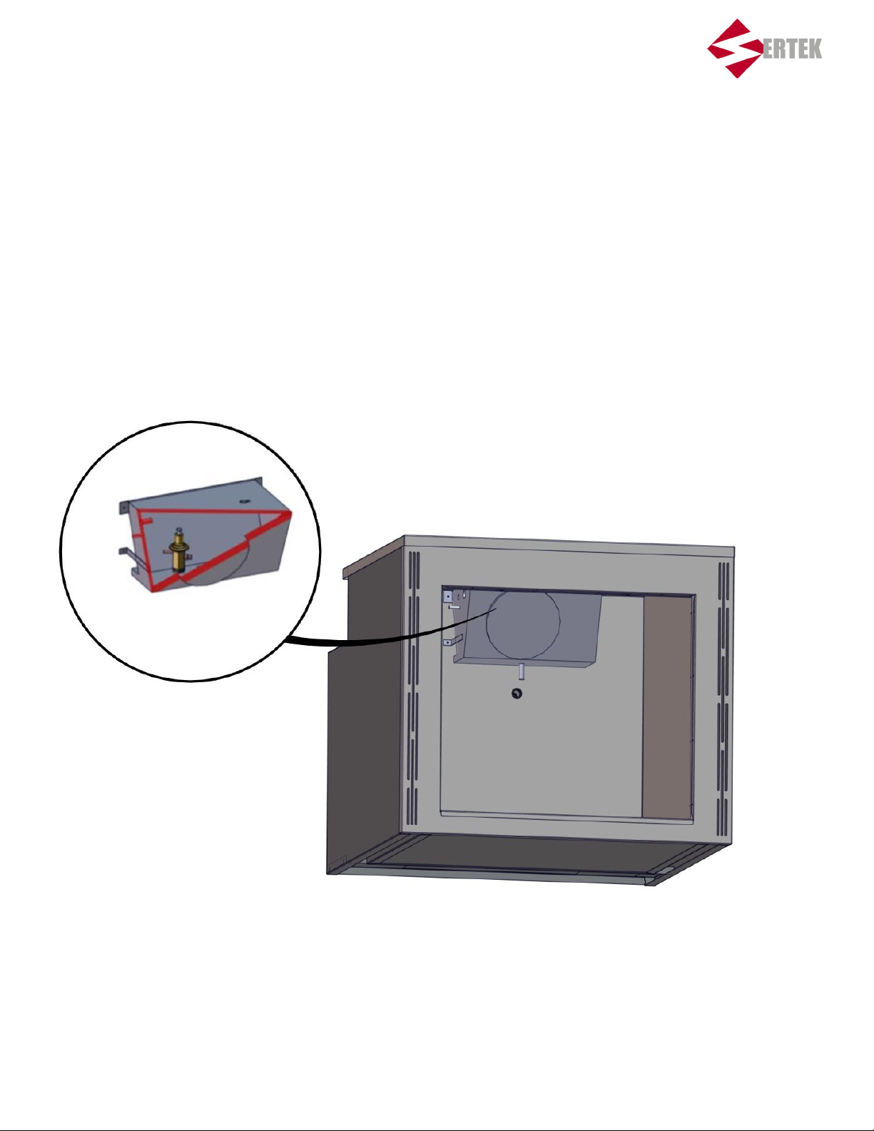
Servicing the Evaporator
3. Once the drawer carriage is removed there is clear access to the evaporator. To open the evaporator casing
and access the coil and expansion valve, remove the four 1/4” hex head screws holding the cover in place.
12
Page 13

Troubleshooting Guide
Problem Possible Cause Solution
UNIT WILL NOT RUN Breakers could be turned off.
Partial electrical power to the
building.
Unit is unplugged
THE FANS INSIDE OF THE
REFRIGERATION BOX ARE
RUNNING BUT IT IS NOT
KEEPING THE PRODUCT AT
THE PROPER TEMPERATURE
Condensing coil for the
compressor condensing unit
may be plugged up not allowing
enough air to pass through the
coil causing the unit to
overheat.
The high pressure control high
pressure switch may have
tripped, causing the condensing
unit to shut down.
Turn the breakers off and back
on to see if the unit comes on.
Ensure the unit is plugged into
the receptacle on the front
counter
Check to make sure other
equipment is working. If so and
the Under Counter Refrigerator
is not running call the NSC
service line. (877-277-7221)
If you are experiencing
problems with other equipment
as well call your maintenance
provider.
Check the store’s main breaker
box to ensure the proper
breakers are turned on.
Turn the unit off for approxi-
mately 15 minutes to allow time
for the unit to cool down.
Ensure that all fans are
operating correctly and there is
nothing blocking the intake on
the front of the unit. After 15
minutes have elapsed turn the
unit back on and wait for it to
reach temperature.
13
If all the breaker switches are
turned on and the Under
Counter Refrigerator is not
running call the NSC service
line. (877-277-7221)
Page 14
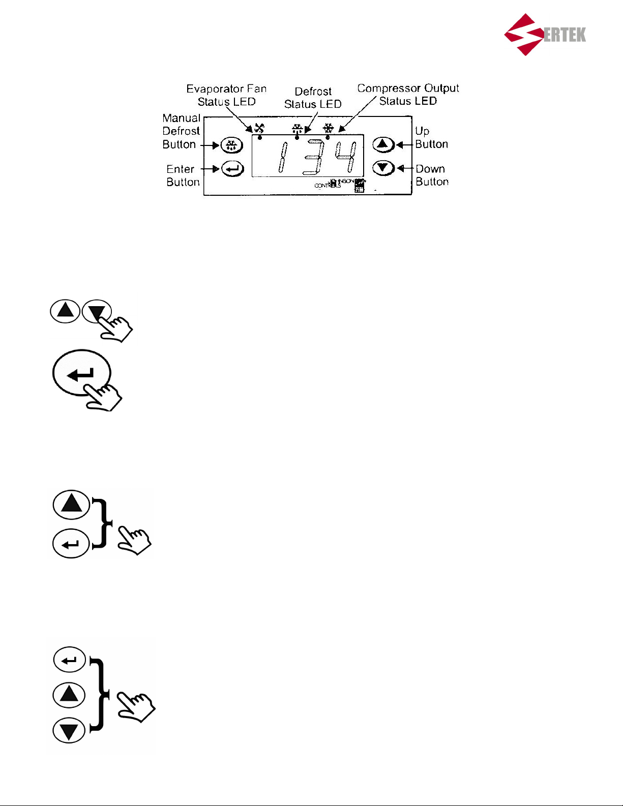
MR4PMUHV Temperature/Defrost Control Quick Reference Guide
Using the control module
During normal operation, the display shows the main sensor temperature.
Press up or down to scroll through the main sensor temperature, evaporator
sensor temperature, and the binary input status.
Press and hold enter for approximately three seconds to view the set point.
Note: After 15 seconds of inactivity, the display shows the main temperature.
Initiating a manual deep freeze
1. In sequence, press and hold enter then up.
2. Hold both buttons for five seconds.
3. The compressor output status LED lights and compressor contacts
close.
Unlocking or locking access to programming
1. In sequence, press and hold enter, up, and then down.
2. Hold all three buttons until ——— is displayed.
3. Continue holding until the sensed temperature is displayed
(approximately ten seconds).
14
Page 15
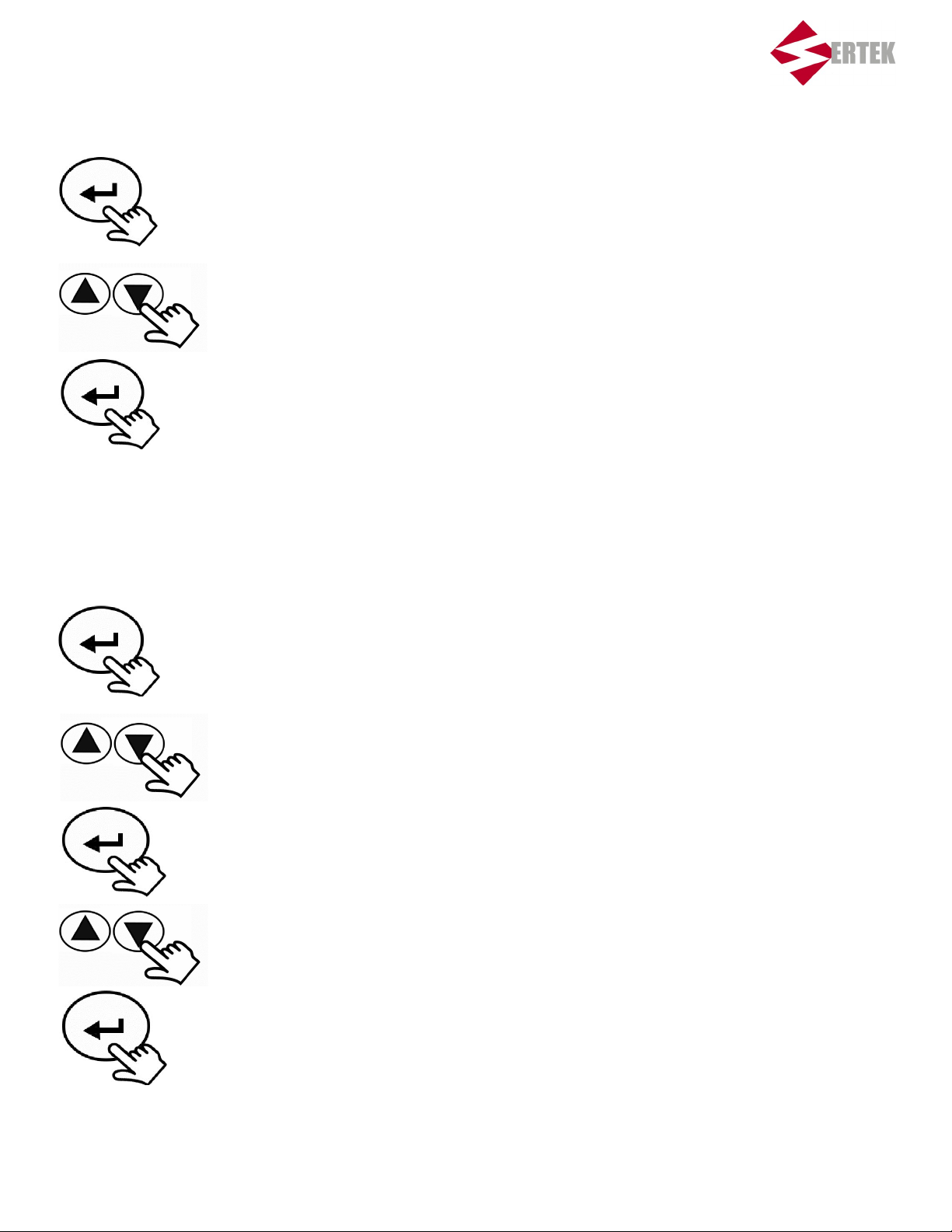
MR4PMUHV Temperature/Defrost Control Quick Reference Guide
Changing the set point
1. Press and hold enter for approximately three seconds.
2. Release enter when the set point value is displayed.
3. Press up or down to display the new set point value.
4. Press enter to save the new set point value.
Note: if enter is not pressed, the new set point value is not saved, and control reverts to
the previous set point value.
Changing other function settings
1. Press and hold enter for approximately 10 seconds.
2. The display code for differential is displayed (HY).
3. Press up or down until the display code for the desired function is
displayed (see freezer settings list).
4. Press enter. The functions existing value is displayed.
5. Press up or down until the desired setting value is displayed.
6. Press enter to save the new value. After 10 seconds of inactivity the,
display returns to normal operation.
Note: If enter is not pressed, the new value is not saved and reverts to the previous
saved value.
15
Page 16
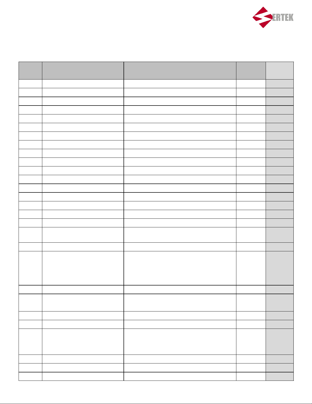
MR4PMUHV Display Code Chart
Display
Code Function Setting Range
(None) Setpoint -40° 99°F (-40° to 37°C) 35(°F)*
HY Differential 1° to 9°F (-17°to -13° C) 5(°F) 2(°F)*
LL Low Setpoint Stop -40°F (-40°C) to High Setpoint Stop -25(°F) 32(°F)*
HL High Setpoint Stop Low Setpoint Stop to 99°F (37°C) 40(°F) 36(°F)*
CC Cycle Delay 0 to 9 min 1 min 1 min
Co Deep Freezing Time 0 to 99 min 60 min 60 min
AH High Temperature Alarm 0 to 50°F (-17 to 10°C) 10(°F) 5(°F)*
AL Low Temperature Alarm -50° to 0°F (-45° to -18°C) -10(°F) -5(°F)*
Ad Alarm Differential 1° to 9°F (-17° to -13°C) 5(°F) 5(°F)
At Alarm Time Delay 0 to 99 min 3 min 3 min
dF Defrost Mode 0=Electric Defrost / 1 = Hot Gas Defrost 0 0
dE Defrost Termination Mode 0 = Time Based / 1 = Temperature Based 1 1
dt Defrost Termination Temperature 32° to 68°F (0 to 20°C) 55(°F) 44(°F)*
di Defrost Interval 1 to 99 hours 7 hours 6 hours*
dd Maximum Defrost Duration 0 to 99 min 45 min 45 min
Factory-Set
Value
Cooler
Settings
dC Dripping Time 0 to 99 min 5 min 5 min
dU First Defrost Delay OF (Off), 0 to 99 min OF (OFF) OF (OFF)
dP Display During Defrost 0 = Last Main Sensor Reading / 1 = Main Setpoint 0 0
dr Display Delay After Defrost 1 to 99 min 20 min 20 min
iF Binary Input Mode 0 = No Response 0 0
1 = Compressor Off
2 = Alarm On
3 = Evaporator Fan Off, Alarm On
id Binary Input Time Delay 0 to 99 min 0 min 0 min
FF Fan Operating Mode 0 = Parallel with Compressor 0 1*
1 = Always On
Fd Fan Startup Delay 0 to 99 min 5 min 0 min*
Fr Fan Start Temperature -22° to 41° F (-30 to 5°C) 40(°F) 40(°F)
SF Sensor Failure Operation 0 = Compressor on 2 2
1 = Compressor Off
2 = Based on Last 4 Cycles
So Temperature Sensor Offset -20° to 20°F (-29° to -6° C) 0(F°) 0(°F)
Un Temperature Units Used 0 = °C / 1 = °F 1 1
PU Display Refresh Rate 1 to 99 sec 1 sec 1 sec
16
Page 17
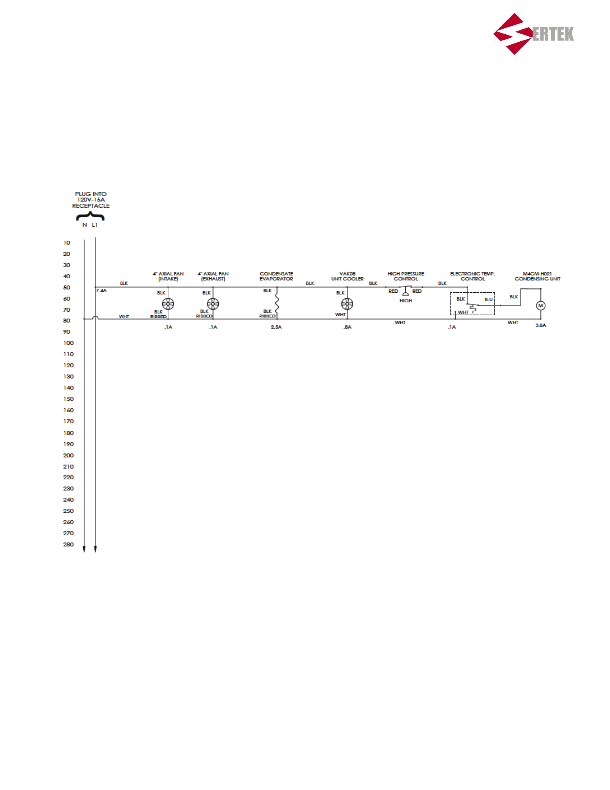
Electrical Schematics
17
Page 18
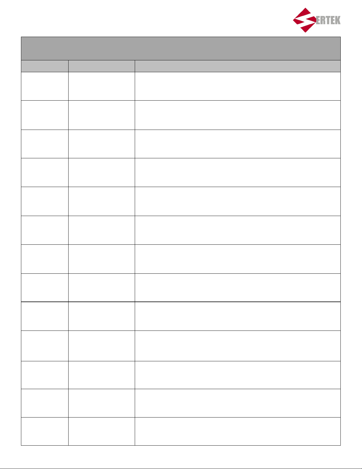
NG015000 Service Chart
Service Date Serviced By Service Provided
18
Page 19
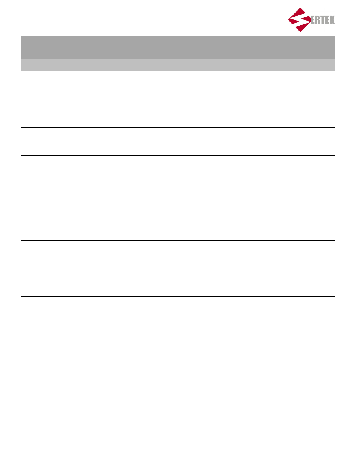
NG015000 Service Chart
Service Date Serviced By Service Provided
19
Page 20

NGK UNDER COUNTER REFRIGERATOR
MODEL NG012200
OWNER’S MANUAL
7NG012200-MNL1.1015
3/9/16 RS
 Loading...