

Serpent Model Racing Cars BV SPYDER SRX2 MH Instruction Manual


INTRODUCTION
Thank you very much for selecting this Serpent rc car and thus become a member of the ever growing
worldwide Serpent racing family. Serpent started in 1980 and has been growing its product-line and fan
-base ever since.
The Serpent Spyder SRX2 MH is a state of the art 1/10 scale 2wd buggy which will give you the true Serpent
racing experience. The assembly manual will guide you through all the steps to complete the car, so you
can hit the track with a good base-set-up soonest. The Serpent design department succeeded to create a
superbly performing car combined with eas of assembly and maintenance. The high quality standards of
all parts and hardware will make racing your Serpent car a very rewarding activity!
The Spyder SRX2 MH kit includes 2 types of transmissions and each has its own manual. Use the LMT (
low-medium-traction) for the 3-gear standing transmission, and the MHT ( medium-high-traction) for the
3-gear laydown transmission. Carefully follow the A,B, C bag-numbering in the steps which apply to the
transmissions.
Through our team, website and social media we will keep you up-to-date on all developments of the Serpent
cars. We hope to meet you on the track and through our various media! Enjoy the drive!
Team Serpent
Multiple World Champions
INSTRUCTIONS
Serpent’s long tradition of excellence extends to the instruction manuals, and this instruction manual is no
exception. The easy-to-follow layout is richly illustrated with 3D-rendered full-color images to make your
building experience quick and easy. Following the instructions will result in a well-built, high-performance
race-car that will soon be able to unleash its full potential at the racetrack. The kit includes bags, with
bagnumbers, which refer to the same step in the manual. Open only the indicated bag(s) per step and nish
that part of the assembly. Remaining parts will be needed lateron in the assembly process.
plaSTIC paRTS
The Serpent moulded parts are very durable and hard. When assembling longer screws in new composite
parts, make sure to use new hex bits in your (power) tools. Pre-threading also helps to avoid screw damage.
SETUp
In certain assembly steps you need to make basic adjustments, which will give you a good initial setup
for your Serpent Spyder SRX2 MH. Fine-tuning the initial setup is an essential part of building a highperformance racecar like your Serpent Spyder SRX2 MH.
EXplODED VIEWS aND paRTS lIST
The exploded views and parts lists for the Serpent Spyder SRX2 MH are presented in the Reference Guide
section in the back of this manual. The exploded views show all the parts of a particular assembly step
along with the Serpent part number and hotlink to the Serpent website. Partnumbers in orange indicates
that this part is an optional. Optionals part names and numbers are showed below.
CUSTOmER SERVICE
Serpent has made a strong effort to make this manual as complete and clear as possible. Additional info
may be published in our website: www.serpent.com or you may ask your dealer or the Serpent distributor
for advice, or email Serpent direct: info@serpent.com. The Serpent Facebook, Twitter and Youtube pages
give additional means of support and communications.
SafETy
Read and take note of the ‘Read this First section’ before proceeding to assemble the car-kit. This car-kit is
intended for persons aged 16 or older.
REaD ThIS fIRST!
- This is a highly technical hobby product, intended to be used in a safe racing environment. This car
is capable of speeds in excess of 80 km/h or 50mph. Please follow these guidelines when building and
operating this model.
- Parental guidance is required when the builder/user of this car is under 16.
- Follow the building instructions. If in doubt, contact your dealer or importer.
- Be sure to use the proper tools when assembling the car. Always exercise caution when using electric
tools, knives and other sharp objects.
- Be careful when using liquids like lubrication oil, fuel or glue. Do not swallow.
- Follow the manufacturer’s instruction in case you experience irritation after using the product.
- Be careful when operating the car. Stay away from any rotating parts such as wheels, gears and
transmission. Stay away from motor, engine and exhaust pipe system or speedo during and immediately
after use, as these parts may be very hot. We advise to use protective hand cloves.
- Only operate this car in a safe environment, like a special racing track or a closed parking lot. Avoid using
this car on public roads, crowded places or near infants.
- Before operating this car, always check the mechanical status of the car. Also check that the transmitter
and receiver frequencies correspond and are not used by any other racer at the same time. Check that the
batteries of the transmitter and receiver- are fully charged.
- After use, always check all the mechanics of the car. We advise to clean the car immediately after use,
and inspect the parts for wear or fractures. Replace when necessary. Do not use water, methanol, thinner
or other solvents to clean the car.
- Empty the fuel tank (depending on model) if needed and disconnect the receiver battery.
- Store the car in a dry and heated place to avoid corrosion of metal parts.
- Avoid using this car in wet conditions as the water will cause corrosion on the metal parts and bearings
and these parts will cease to function properly. If driven in the wet, ensure that all the electric equipment is
waterproofed and after use, that all moving parts are dried immediately.
CONTENTS
•
CHASSISASSEMBLY 4
•
STEERINGASSEMBLYASSEMBLY 5
•
FRONTASSEMBLY7
•
REA RASS EMBLY 11
•
DIFFASSEMBLY15
•
TRANSMISSIONASSEMBLY 17
•
SHOCKSASSEMBLY 27
•
FINALASSEMBLY30
•
EXPLODEDVIEWS34
•
TEA MSER PENT NET WORK 44
3
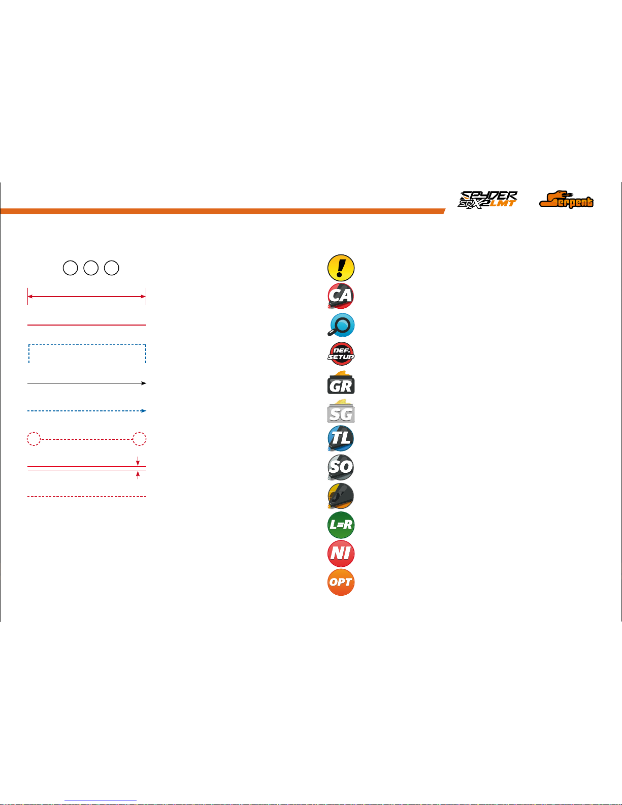
hOW TO USE ThE maNUal
Each step contains a variety of numbers, lines, and symbols. The numbers represent the order in
which the parts should be assembled. The lines are described below.
Each step contains a variety of symbols described below.
ICONS DESCRIpTIONlINES DESCRIpTION
Assembly path of one item into another Detail view to explain assembly or order of parts better.
Group of items (within lines) should be
assembled first
Default set-up: This symbol indicates the default setup.
Glue one item to another Silicone grease: apply a small amount of grease to the parts shown.
Direction the item should be moved
Grease: apply a small amount of grease to the parts shown.
Left and right parts should be assembled in the same way.
Connect one item to another
Thread lock: apply a small amount on the parts shown. Before to apply the threadlock,
make sure to degrease the parts very well, as otherwise the threadlock will not work.
Gap between two items Silicone oil: use the indicated silicone oil for the shocks and differentials.
Parts or items not included in the kit.
Optional part, not standard in the kit.
Carefull, read and check very well.
Step number; the order in which you should
assemble the indicated parts
1 32
Apply a small amount of cyano glue. Use wear protection for eyes and hands.Length after assembly
Press/Insert one item into another Oil: apply a small amount of oil to the parts shown.
O
OIL
bag 1
4
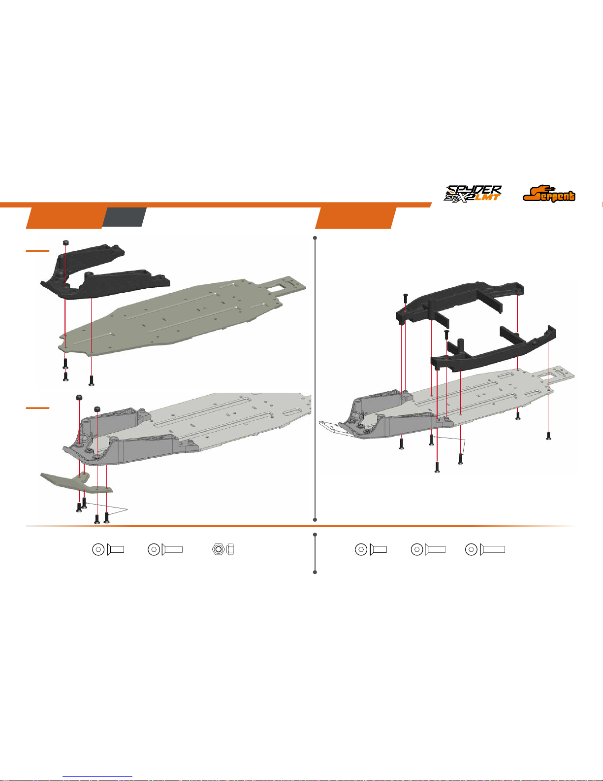
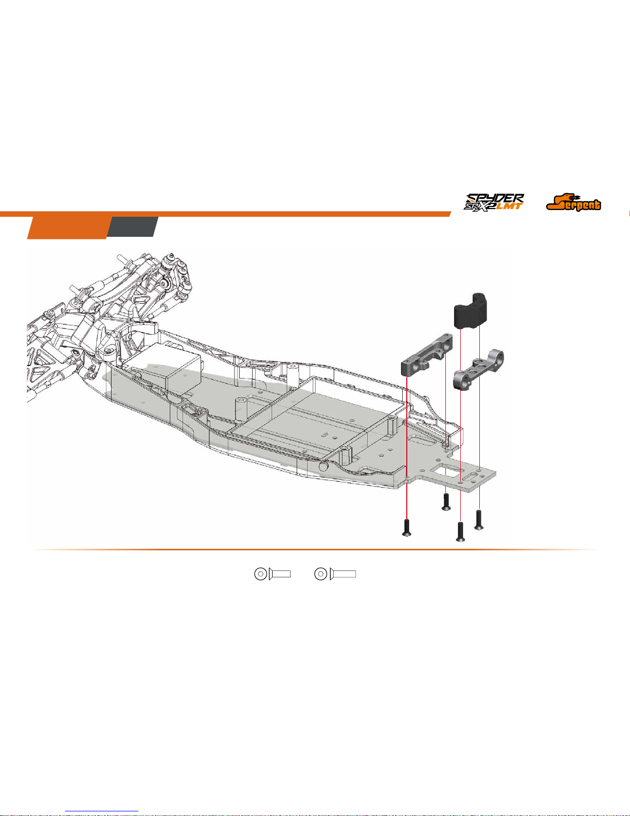
ChaSSIS aSSEmbly
STEp 1
1.1
1.2
STEp 2
M3x8
M3x8
M3x10
M3x10
M3x10
M3x8
M3x12
M3x10
M3x10
M3x10
Nylock nut M3
Nylock nut M3
Nylock Nut M3
M3x10M3x8 M3x10M3x8 M3x12
5
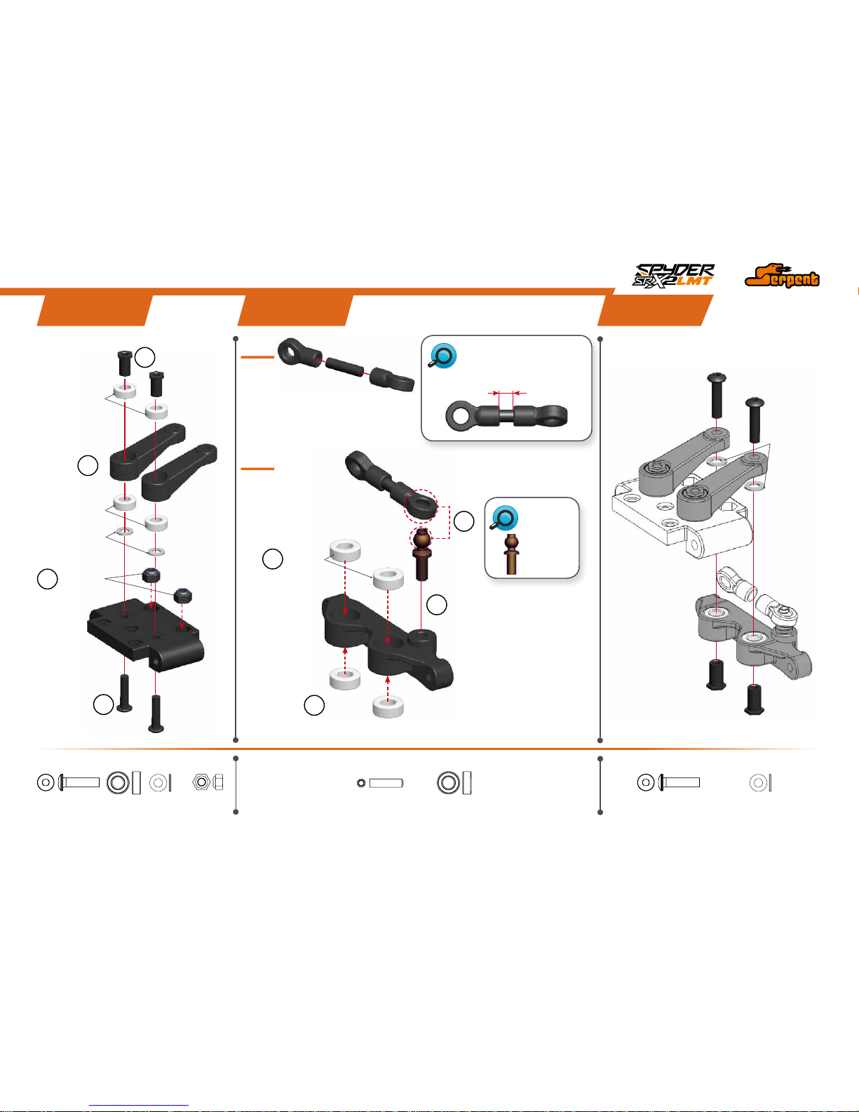
STEERINg aSSEmbly
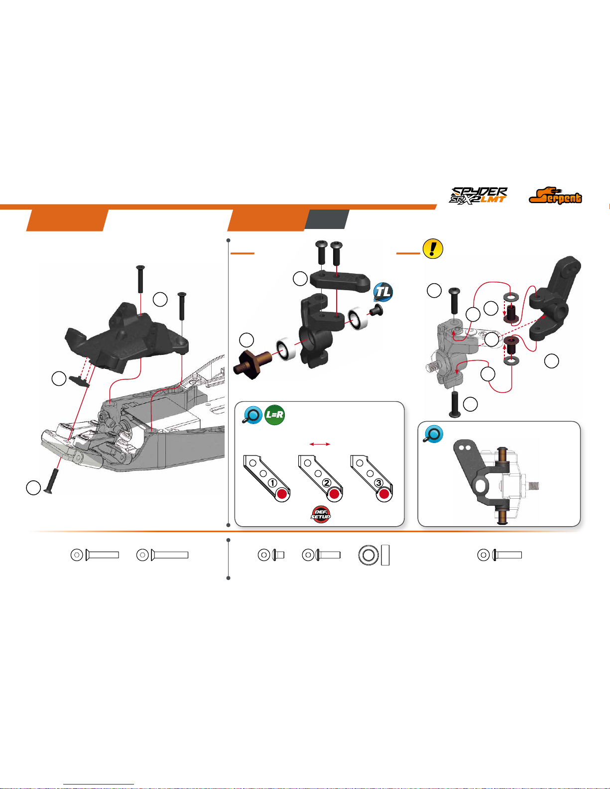
STEp 4
STEp 3
STEp 5
M3x12
M3x12
4x8x3
4x8x3
4x8x3
3x6x0.5
3x6x0.5
4x8x3
1
2
2
2
3
2
1
1
STEERINGLINKLENGTH
The length may differ slightly
per servo-brand.
4.1
4.2
Nylock
nut M3
M3x12
4.7 - 5.2 mm
3x6x0.5
M3x12
Nylock Nut M3
4X8X3 4X8X3
M3x12
3x6x0.5
M3x12
BALLSTUD
LENGTH
HIGH
HIGH
1- Check how many
teeth your servo
spline has (23, 24
or 25) and use the right
lever.
2- Make sure to put the servo
in neutral before mounting
the lever.
6
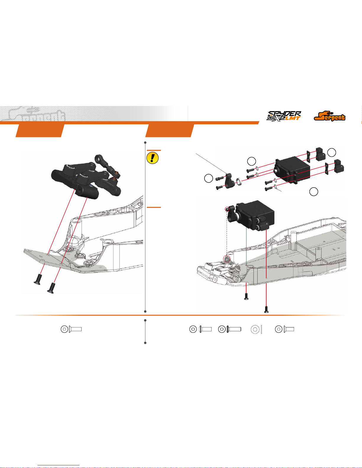
STEp 6 STEp 7
M3x10
M3x10
M3x8
M3x8
3.2x7x0.5
M3x10
7.1
7.2
1
1
1
2
M3x10 M3x8 M3x10
3.2x7x0.5
M3x8
bag 2
7
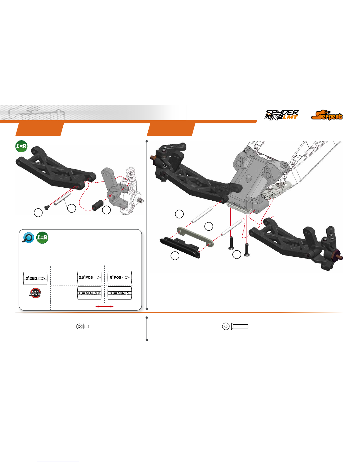
fRONT aSSEmbly
STEp 9STEp 8
M3x16
M3x18
M3x18
M3x12
0.75
0.75
M3x12
1
1
1
4
4
2
2
2
3
STEERINGARMSCHART
LESS
ACKERMANN
MORE
ACKERMANN
STEERINGBLOCKASSEMBLY
9.1
M3x10
M3x4
5x10x4
5x10x4
1
2
M3x18
M3x16 M3x10
5x10x4
M3x12
M3x4
9.2
Place the caster shims and the bushings
in the steering block first. Then slide the
assembly onto the casterblock.
3
8
STEp 10 STEp 11
CASTERBLOCKINSERTS CHART
M2.3x4
3x24
3x33
3x33
1
2
3
1
1
2
3
M3x14
M2.3x4
M3x14
2.5º 5º
Front default caster angle is 25º using the 0º default insert. You can add or
remove caster using the different inserts included in the kit. It is possible to
adjust the caster angle from 20º to 30º in 2.5º steps according the the chart
shown below:
FRONT REAR
+ Caster
- Caster
9
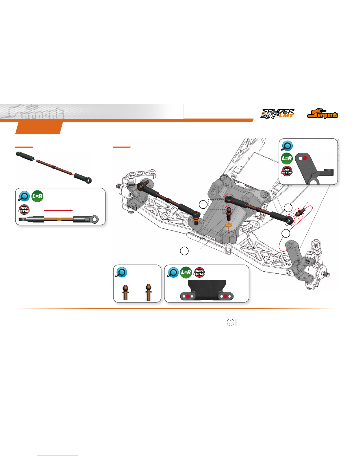
STEp 12
27.3 mm
FRONTCAMBERLINKLENGTH
SHORT
3X6X1
LONG
1
4
12.1 12.2
2
3
CAMBERLINKOUTER
DEFAULTPOSITION
CAMBERLINK INNER
DEFAULTPOSITION
3x6x1
BALLSTUD
LENGTH
SHORT
LONG
10
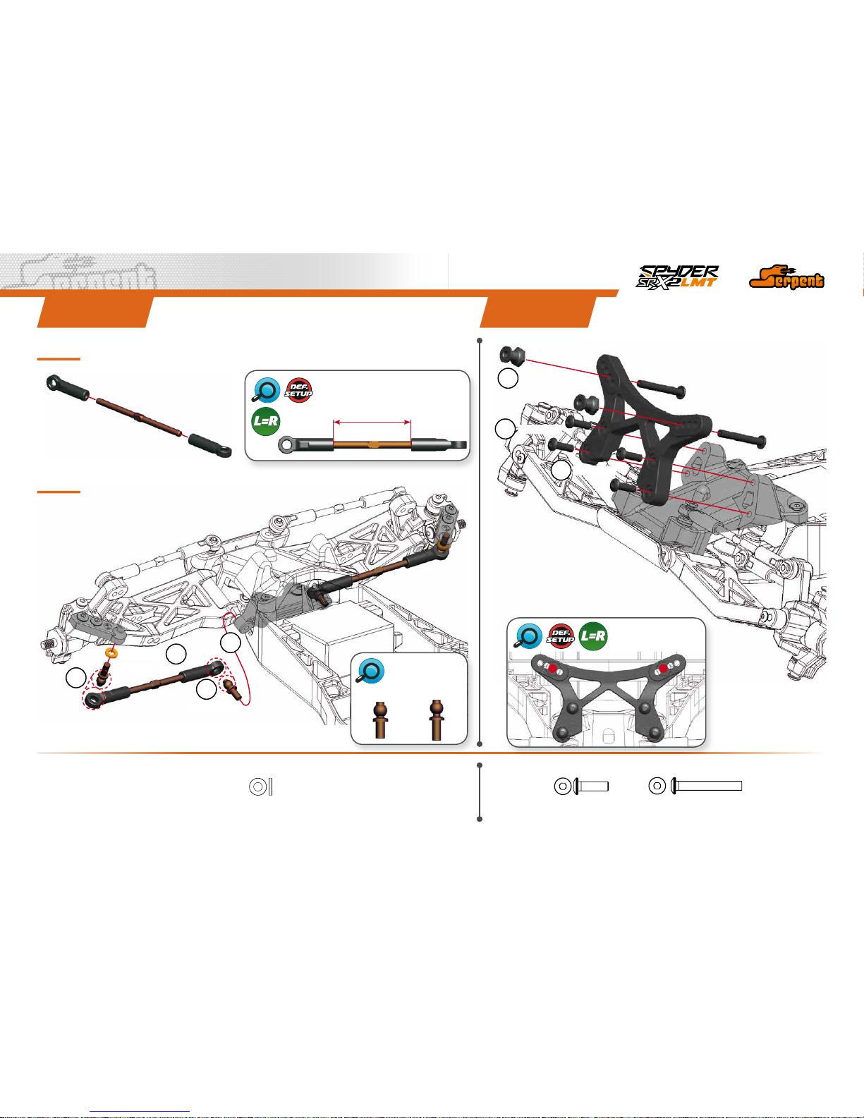
STEp 13 STEp 14
13.1
13.2
31.4 mm
STEERINGTRACKRODLENGTH
FRONTSHOCKS
DEFAULTPOSITION
M3x10
3x6x1
SHORT
LONG
M3x10
M3x22
M3x22
1
1
2
2
2
3
4
3x6x1
M3x10
BALLSTUD
LENGTH
SHORT
LONG
M3x22
bag 3
11
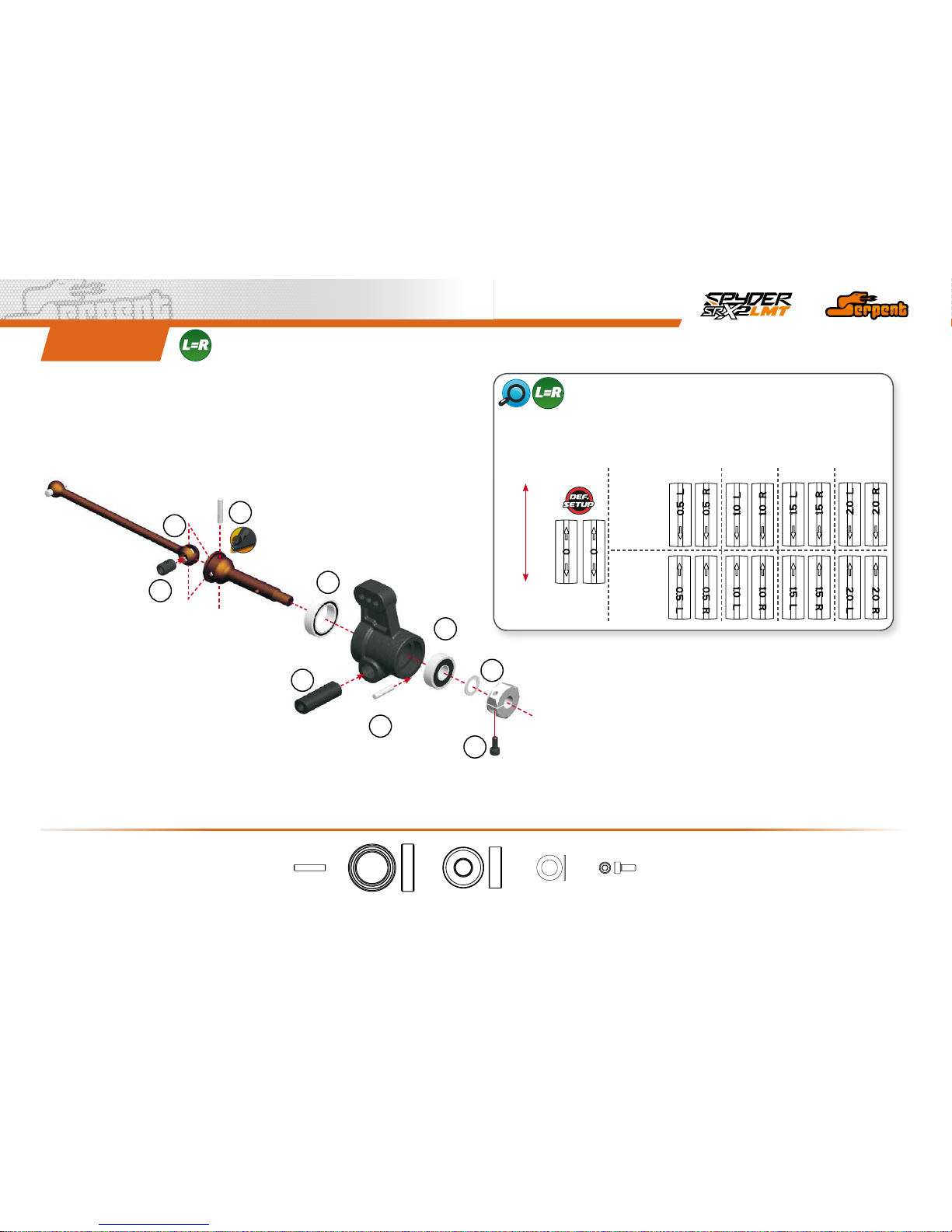
REaR aSSEmbly
STEp 15
M3x10
M3x10
M3x12
M3x12M3x10
12
2x10
10x15x4
5x13x4
5x8x0.3
2
3
4
5
6
7
8
9
1
2x10
M2x5
REARUPRIGHTTOEININSERTS
+ Toe in
0.5º 1º 1.5º 2º
- Toe in
Rear toe-in is established by the rear suspension inserts assembled in step 18. Rear upright
inserts are used to ne tune easily the rear toe in. For instance, if the suspension inserts give -4º
toe in and then is assembled the +1.5º the resulting toe in is -2.5º. Upright inserts are marked with
a R for the right side and L for the left side.
FRONT
REAR
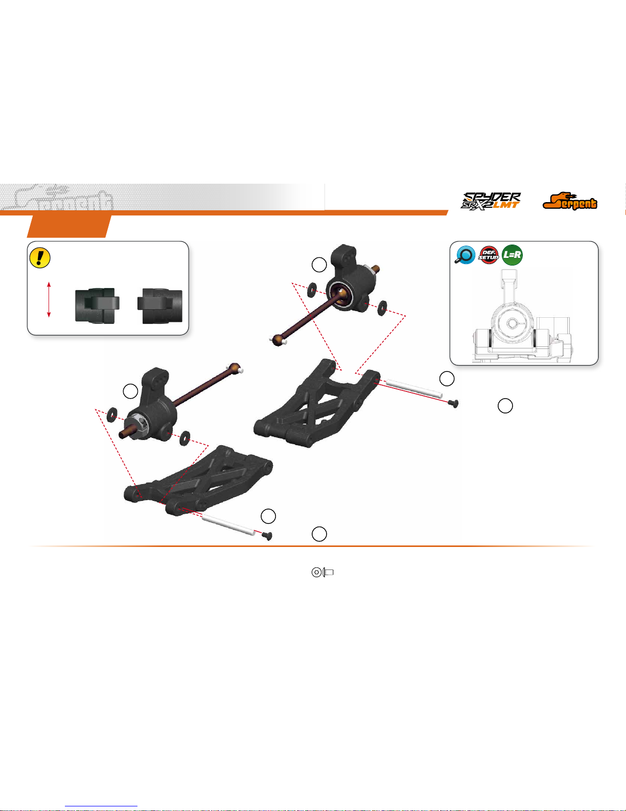
STEp 16
5x8x0.3
2x10
10x15x4
5x13x4
M2x5
O
OIL
13
M2.3x4
M2.3x4
3x33
3x33
3
3
1
1
2
REARDEFAULT
WHEELBASESHIMS
STEp 17
LEFT RIGHT
Notice that rear uprights are not symmetrical.
Check below the correct position of each.
REAR
FRONT
2
M2.3x4
14
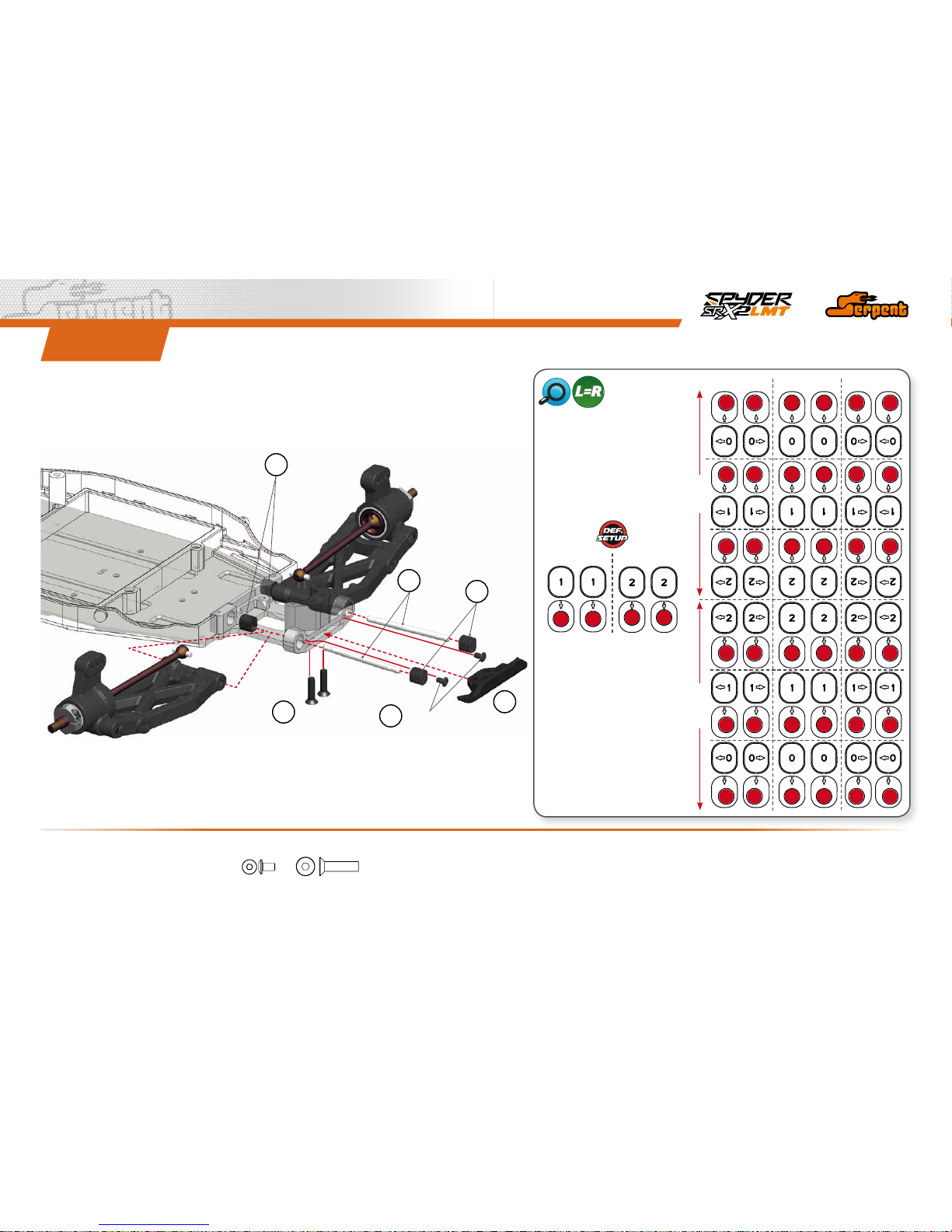
STEp 18
SUSPENSION
INSERTS
MIDNARROW
UP
DOWN
WIDE
M2.3x4
M3x12
2
3
4
5
6
1
M2.3x4
M3x12
FRONT
REAR
The Serpent SRX2 MH is supplied
with a set of inserts with which you
can change the rear roll center and
the rear track width. As you can see
in the right chart you can move in
and out and up and down the rear
pivot pins adjusting also the rear
anti-dive.
 Loading...