

Page 1
INSTRUCTION MANUAL
1/8TH SCALE 4WD COMPETITION CAR
Page 2

- 2 -
- 3 -
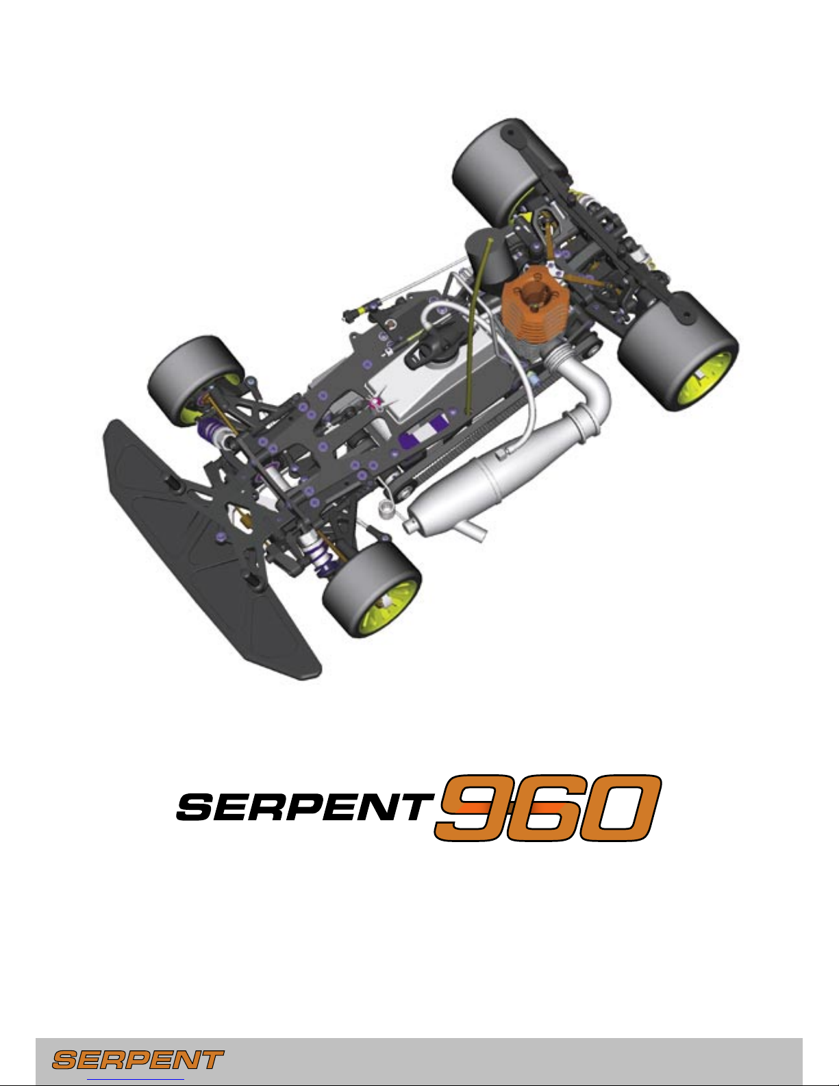
The Serpent 960 is the next evolution of Serpent’s
hugely-successful 950 lineage, combining ultimate
performance into a single package. The Serpent 960
was designed to be a world champion, while still being
easy to use, assemble, and set up. You are now part of
the worldwide network of Serpent drivers, which gives
you superior technical support and access to many
benefits that only Serpent drivers can enjoy.
The Serpent 960 offers many of the same specifications
and features that made the Serpent 950/950R into
top-competition racecars. Continuously pushing the
performance envelope, Serpent’s engineers have added
many new and innovative features that can help take
your Serpent 960 into the winner’s circle: stronger
reinforced components, easier roll-centre adjustment,
redesigned braking system, improved rear suspension
design, adjustable rear anti-roll bar, optional throttle
servo positioning (laydown or upright), new improved
shock absorbers, and new receiver pack configuration.
INSTRUCTIONS
Serpent’s long tradition of excellence extends to their
instruction manuals, and this instruction manual is no
exception. The easy-to-follow layout is richly illustrated
with 3D-rendered full-color images to make your
building experience quick and easy. Following the
instructions will result in a well-built, high-performance
racecar that will soon be able to unleash its full potential
at the racetrack.
This instruction manual has been divided into sections
that will logically lead you through the assembly process
of your Serpent 960. Follow the assembly steps in the
order presented to ensure that no problems occur
during assembly. Each step indicates all the fasteners
and small parts used. Bag numbers identify the kit
bag(s) that contains the appropriate parts.
SETUP
In certain assembly steps you need to make basic
adjustments, which will give you a good initial setup
for your Serpent 960. Fine-tuning the initial setup is an
essential part of building a high-performance racecar
like your Serpent 960. The separate Serpent 960 Setup
Book is an excellent resource for making adjustments
on your Serpent 960 and understanding the concepts
behind those adjustments.
EXPLODED VIEWS AND PARTS LIST
The exploded views and parts lists for the Serpent 960
are contained in a separate Serpent 960 Reference
Guide. The exploded views show all the parts of a
particular assembly step along with the Serpent part
number. The parts lists indicate the part number and
name of each part for easy reference when ordering.
SAFETY
Included with your Serpent 960 kit is a document
entitled “Read This First” that covers safety precautions
for the assembly and use of this product. We strongly
recommend that you thoroughly read and understand
that document, and follow all the precautions.
1.0 FRONT ASSEMBLY 4
2.0 REAR ASSEMBLY 9
3.0 RADIO PLATE ASSEMBLY 14
4.0 RADIO PLATE MOUNTING 17
5.0 GEARBOX ASSEMBLY 21
6.0 CENTAX ASSEMBLY 23
7.0 FINAL ASSEMBLY 26
INTRODUCTION
CONTENTS
Page 3
- 3 -
Length after assembly
USING THE MANUAL
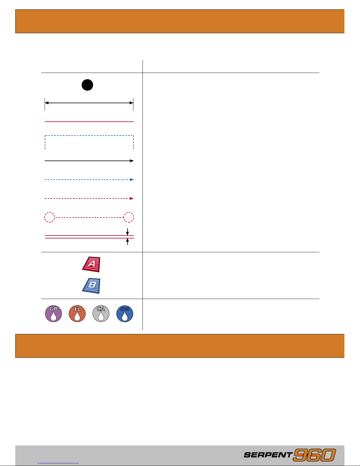
Each step contains a variety of numbers, lines, and symbols. The numbers represent the order in which the
parts should be assembled. The lines and symbols are described below.
LINE / SYMBOL
DESCRIPTION
Assembly path of one item into another
Group of items (within lines) should be assembled first
Direction the item should be moved
Glue one item to another
Press/Insert one item into another
Connect one item to another
Gap between two items
SERPENT.COM
The printed instruction manual included with your
Serpent 960 kit is very complete, though due to
continuous product development, more up-to-date
information is provided at our Serpent.com web portal.
This state-of-the-art R/C technology portal is where
Serpent racers from all over the world meet and
exchange their ideas, and share useful information and
experiences about their Serpent cars.
All information about the Serpent 960 is accessible from
the Serpent 960 product page on Serpent.com. You can
access this page by going to the Products section, and
then search for the ‘Serpent 960’ product name. From
the Serpent 960 product page you will find the very
latest information about your Serpent 960: reports
by team drivers and other experts, tips and tricks,
FAQ, forums, setups, image gallery, downloadable
files, and even streaming video of the Serpent 960 on
how to further improve the car. The latest version of
the instruction manual (including team and racer tips,
and part lists and option lists) will be made available
as downloadable PDF-files and online viewable pages
under ‘i-Manual.’
Apply graphite grease (GR), threadlock (TL), CA glue (CA) or
Serpent’s One-way Lube (OW). (Items not included.)
OW
Step number; the order in which you should assemble the
indicated parts
1
Refer to Serpent 960 Setup Book - Section A: Basic Setup
Refer to Serpent 960 Setup Book - Section B: Advanced Setup
Page 4
- 4 -
- 5 -
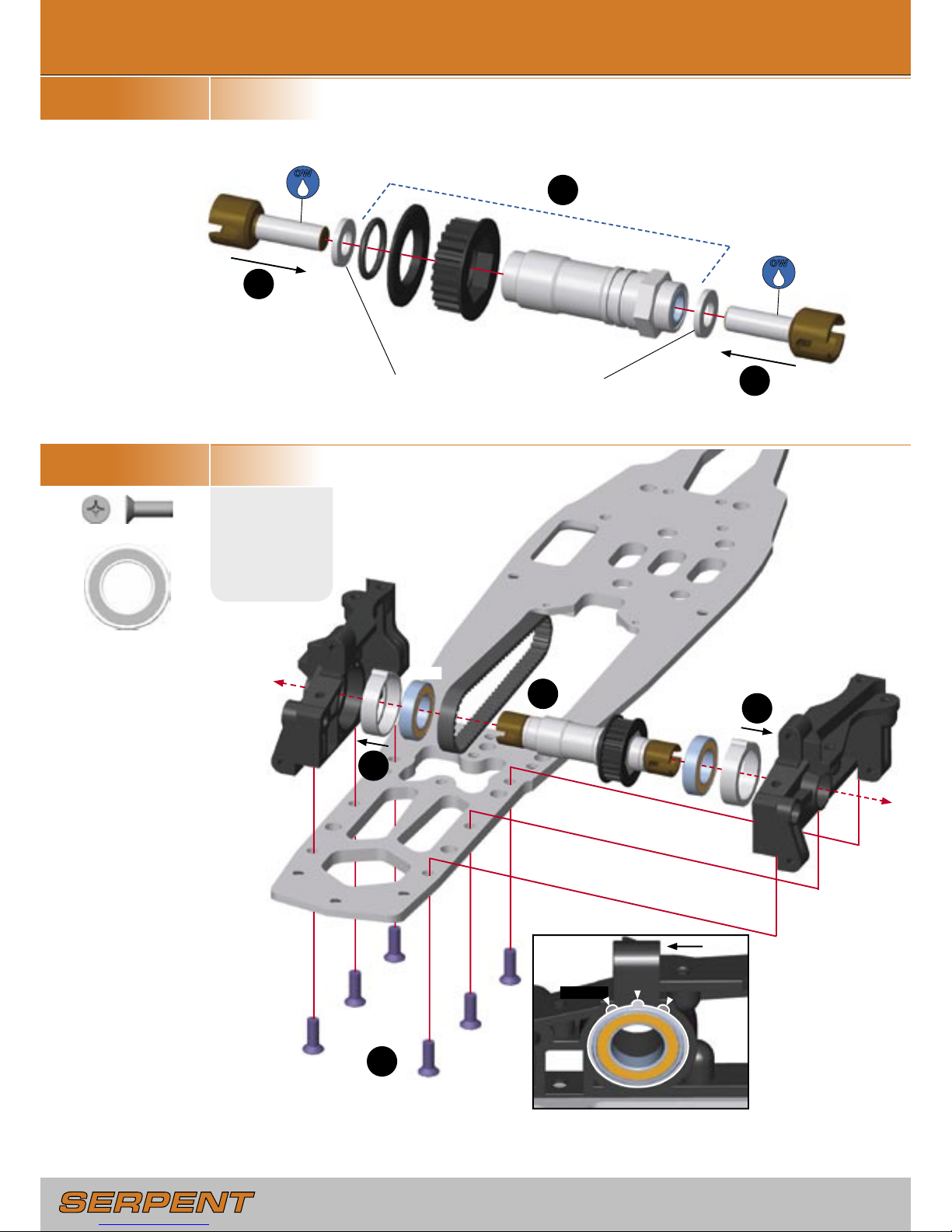
STEP 1.1
BAG 1
STEP 1.2
BAG 2, U1, G12
U14
12x21mm
1.0 FRONT ASSEMBLY
1
2
2
1
2
3
1
Add spacers as required to reduce
endplay of outdrive shafts.
Change the position of
BOTH
eccentric hubs to adjust front belt
tension. Both hubs should have
the same position.
Tighter
Default
Looser
OW
Front
G20
M4x12mm
OW
G20
G20
G20
G20
G20
G20
U14
U14
Page 5
- 5 -
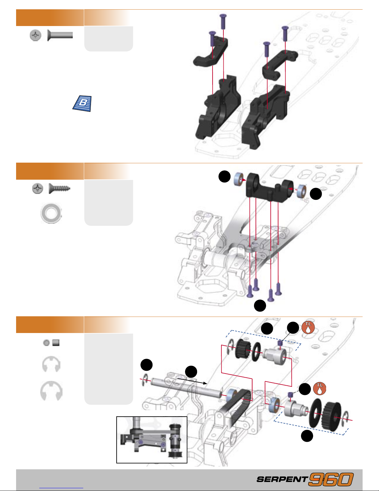
STEP 1.3
G21
M4x16mm
STEP 1.4
BAG U1
B13
3.5x13mm
STEP 1.5
BAG 3
H16
M4x4mm
2
1
2
4
3
5
6
Completed assembly
1
1
U6
6x13mm
R5
5mm
R7
7mm
G21
G21
G21
G21
B13
B13
B13
B13
U6
U6
H16
H16
R7
R7
R5
Learn about front roll
center adjustment
Page 6
- 6 -
- 7 -
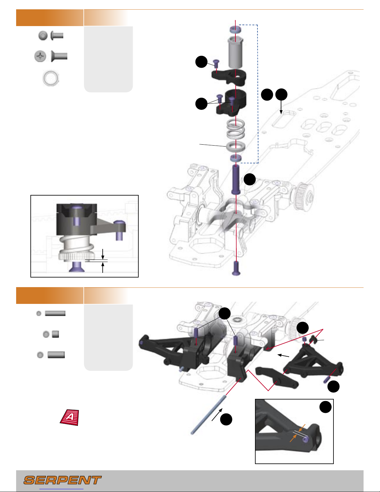
STEP 1.6
BAG 4, U1, G20, E10
E10
M3x6mm
STEP 1.7
BAG 5, 6
H13
M3x12mm
3
1
2
4
2
4
3
1
1
Assemble both front lower arms
using the indicated steps.
5
0.5mm
2mm
Wheelbase
spacer (4mm)
U5
6x10mm
H16
M4x4mm
H19
M4x10mm
U5
G19
G19
M4x10mm
E10
E10
U5
H19
G19
H16
H13
Preload Collar
Set front downstops
and wheelbase
Page 7
- 7 -
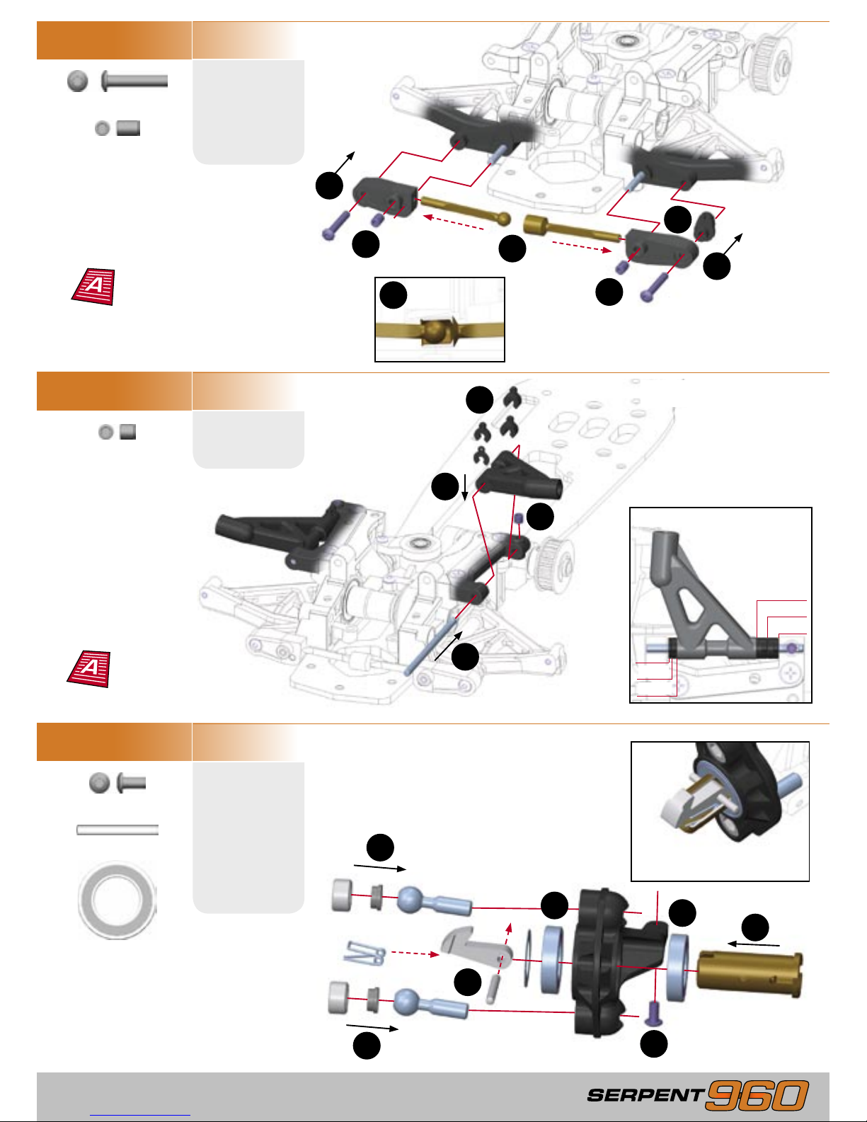
STEP 1.8
E29
M3x18mm
STEP 1.9
BAG 7
H16
M4x4mm
STEP 1.10
BAG 8, U10, E10
E10
M3x6mm
1
4
4
3
3
2
3
2
1
5
2
1
1
4
3
Assemble both front upper arms
using the indicated steps.
Assemble both steering blocks
using the indicated steps.
4mm
4mm
2mm
1mm
Spacer Placement
Press spring into end of front
axle until it snaps into place.
3 x caster spacers
1 x wheelbase spacer
4
2
Press anti-roll bars into mounts far
enough so the bars do not bind when
the suspension is compressed.
1
H17
M4x6mm
P10
2.5x22mm
U14
12x21mm
H17
H17
E29
E29
H16
E10
U14
U14
P10
Set front anti-roll bar
Set Caster and
wheelbase
Page 8
- 8 -
- 9 -
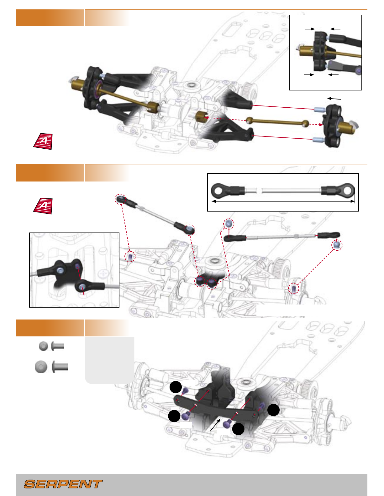
STEP 1.11
BAG 9
STEP 1.12
STEP 1.13
E10
M3x6mm
IMPORTANT! Ensure the front suspension
moves up and down freely without binding.
15mm
18mm
Assemble L & R steering rods:
86.5mm
E18
E18
TOP
BOTTOM
E18
M4x8mm
E10
E10
1
1
2
2
Set front track-width
and camber
Set front toe
Page 9
- 9 -
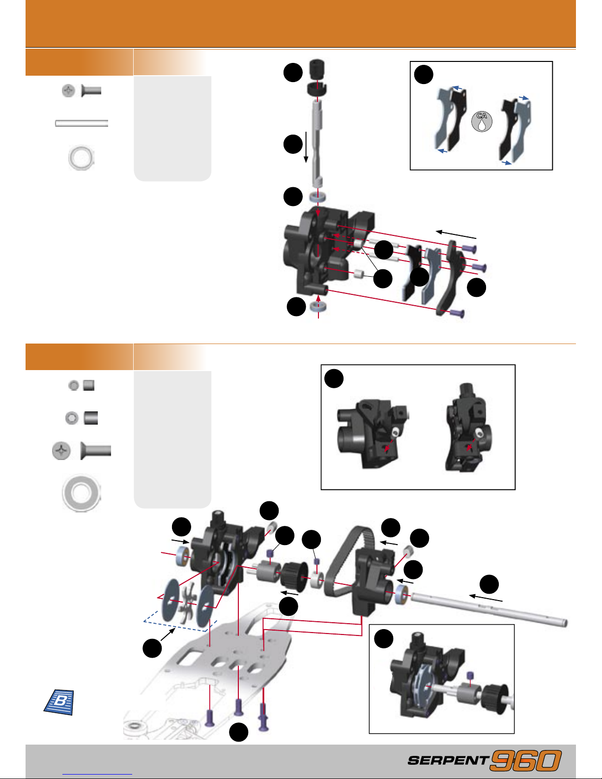
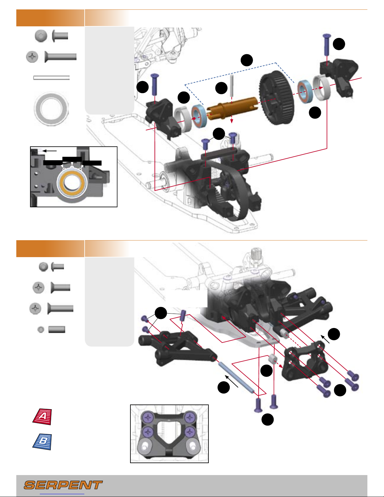
STEP 2.1
BAG 10,11
G11
M3x8mm
STEP 2.2
BAG 12, U1, G20
H16
M4x4mm
2.0 REAR ASSEMBLY
2
3
4
8
6
4
8
3
9
5
7
2
6
7
3
5
2
P9
2.5x20mm
H22
M5x4mm
U8
6x15mm
1
Roughen the metal plates
with sandpaper before gluing
U5
U5
P9
G11
G11
G11
P9
U5
6x10mm
H22
U8
U8
G20
M4x12mm
H16
G20
G20
G20
G20
1
1
1
Left Block
Right Block
H22
5
Note orientation of front
inserts. Ensure BOTH inserts
have the same position.
Learn about rear roll
center adjustment
Page 10
- 10 -
- 11 -
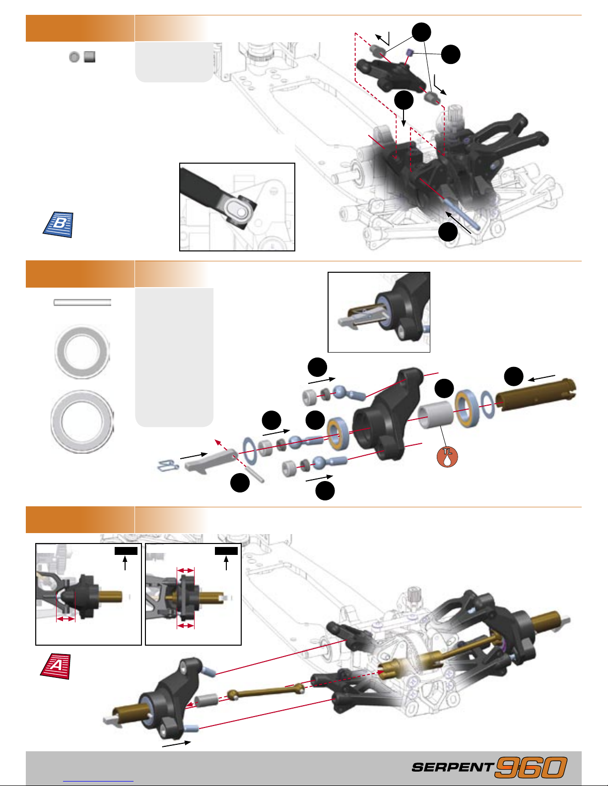
STEP 2.3
BAG 13, U1, G20
E18
M4x8mm
STEP 2.4
BAG 14, E10
E10
M3x6mm
1
2
3
4
5
1
3
6
5
4
Change the position of BOTH
eccentric hubs to adjust rear belt
tension. Both hubs should have the
same position.
Looser
Default
Tighter
Note orientation of rear inserts.
Ensure
BOTH inserts have the
same position, and that they
match the positions of the front
inserts (see step 2.2)
Front
3
4
G22
M4x20mm
P10
2.5x22mm
U14
12x21mm
G20
M4x12mm
H19
M4x10mm
2
Assemble both rear lower arms
using the indicated steps.
Thread set screw
until ush with
bottom of arm.
G22
E18
E18
P10
G22
U14
U14
G20
G21
G20
G21
G20
G20
E10
E10
H19
G21
M4x16mm
Set rear downstops
Learn about rear roll
center adjustment
Page 11
- 11 -
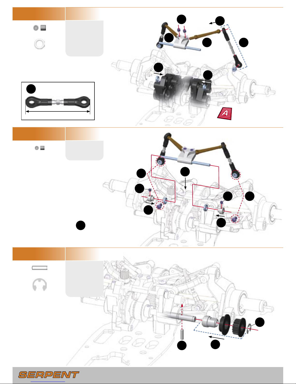
STEP 2.5
H16
M4x4mm
STEP 2.6
BAG 15, 16, U1
P10
2.5x22mm
STEP 2.7
3
4
2
1
1
1
1
4
3
Note orientation of front and
rear inserts. Ensure BOTH
inserts have same position.
Press spring into end
of rear axle until it
snaps into place.
Assemble both rear upper arms
using the indicated steps.
Assemble both rear hubs
using the indicated steps.
U14
12x21mm
U15
15x24mm
2
2
Insert foam into wheel axle to
reduce driveshaft play.
H16
U15
U14
P10
20mm
18mm
16.5mm
Front
Front
TOP BOTTOM
Apply thread lock
to the inside of the
aluminium spacer
Learn about rear
camber rise adjustment
Set rear track-width,
camber and toe
Page 12
- 12 -
- 13 -
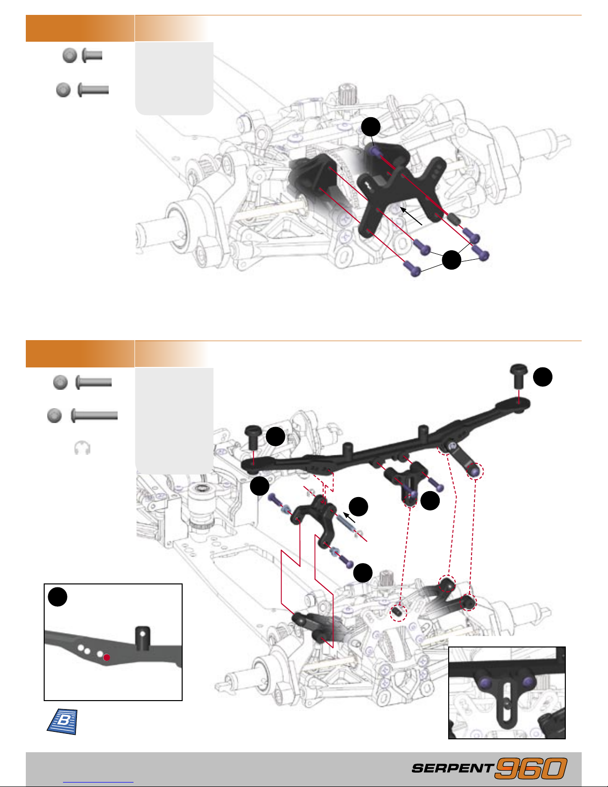
STEP 2.8
BAG 17
H8
M3x3mm
STEP 2.9
STEP 2.10
P12
3x12mm
2
1
3
1
3
3
2
2
4
Slide pivot shafts through ballbearings one at a time. Center
the anti-roll bar assembly before
securing in place with collars.
1
1
2
2
3
4
5
5
Assemble L & R linkages
50mm
R5
5mm
1
H16
M4x4mm
U3
5x8mm
U3
U3
H16
H8
H8
P12
R5
4
Set rear anti-roll bar
Page 13
- 13 -
STEP 2.11
BAG 18, E10
E10
M3x6mm
STEP 2.12
BAG 19
E14
M3x16mm
2
1
1
3
4
4
Completed assembly
E12
M3x10mm
R2
2mm
2
2
E13
M3x12mm
E12
E12
E12
E12
E10
E13
E13
E14
E14
R2
R2
Default Rear Body Mount
Mounting Position
3
Learn about rear
bodymount adjustment
Page 14
- 14 -
- 15 -
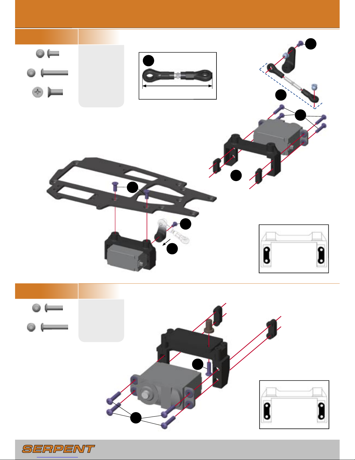
STEP 3.1
BAG 20, G19
E10
M3x6mm
STEP 3.2
BAG 21
E12
M3x10mm
3.0 RADIO PLATE ASSEMBLY
Note the orientation of the
servo mounting screw blocks.
Reverse the default orientation
to mount a smaller servo.
OPTION 1:
Laydown Throttle Servo
Use the following servo arms
with these brands of servos.
23 - Sanwa / KO / JR
24 - Hitec
25 - Futaba
THROTTLE SERVO
Servo output shaft must be
towards REAR of the car.
2
1
E14
M3x16mm
G19
M4x10mm
E14
M3x16mm
STEERING SERVO
Servo output shaft must be
towards FRONT of the car.
Steering Linkage
45.5mm
2
4
5
6
1
1
2
3
Note the orientation of the
servo mounting screw blocks.
Reverse the default orientation
to mount a smaller servo.
G19
E10
E14
E14
E14
E14
G19
E10
E12
E14
E14
E14
E14
Page 15
- 15 -
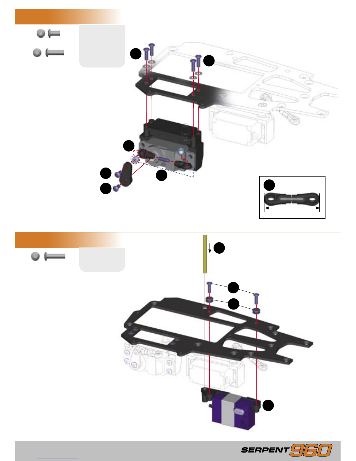
STEP 3.3
BAG 22
E10
M3x6mm
STEP 3.4
Securely attach receiver to mounting plate.
Use the following servo arms
with these brands of servos.
23 - Sanwa / KO / JR
24 - Hitec
25 - Futaba
Throttle Linkage
36mm
OPTION 1: Laydown Throttle Servo
1
5
5
1
4
3
2
1
2
3
4
RACING TIP:
To protect the receiver against
fuel and moisture, seal the wired receiver
into a rubber balloon before mounting it.
E12
M3x10mm
E13
M3x12mm
OPTION 1:
Laydown Throttle Servo
E10
E10
E12
E12
E13
E13
Page 16
- 16 -
- 17 -
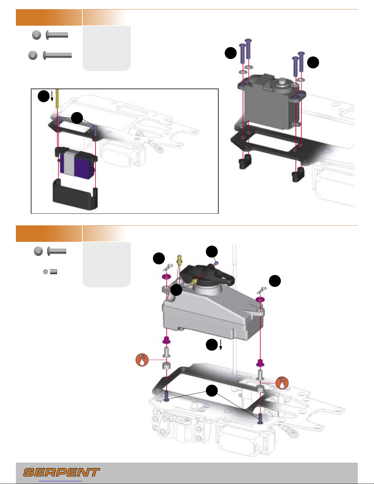
STEP 3.5
E13
M3x12mm
STEP 3.6
BAG 23
E12
M3x10mm
Securely attach receiver to mounting plate.
1
1
2
3
OPTION 2: Upright Throttle Servo
RACING TIP: To protect the receiver against
fuel and moisture, seal the wired receiver
into a rubber balloon before mounting it.
1
5
5
4
3
2
E14
M3x16mm
H9
3x4mm
FUEL CAP FITTING PLACEMENT
CW tracks: Fitting on RIGHT side.
CCW tracks: Fitting on LEFT side.
E14
E14
E13
E13
E12
E12
H9
Page 17
- 17 -
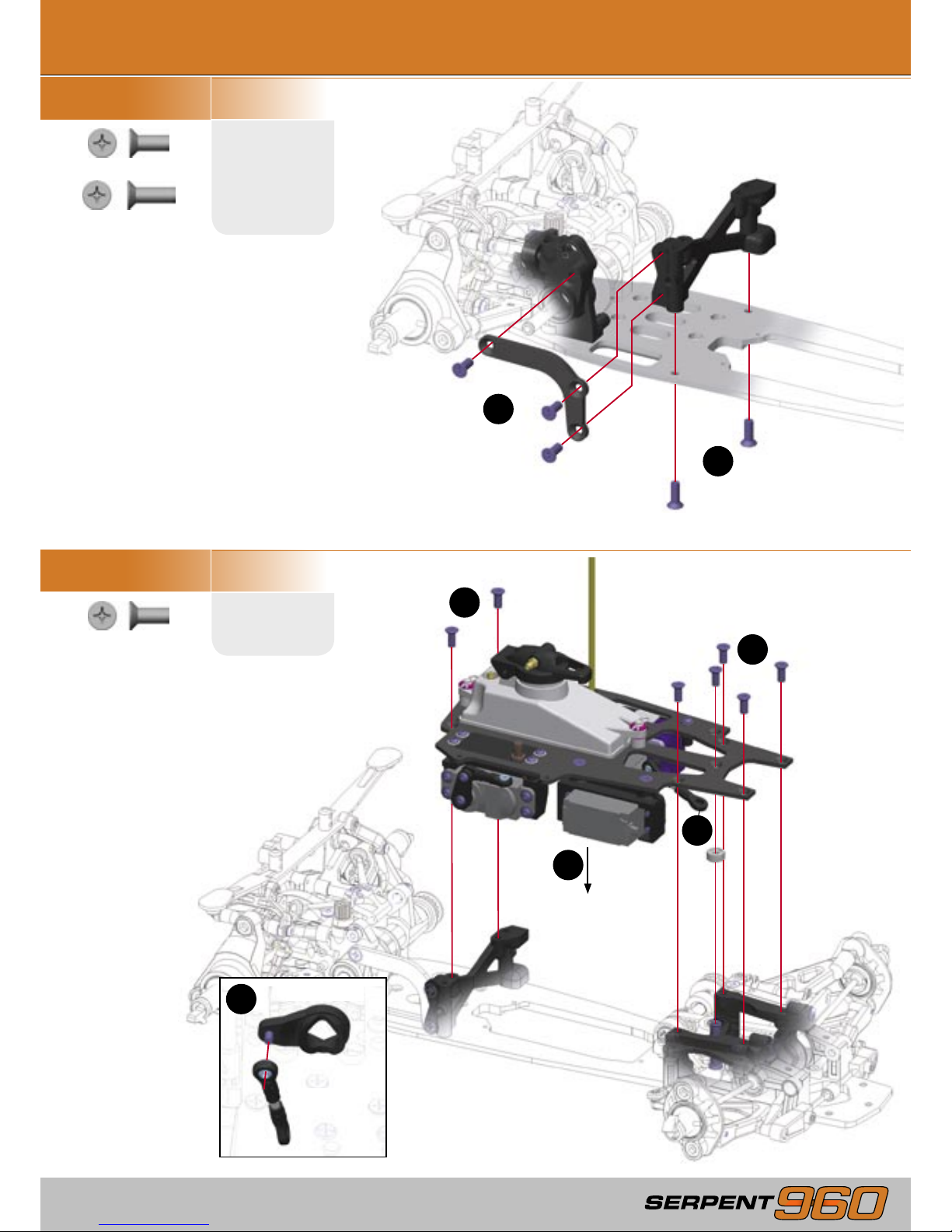
STEP 4.2
STEP 4.1
BAG 24, G19, G20
G19
M4x10mm
BAG G19
G19
M4x10mm
4.0 RADIO PLATE MOUNTING
1
2
1
2
2
3
Servo Saver
Steering
Linkage
3
G20
M4x12mm
G19
G19
G19
G20
G20
G19
G19
G19
G19
G19
G19
G19
Page 18
- 18 -
- 19 -
STEP 4.3
H16
M4x4mm
1
2
2
STEP 4.4
BAG D
1
2
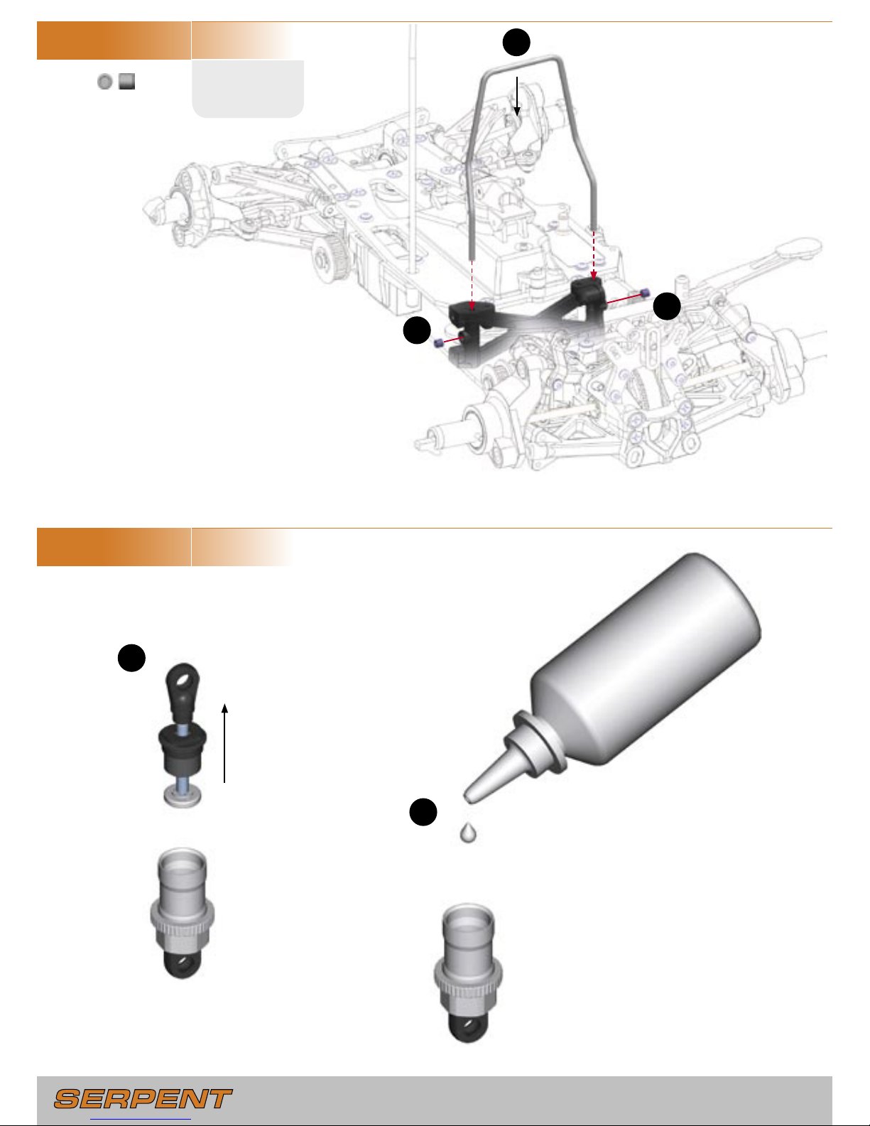
Unscrew the bottom half of
the pre-assembled shock
absorbers.
FILLING
Fill the shock body with the supplied
shock absorber oil.
BLEEDING
Let the oil settle and allow the air to
escape. Slowly move the piston up
and down to release any trapped air
bubbles. Repeat as necessary until no
bubbles appear.
H16
H16
Page 19
- 19 -
STEP 4.6
BAG 25, E10
E10
M3x6mm
1
3
4
4
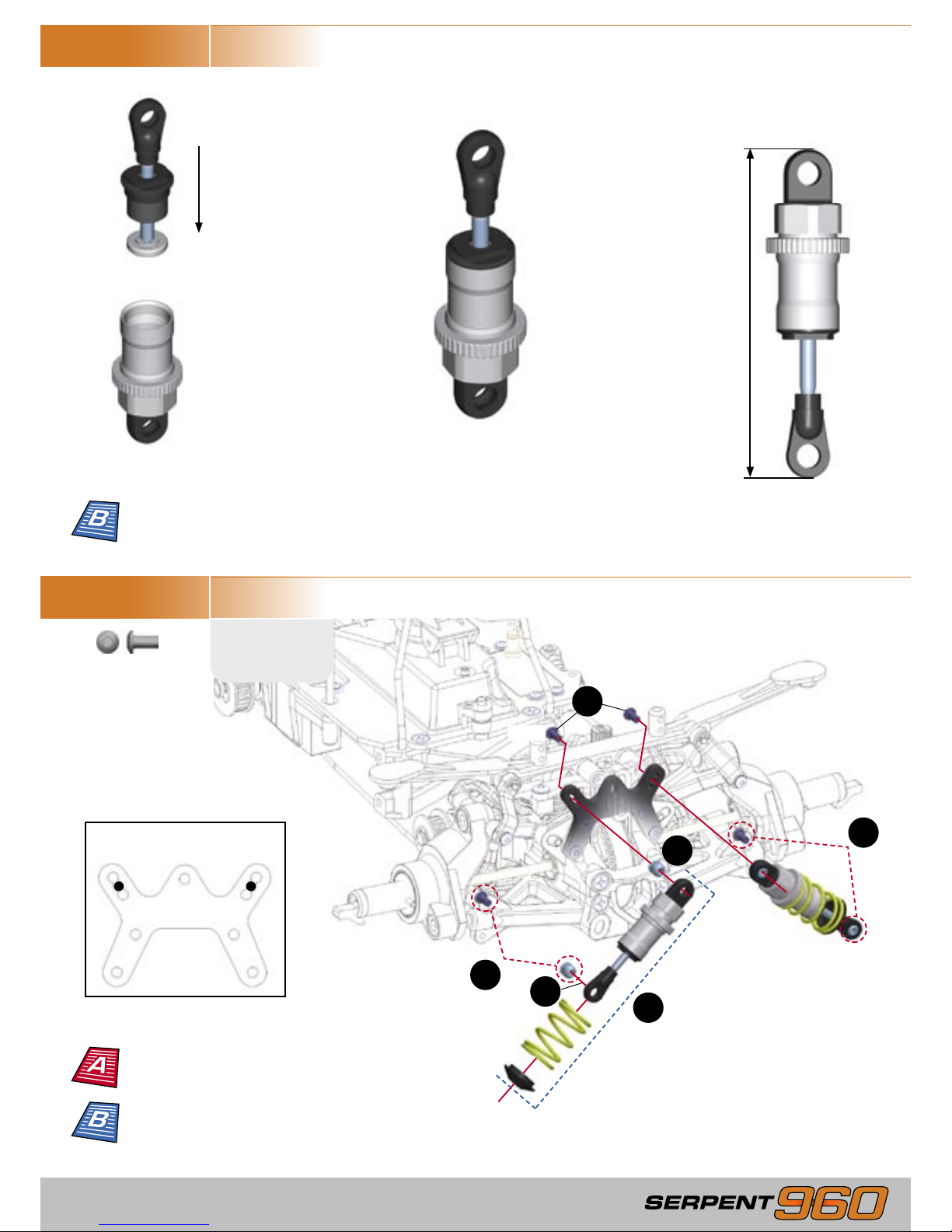
Note the upper shock mount
holes used.
STEP 4.5
With the shock body lled with
oil, slowly screw the bottom half
of the pre-assembled shock back
onto the shock body.
IMPORTANT! Do not cross
thread!
Oil will overow through the
built-in bleed channel in the
threads.
Front shock
68mm
Rear shock
73mm
2
2
E10
E10
Learn about shock
damping
Learn about shock
adjustment (damping,
springs, preload)
Set rear shock position
Page 20
- 20 -
- 21 -
STEP 4.7
BAG E10
STEP 4.8
BAG G19
A13
M3x13mm
STEP 4.9
G19
M4x10mm
1
3
4
4
3
1
2
1
2
3
3
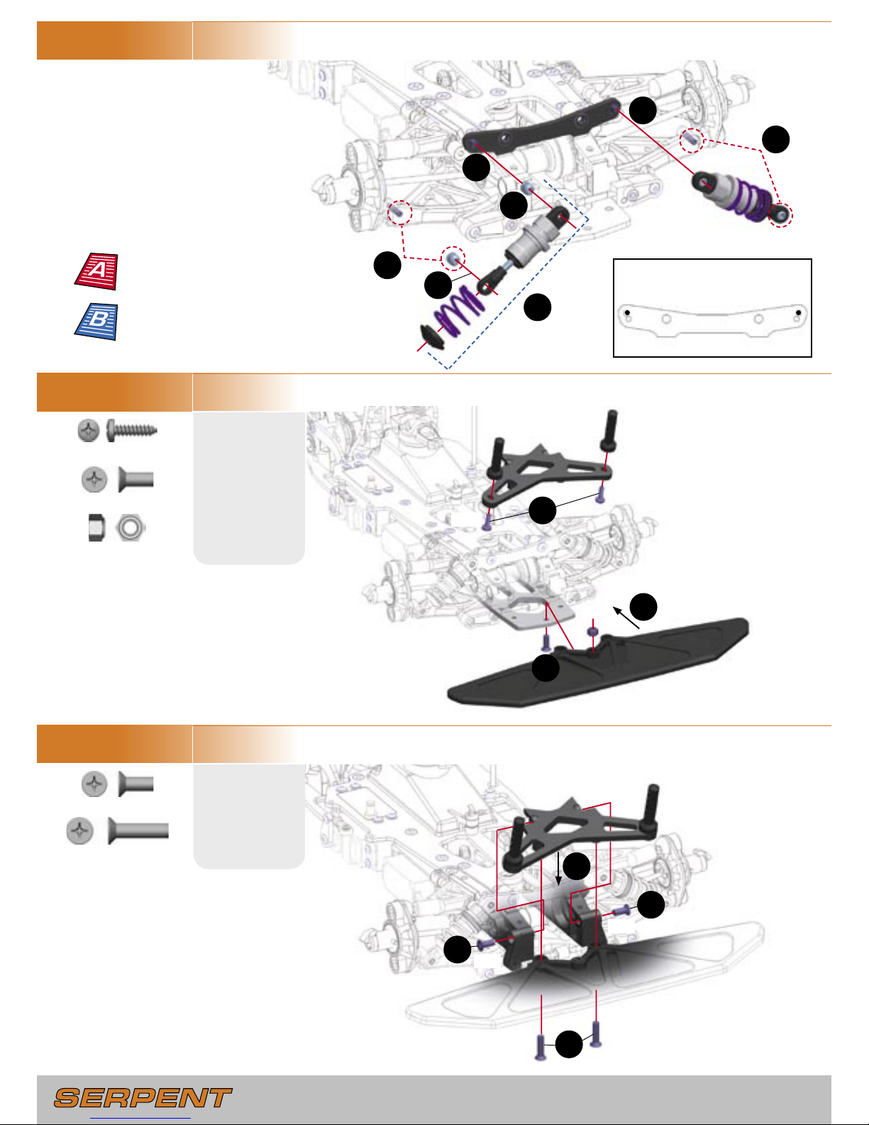
Note the upper shock mount
holes used.
2
2
G19
M4x10mm
L4
M4
G21
M4x16mm
A13
A13
G19
L4
G21
G21
G19
G19
3
Learn about shock
adjustment (damping,
springs, preload)
Set front shock position
Page 21
- 21 -
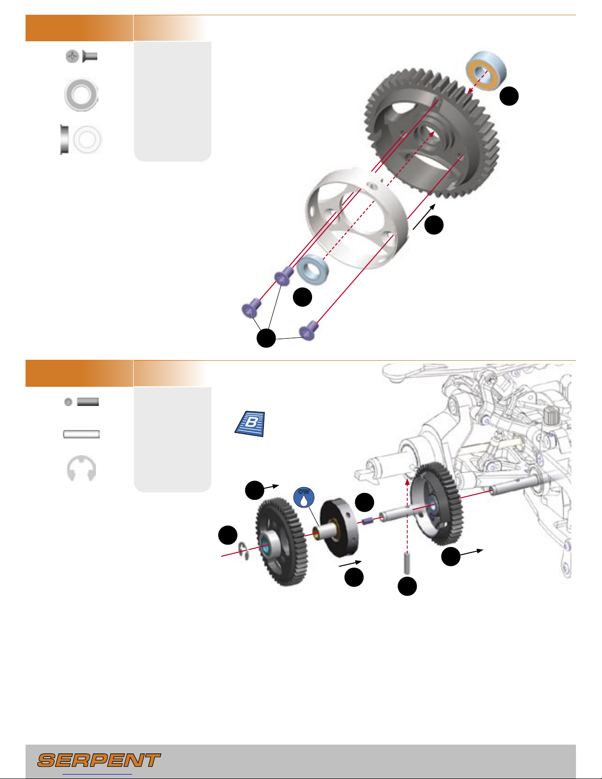
STEP 5.1
BAG 26
E13
M3x12mm
STEP 5.2
BAG 27
G10
M3x6mm
5.0 GEARBOX ASSEMBLY
3
3
4
4
1
1
2
2
1
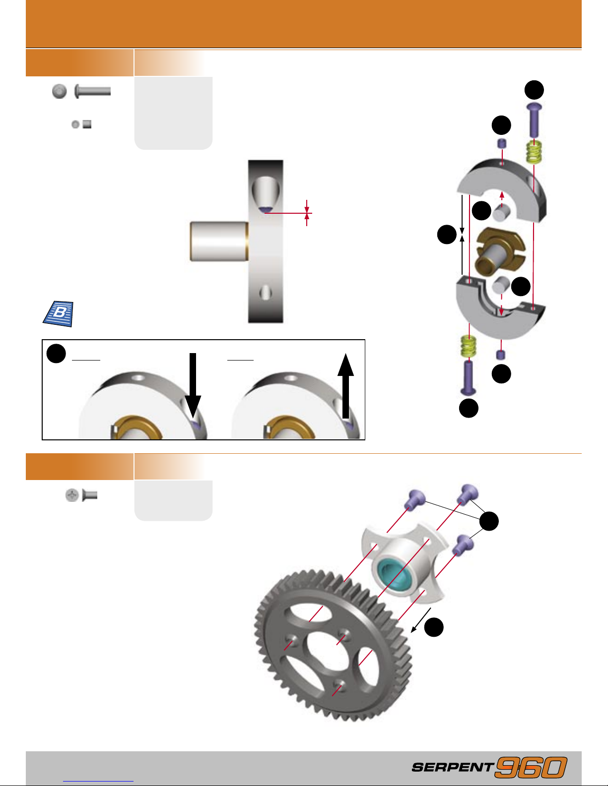
Start with screw head
ush with bottom edge of
hole. Both screws must be
set equally.
TO SHIFT LATER
Tighten both screws equally
3
TO SHIFT EARLIER
Loosen both screws equally
SHIFT POINT
screw
GAP SETTING
screw
GAP SETTING
screw
1st Gear
48 T
H8
M3x3mm
SHIFT POINT
screw
H8
H8
E13
E13
G10
G10
G10
Learn about shift point
and shoe gap
Page 22
- 22 -
- 23 -
STEP 5.3
G10
M3x6mm
STEP 5.4
H11
M3x8mm
1
3
4
2
6
2
1
4
5
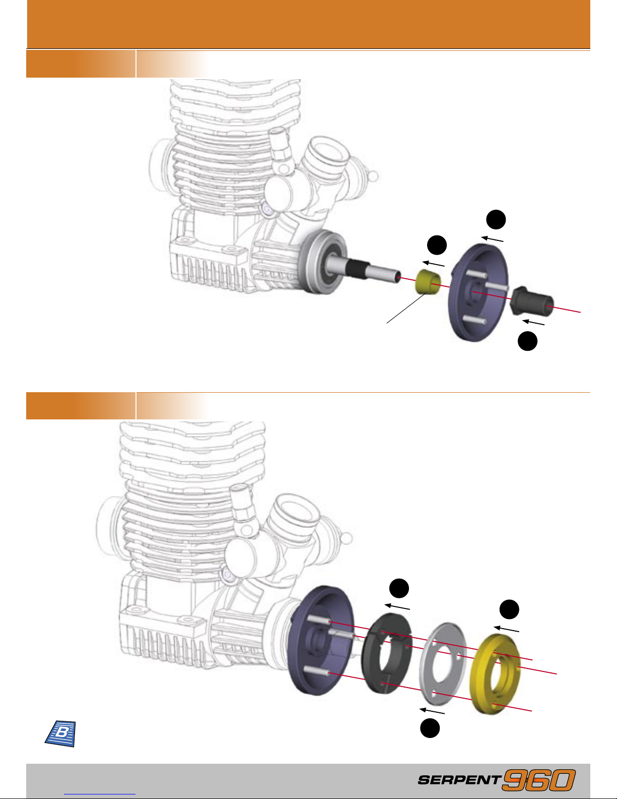
ADJUSTING THE 2-SPEED SHOE GAP
Loosed the two gap-setting set screws to allow the shoes to rest on the drive
adaptor.
Install the 2-speed shoes in the 2nd gear drum, but do NOT install the 1st gear.
There should be equal but minimal spacing between the 2-speed shoes and the 2nd
gear drum. Tighten BOTH gap setting set screws until the shoes touch the inside
surface of the aluminum 2nd gear drum, then loosen BOTH set screws by 1/2 turn
each. The 2nd gear should spin freely.
Install the rst gear.
OW
2nd Gear
45 T
U6
6x13mm
V5
6x10mm
P13
3x14mm
R5
5mm
3
G10
G10
G10
V5
U6
P13
H11
R5
Learn about shoe gap
Page 23
- 23 -
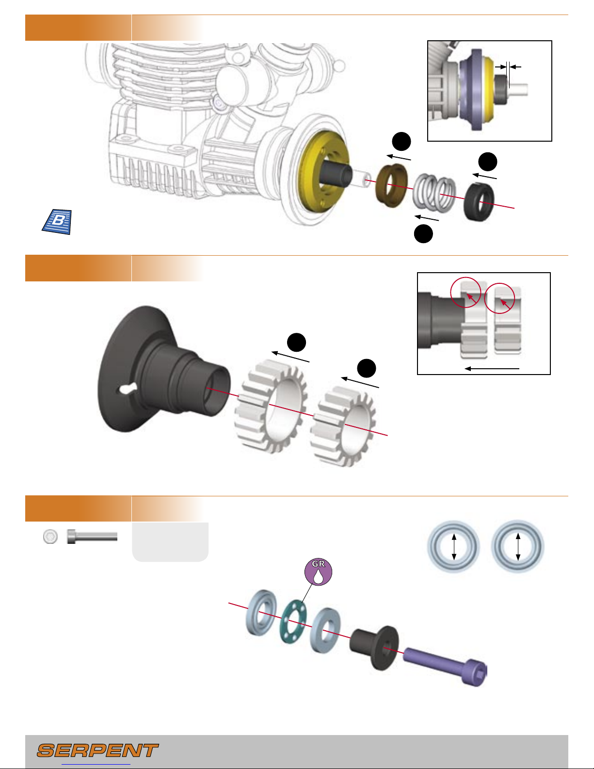
STEP 6.1
BAG 28
STEP 6.2
6.0 CENTAX ASSEMBLY
1
2
3
IMPORTANT! Use the cone that comes with your engine
1
2
3
Learn about clutch
shoes and yweights
Page 24
- 24 -
- 25 -
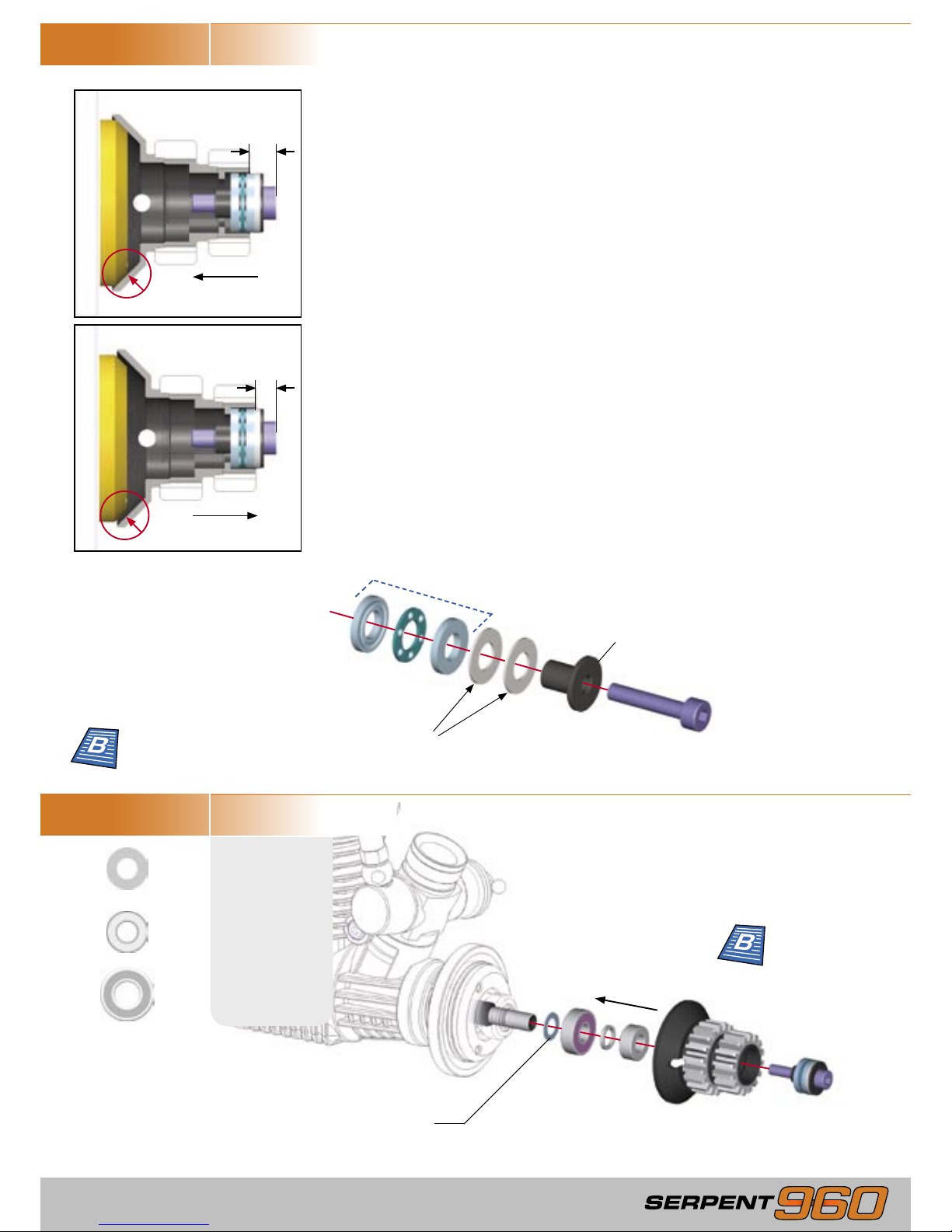
STEP 6.3
BAG 29
STEP 6.4
STEP 6.5
F14
M3x16mm
Large inner dia.
Small inner dia.
1
3
2
1.2mm
1
2
2nd Gear
19 T
1st Gear
16 T
Note inside shoulders
A
B
A B
5.2mm 5.0mm
IMPORTANT! Install thrust bearing
plates as shown
F14
Initial clutch spring tension
Learn about clutch
spring preload
Page 25
- 25 -
STEP 6.6
STEP 6.7
M14
5x10x0.1mm
5x10x0.3mm
Install only the clutchbell and the thrustbearing assembly on the engine crankshaft. Push the
clutchbell onto the clutch shoe, and then measure the distance A as indicated.
Pull the clutchbell away from the clutch shoe, and then measure the distance B as indicated.
The clutch gap is A – B; the correct gap is 0.7mm.
If the clutch gap is greater than 0.7mm, you can easily calculate the thickness of shims
required to set the correct gap:
Thickness of shims required (in mm) = A – B – 0.7
For example, using the values A=1.3mm, B=0.3mm
Shim thickness = 1.3 – 0.3 – 0.7 = 0.3mm
Place shims between the outer thrustbearing plate and the rim of the thrustbearing carrier as
shown.
Thrustbearing
Thrustbearing carrier
Place shims here
Place small shims to remove all
but a small amount of end play
ADJUSTING THE END PLAY
U4
5x10mm
U45
5x13mm
ADJUSTING THE CLUTCH GAP
1
2
3
4
Pull
Push
M14
U45
U4
A
B
Learn about clutch
shoe gap
Learn about clutch
end play
Page 26
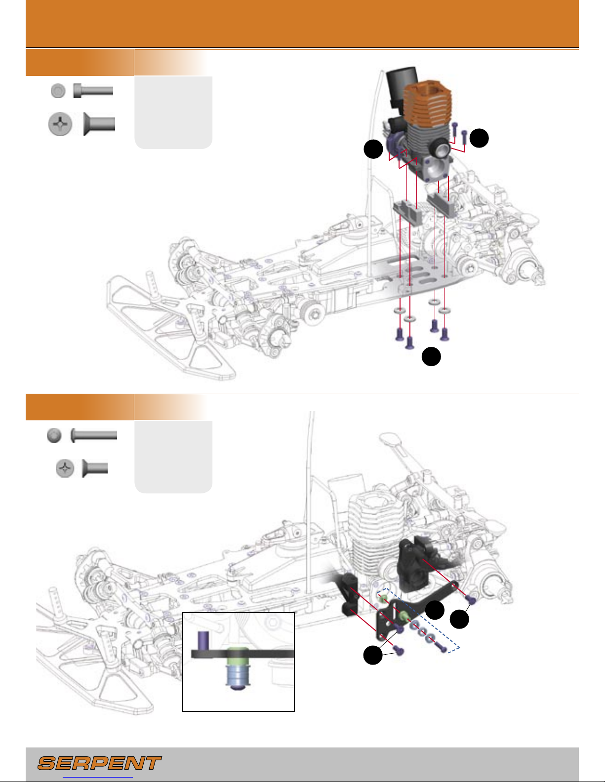
- 26 -
- 27 -
STEP 7.1
BAG 30
F13
M3x12mm
STEP 7.2
BAG 31, G19
E14
M3x16mm
7.0 FINAL ASSEMBLY
1
2
2
1
2
2
Orientation of belt tensioner
bearings
Adjust gear mesh to proper gap
G27
M5x12mm
G19
M4x10mm
F13
F13
G27
G27
E14
G19
G19
Page 27
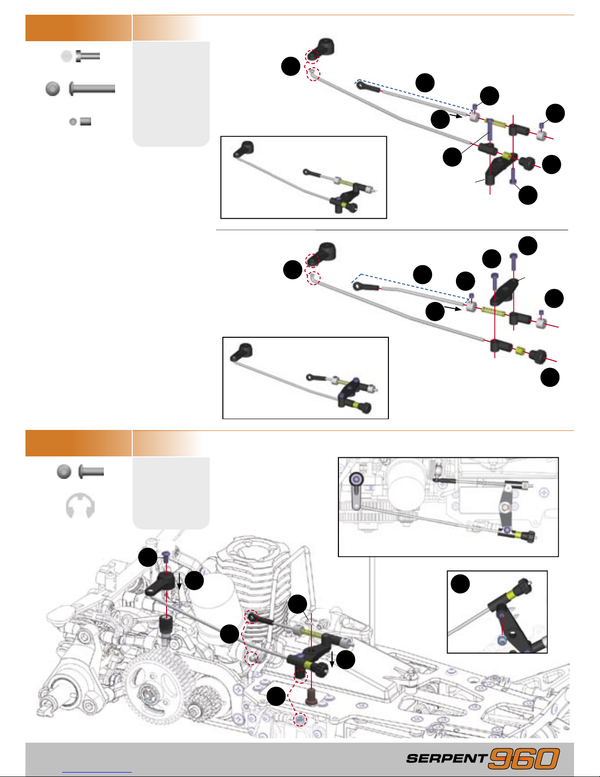
- 27 -
STEP 7.3
BAG 32, 33
C5
2.5x8mm
STEP 7.4
E11
M3x8mm
1
3
4
5
6
7
8
1
6
7
5
3
4
2
8
2
1
2
3
4
5
E14
M3x16mm
H9
M3x4mm
OPTION 2:
Upright Throttle Servo
OPTION 1:
Laydown Throttle Servo
R5
5mm
C5
C5
C5
H9
H9
H9
H9
E14
E11
R5
Use the following servo arms
with these brands of servos.
23 - Sanwa / KO / JR
24 - Hitec
25 - Futaba
6
Completed throttle/brake linkage
5
OPTION 1: Laydown Throttle Servo
Servo Arm
Throttle Lever
Page 28
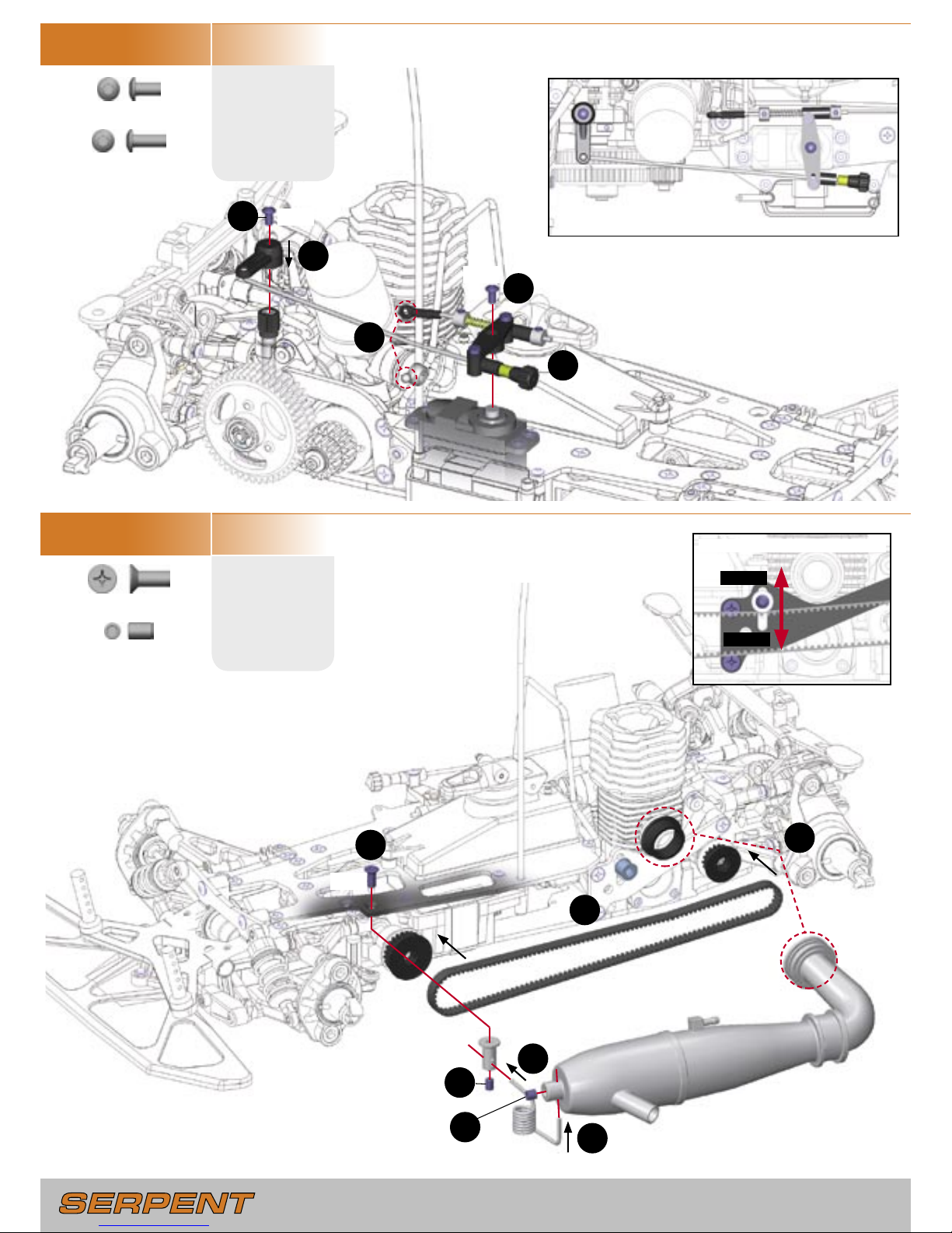
- 28 -
- 29 -
H17
G19
STEP 7.6
BAG 34, G19
G19
M4x10mm
H17
M4x6mm
Side belt tension adjustment
Looser
Tighter
1
2
3
4
5
6
7
STEP 7.5
BAG 34, G19
Completed throttle/brake linkage
E10
M3x6mm
E11
M3x8mm
1
2
4
3
5
E10
E11
OPTION 2: Upright Throttle Servo
Page 29
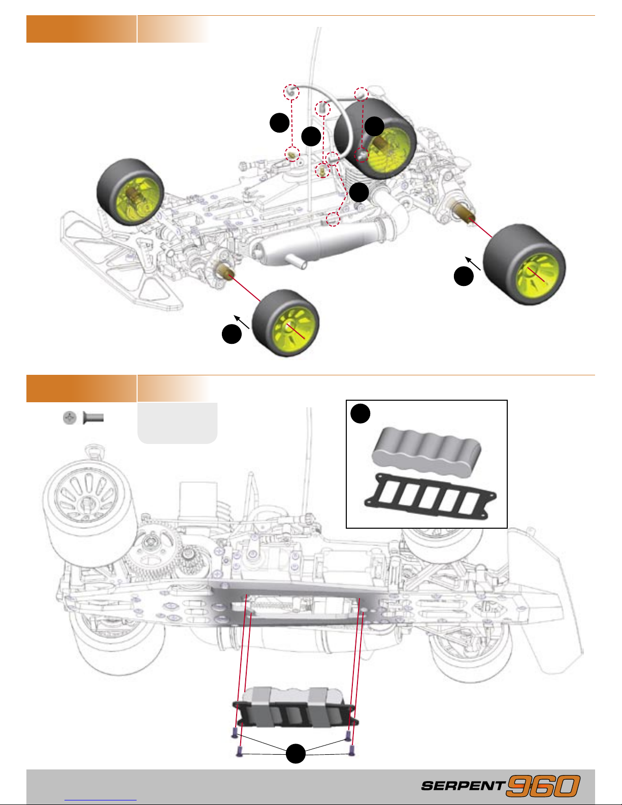
- 29 -
1
1
2
3
2
3
IMPORTANT! Before installation, check
that fuel line and pressure line are free
from debris and not blocked.
Mounted foam tires not included
STEP 7.8
G11
M3x8mm
2
1
Securely attach battery pack
to mounting plate.
G11
G11
G11
G11
STEP 7.7
Page 30
- 30 -
Congratulations, you have completed the building of
your new Serpent 960 !
To prepare your car for its first run, go to the Serpent
960 Setup Book and follow the setup instructions in
Section A: Basic Setup. The setup described there is a
good starting point. After rebuilding the chassis, or in
case you become lost with your setup, always return to
the setup described there.
The Serpent 960 Setup Book also contains detailed
information about the numerous setup possibilities
available on your Serpent 960, prepared by World
Champion Michael Salven.
Page 31

Page 32

Serpent Model Racing Cars BV
PO Box 180, 2100 AD, Heemstede
The Netherlands, Europe
#903147 - Version 1
 Loading...