

Page 1
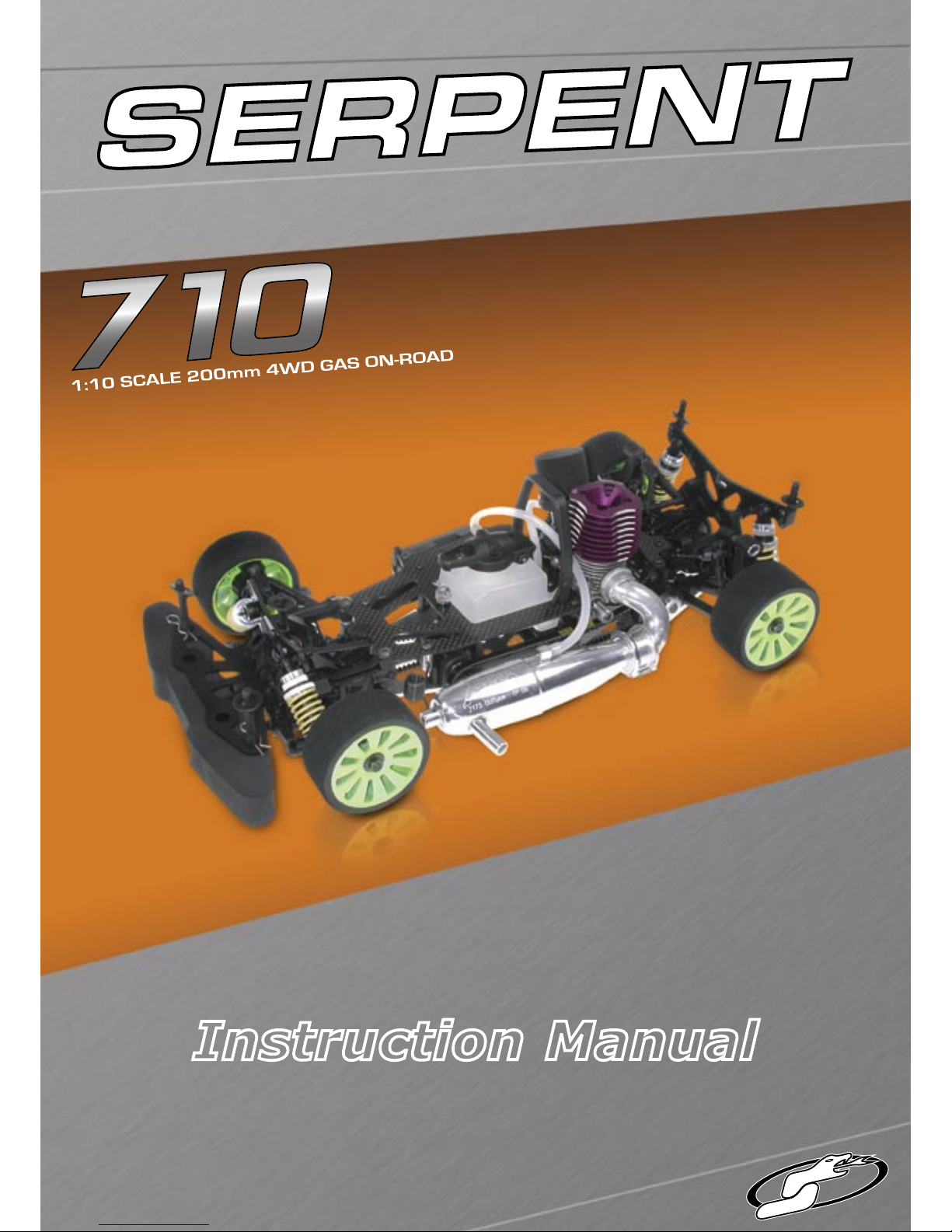
Instruction Manual
Page 2
2
Congratulations on your newly acquired Serpent 710.
You have chosen the highest quality, ultimate-performance 200mm racecar that is easy to use, assemble,
and set up. As part of the worldwide team of Serpent
drivers, you will also get superior technical support.
Serpent has a tradition of excellence with instruction
manuals, and with the new Serpent 710 manual we
have yet again gone a step further. The new layout
has easy to follow step-by-step assembly instructions
and building tips, richly illustrated with 3D rendered
full-color images. Following the instructions will result
in a well-built, high-performance racecar that will soon
be able to unleash its full potential at the racetrack.
Instructions
This instruction manual has nine sections that will lead
you through the assembly process of your Serpent
710. Follow the assembly steps in the order presented
to ensure that no problems occur during assembly.
Each step indicates all the fasteners and small parts
used. Bag numbers are also shown to identify the kit
bag that contains the appropriate parts for the step.
When building your 710, do not empty the parts bags
as you will need to refer to the parts by bag number
several times during the various assembly stages.
Set-up
In certain assembly steps you need to make basic
adjustments, which will give you a good initial setup
for your Serpent 710. Note that fine-tuning the initial
setup is an essential part of building a high-perform-
ance racecar like your Serpent 710. The Set-Up Book
included in your Serpent 710 kit will help you to adjust
your car. It contains detailed information on making
basic settings, as well as in-depth information about
the effect of changing the settings. Be sure to follow
the procedures and be accurate with your adjustments
not only now, but every time you prepare the car for
practicing or racing. This is how the best drivers in the
world do it - simple, straight forward, and accurate!
Exploded views and parts list
The exploded views and parts lists for the Serpent
710 are contained in a separate Reference Guide.
The exploded views show all the parts of a particular
assembly step, together with the Serpent part number.
The parts lists at the end of the Reference Guide indicate the part number and name of each part for easy
reference when re-ordering.
Safety precautions
Included with your Serpent 710 kit is a document entitled “Read This First” that covers safety precautions
for the assembly and use of this product. We strongly
recommend that you thoroughly read and understand
that document, and follow all the precautions.
Section Page
1.0 Front Assembly 4
2.0 Differential Assembly 9
3.0 Rear Assembly 11
4.0 Shock Assembly 16
5.0 Bodymount Assembly 19
6.0 Radio Plate Assembly 21
7.0 Gearbox Assembly 24
8.0 Centax Assembly 26
9.0 Final Assembly 29
Introduction
Contents
PERFORMANCE THROUGH EVOLUTION
Page 3
3
Using the manual
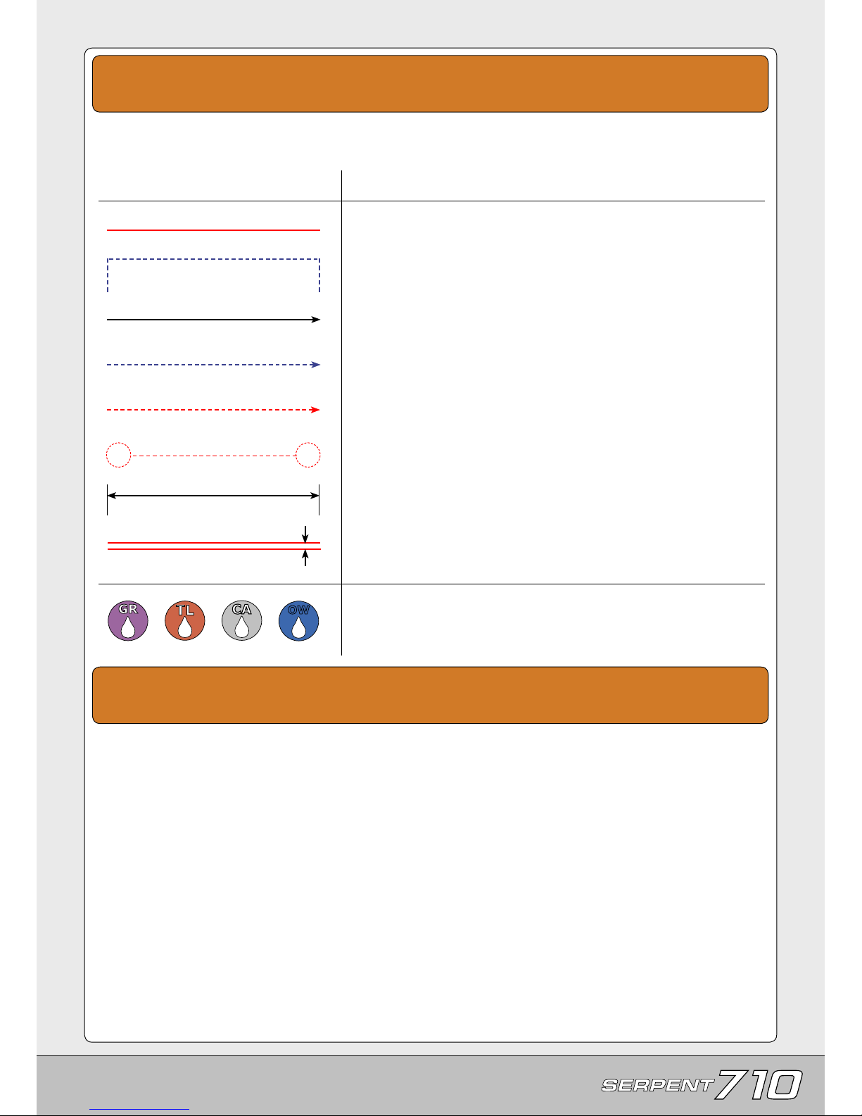
Each step contains a variety of numbers, lines, and symbols. The numbers represent the order in which
the parts should be assembled. The lines and symbols are described below.
Line/Symbol
Description
Assembly path of one item into another.
Group of items (within lines) should be assembled first.
Direction the item should be moved.
Glue one item to another.
Press/Insert one item into another.
Gap between two items.
Apply graphite grease (GR), threadlock (TL), CA glue (CA) or Serpent’s
One-way Lube (OW). (items not included).
myTSN.com
The printed instruction manual included with your
Serpent 710 kit is very complete, though due to
continuous product development, more up-to-date
information is provided at our myTSN.com web
portal. This state-of-the-art R/C technology portal
is where Serpent racers from all over the world
meet and exchange their ideas, and share useful
information and experiences about their Serpent
cars.
All information about the Serpent 710 is accessible from the Serpent 710 product page on
myTSN.com. You can access this page by going to
the Products section, then search for the ‘Serpent
710’ product name.
From the Serpent 710 product page you will find
the very latest information about your Serpent 710:
reports by team drivers and other experts, tips and
tricks, FAQ, forums, setups, image gallery, downloadable files, and even streaming video of the
Serpent 710 on how to further improve the car. The
latest version of the instruction manual (including
team and racer tips, and part lists and option lists)
will be made available as downloadable PDF-files
and online viewable pages under ‘i-Manual’.
So be sure to visit myTSN.com and the Serpent
710 page. There is a world of up-to-date information about your Serpent 710 waiting for you, and it
is just a few mouse clicks away! If you are not yet
a member of myTSN, we strongly recommend that
you sign up immediately so you can experience and
enjoy an even wider range of services from Serpent
and other myTSN partners.
www.myTSN.com/Serpent710
OW
Connect one item to another.
Length after assembly.
Page 4
4
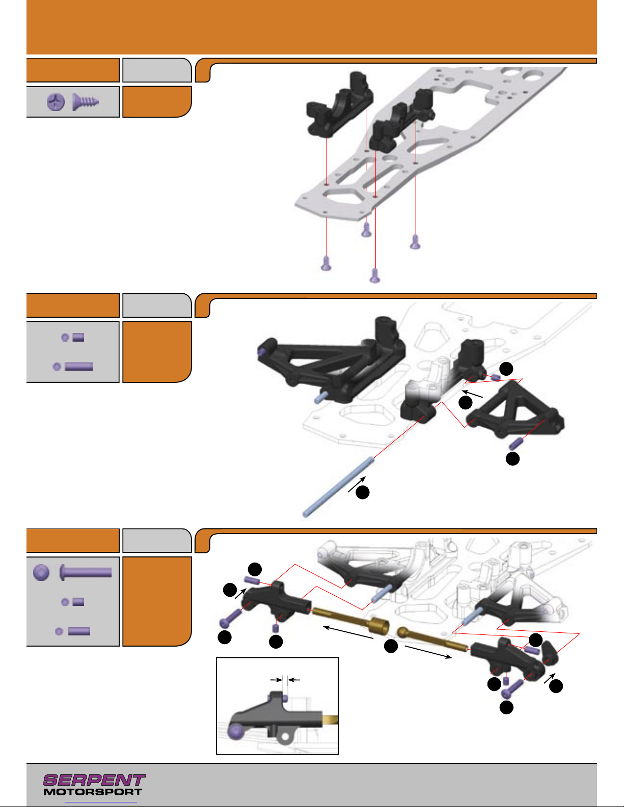
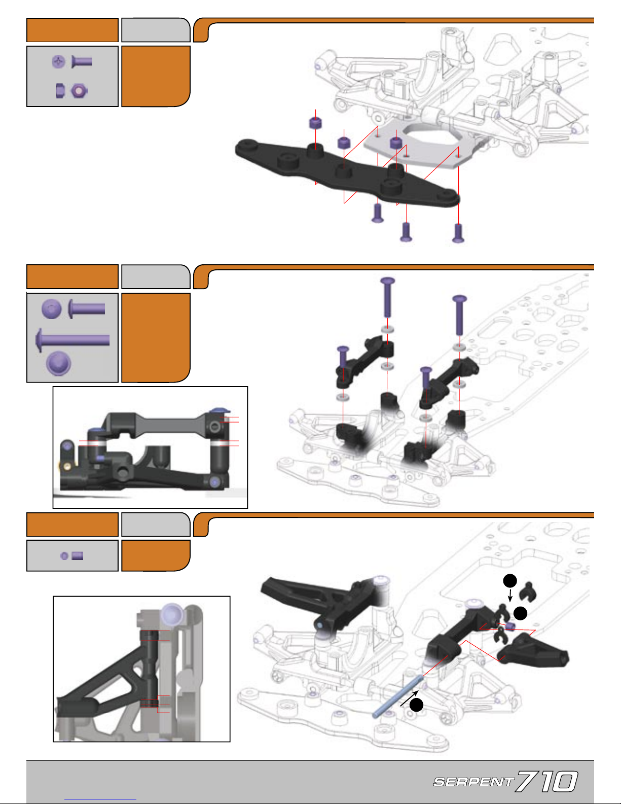
Step 1.1
Bag 06,
16, B12
B12
3.5x9.5mm
E14
3x16mm
1.0 Front Assembly
Step 1.2
Step 1.3
3
2
4
1
1
3
5
2
2
5
4
4
3
Assemble both front lower arms
using the indicated steps.
2mm
IMPORTANT!
Adjust both left
and right upstop setscrews
equally, otherwise the car may
become tweaked under braking.
H12
3x10mm
H9
3x4mm
H9
3x4mm
H11
3x8mm
Bag 02, 15
Bag 04
B12
B12
B12
B12
H9
H12
H11
E14
H9
H11
E14
H9
Page 5
G11
3x8mm
5
Step 1.4
Step 1.5
Step 1.6
3
2
1
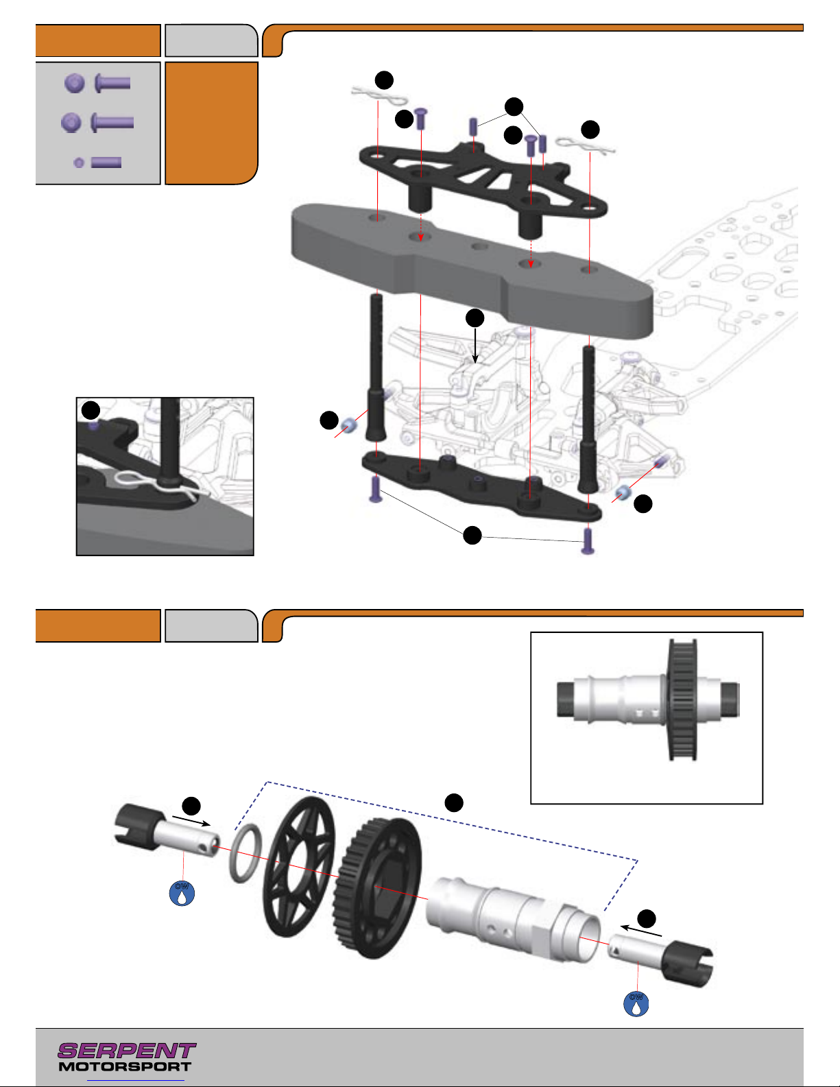
Assemble both front upper arms
using the indicated steps.
Default placement of front roll
center alu spacers
4mm
2mm
1mm
Caster Spacer Placement
<
>
L3
M3
E20
4x12mm
EF23
4x25
Bag 06, 17
H9
3x4mm
Bag 02, 15
G11
G11
G11
L3
L3
L3
EF23
EF23
E20
E20
H9
Dont tighten screws EF23. They
will be removed in step 6.7.
<
Page 6
6
Step 1.7
Step 1.8
2
3
4
4
5
6
6
1
2
2
OW
OW
1
1
6
E11
3x8mm
E12
3x10mm
Bag E11,
E12
H11
3x8mm
Bag 11, 18
35T
E11
E11
H11
H11
E12
E12
It is possible to lock the front axle using
the option set #802252
Page 7
7
E12
3x10mm
U13
12x18mm
E10
3x6mm
Step 1.9
Step 1.10
Step 1.11
Bag E10,
U, 19
3
1
1
2
4
2
1
1
5
3
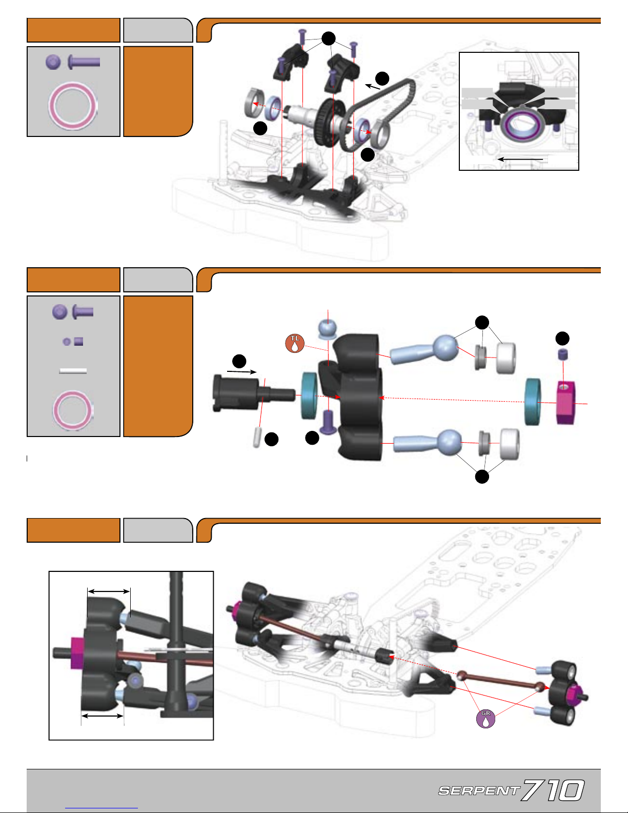
Change the position of BOTH
eccentric hubs to adjust front
belt tension. Both hubs should
have the same position.
Assemble both steering blocks
using the indicated steps. Left
steering block shown.
Do not overtighten alu plugs. Pivotballs should
move freely without binding or excessive play.
Assemble both steering
blocks as shown.
IMPORTANT!
Ensure the front suspension
moves up and down freely without binding.
17mm
16.5mm
Looser
Loose
Tighter
Default
Bag U, E12,
07, 13
H8
3x3mm
P1
2x10mm
U11
10x15mm
E12
E12
E12
E12
U13
U13
U11
P1
U11
H8
E10
Front
Rear
Page 8
8
B5
2.9x9.5mm
U6
6x13mm
B5
2.9x9.5mm
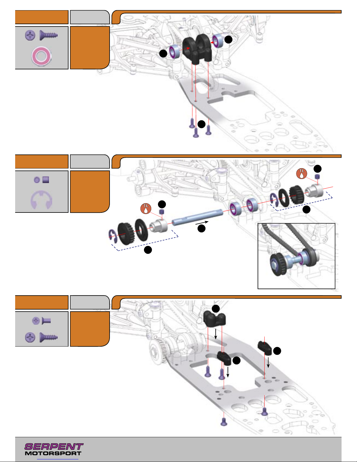
Step 1.12
Step 1.14
Bag U, 20
Bag 10
H16
4x4mm
R7
7mm
Step 1.13
Bag 12
2
1
1
2
1
4
5
3
1
2
2
22T
19T
U6
U6
B5
B5
B5
R7
R7
H16
H16
B5
B5
G10
G10
G10
3x6mm
Page 9
9
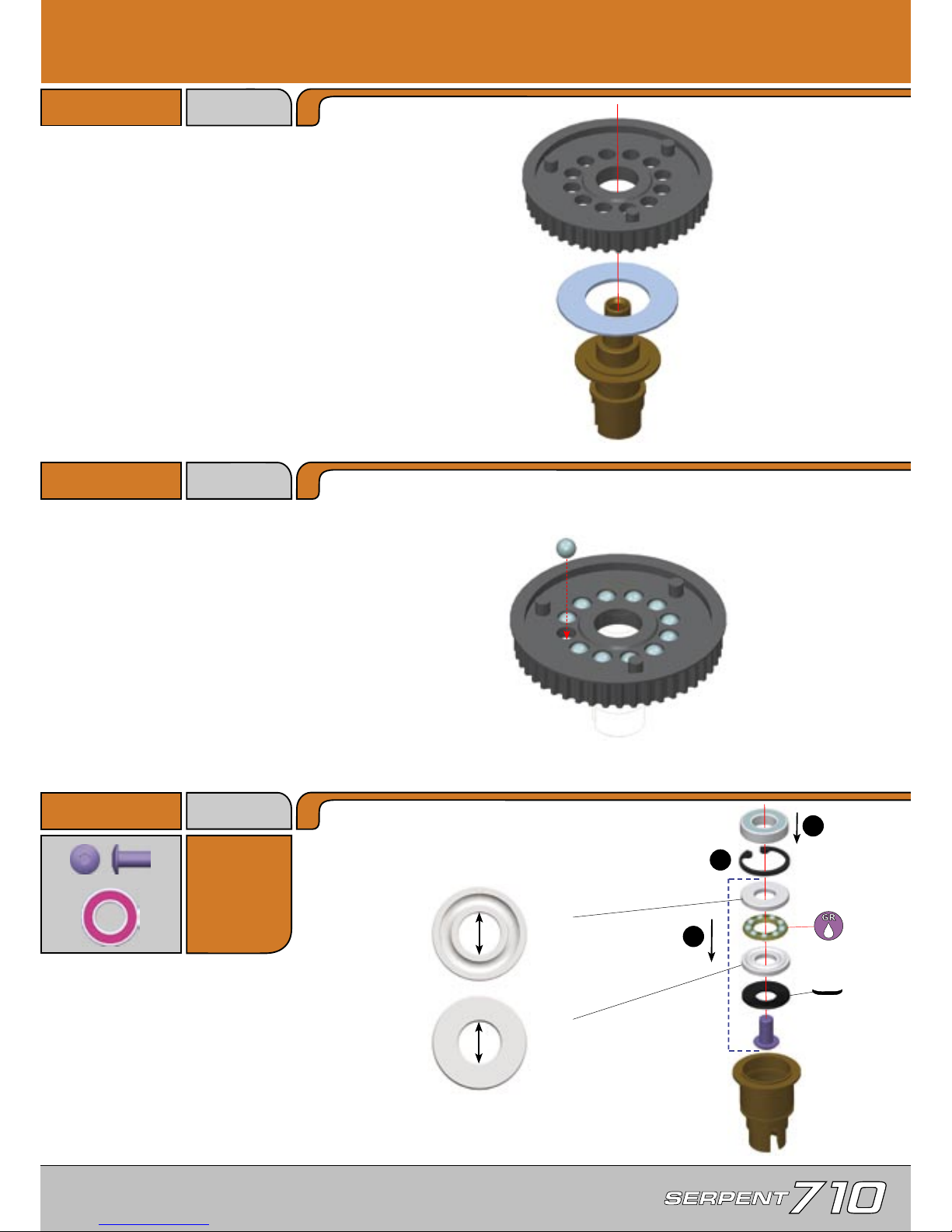
2.0 Differential Assembly
Step 2.1
Step 2.2
Bag 11, 21
E18
4x8mm
Step 2.3
Bag U
U7
7x14mm
6mm
6.2mm
A
B
1
2
3
45T
U7
E18
Page 10
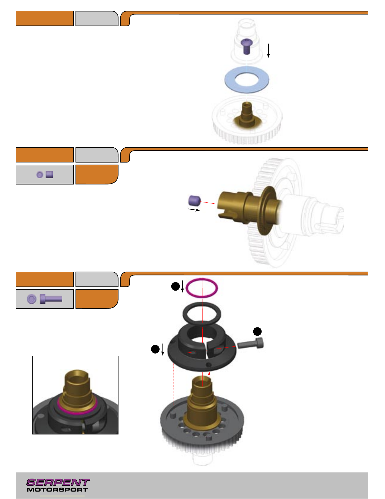
F12
3x10mm
10
Step 2.4
Step 2.5
Step 2.6
H16
4x4mm
3
1
2
Differential Adjustment
Adjust the diff friction collar to adjust
the differential action. Tighten the
adjustment screw to increase the
spin-resistance of the differential;
loosen the adjustment screw to
reduce the spin-resistance of the dif
ferential. The tighter the diff collar,
the more the differential resists the
difference in speed between the inner
and outer wheel. As a rule of thumb,
the more grip a track has, the tighter
the diff collar should be.
Use this screw to apply pre-load
to the differential. Tighten it so
that the diff pulley doesn’t slip
while holding both diff shafts but
still turns as freely as possible.
Tighten this locking setscrew to
lock your initial setting.
Bag 22
H16
F12
Page 11
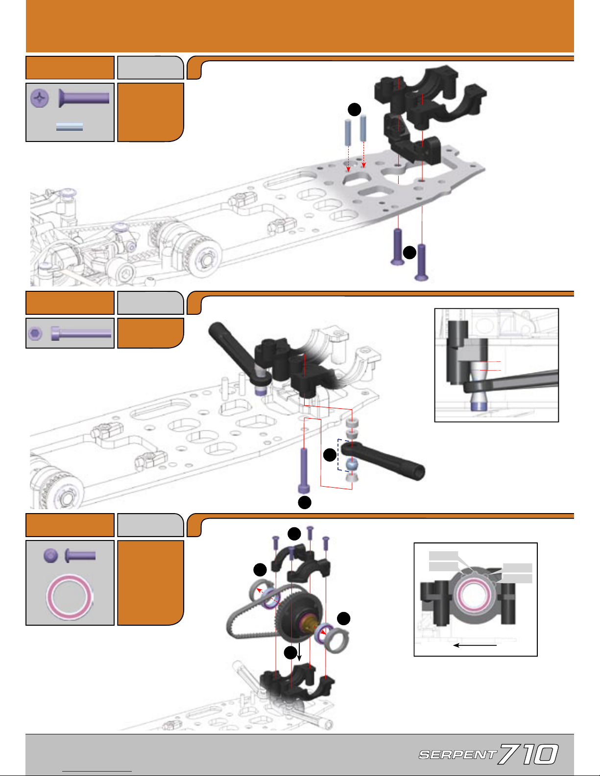
11
G22
4x20mm
F15
3x20mm
3.0 Rear Assembly
Q11
3x10mm
Step 3.1
Step 3.2
Bag 05, 08
Bag 23
E12
3x10mm
Step 3.3
Bag 07,
13, U
U13
12x18mm
2
1
2
1
3
1
1
2
Assemble both lower arms using
the indicated steps.
Press pins into chassis so they
are flush with bottom.
Default position of Dynamic Rear
Steering (DRS) spacer.
Press ball into end of arm
until it snaps into place.
Change the position of BOTH
eccentric hubs to adjust rear
belt tension. Both hubs should
have the same position.
<
Tighter
Default
Loose
Looser
G22
G22
Q11
Q11
F15
E12
E12
E12
E12
U13
U13
Front
Rear
Page 12
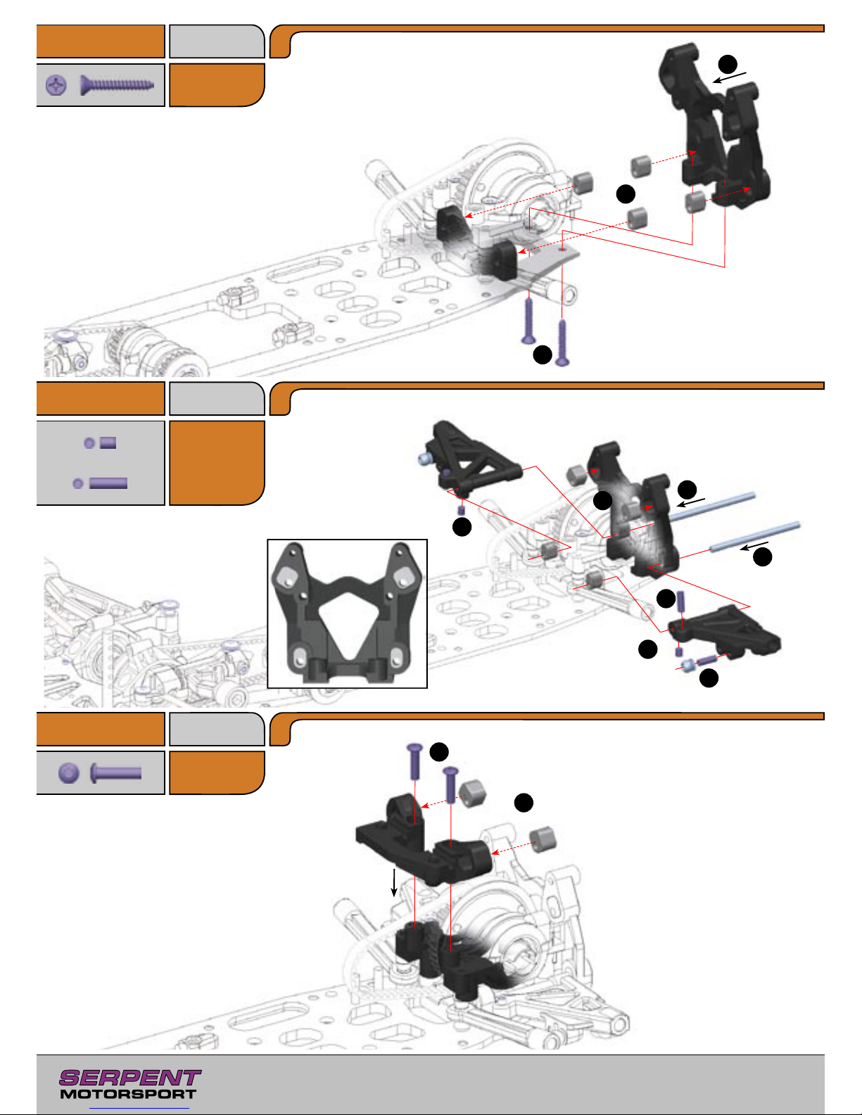
12
B8
2.9x19mm
E13
3x12mm
Step 3.4
Step 3.5
Step 3.6
Bag 08, 13
Bag 05
H9
3x4mm
1
2
3
2
3
5
4
4
1
5
1
2
Note the orientation of the inserts.
Ensure that all four inserts are the same.
Note the orientation of the
inserts.
Note the orientation of the two inserts.
Ensure that both inserts are the same,
and are oriented the same as the
matching inserts.
Bag 09,
15, 24
H12
3x10mm
B8
B8
H9
H9
H12
H12
E13
E13
Use the outer position
Page 13
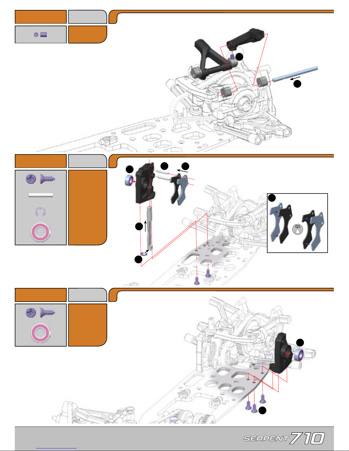
13
H9
3x4mm
B12
3.5x9.5mm
Step 3.7
Step 3.8
Bag 09, 15
Bag 03,
U, B12
P7
2.5x16mm
B12
3.5x9.5mm
Step 3.9
U6
6x13mm
1
2
3
2
6
1
1
2
5
4
Assemble both rear upper arms using
the indicated steps.
Roughen metal plates with
sandpaper before gluing.
Press pins into bulkhead until ends
are flush with outer edge.
R3
3mm
U6
6x13mm
H9
U6
R3
P7
B12
B12
B12
B12
B12
U6
Page 14
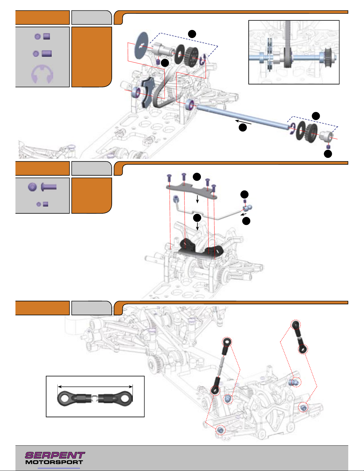
14
H17
4x6mm
Step 3.10
Step 3.11
Step 3.12
Bag 12, 25
E11
3x8mm
3
1
2
4
5
4
1
2
3
Adjust ball end until it is ush
with end of swaybar.
48mm
1:1
R7
7mm
H16
4x4mm
Bag 14, 26
H8
3x3mm
22T
24T
R7
R7
H17
H16
E11
E11
E11
E11
H8
Page 15
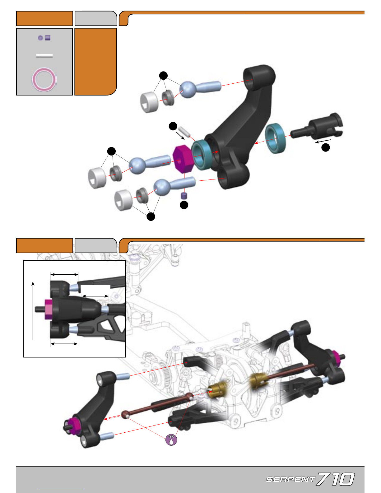
15
Step 3.13
Step 3.14
H8
3x3mm
P1
2x10mm
1
1
1
4
3
2
Assemble both rear hubs
using the indicated steps.
Do not overtighten alu plugs.
Pivotballs should move freely
without binding or excessive play.
Assemble both rear hubs
using the indicated steps.
IMPORTANT!
Ensure the rear suspension moves up
and down freely without binding.
19mm
19.5mm
18.5mm
Front
Rear
Bag 01,
27, U
U11
10x15mm
U11
U11
P1
H8
Page 16
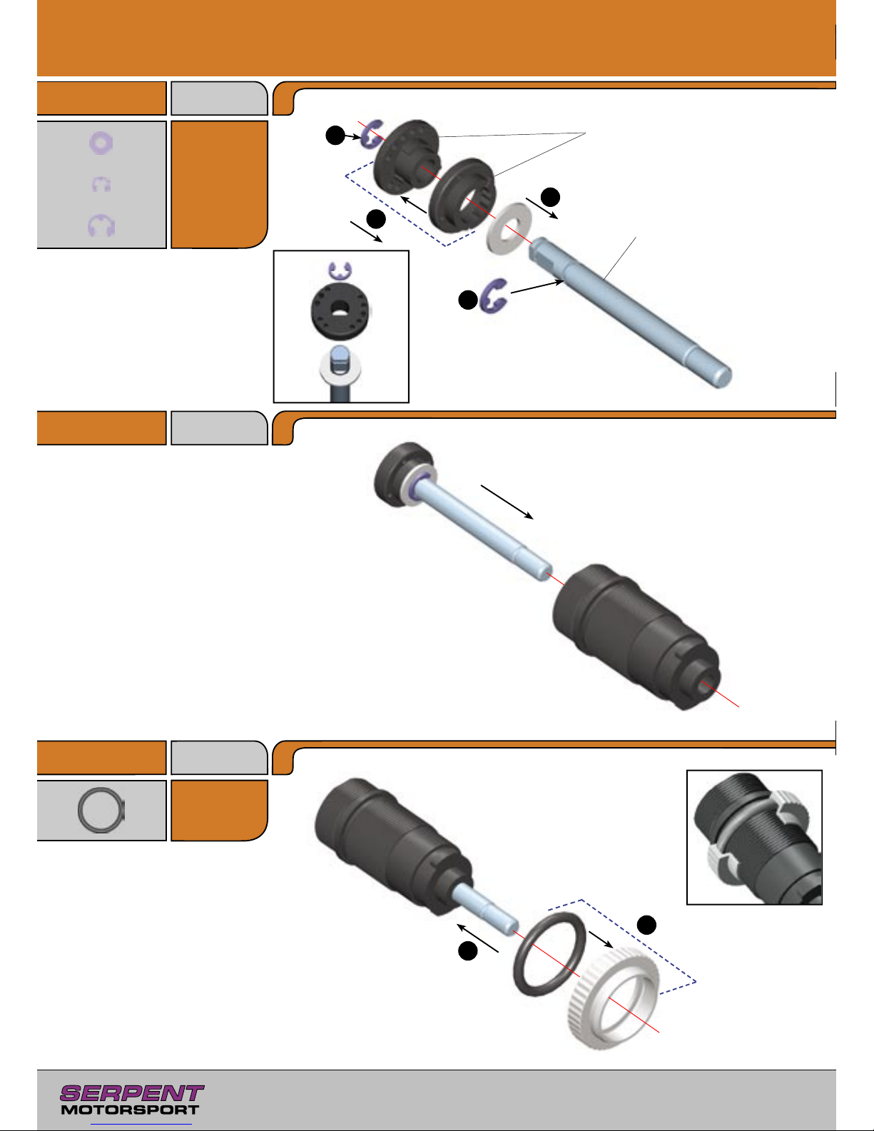
16
Step 4.1
Bag 28
R1
1.9mm
N3
3x6mm
R2
2.3mm
Y17
12.1x1.6mm
4.0 Shock Assembly
Front shocks: short shock shaft and body
Rear shocks: long shock shaft and body
Remove plastic flashing for smooth
movement of pistons. Tab in upper piston
fits in notches in lower piston
R2
N3
4
R1
Y17
3
2
1
2
1
Step 4.2
Step 4.3
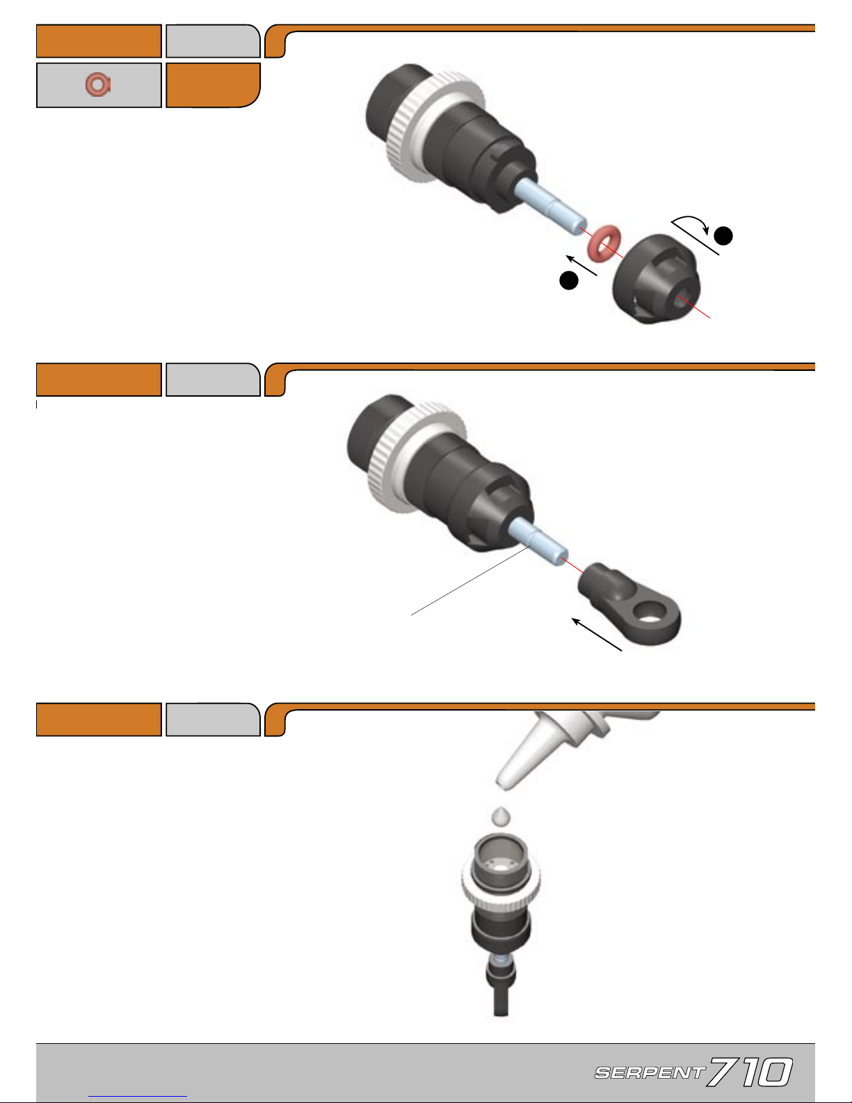
Lubricate shock shaft with shock oil
before inserting in shock body.
Page 17
17
Y3
3x1.5mm
Fill the shock body with shock oil, with the piston at
the bottom.
Bleeding
Let the oil settle and allow the air to escape. Slowly
move the piston up and down to release any trapped
air bubbles. Repeat as necessary until no bubbles
appear.
Use a shock rod gripping tool, or grip the shock rod
at top of exposed threads with side cutting pliers. Be
sure not to damage the shock rod.
Y3
Step 4.4
Step 4.5
Step 4.6
1
2
Lubricate O-ring with shock oil before
sliding onto shock shaft.
Hint:
Pre-thread balljoint with M3 screw for
easy assembly
Page 18
18
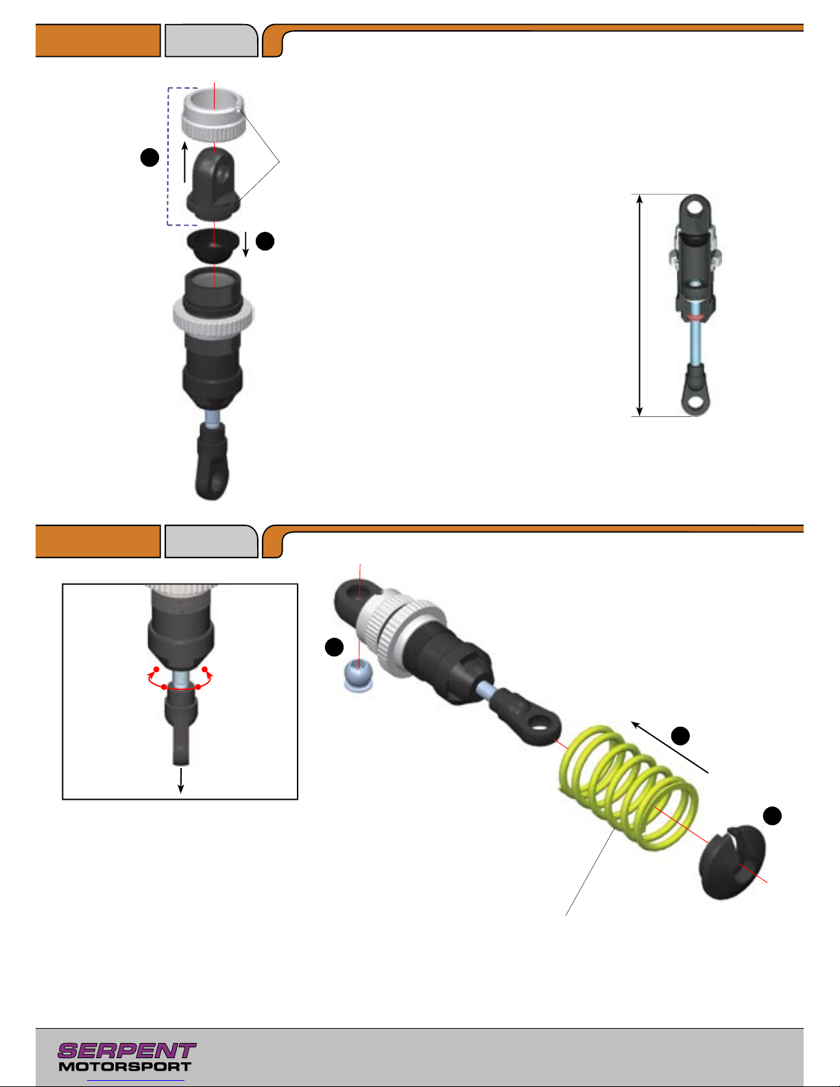
Front Shocks: short shocks and springs
Rear Shocks: long shocks and springs
Hardest
Full CW
Softest
Full CCW
Damping adjustment
Pull the shock shaft all the way out, turn
slightly to lock it in the shock body.
Adjust the shock damping by rotating
shock shaft CW or CCW to one of the
four positions. Each position can be felt by
a slight “click.”
IMPORTANT!
Each pair of front and rear
shocks must have the same damping set
-
ting.
Shock length adjustment
Check the length of the shocks in the
extended, fully locked position.
Front shocks: 67.5mm
Rear shocks: 76.5mm
Adjust shock length with the balljoint.
IMPORTANT!
Each pair of front and
rear shocks must be the same length.
Line up
notch
Step 4.7
Step 4.8
1
2
2
3
2 Holes
3 Holes4 Holes
5 Holes
1
Press in pivotball from
side opposite notch in top
shock mount.
Page 19
19
E11
3x8mm
5.0 Bodymount Assembly
E12
3x10mm
Step 5.1
Bag 14,
29, E11
E10
3x6mm
Step 5.2
1
1
2
2
3
1
2
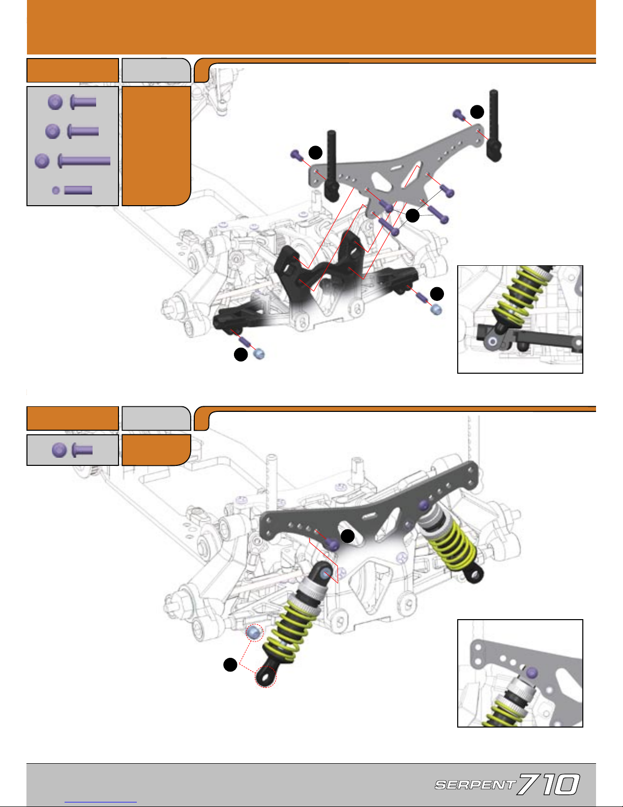
Upper shock default mounting
position
Lower shock default mounting
position
E29
3x18mm
H12
3x10mm
H12
E11
E11
E12
E29
E12
E29
H12
E10
Bag E10
Page 20
20
Step 5.3
Step 5.4
1
2
1
2
E10
3x6mm
E11
3x8mm
G12
3x10mm
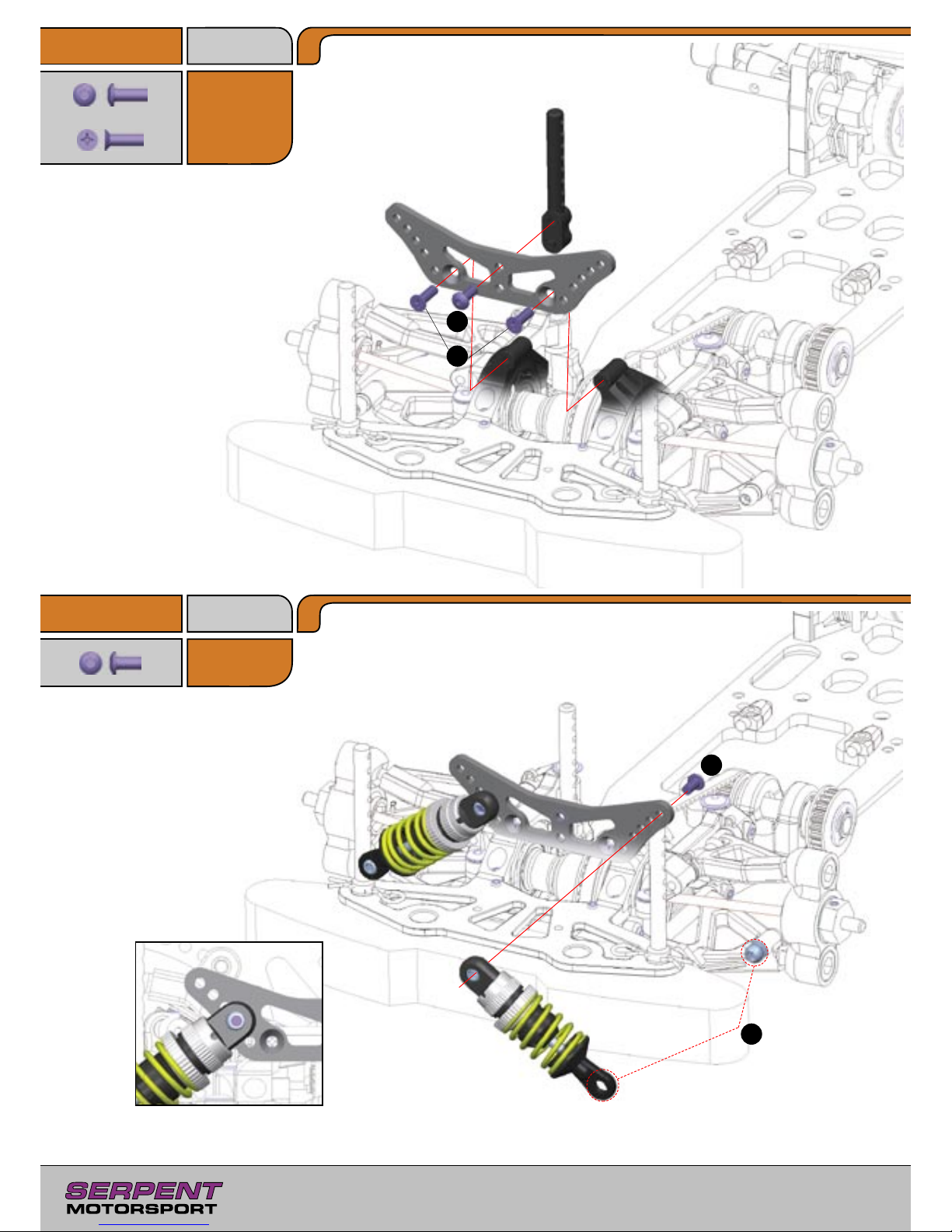
Upper shock default mounting
position
Bag E11
Bag E10
G12
G12
E11
E10
Page 21
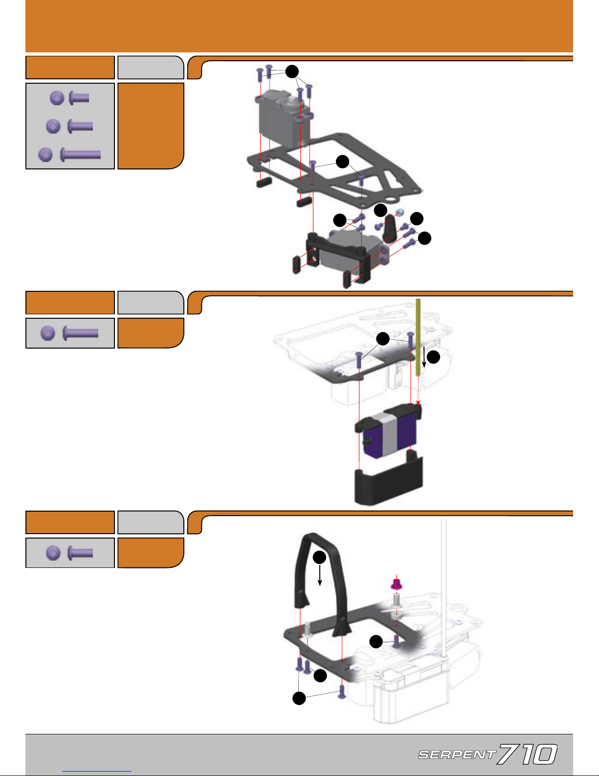
21
E10
3x6mm
E13
3x12mm
6.0 Radio Plate Assembly
Step 6.1
Bag 10, 14,
30,E10, E11
Step 6.2
E11
3x8mm
E11
M3x8mm
Step 6.3
Bag E11
1
2
3
3
5
4
1
2
4
3
1
2
Steering Servo
Output gear of steering servo must
be towards the FRONT of car.
Throttle Servo
Output gear of throttle servo must
be towards the FRONT of car.
The number on the servo arm corresponds
to the number of teeth.
23 - Sanwa / KO / JR
24 - Hitec
25 - Futaba
Securely attach receiver to mounting plate.
Route antenna wire up through antenna
mounting hole, and through antenna tube.
E13
3x12mm
E13
E13
E13
E13
E13
E13
E13
E10
E10
E11
E11
E13
E13
E11
E11
E11
E11
Page 22
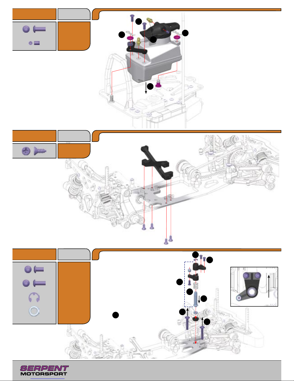
22
E11
3x8mm
B12
3.5x9.5mm
Step 6.4
Step 6.5
E10
3x6mm
E11
3x8mm
R4
4mm
Step 6.6
2
3
5
4
1
4
3
2
1
1
6
5
For clockwise circuits with mostly right
hand corners the fuel tank lid nipple
should be placed on the right side of the
lid and the grubscrew on the opposite
side. The opposite is true for anti clock
-
wise tracks with mostly left hand corners.
Important!
Check that the fuel line and
pressure line are free from debris and not
blocked
Remove screws, but leave spacers
in place atop front bulkheads.
1
Correct orientation of
finished servo saver
Front
Rear
Bag 31, E11
Bag 03,
B12
Bag 04, 32,
U, E10, E11
E11
E11
H9
H9
3x4mm
B12
B12
B12
B12
U3
E10
E11
U3
5x8mm
R4
Note: The fuel tank is equipped with
a mounting point where shims can be
mounted in the tank to make the vol
-
ume exactly 75cc.
For important races always have the
volume of your fuel tank checked.
Page 23
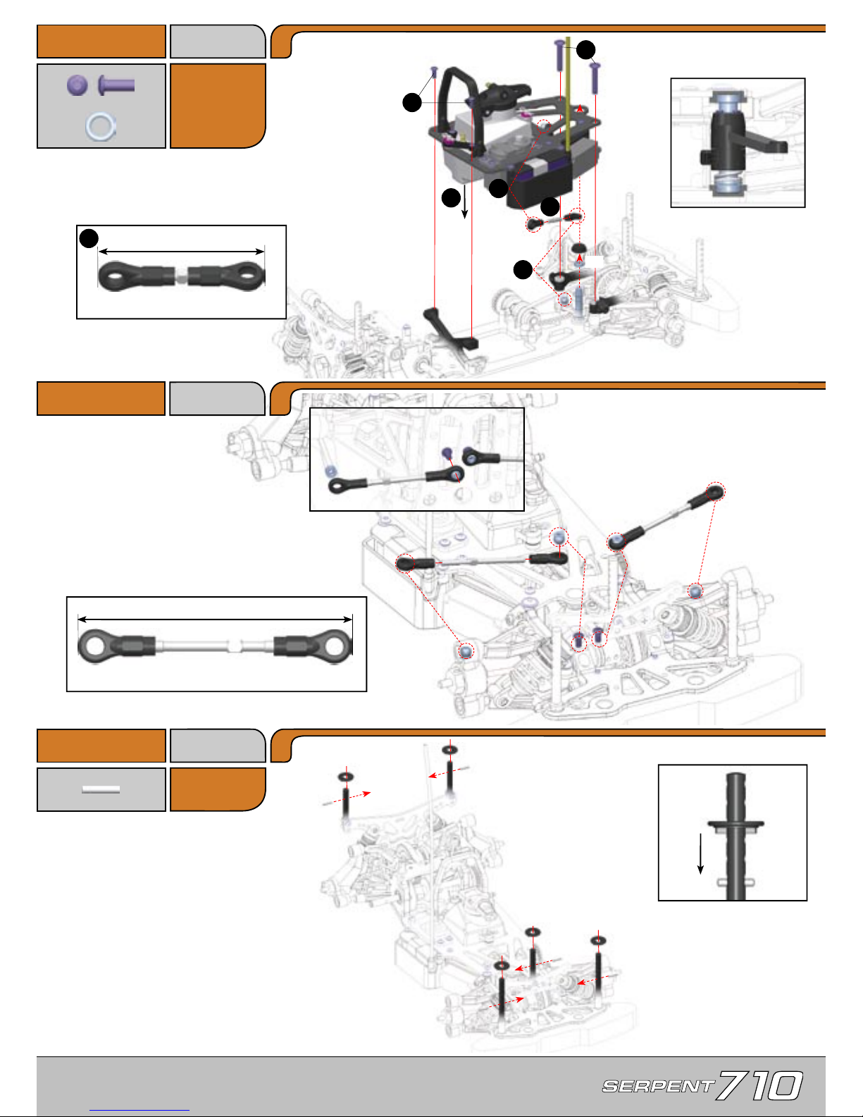
23
E11
3x8mm
U3
5x8mm
Step 6.7
P1
2x10mm
Step 6.9
Step 6.8
4
5
6
1
3
2
44.5mm
1:1
72mm
1:1
1
Position the metal pin at
the desired body mount
ing height and then press
the plastic collar down
until it clips into place.
Correct orientation of
mounted servo saver
Left and right track rods are the same length
E11
E11
U3
P1
P1
P1
P1
P1
Bag E11
Steering rod length
Page 24
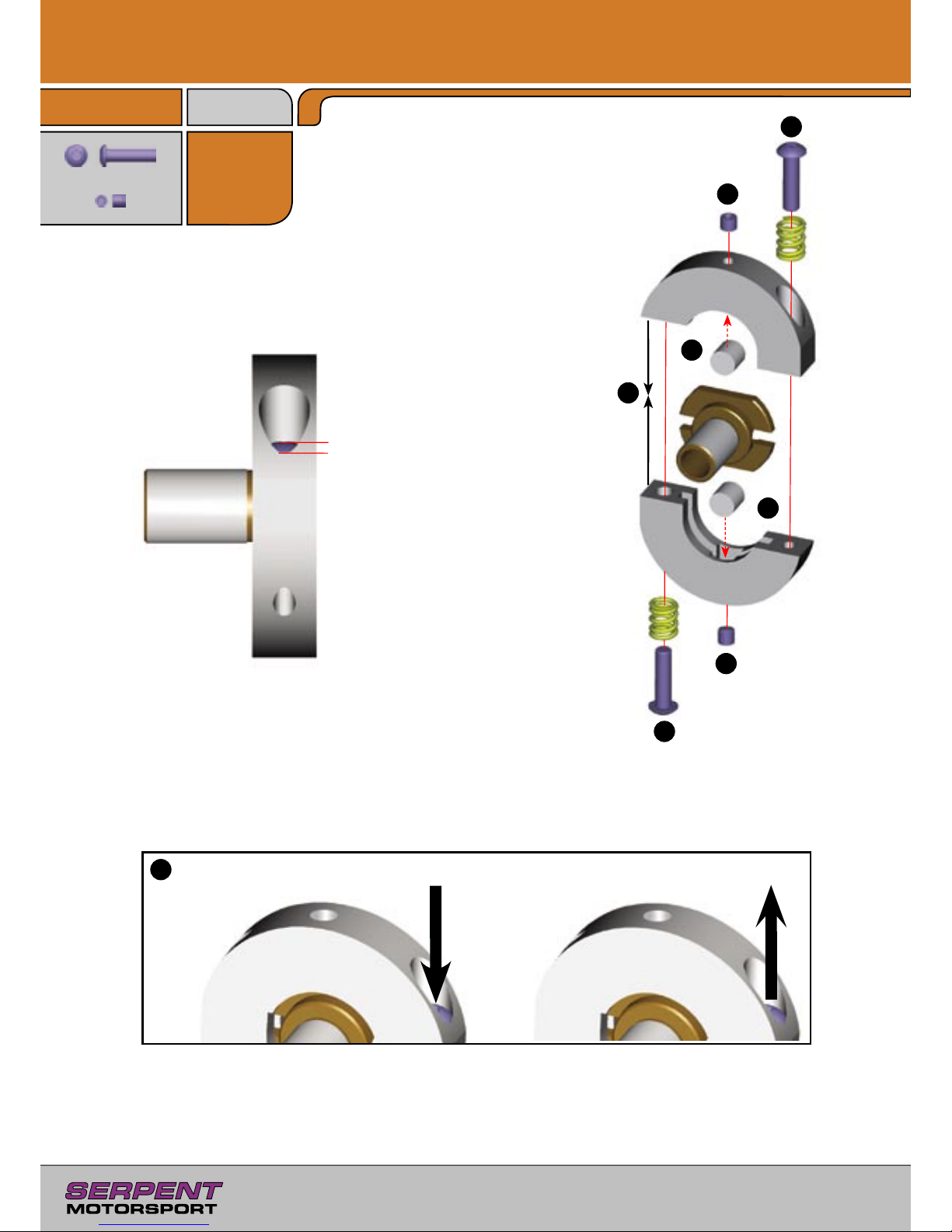
24
E13
3x12mm
7.0 Gearbox Assembly
Step 7.1
Bag 33
H8
3x3mm
1
1
4
4
3
3
3
2
Note:
A good starting point is to
have the screw head flush with
the bottom edge of the hole.
Make sure both screws are set
equally.
E13
E13
H8
H8
Screw IN both adjusting screws
to shift LATER.
Screw OUT both adjusting screws
to shift EARLIER.
Page 25
25
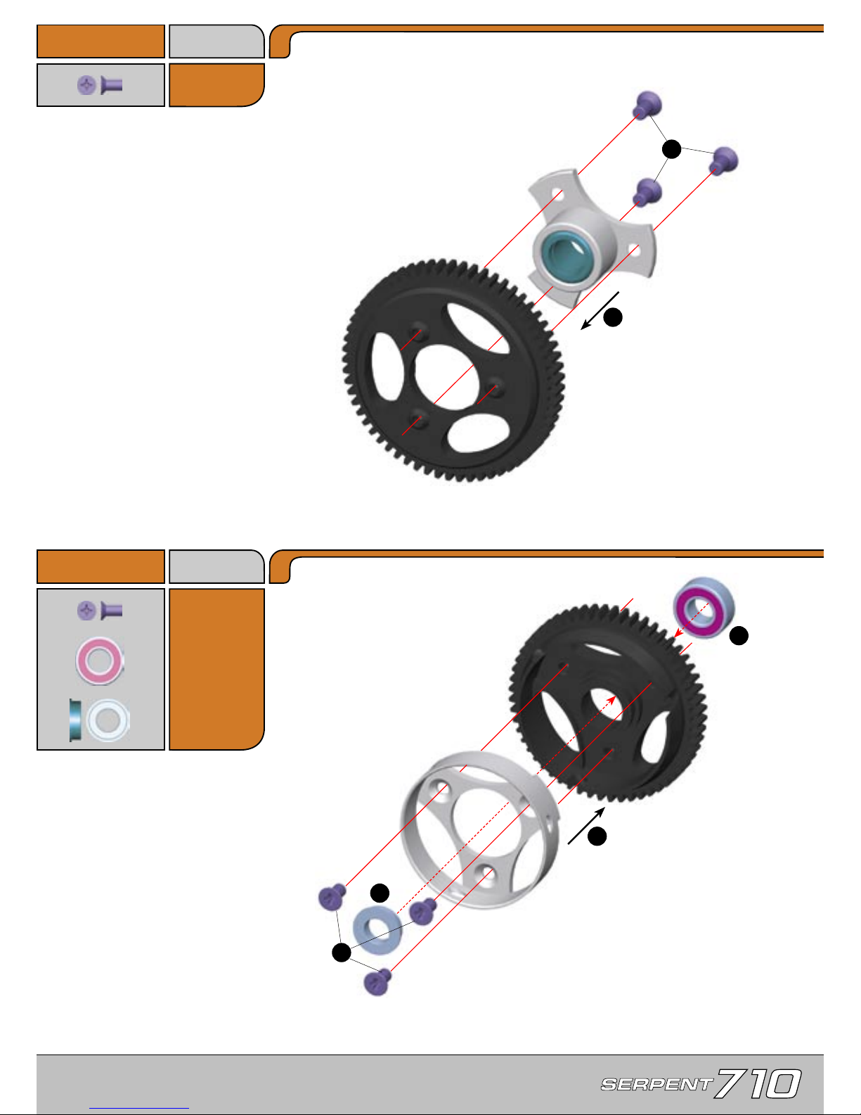
G10
3x6mm
Step 7.2
G10
3x6mm
U6
6x13mm
V5
6x10mm
Step 7.3
1
2
1
2
2
3
Bag 34
Bag U
G10
V5
U6
60T
56T
G10
G10
G10
G10
G10
Page 26
26
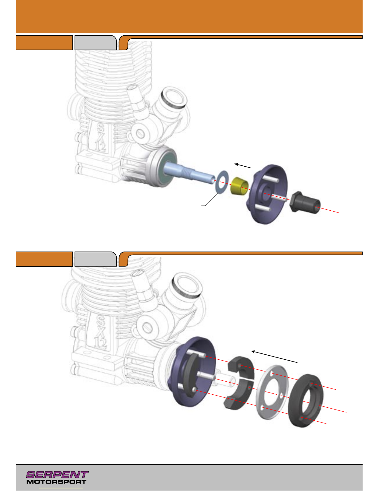
8.0 Centax Assembly
Step 8.1
Bag 35
Step 8.2
0.5mm
Page 27
27
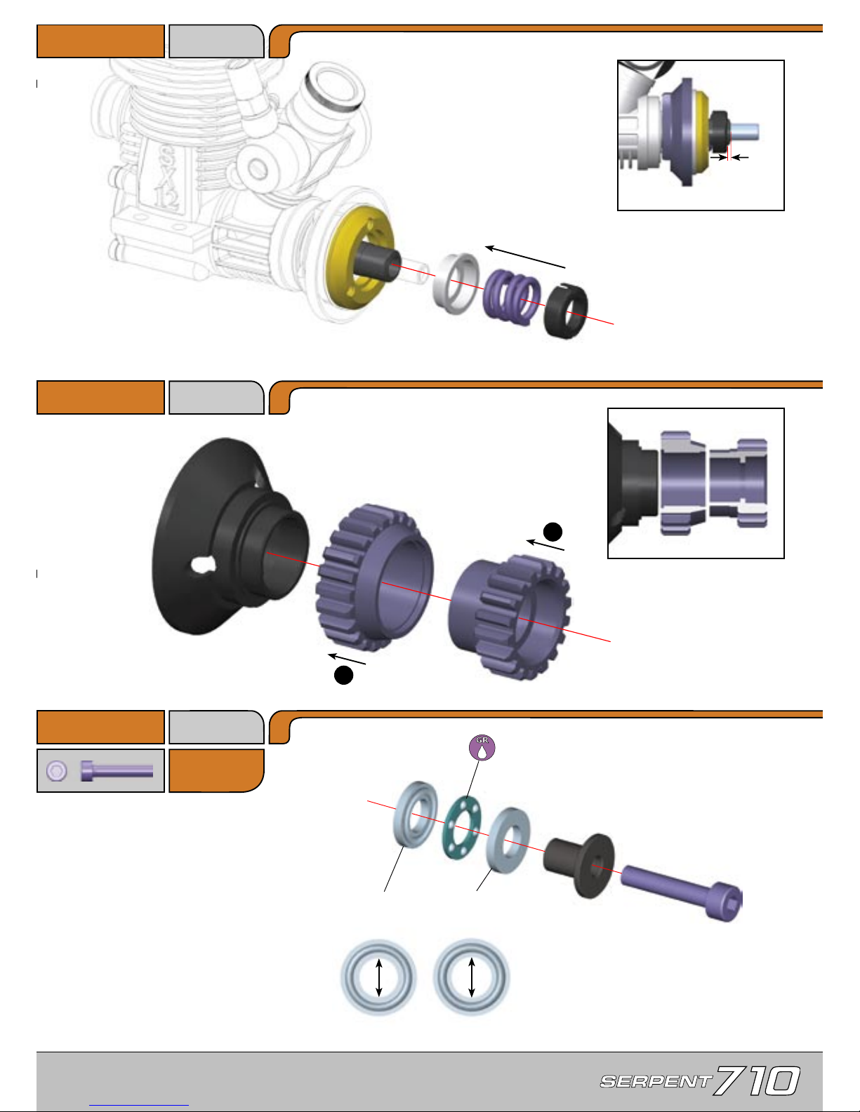
F14
3x16mm
Step 8.3
Step 8.4
Step 8.5
5.2mm
5mm
B
A
F14
Larger inner dia.
Smaller inner dia.
1mm
Bag 36
22T
17T
1
2
Page 28
28
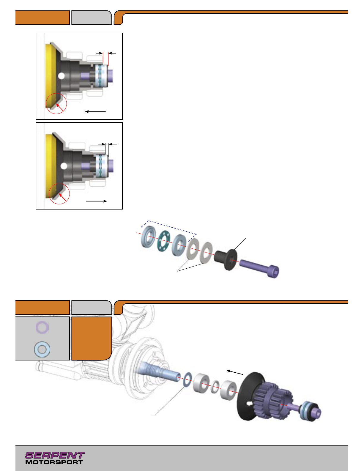
M11
5x8x0.1mm
5x8x0.3mm
Step 8.6
Step 8.7
Bag U
Adjusting the clutch gap
Install only the clutchbell and the thrustbearing assembly on the engine crankshaft.
Push the clutchbell onto the clutch shoe, and then measure the distance A as indicated.
Pull the clutchbell away from the clutch shoe, and then measure the distance B as indicated.
The clutch gap is A – B; the correct gap is 0.7mm.
If the clutch gap is greater than 0.7mm, you can easily calculate the thickness of shims
required to set the correct gap:
Thickness of shims required (in mm) = A – B – 0.7
For example, using the values A=1.3mm, B=0.3mm
Shim thickness = 1.3 – 0.3 – 0.7 = 0.3mm
Place shims between the outer thrustbearing plate and the rim of the thrustbearing carrier as
shown.
A
B
Shims
Thrustbearing
Thrustbearing carrier
Pull
Push
Add small shims to allow only
small amount of endplay.
U4
5x10mm
M11
U4
U4
Page 29
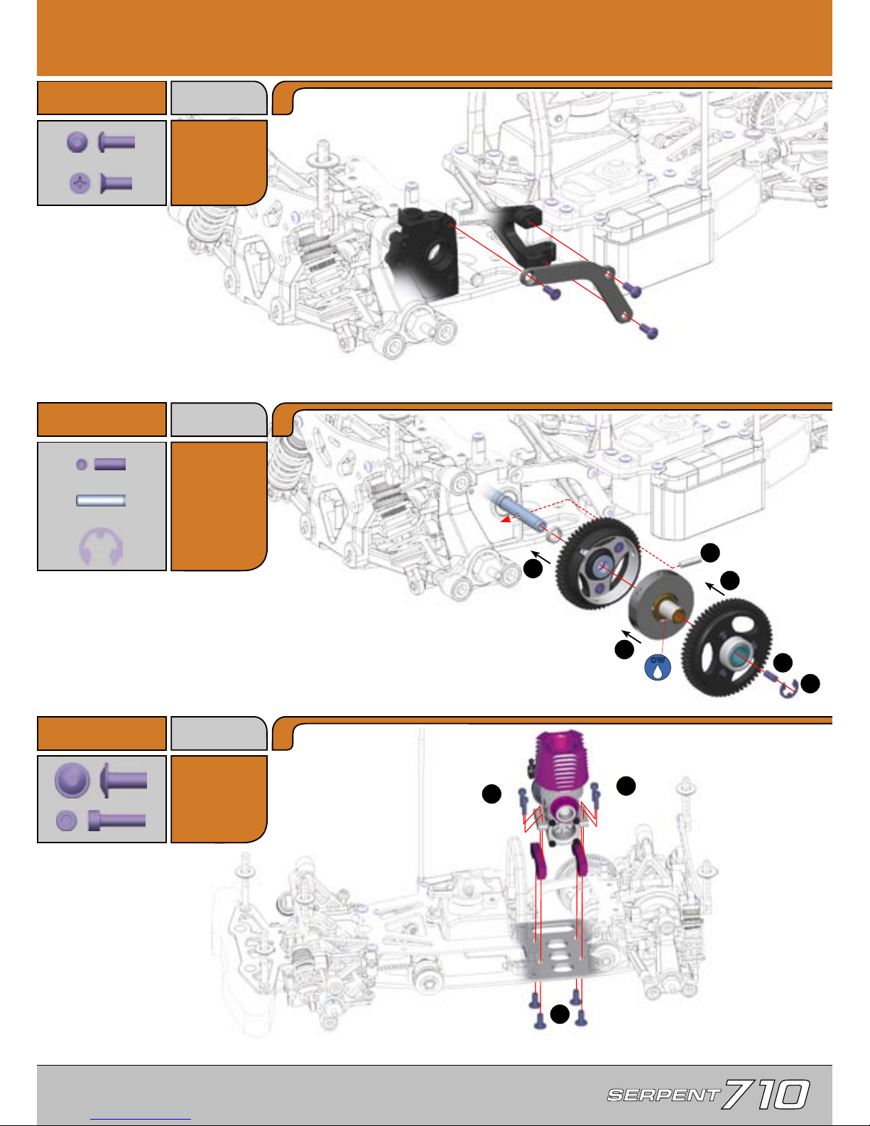
29
E11
3x8mm
H11
3x8mm
9.0 Final Assembly
Step 9.1
Bag 14,
37, E11
Step 9.2
G11
3x8mm
EF19
4x10mm
Step 9.3
1
2
3
4
6
2
1
1
Adjusting the 2-speed shoe gap
Loosen the gap-setting setscrews (H8 in step 7.1) to allow
the shoes to rest on the drive adaptor.
Install the 2-speed shoes in the 2nd gear carrier, but do NOT install the 1st gear.
There should be equal but minimum spacing between the 2-speed shoes and the 2nd gear carrier.
Tighten BOTH gap-setting setscrews until the shoes touch the inside surface of the aluminum 2nd
gear carrier, then loosen BOTH screws by 1/2 turn each. The 2nd gear carrier should spin freely.
Install the 1st gear.
OW
F13
3x12mm
G11
E11
E11
P13
R5
EF19
EF19
EF19
EF19
F13
F13
F13
F13
R5
5mm
P13
3x14mm
5
H11
Page 30
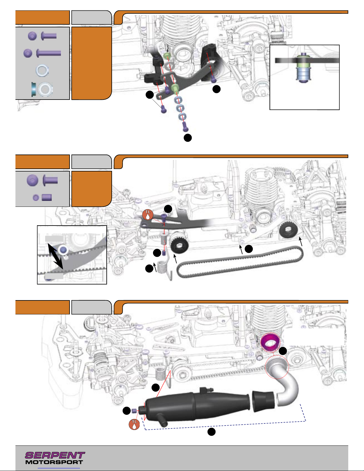
30
E11
3x8mm
E28
3x14mm
E18
4x8mm
H17
4x6mm
Step 9.4
Step 9.5
Step 9.6
1
2
2
1
4
2
3
2
3
4
1
Orientation of belt tensioner
bearings
Looser
Tighter
Side Belt Tension Adjustment
Assemble pipe to the correct length.
Secure exhaust header to
engine using appropriate
springs (not included).
Bag 14, 38
E11, U
U3
5x8mm
V3
5x8mm
Bag 39
E28
E11
E11
E11
V3
V3
U3
H17
E18
Page 31
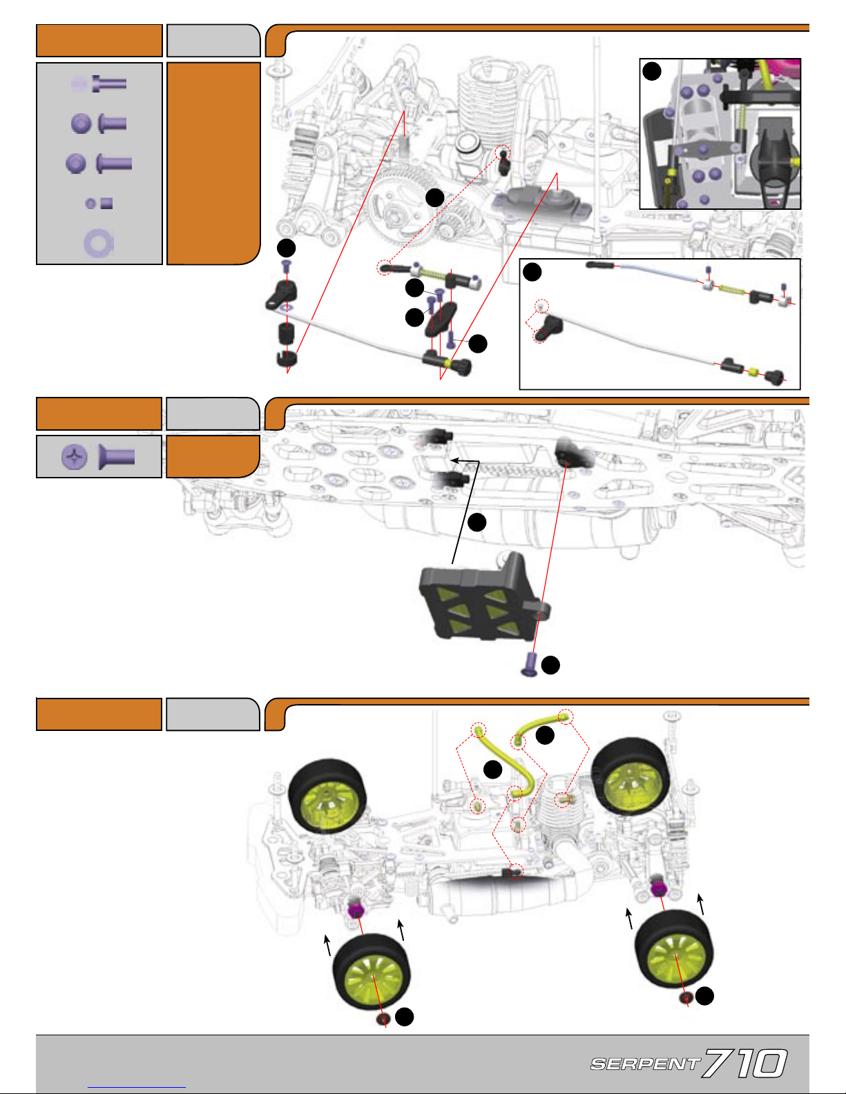
31
C5
2.5x8mm
E10
3x6mm
Step 9.7
G19
4x10mm
Step 9.8
Step 9.9
1
2
2
3
1
1
Securely attach a AAA 5-cell receiver
battery pack to the battery tray.
Note: Serpent offers the pre-built
5-Cell battery set (#801173) for the
Serpent 710. For more information,
see the appropriate product page on
myTSN.com
Front tires (narrow)
Rear tires (wide)
The number on the servo
arm corresponds to the
number of teeth.
23 - Sanwa / KO / JR
24 - Hitec
25 - Futaba
Bag 40, 41
E10, E11
E11
3x8mm
H8
3x3mm
G19
Carb Linkage
Cut one of the long
pieces to 5cm
Brake Linkage
1
Note position of carb linkage
2
3
4
5
6
5
M6
4x8mm
M6
E11
E10
C5
C5
H8
H8
Wheels supplied with this
kit may vary from those
shown in the image.
Fuel line length - 10cm
Pressure line length - 13cm
Page 32
P.O. Box 180, 2100 AD Heemstede
The Netherlands, Europe.
Tel:
(31) 23 529 2068
Fax:
(31) 23 528 4950
E-mail:
Serpent USA, Inc.
West Park Center,
2830 NW 79th Avenue,
Miami, Florida 33122, USA.
Tel:
(305) 639 9665
Fax:
(305) 639 9658
E-mail: [email protected]
www.myTSN.com/Serpent710
#802110 - Version 1
 Loading...