

Page 1
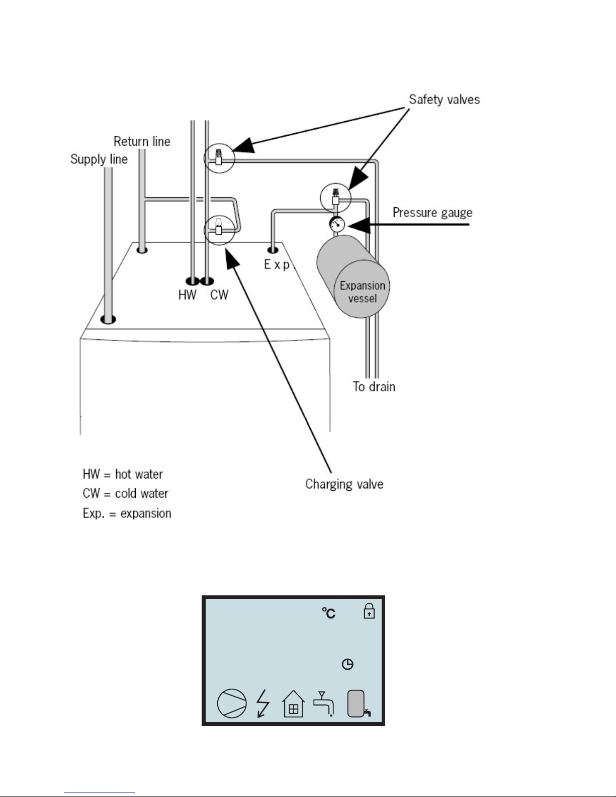
GROUND SOURCE HEAT PUMP
- ALL IN ONE-
MODEL:
BWA-SS-6 BWA-SS-8
(230V/50HZ)
BWA-SS-8 BWA-SS-10
BWA-SS-12 BWA-SS-16
(3x400V/3/50HZ)
-Please read this operating manual before using the Heap Pump-
USER MANUAL
TYDP
Page 2

List of contents
1
Important Information……………………………………………………..3
1.1
Safety Instructions
………………………………………………………………..3
1.1.1
Installation and Maintenance
……………………………………………………...3
1.1.2
Modification of
System Components
……………………………………………….3
1.1.3
Safety V
alve
……………………………………………………………………...3
1.2
Protective Measur
es
…………………………………………………………..…..3
1.2.1
Pr
eventing Corr
osion
..…………………………………………………………...3
2
Unit Description
……………………………………………………….…….3
2.1 Heat Pump Principle
………………………………………………………..….4
2.2
Auxiliary
Heater –
Electric Heating Element
…………………………….....….5
2.3
Water
Heater
……………………………………….…………………….....….5
2.4 Contr
ol Panel
………………………………………………………….….....….6
2.4.1 Functions
………………………………………………………….………
.....….7
3
Operating Instructions
……………………………………….……….....…..7
3.1
General Information
……………………………………….……….....………..7
3.1.1
Menu Navigation
……………………………………….………....................…..7
3.1.1.1 Display of
curr
ent operating mode
…………………………………….....…..7
3.1.1.2 Symbols
..…………………………………………………………...….....…..8
3.1.2
Menus
…………………………………………………………
…...….....…...9
3.1.2.1 Main Menu INFORMA
TION
……………………………………………...….......9
3.1.2.2 Sub-Menu OPERA
TION
……………………………………………...….....…..10
3.1.2.3 Sub-Menu HEAT
CUR
VE
..……………………………………………...….....….11
3.1.2.4 Sub-Menu TEMPERA
TURE
………………………………………………...….......12
3.1.2.6 Sub-Menu OPERA
TING TIME
…………………………………..……...….....….15
3.1.2.7 Sub-Menu RESET
……………………………......…………………..….....….15
3.1.2.8 Sub-Menu MAN TEST
………………………………………..………...….........15
3.2
Adjustments to be
made regularly
……………………………………...........18
3.2.1
Heat Generation – General
………………………………..………...…..............18
3.2.2
Adjustment of the CURVE
value
………………………………..………...…........18
3.2.3
Adjustment of ROOM value
………………………………..……… ...................19
3.2.4
Adjustment of
Par
t of the Heat Cur
ve
………………………………….... ..........21
3.2.5
Adjustment of the
MIN
and MAX value
………………………………… .............22
3.2.6
Adjustment of the HEAT
STOP value
………………………………….... ............23
3.2.7
Graph of r
ecent changes in TEMPERA
TURE
…………………………….....…........23
3.3
Maximum Return Line T
emperatur
e
…………………………….....…
.........24
3.4
W
arm W
ater Pr
oduction
………………………………..………….....…........24
3.5
Regular Checks
………………………………………………
…......…........24
3.5.1
CheckofOperating
Mode
……………………………
........................…........24
3.5.3
Checking the W
ater Level of the Heating System
…………………………...….....25
3.5.4
Checking the Safety V
alve
……………………………
.....………………….....25
3.5.5
In
the Event of Leakage
……………………………… ......………………….....25
4
Trouble shooting
…………………………….....…………… …...............26
4.1
Alarm Messages
…………………………….....………………….......
5
T
erminology
and Abbr
eviations
…………………………….......….......27
6
Default Settings
………………………….....…………………..................28
7
Refer
ences………………………….....……… …………....... .................28
3.1.2.5 Sub-Menu INTEGRAL
………………………………………………......….......12
3.1.2.9
Sub-Menu
SETTING
………………………………………..………...….........16
3.1.2.10
Sub-Menu
LANGUAGE
………………………………………..………...….......18
.........26
3.5.2
Checking the Brine Level of the Brine System
…………....………………...….....24
Page 3

BWA-SS series
is a
climate system
for heating houses and apartment buildings as well as industrial properties.
Ground, rock or lakes can be used as the heat exchange source.
BWA-SS seriesis a
complete heating installation
for
heating and hot water.
3
It is fitted with new design on the market
to be
developed specifically
for
heat pumps. A new evaporator enables a
new and impr
oved
cir
culation system
for
the r
efrigerant. The heat pump has an integrated 150 or 200 litre
water tank and
1
Important Information
* If the installation will be shut down during the winter months, the heating system
should be emptied of water
to
avoid any damage due
to freezing.
(Call your Installation Contractor
for
help, see ”Refer
ences” on page 30).
*
The installation is practically maintenance fr
ee, but some monitoring will be required (see ”Operating
Instructions” on page 7).
*
Before
making any adjustments of system parameters,
first
find out, what the
consequences are in
each case.
*
For all service work, please call your installation contractor.
1.1 Safety Instructions
1.1.1
Installation and Maintenance
Installation and commissioning as well as r
epairs and maintenance must be
carried out by a qualified installation
contractor (see ”Refer
ences” on page 30).
Any changes in the electrical installation must be under
taken by a qualified
electrician (see ”Refer
ences”on page
30).
Service work on the r
efrigerant
cir
cuit must be carried out by a qualified r
efrige- ration technician (see ”Refer
ences”
on page 30).
Danger to Life!
1.1.2
Modification of System Components
The below components can only be modified by a qualified installation
contractor:
*
Heat Pump Unit
*
Refrigerant,
warm water and power lines
*
Safety V
alve
No structural changes may be made
to
the installation that might af
fect the operational r
eliability of the heat
pump.
1.1.3
Safety V
alve
The following safety instruction s must be observed in r
egard of the safety
valve of the heating
cir
cuit and the
overflow pipe:
*
Never close the connection between safety valve and overflow pipe.
*
When heated, water tends
to
expand which causes some water
to be
let out thr
ough the overflow pipe. This water
may be hot! The overflow pipe should
ther
efore
discharge
into a floor drain placed so that nobody can get hurt.
1.2 Pr
otective Measur
es
1.2.1
Pr
eventing Corr
osion
T
o eliminate any risks of
corr
osion, the use of all kinds of aeor
osol should be
avoided in the pr
oximity of the heat
pump. In particular,
avoid the following:
Solvents
*
Deter
gents containing chlorine
*
Paint
*
Glue
2
Unit Description
In order to get the best results from the climate system BWA-SS series you should read through the
section For the System manager in these Installation and Maintenance instructions.
*
Page 4

4
BWA-SS series
consists of five main components:
and
Brine sytem)
2.1 Heat Pump Principle
A heat pump can exploit the energy
contained in natural heat sour
ces. Or, to
put it
dif
fer
ently,
the heat
pump ”collects” heat energy from the heat sour
ce.
This makes the heat pump a very environmentally friendly and
economically sound
alternative
for
space heating.
a.
A
hose filled with liquid (Brine system) is immersed into a lake, dug into the gr
ound or sunk into the r
ock. The
Brine sytem absorbs the heat
energy of
the heat source so that the temperature of
the water
cir
culating in the
hose is raised a few degr
ees.
b
The Brine system is
cir
culated
to
the heat pump’s
evaporator.
Here the heat
energy of
the Brine system causes the
r
efrigerant,
cir
culating thr
ough the evapo
rator, to
boil and turn into a gas – it evaporates.
c
The r
efrigerant, having absorbed heat energy, is
cir
culated
to
the compr
essor
where pressure
and temperature
are
raised.
d
The r
efrigerant continues
to
the condenser.
When condensing, it r
eleases heat
energy to
the heat carrier,
cir
culating thr
ough the condenser.
The
temperature of the r
efrigerant sinks, and it r
eturns
to
its liquid state.
e
The heat energy released is carried by the heating
cir
cuit
to
water heater and
radiator or floor heating systems.
f
At
last the r
efrigerant is
led thr
ough the expansion valve, where
its pr
essure is reduced, and then con
tinues
to
the
evaporator.
The pr
ocess is r
estar
ted.
an immer
sion heater.
The Tap Water Stratification system impr
oves the ef
ficiency of heat transfer by keeping the water in
distinct thermal layers in the water tank.
The unit is
fitted with a r
egulating computer,
which is contr
olled over a graphic display unit.
Heat is distributed thr
oughout the house over a hydr
onic heating system referred to as
low temperature
system with a maximal water temperature to
radiators ( Feed line temperature) of 65°C. Most of the heating
demand is
taken care of by
the heat pump (compressor unit), the auxiliary heater being
star
ted only when
demands exceed available heat pump capacity.
a. Heat Pump Unit
Rotory or Scr
oll-compr
essor
Stainless steel heat exchangers
Cir
culation pumps
for
heating systems
V
alves and safety equipment
for refrigerant system, complete with
necessary electric components
b. W
ater
Heater
150 or 200
litr
e
Lined
with copper sheet against
corr
osion or made of stainless steel
Maintenance free as no
anode is used
c. Reversing V
alve
Opening or closing the connection
to
water heater accor
ding
to
operating mode: heating or warm water pr
oduction
d. Auxiliary
Heater
3 / 6 / 9 kW electric heating element
Three-step capacity contr
ol
Fitted on supply line
Delivers back-up heat in case of gr
eat heat demand that exceeds heat
pump capacity
Star
ts
automatically, provided operating mode “AUTO” has been selected
e. Regulating Equipment
The r
egulating system contr
ols heat pump components (compressor, cir
culation
pumps, auxiliary heater and
r
eversing valve). Based on data r
eceived fr
om sensors, it star
ts or
stops heat pump operation and determines
whether heating or warm water shall be pr
oduced. The system consists of:
Control computer with graphic display unit
T
emperature
sensors (outside air
,room, feed line, r
eturn line
Page 5
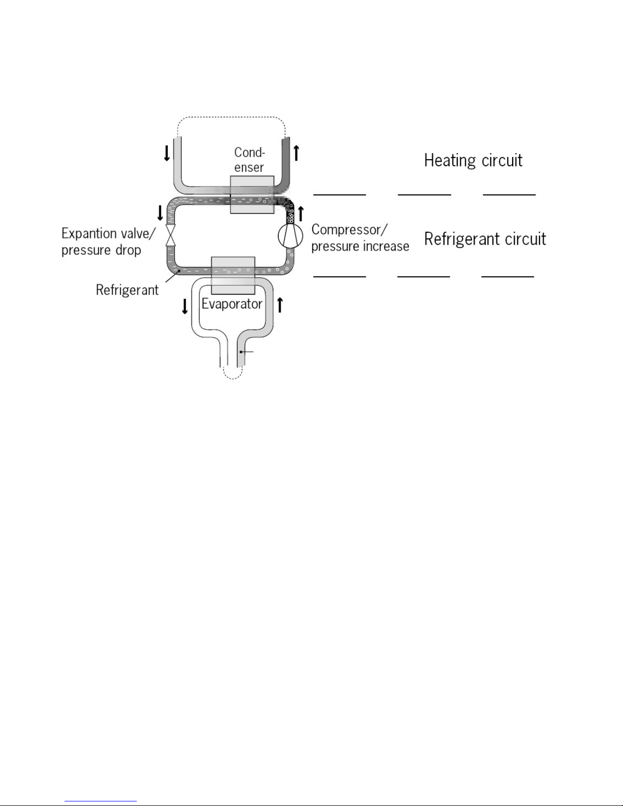
The heat pump has three
separate liquid
cir
cuits
Brine sytem
cir
cuit
– a
water-based mixture
(brine) transporting energy from
heat source
to
heat pump.
Refrigerant
cir
cuit
–
cir
culating inside the heat pump. Thr
ough evaporation,
compr
ession and condensation it
absorbs energy from the Brine sytem and r
ele
ases it
to
the heat carrier.
The r
efrigerant is chlorine-fr
ee.
Heating
cir
cuit
–
water transporting heat energy to
the heating system (radia
tors/floor coils) and the water
heater.
5
Brine system circuit
Brine system
2.3 W
ater
Heater
BWA-SS series comes with a built-in water heater holding 150 or 200
litr
es. The temperature of
the water sent
to
the water heater is contr
olled by the r
egulating pr
essure switch and cannot be adjusted. Warm water pr
oduction is
stopped when the r
egulating pr
essure
switch r
eaches its
operating pr
essure,
which
corr
esponds
to
about 50-55°C warm
water temperature.
At r
egular intervals the water in the water heater will be heated
to as
much as 65°C
as a pr
eventive
measure
against bacteria. The pr
eset interval is 14 days. For more information, please r
efer
to ”Warm W
ater Pr
oduction”
on page 24.
.
The heat
pump has three separate liquid circuits
2.2 Auxiliary
Heater –
Electric Heating Element
The auxiliary heater – an electric heating element fitted on the supply line – has
three
capacity steps:
Step 1 = 3 kW
Step 2 = 6 kW
Step 3 = 9 kW
Page 6
BWA-SS
6
2.4 Control
Panel
The control
panel of
BWA-SS series
features a
graphic display,
five contr
ol
buttons
.
Beside the control
panel you will find the User’s
Manual, a short
description of how
to
incr
ease and r
educe r
oom
temperature, and a label with name and phone
number of
dealer
.
Graphic display
ROOM 20
OPER. WARMWATER
MONDAY
11:30
1
Page 7
7
2.4.1 Functions
3 Operating Instructions
3.1 General Information
3.1.1
Menu Navigation
3.1.1.1 Display of
curr
ent operating mode
Control Buttons
˄
influence key˅
The control computer is operated with the help of a user friendly menu system that is displayed on the control
panel. There is a main menu and several sub-menus accessible from the main menu. The menus are
described in detail further down.
To be able to select the desired menu and increase or reduce preset values, you will use the five buttons.
• One button pointing upwards marked with a up arrow
• One button pointing downwards marked with a down arrow
• One button pointing to the right marked with a right arrow
• One button pointing to the left marked with a left arrow
• One button pointing to the ON/OFF
The right-hand button on the control panel is used to open the desired menu.
The left-hand button is used to return to the previous menu.
The up and down buttons are used to navigate between the parameters of a menu.
A cursor (arrow) on the left-hand side of the display indicates which menu can be opened.
The up and down buttons are also used if you wish to increase or reduce a preset value.
When display at the interface, press button Right for 5 seconds for locking the display (will show a symbol
of lock.) All buttons are not available after lock is active, until press button Right for 5 seconds to open the lock˗
if the lock is active and then power supply cut off, the lock will be open after power supply resume.
During normal operation, the following information will be displayed:
• Desired (preset) room temperature
• Date / time / timer
heat pump or auxiliary heater or both (see ”Symbols”).
• Which operating mode has been selected.
• Whether there is a heating demand or not. If there is, there will
also be symbols telling which heat source is working,
ROOM 2 0
OPER. WARMWATE R
MONDAY
11:3 0
1
ROOM 20
OPER. WARMWATER
MONDAY
11:30
1
Page 8
8
Symbols
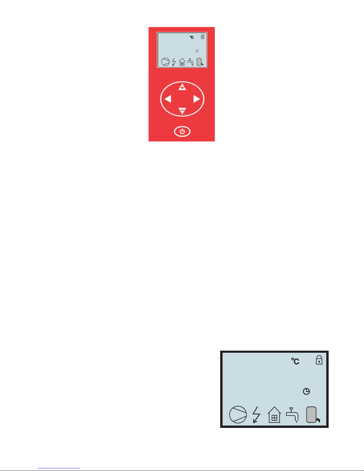
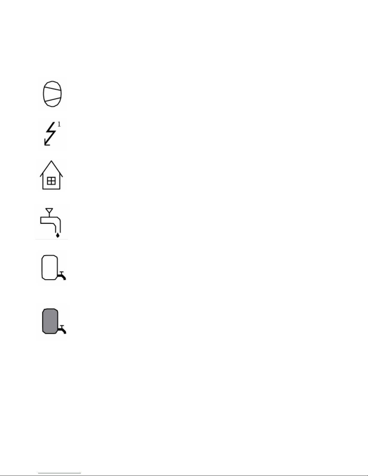
For you to know at a glance the actual operating mode of the heat pump, each of the following symbols
will be shown in the lower part of the display depending on which part of the unit is working:
1. The heat pump is running.
2. The auxiliary heater is activated.
3. There is a room heating demand.
4. Warm water is being produced.
5. Indicates the status of warm water production. If the symbol is empty, warm water temperature is
under the setting temperature. It does not mean that there is no water in the water tank.
The tank is always full.
6. If the symbol is full, warm water temperature reached to the setting temperature.
Page 9
9
3.1.2 Menus
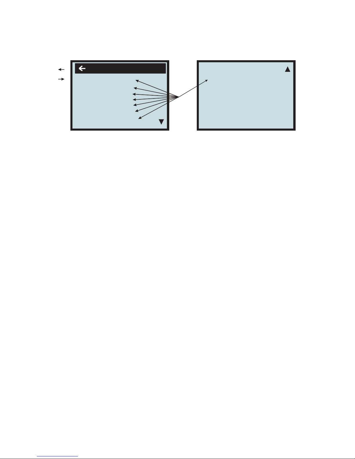
3.1.2.1 Main Menu INFORMA
TION
To
open the main menu INFORMA
TION, pr
ess the right- or left-hand button once.
T
o select the desired
sub-menu, use the up or down button. Open the menu by pr
essing the right-hand button once.
To return
to
the main menu, pr
ess the left-hand
button once.
SETTING
INFORMATION
OPERATION
HEATCURVE
TEMPERATURE
INTEGRAL
OPER.TIME
RESET
MAN TEST
LANGUAGE
Sub
menus
Return
Open
next
menu
OPERATION
Running mode: Room heating 1, Room heating 2,Water tank heating.
HEATCRVE
The setting of this submenu will affect the room temperature; CURVE is program that adjusts feed water
temperature according outdoor ambient temperature, factory setting is ambient temperature 0ഒ as feed water
temperature 40ć, that is CURVE =40; the value of CURVE is adjustable from 22ć to 56ć. How to change
the slope—two points decide one beeline, point one is (0,40), the other point could be (18,24), the point
(18,24) is not changing when changing the slope, because factory setting is that heat pump stops when
outdoor ambient temperature is 18ć, so the feed water temperature should be 24ć.
TEMPERATURE
Temperature items setting.
INTEGRAL
Integral is a program to set the startup time and distance between compressor and electrical heater, to set
stop conditions of compressor and electrical heater. This program is depends on the "feed water temperature
degeneratiaon" and Time.
SETTING
OPER.TIME
To calculate how much time have been running by compressor, electrical heater.
RESET
Return to factory settings: press button Right to go back all factory settings.
MAN TEST
Engineer testing
To set Daytime,Time, electrical heater timing, water tank heating timing, whole unit timing, Emergency mode 1,
Emergency mode 2, auxiliary electrical heater.
Page 10
10
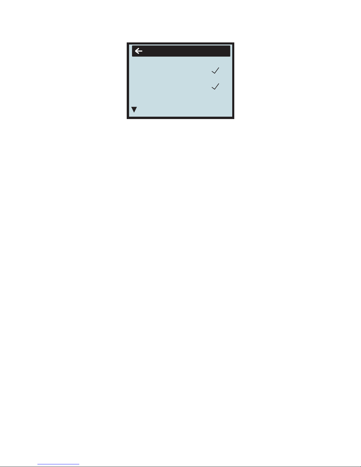
3.1.2.2 Sub-Menu OPERA
TION
ROOMHEAT1
᧶
ROOMHEAT2
᧶
WARMWATER+ROOMHEAT1᧤ROOMHEAT2
᧥᧶
HEATPUMP᧤ON or OFF
᧥
ON᧶select ON, compressor is running normally.
OFF᧶select OFF, only switch off compressor᧨the others are running normally.
ADD.HEAT
᧤
ON or OFF
᧥
ON᧶select ON, electrical heater is running normally.
OFF᧶select OFF, only switch off electrical heater᧨the others are running normally.
If you wish to change operating mode:
a. Open the main menu INFORMATION by pressing the right-hand button once. You will find the cursor at
thesub-menunamedOPERATION.
b. Open the OPERATION menu by pressing the right-hand button once. You will find the cursor at the
previously selected operating mode.
c. Select the desired mode by pressing either the ”up” or ”down” button.
Return to the main menu by pressing the left-hand button twice.
After select mode ROOMHEAT 1, the heat curve is that feed water temperature determined by outdoor
ambient temperature. At the time, ROOMHEAT2 be of no effect.
After select ROOMHEAT 2, feed water temperature is adjustable from 10 to 65ć, factory setting is 45ć. At
the time, the system is controlled by time and flow temperature, ROOMHEAT 1 is of no effect (not affected by
ambient temperature)
Auto mode: select (¥) water tank heating and room heating at the same time, enter Auto mode. After enter
this mode, water tank heating has the priority (compressor restart when in water tank heating must follow
program ‘CMPDI TEMP’). When water tank get to setting temperature, three -way valve will change its
direction to room heating automatically. If the water tank temperature decrease, three-way valve’s direction will
go back to water tank heating.
OPERATION
ROOMHEAT 1
HEATPUMP
ADD.HEAT
ON
ON
WARMWATER
ROOMHEAT 2
Page 11
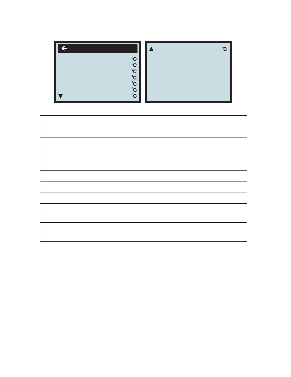
3.1.2.3 Sub-Menu HEA
T CUR
VE
This menu is used for making adjustments
that af
fect the r
oom temperature.
For more
information, please r
efer
to ”Adjustments to be made r
egularly” on
page 20.
T
able 1: Menu– HEAT
CURVE
Menu
T
ext Description Adjustable b
y
CURVE
The value
enter
ed shows
the
temperatureof
the
water
tobedistributedtothe
radiators
(feed
water
temperature)when
the outside air
temperatureis0°C.
used(see ”Adjustment
of
CURVE
value” on
p18.
)
MIN
Adjustmentofvalue
for
lowest
feed
water
temperatur
e
allowed.
used(see ”Adjustment
of
MIN & MAX
value” on
p22.
)
MAX
Adjustmentofvalue
for
highest
feed
water
temperatureallowed.
used(see ”Adjustment
of
MIN & MAX
value” on
p22.
)
CURVE
5
Adjustmentofr
oom temperaturewhen
the outside air
temperatureis+5°C.
used(see ”Adjustment
ofCURVE
value” on
p18.
)
CURVE
0
Adjustmentofr
oom temperaturewhen
the outside air
temperatureis0°C.
used(see ”Adjustment
ofCURVE
value” on
p18.
)
CURVE–5
Adjustmentofr
oom temperaturewhen
the outside air
temperatureis-5°C.
used(see ”Adjustment
ofCURVE
.
)
HIGH T STOP
When outdoor ambient temperature is higher than
this setting, the hot water to room will
be stopped.
this setting is adjustable
from 0 to 50ć,factory
setting is 50ć.
LOW T STOP
When outdoor ambient temperature is lower than
this setting, the hot water to room will be stopped.
this setting is adjustable
from 0 to -50 ć,factory
setting is -50ć.
value” on P18
LOW T° STOP
-50
HEATCURVE
CURVE
MIN
MAX
CURVE 5
CURVE 0
CURVE
- 5
40
22
70
0
0
0
HIGH T° STOP
50
11
Page 12
12
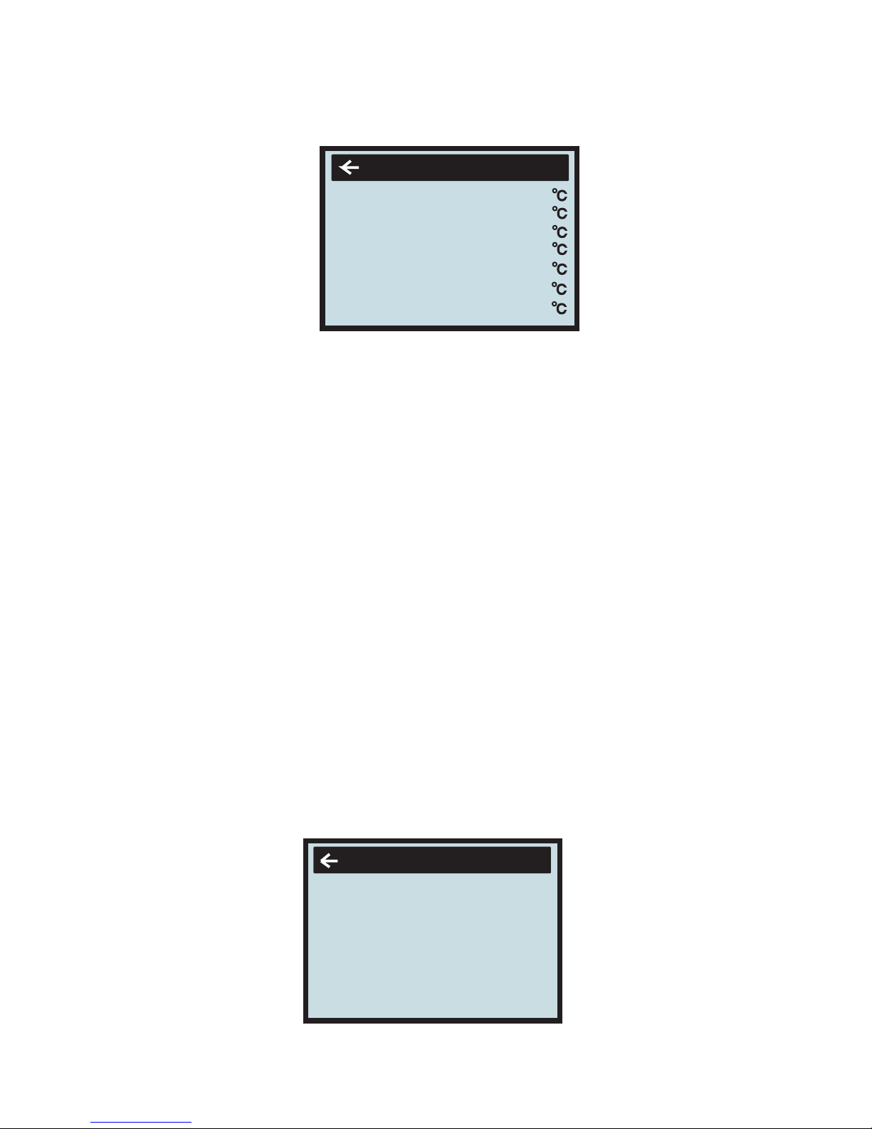
3.1.2.4 Sub-Menu TEMPERA
TURE
This menu shows the dif
fer
ent temperatur
es
of the heating system. All temperature changes r
egistered
over
the
last 60 minutes are stored in
the control
system and can be
viewed in the shape of graphs.
WARMWT ˖ water tank temperature, the first value is water tank real temperature, the second value in
‘ ( )’ is water tank setting temperature; the setting temperature is adjustable from 20 ć to 62ć,factory
setting is 45ć.
ROOM˖ Display room air temperature.
RETURN
˖ Display return water temperature.
FEED˖
1.the first value is real feed water temperature, the second value in ‘( )’ is feed water setting
temperature in ROOMHEAT 1 mode, it is adjusted by slope of Curve according to outdoor ambient
temperature. Factory setting is that feed water temperature is 40ć when outdoor ambient temperature is
0ć, that is to say Curve is 40, the value of Curve is adjust from 22ć to 56ć. This setting is only
available for Room heating, not for water tank heating.
2. under ROOMHEAT 2 mode, FEED setting can be adjust directly from 20 to 65ć,factorysetting
is 45ć; this setting is only available for room heating, not for water tank heating.
OUT
˖Display outdoor ambient temperature.
When at item WARMWT or RETURN or FEED, or BRINE IN or BRINE OUT, press button Right
BRINE IN:
Display the temperature of Brine system when entering the heat pump.
BRINE OUT:
Display the temperature of Brine system when leaving the heat pump.
5 seconds willdisplay the information as follow kind of chart, to check how the temperature is going
in one hour.
3.1.2.5 Sub-Menu INTEGRAL
INTEGRAL
00
OFF
CMP.A
ADD 1
- 60 ( 00)
( - 60)
- 500
00
ADD 2
( - 500)
- 550
ADD 3
( - 550) - 600
TEMPERATURE
OUT
ROOM
FEED.
RETURN
WARMWT
BR . IN
25
28
45
30(65)
30(50)
BR . OUT
15
18
Page 13
13
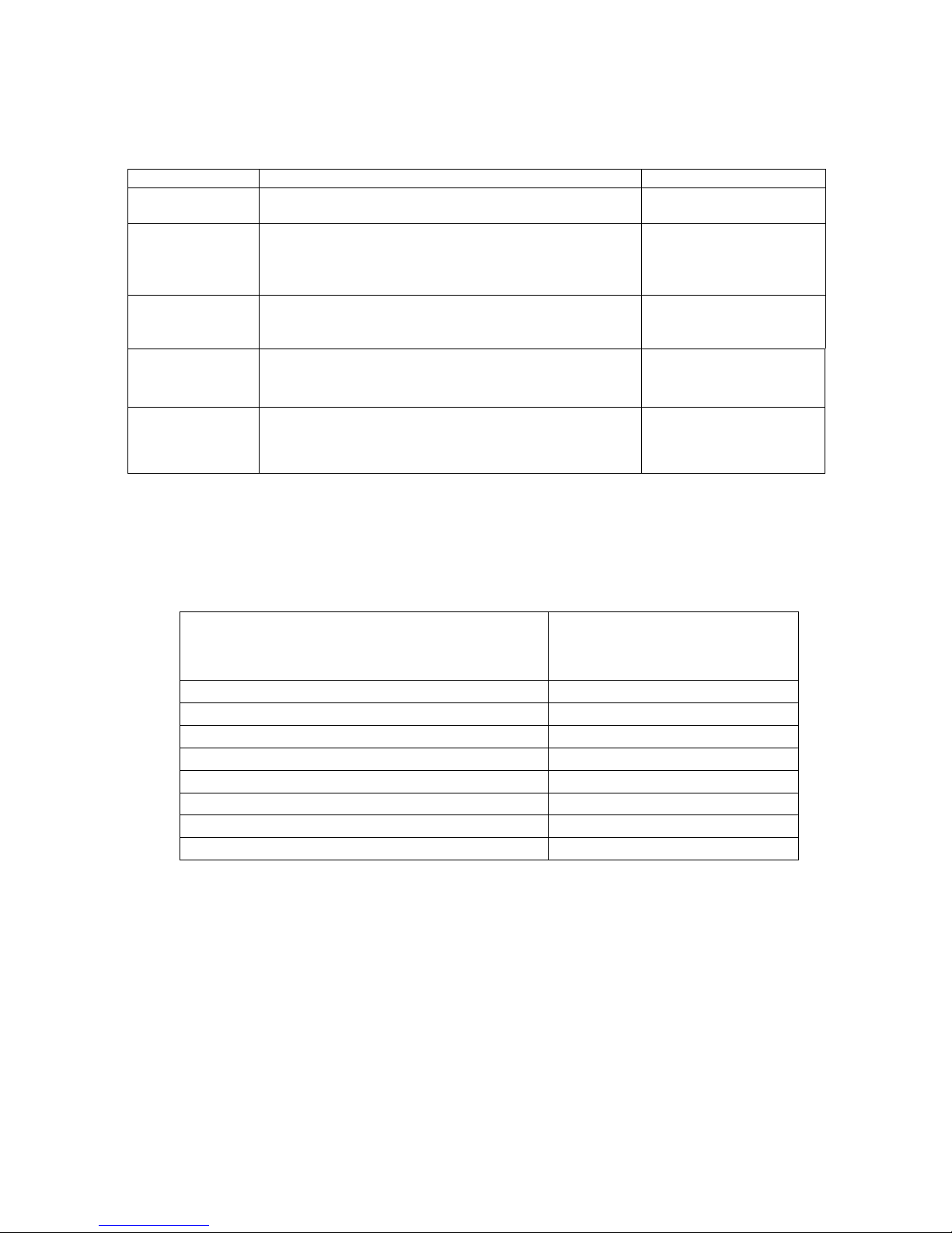
Integral (DM) is a program to set the startup time and distance between compressor and electrical
heater according to heat demand and heat output, to set stop conditions of compressor and electrical
heater. This program is depends on the "feed water temperature degeneratiaon" and Time. To enter this
menu operator can change the factory setting:
Menu Text Description Adjustable by
OFF When the value (testing) reaches the value setting by
use
r
,thesystem will be closed.
USER
CMP.A
When the value (testing) reaches the value setting by
user, the compressor will be start-up. And the value
(testing) under the value (setting), the compressor will
be closed.
USER
ADD1 When the value (testing) reaches the value setting by
user, the ADD 1 will be start-up. And the value (testing)
under the value (setting), the ADD1 will be closed.
USER
ADD2 When the value (testing) reaches the value setting by
USER
ADD3 When the value (testing) reaches the value setting by
USER
user, the ADD2will be start-up. And the value (testing)
under the value (setting), the ADD2 will be closed.
user, the ADD 3 will be start-up. And the value (testing)
under the value (setting), the ADD3 will be closed.
Instruction of Integral (DM)
Degree Minute = The corresponding value of temperature difference between the Feed water
and the Desired water X Running time ( through integral to change; every minute for a cumulative)
For example:
(Under desired temperature)
Feed water temperature decrease 1ć (under desired temperature) in 1 minutes,
Degree Minute=-10 X 1= -10;
Feed water temperature continue decrease 2ć(under desired temperature) in another 1 minutes,
Degree Minute=-10 X 1 + (-10) = -20;
Feed water temperature continue decrease 3ć(under desired temperature) in another 1 minutes,
Degree Minute=-10 X 1 + (-20) = -30;
Feed water temperature continue decrease 4ć(under desired temperature) in another 1 minutes,
Degree Minute=-10 X 1 + (-30) = -40;
……………………
Temperature difference between the feed water
and the desired water ( ć )
The corresponding value
-31 ~ -40 -40
-21 ~ -30 -30
-11 ~ -20 -20
-1 ~ -10 -10
1~10 10
11 ~ 20 20
21 ~ 30 30
31 ~ 40 40
Page 14
14
Before the Degree Minute reach - 60 (adjustable) ,the compressor is off, but when the Degree Minute
reach - 60 (adjustable) ,the compressor automatic start, and the flow temperature will begin increase.
(Higher than desired temperature) when the actual water supply temperature reach / higher than the
desired temperature, the DM will be changed.
For example : the DM was cumulated to -160 in this time.
1 minutes later when the Feed water temperature higher than desired temperature for 1ć.
10X1=10 , Degree Minute= -150;
Another 1 minutes later when the Feed water temperature higher than desired temperature for
2ć. 10X1=10, Degree Minute= -140;
Another 1 minutes later when the Feed water temperature higher than desired temperature for
3ć. 10X1=10, Degree Minute= -130;
Another 1 minutes later when the Feed water temperature higher than desired temperature for
4ć. 10X1=10, Degree Minute= -120;
……………………
Compressor off when Degree Minute reach 0 (adjustable) .
The relationship between compressor (on and off) and DM,the relationship between heater(on and off)
and DM.
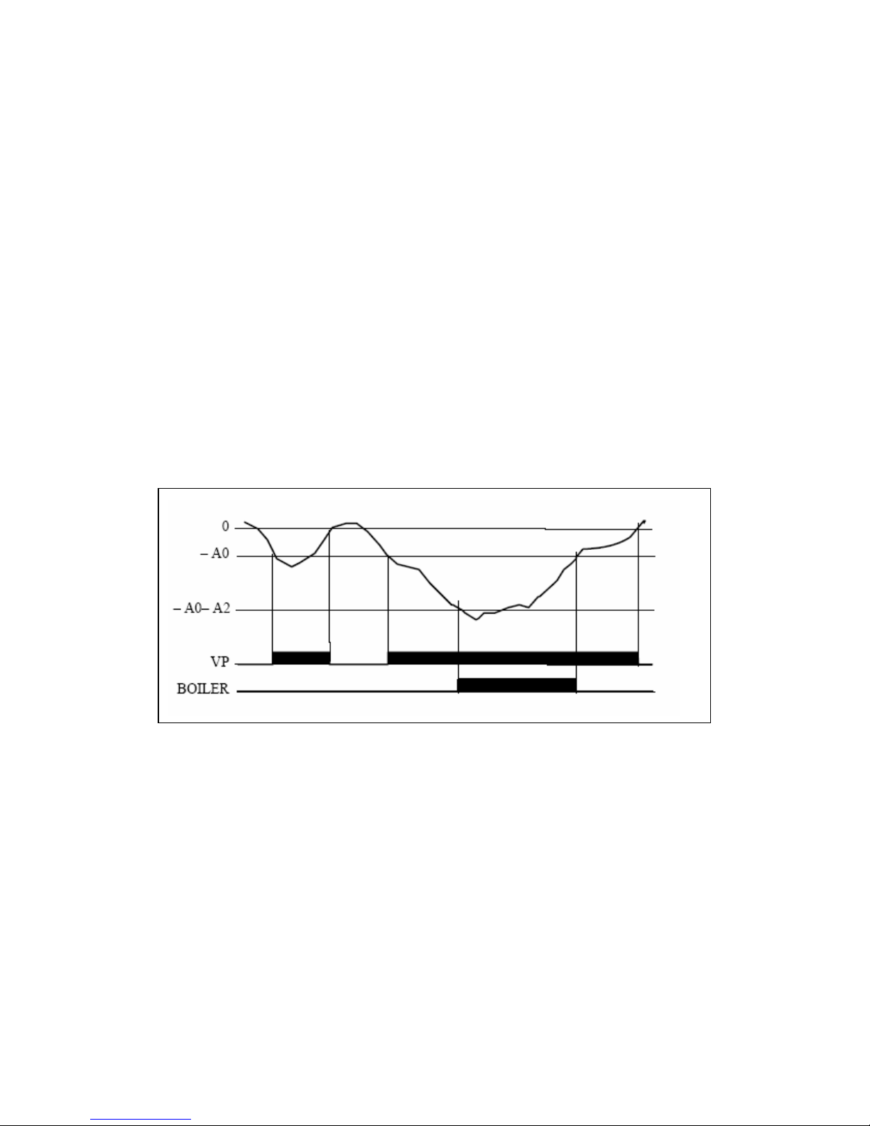
The above chart is describing that running of compressor and electrical heater depend on Integral
Compressor ‘s Degree Minute are :-60 (on) and 0(off),A0=-60 (on)
Heater 1’s Degree Minute are : ‘-500’(on) and ‘-60’(off), A0+A2=-60-440=-500 (on)
Heater 2’s Degree Minute are : ‘-500’(on) and ‘-500’(off)
Heater 3’s Degree Minute are : ‘-600’(on) and ‘-550’(off)
Page 15
15
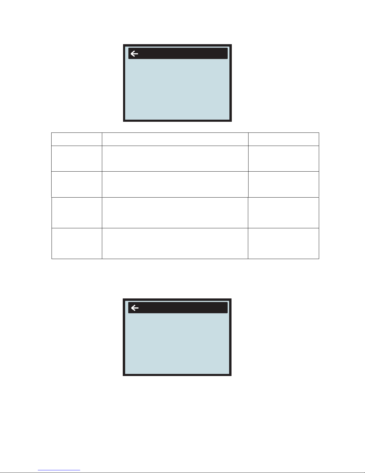
3.1.2.6 Sub-Menu OPERA
TING TIME
3.1.2.8 Sub-Menu MAN TEST
3.1.2.7
Sub-Menu RESET
Reset to factory setting value. Press the right button for 5 seconds.
The Sub-Menu MAN TEST contains ADD1 / ADD2 / ADD3 / HEAT PUMP / 3 WAY /
BRINE PUMP / WARM PUMP ; You can choose ON / OFF to control the each part for testing.
How to enter the Sub-Menu MAN TEST:
You need to choose the " MAN TEST" on the main menu ( INFORMATION)
And press the right button for 3 seconds .
MenuText Description Adjustable b
y
HEATPUMP Total operating hours of heat pump since installation.
Operatin
g
time will not be reset to zero.
(3kW) since installation. Operating time will
ADD1 Total operating hours of auxiliary heater
ADD2
ADD3
will not be reset to ze
r
o.
(6kW) since installation. Operating time will
Total operating hours of auxiliary heater
will not be reset to ze
r
o.
(9kW) since installation. Operating time will
Total operating hours of auxiliary heater
will not be reset to ze
r
o.
can not
can not
can not
can not
OPERATION TIME
HEATPUMP
ADD 1
0
H
0
H
ADD 2
0
H
ADD 3
0
H
ADD 1
3 WAY
WARM PUM P
MAN TEST
OFF
OFF
OFF
OFF
ADD 2
OFF
ADD 3
OFF
HEATPUMP
OFF
Notice: when installer to test the components function in submenu ‘MAN TEST’, it recommend that
start the water pump before start the compressor and electrical heater.
BRINE PUMP
Page 16
16
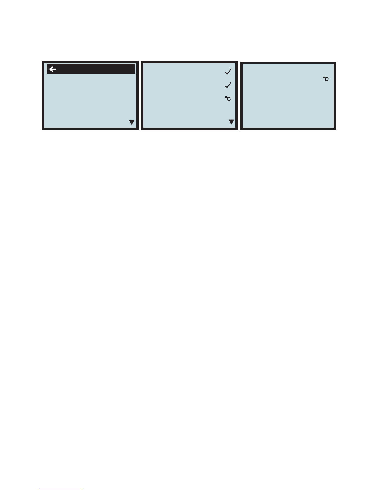
3.1.2.10 Sub-Menu SETTING
How to enter the Sub-Menu SETTING:
Press the right button.Then " SETTING" menu can be seen.
You need to choose the " SETTING" on the main menu ( INFORMATION).
EMERGENCY 1
EMERGENCY 2
OFF
ON -25
SETTING
TIMER 1 ON
TIME
X
11:30
DATE TIME MON
TIMER 1 OFF
X
TIMER 2 ON
X
TIMER 2 OFF
X
ADD.HEAT TIMER
(ON)21:00-08:00(OFF)
WARMWT TIMER
(ON)18:00-22:00(OFF)
CMPDIF TEMP
5
DATE TIME
To display or adjust day of week.
TIME
To display time, or adjust time.
Double timer function:
TIMER1 ON ˖
¥
9˖00 TIMER1 OFF ¥ 1 2˖00
TIMER2ON
˖
¥
14˖00 TIMER2 OFF ¥ 18˖00
TIME ON
When choose mark “¥”, the Auto start function is active, choose “×”for cancel this function. If this function
is active, every day during the timing, the heat pump will work normally.
TIME OFF
When choose mark “¥”, the Auto stop function is active, choose “×”for cancel this function. If this function
is active, every day during the timing, the heat pump will stop normally.
ADD.HEAT TIMER ¥
( ON) 21:00-----9:00 (OFF)
When choose mark “¥”, the Auto start function of electrical heater is active, choose “×”for cancel this
function. If this function is active, every day electrical heater will start and stop automatically according to the
setting.
WARMWATER TIMER ¥
( ON) 21:00-----9:00 (OFF)
When choose mark “¥”, the Auto start function of water tank heating is active, choose “×”for cancel this
function. If this function is active, every day water tank heating will start and stop automatically according to the
time setting.
CMPDIF TEMP:
compressor restart determined by water temperature degeneratiaon of water tank. This
ć, and factory setting is 5ć.
setting is only
for water tank heating, it is adjustable from 3 to 15
ADD DELAY
30 M
ADD START
50
STERILAZE
HDO
OFF
Emergency mode 1˄emergency 1˅:˄ON or OFF˅ˈfactory setting is OFF(after select emergency mode,
the unit will continuously execute the same objective (room heating only, water tank heating only, or auto)
When select ON, compressor will be switch off, only electrical heater, water pump or other temperature
protection are available. When in water tank heating, the electrical heater will instead of compressor; when in
room heating mode, the electrical heater will runs depends on Integral; when in room heating mode 1, the
electrical heater will runs depends on Integral; when in room heating mode 2, the electrical heater
automatically starts, unless operator off the electrical heater.
EMERGENCY1 (ON or OFF)
When heat pump is ON, water tank timer function makes sure the water tank heating has priority.
If the heat pump is ON with mode WARMWATER only:
Then if set water tank timer to be: 6:00(ON) ---12:00(OFF), the water tank heating will be available only during
clock 6:00 –12:00.
If the heat pump is ON with mode Auto (WARMWATER+ROOMHEAT):
Then if set water tank timer to be: 6:00(ON) ---12:00(OFF), the water tank heating will be available only during
clock 6:00 –12:00, the rest time will turn to room heating.
Page 17

Emergency mode 2˄ emergency 2˅:˄ON or OFF˅ˈfactory setting is OFF: (after select emergency mode,
the unit will continuously execute the same objective (room heating only, water tank heating only, or auto)
When select this mode, compressor will stop determined by outdoor ambient temperature, the
temperature setting is from 0 to -50 degree adjustable, factory setting is -25 degree, only electrical heater,
water pump or other temperature protection are available. When in water tank heating, the electrical heater will
instead of compressor; when in room heating mode, the electrical heater will runs depends on Integral; when in
room heating mode 1, the electrical heater will runs depends on Integral; when in room heating mode 2, the
electrical heater automatically starts, unless operator off the electrical heater.
EMERGENCY2 (ON or OFF)
External signal controls heat pump start and stop: there two signal connections, when external relay
switch on them, the compressor, electrical hearer and motor will stop running. After switch off them, the
compressor, electrical heater, motor will restart and work as previous setting.
17
HDO ON (OFF)
1. Switch it on the input signal on the wire HDO would block the compressor, fan and additional heater˗
2. Switch it off, the input signal would block nothing.
ADD DELAY : ( 30 to 90 Min adjustable , factory setting is 30M )
when heating the water tank (after only runs compressor 10 minutes ), if two conditions are fulfilled,
the electrical heater 1 will start automatically: 1) the current water temperature more than
50 (this settingć
is adjustable from 45ć to 70ć); 2) the water temperature can not increase 1ć in a certain time (from 3 to 90
minutes adjustable, default is 30 minutes); after start electrical heater 1, if the water temperature can not
ćincrease 1 in a certain time, then electrical heater 2 will start automatically; after start electrical heater 2,
if the water temperature can not increase 1 ć in a certain time, the electrical heater 3 will start
automatically; then electrical heater work until water get the setting temperature.
ADD START : ( 45 to 70 degree adjustable , factory setting is 50 degree )
If the water tank’s temperature always less than 60ć (default) and last 360 hours(period), the heat
pump will start the sterilize function ( the electrical heater start as soon as water get to 50ć), until
water temperature get to 60ć(default) and last 10 minutes( default); or if 3 hours later the water
temperature still can not reach 60ć, the sterilize function will exit.
Sterilize water temperature:˄60ć--90ć adjustable˅default is 60ć
Sterilize duration :˄10—90minutes˅default is10 minutes
Sterilize period :˄7----99days˅default is 15 days
STERTLIZE
PERIOD
DURATION
15 D
120 M
WATER TEMP 60
STERILIZE:
Page 18
18
3.2 Adjustments to be
made regularly
3.2.1 Heat Generation - General
r
CURVE CC
40
18
C
0
5-5
24
32
40
48
56
64
18
Feed line
temperature
Heat curve
Relation of outside
air temperature to
Feed line temperature
Outside air temperature
Most settings will be made by the installation contractor in connection with installation. Adjustments to be
made regularly by the user are the following:
• Selection of operating mode
• Adjustment of desired room temperature by changing the ROOM value.
• Adjustment of heat curve
• Adjustment of maximum and minimum values for feed line temperature
The indoor temperature should be adjusted by changing the heat curve of the installation. The control
computer determines the correct temperature of the water to be distributed to the heating system based on
the heat curve. The heat curve will be adjusted in connection with installation. It must be adapted later on,
however, to obtain a pleasant indoor temperature under any weather condition. A correct heat curve
reduces maintenance and saves energy.
The heat curve determines the feed line temperature depending on the outside air temperature. The lower
the outside air temperature, the higher the feed line temperature. In other words, the temperature of the
water feed to the radiators will increase exponentially as the outside air temperature falls.
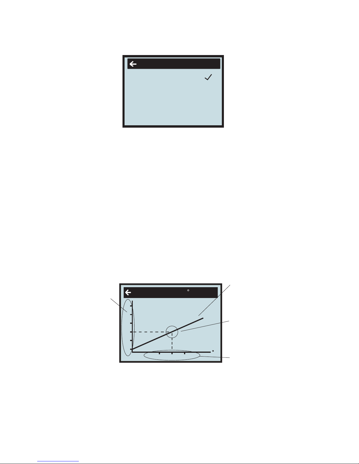
If you select CURVE in the sub-menu named HEAT CURVE, a diagram will be displayed. It represents the
relation of outside air temperature to feed line temperature. This relation is referred to as heat curve.
• Adjustment of the value
for
HIGH T STOP or LOW T STOP
is possible. (Please r
efer
to
”Adjustment of HIGH T STOP
or LOW T STOP value” on p. 25).
.
Adjustment of the CURVE value
The heat curve will be adjusted by the CURVE value. This value indicates the feed line temperature
to the radiators at 0°C outside temperature. At outside air temperatures lower than 0°C, the water sent to
the radiators will be warmer than 40°C.
At outside temperatures higher than 0°C, the water will be colder than 40°C. When you increase the
CURVE value, the heat curve will become steeper and when you reduce it, it will become flatter.
This is the most energy and cost efficient way to set the indoor temperature and should therefore be
used for long term temperature settings. If you wish to make a temporary change of temperature, you
can simply change the ROOM value (see ”Adjustment of the ROOM value” on page21).
3.2.2
3.1.2.11 Sub-Menu LANGUAGE
Language selection :
How to enter the Sub-Menu of LANGUAGE:
Press the right button.Then " LANGUAGE" menu can be seen.
You need to choose the "LANGUAGE" on the Main menu ( INFORMATION ).
Use Up and Down botton to select the language ,and press Right button to confirm.
LANGUANG
ENGLISH
DEUTSCH
Page 19
19
3.2.3 Adjustment of ROOM value
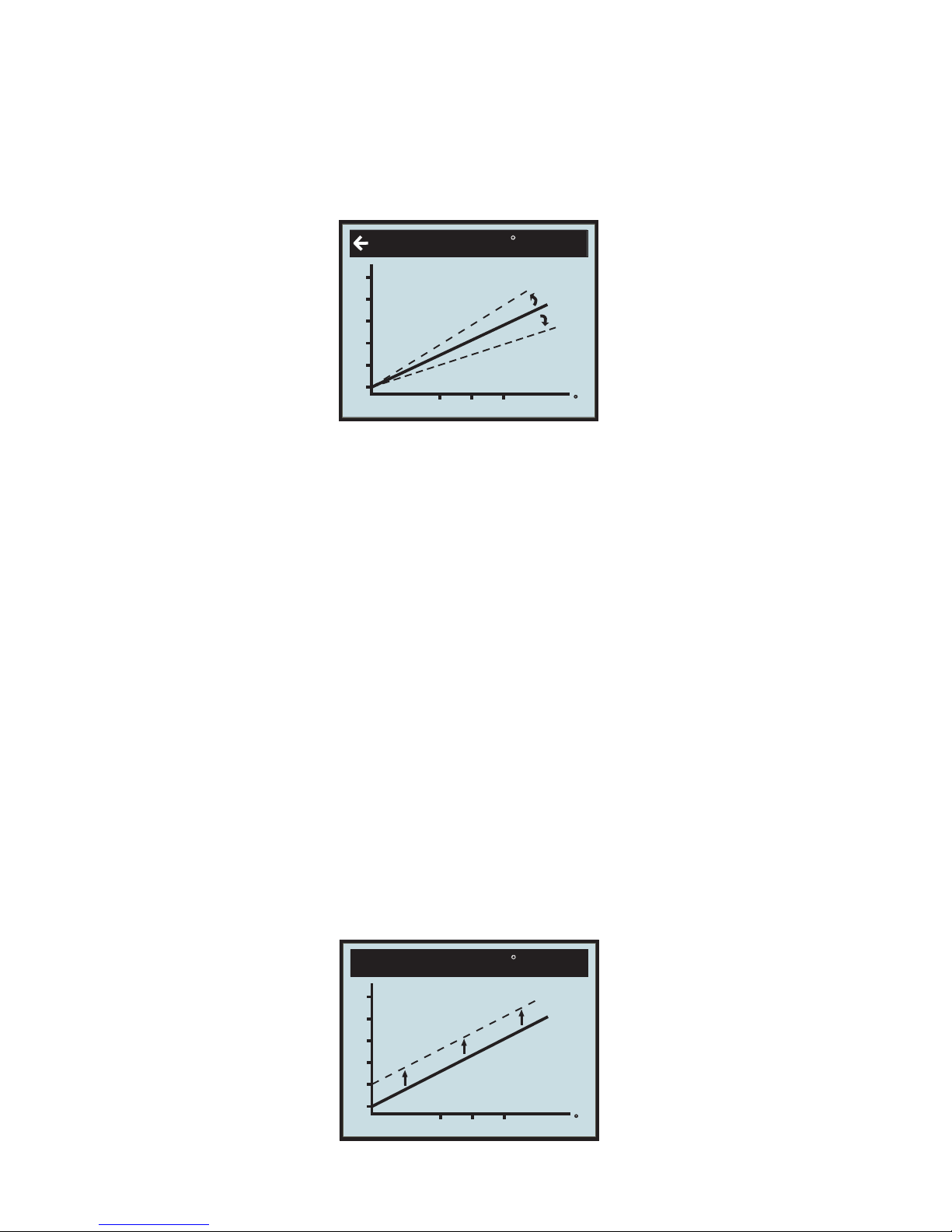
As mentioned above, you can also adjust heat curve and indoor temperature
by changing the ROOM value. If
you use ROOM value
to
adjust the heat curve, the
gradient does not change, i.e. it doesn’t become steeper or
flatter.
Instead, the
whole curve is moved by 1°C
for
every degree by
which the ROOM value is changed.
The r
elation feed line temperature to
outside air temperature
will not be affected. The feed line
temperature
will be incr
eased or r
educed by the same number of degr
ees all along the heat curve. See the
following diagram.
Adjustment of the ROOM value should only be used
for
temporary changes of the indoor temperature. For long
term settings, the CURVE value should be adjusted as this is the most energy
and cost efficient way
to
set the indoor
temperature.
For adjusting the heat curve, please r
efer
to
the chapter ”Adjustment of the CURVE value” on page 20.
Change of value
for
CURVE
CURVE C
C
40
18
C
0
5-5
24
32
40
48
56
64
18
Factory
settingofROOM
valueis20°C.
Changing the ROOM value
CURVE C
C
40
18
C
0
5-5
24
32
40
48
56
64
18
You need to choose the " room" on the Sub-menu ( TEMPERATURE ),then press the right button.
Use UP and DOWN button to adjust the " ROOM CURVE".
IfyouwishtochangetheCURVEvalue:
1.Open the main menu INFORMATION by pressing the right-hand button once. You will find the cursor
at the sub-menu named OPERATION
2.Press the ”down” button to move the cursor to the sub-menu called HEAT CURVE.
3.Press the right-hand button once to open the menu. You will find the cursor at the parameter CURVE
4.Open the selected parameter by pressing the right-hand button once.
5.Increase or reduce the preset value using the ”up” or ”down” button. You will see from the diagram how
the gradient of CURVE changes.
Press the left-hand button three times to return to the main menu.
How to change the slope—two points decide one beeline, point one is (0,40), the other point could be
(18,24), the point (18,24) is not changing when changing the slope, because factory setting is that
heat pump stops when outdoor ambient temperature is 18ć, so the feed water temperature should be
24ć.
CURVE is program that adjusts feed water temperature according outdoor ambient temperature,
factory setting is ambient temperature 0ć as feed water temperature 40ć, that is CURVE =40; the
value of CURVE is adjustable from 22ć to 56ć.
Page 20
20
CURVE C
C
40
18
C
0
5-5
24
32
40
48
56
64
18
CURVE C
C
40
18
C
0
5-5
24
32
40
48
56
64
18
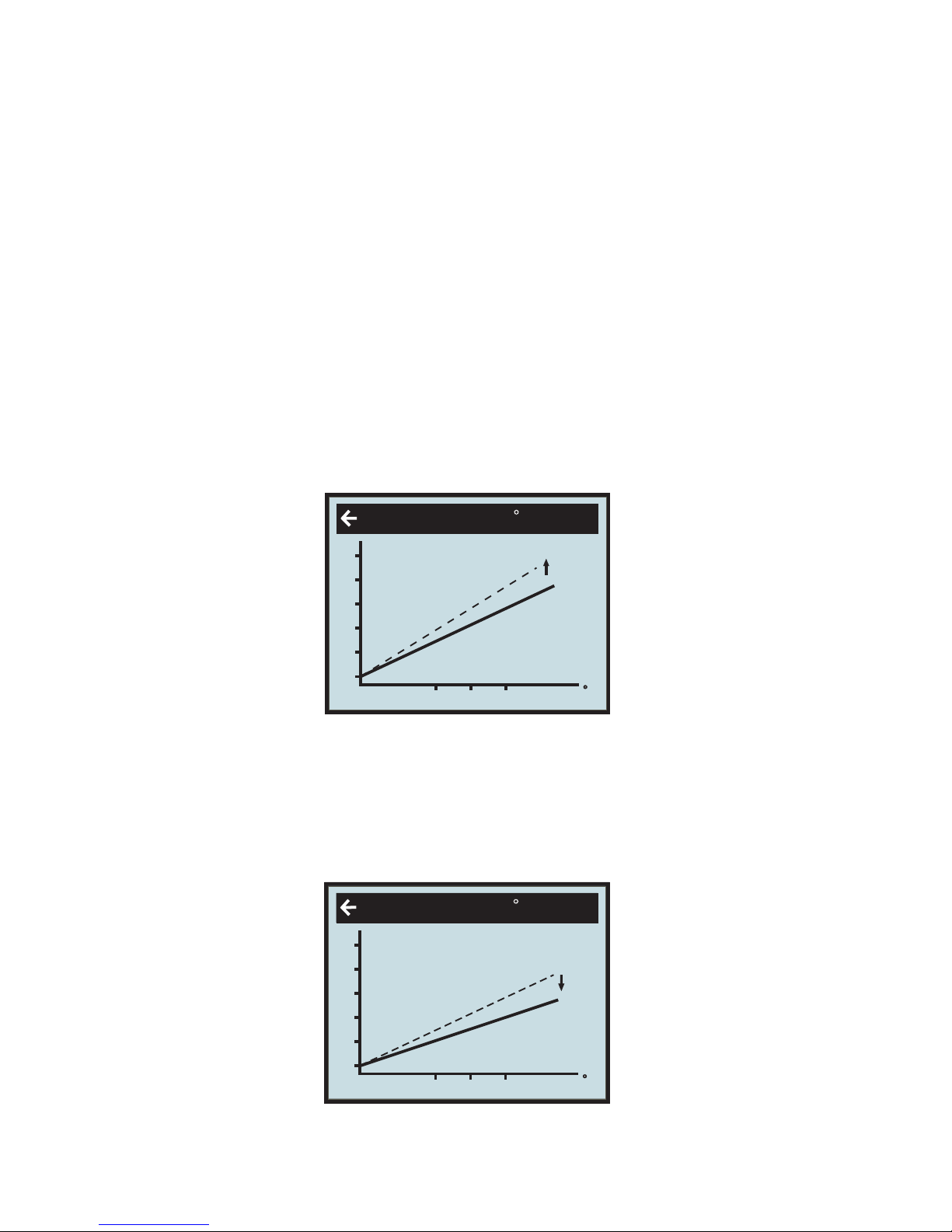
When enter ‘Room heat’ mode, user could control compressor and electrical heater through
regulate heat curve or DM (degree minute).
under a certain ambient temperature ,the time start of compressor is determined by degree
minute(DM).
Now we are giving two situations to explain.
1. ‘start quickly’ is determined by FEED(heat curve)
Suppose now the feed water temperature is 25ć; regulate the heat curve to let the setting of water
temperature to be a higher value such as 55ć,that is FEED25(55). At that time, DM (degree
minute) decrease -30 per minute, when the DM reach -60, compressor will start right away.
(Notice: if the water temperature setting is lower than feed water temperature DM would turn
to positive number, and then compressor does not start. Of course, you also can regulate the DM to be
near the value for compressor start, such as -20.
turn it up
2. ‘start slowly’ is determined by FEED(heat curve)
Suppose now the feed water temperature is 25ć,if regulate the heat curve to let the setting of water
temperaturetobealowervaluesuchas30ć, that is FEED25(30); at that time, the DM would decrease -
10 per minute, the time to reach -60 is becoming longer, only after some time, then
compressor can start. You also can regulate the DM to be more far away from the value for compressor
start, such as (-100).
curve is a little flat
When enter room heat mode, it needs customer to regulate the heat curve or DM (degree minute)
according to own request.
If you wish
to
change the ROOM value:
1
Press the ”up” or ”down” button once
to
open the ROOM value
for
adjustment.
2
Incr
ease or r
educe the pr
eset value using the ”up” or ”down” button so that the
desired room temperature is
r
eached. W
ait
for 10
seconds or pr
ess the left-hand button once
to return
to
the main menu.
Page 21
21
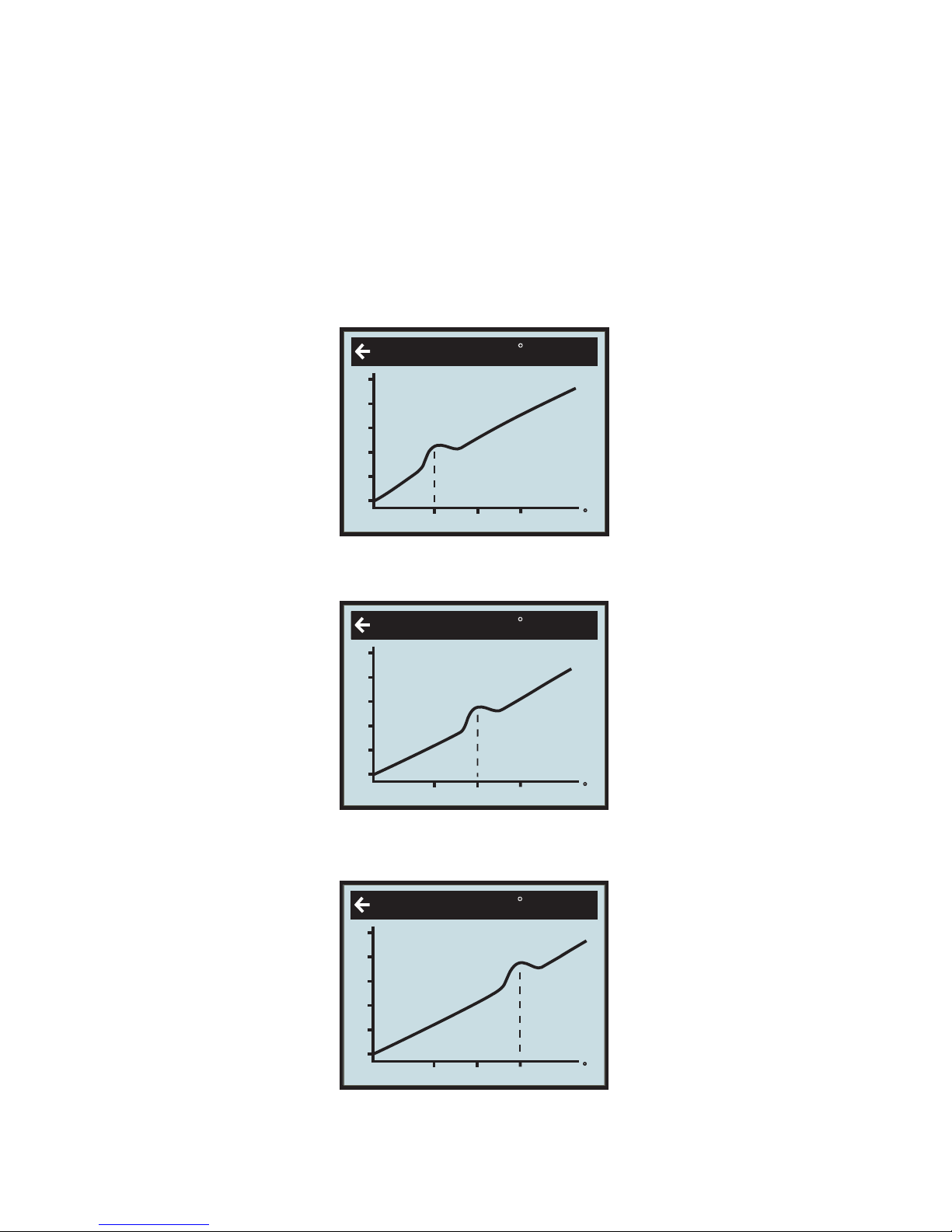
Adjustment of Part of the Heat Curve
At outdoor temperatures between -5°C and +5°C part of the heat curve may need adjusting if the indoor
temperature does not stay at the preset ROOM value. For this reason, the control system includes a
function adjusting the curve at three outside temperatures: -5°C, 0°C, +5°C. This function will allow you
to increase or reduce the feed line temperature, without affecting the heat curve, at three specific outdoor
temperatures. If, for example, the outside temperature is -5°C, the feed line temperature will
change gradually in the outdoor temperature range of 0°C to -10°C, maximum adjustment being reached
at -5°C. The diagram below shows an adjusted CURVE -5. The point of maximum adjustment is clearly
visible.
As we have seen, you can choose to adjust the heat curve at three specified out- side air temperatures:
-5°C,0°C and +5°C. The feed line temperature can be changed by plus/minus 3 degrees.
When outdoor ambient temperature is 5ć, this setting is available to change the feed water temperature,
it is adjustable by operator: heat curve is not change (the slope is no change), but the point near 5ć
(from 0ć to 10ć), curve can be change step by step; the variable is the biggest at 5ć,itis f3ć
.
When outdoor ambient temperature is 0ć,this setting is available to change he feed water temperature,
it is adjustable by operator: heat curve is not change ( the slope is not change), but the point near 0ć
(from -5ć to +5ć), curve can be change step by step; the variable is the biggest at 0ć,it is f3ć.
When outdoor ambient temperature is -5ć,this setting is available to change he feed water temperature,
it is adjustable by operator: heat curve is not change ( the slope is not change), but the point near -5ć
(from 0ć to -10ć), curve can be change step by step; the variable is the biggest at 0ć,it is ±3ć.
CURVE C
C
C
0
5
-5
24
32
40
48
56
64
18
43 3
CURVE C
C
C
0
5
-5
24
32
40
48
56
64
18
34 0
CURVE C
C
C
0
5
-5
24
32
40
48
56
64
18
45 0
3.2.4
Page 22

22
3.2.5
If you wish to change a specific part of the heat curve:
1. Open the main menu INFORMATION by pressing the right-hand button once. You will find the cursor
at the sub- menu OPERATION.
2. Press the ”down” button to move the cursor to the sub-menu HEAT CURVE.
3. Open the selected menu by pressing the right-hand button once. You will find the cursor at the
parameter CURVE.
4. Using the ”up” or ”down” button, select either CURVE 5, CURVE 0 or CURVE -5.
5. Open the selected curve by pressing the right-hand button once.
6. Raise or lower the value, using respectively the ”up” or ”down” button. To return to the main menu,
press the left- hand button three times.
Adjustment of the MIN and MAX value
The MIN and MAX value is the lowest respectively highest value that is allowed for the supply line
temperature. Adjusting the minimum and maximum supply line temperature is particularly important if
your home has floor heating. If your house has floor heating and parquet floor, the supply line
temperature should not be higher than 45°C. Else the floor might get damaged. If you have floor coils
and stone tiles, the MIN value should be 22-25°C in summer when no heating is required to obtain a
comfortable floor temperature.
MIN
MIN is the minimum setting of feed water temperature; it is adjustable by operator from10 to 30 ć,
factory setting is 22ć; if the room’s floor use ceramic tile, then the setting of MIN can not less than
22ć (this value can get a comfortable floor temperature); the heat pump will restart as soon as
actual feed water temperature less than MIN setting.
MAX
MAX is the maximum setting of feed water temperature, it is adjustable by operator from 30 to 70ć,
and factory setting is 70ć; if heat pump is using for floor heating, this setting is very important,
because at the time the feed water temperature can not higher than 70ć, otherwise could be
dangerous; the heat pump will stop as soon as actual feed water temperature more than MAX
setting.
1. Open the main menu INFORMATION by pressing the right- or left-hand button once. You will find the
cursor at the sub-menu OPERATION
2. Press the ”down” button to move the cursor to the sub-menu HEAT CURVE
3. Open the selected menu by pressing the right-hand button once. You will find the cursor at the
parameter CURVE.
4. Press the ”down” button to move the cursor to MIN.
5. Open the selected parameter by pressing the right-hand button once. The cursor is at MIN
6. Raise or lower the value, using the ”up” and ”down” button respectively.
7. Press the left-hand button three times to return to the main menu.
Repeat the procedure to change the MAX value, replacing MIN by MAX at step 4.
If there is a basement to your house, the MIN value should be adjusted to a suitable temperature in
summer too, to avoid a humid and chilly basement. In such cases, the value for HEAT STOP needs
being adjusted upwards. If you wish to change the MIN or MAX value:
Page 23
23
3.2.6
Adjustment of the HIGH T STOP and LOW T STOP
The HIGH T STOP and LOW T STOP
function
stops water production to room floor
when the outside air
temperatur
e
is
equal
to
higher or lower than the value entered for
HIGH T STOP or LOW T STOP. When the
function
is
activated,
the
cir
culation pump will be turned of
f. The factory setting of the HIGH T STOP is 50°C.( 0 ~ 50 °C adjustable )
If you wish
to
change the HIGH T STOP OR LOW T STOP
value:
1
Open the main menu INFORMA
TION by pr
essing the right- or left-hand button once.
You
will find the cursor at the sub-menu OPERA
TION
2
Press the ”down” button
to
move the cursor
to
the sub-menu HEAT
CURVE
3
Open the selected menu by pr
essing the right-hand button once.
4
You will find the cursor at the parameter CURVE.
5
Press the ”down” button
to
move the cursor
to
HIGH T STOP or LOW T STOP.
6
Open the selected parameter by pr
essing the right-hand button once.
The cursor moves
to
7
Raise or lower the value, using r
espectively the ”up” or ”down” button.
8
Pr
ess the left-hand button thr
ee times
to return
to the main menu.
3.2.7
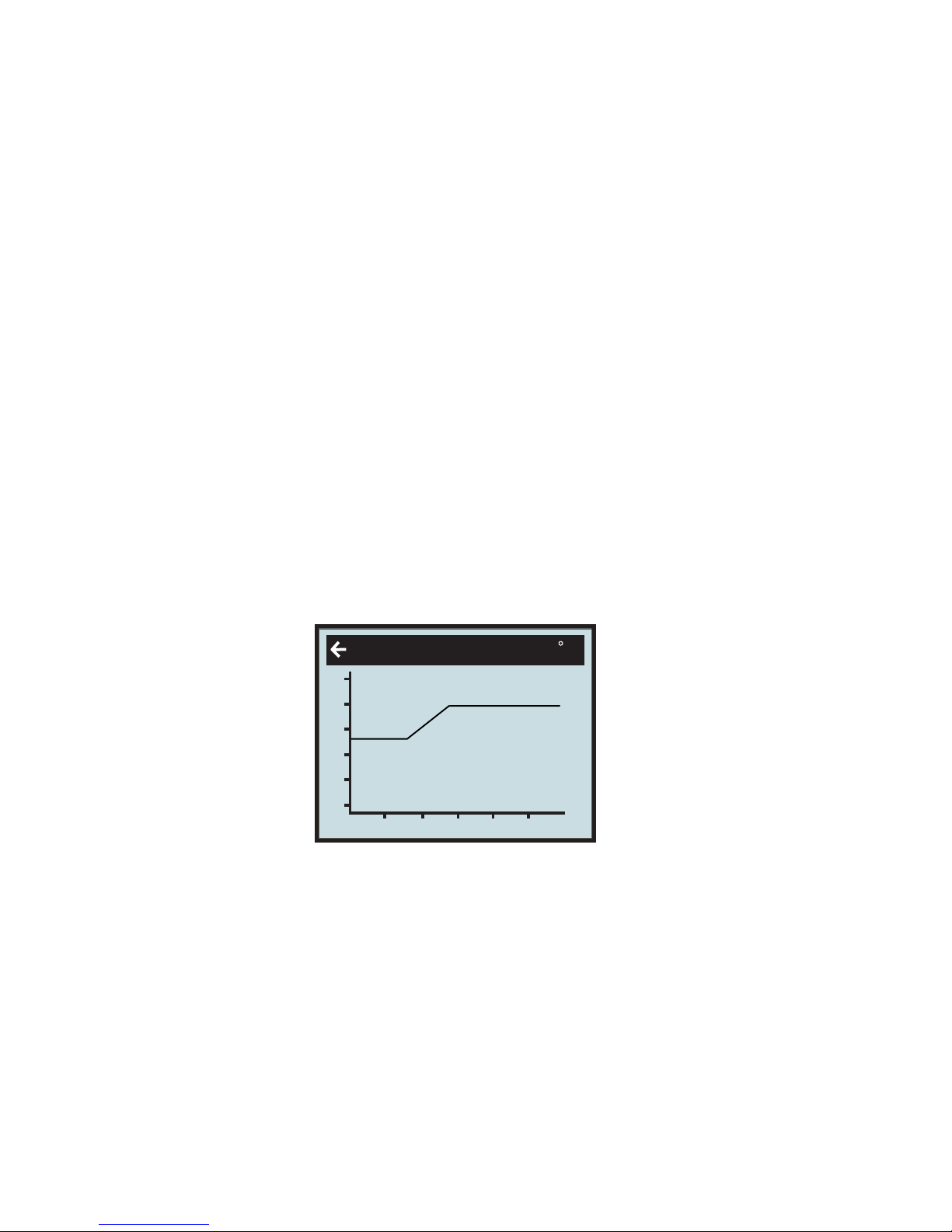
Graph of r
ecent changes in TEMPERA
TURE
All temperatures registered
during the last hour can be viewed in the sub-menu TEMPERA
TURE in the shape of a
graph. This will enable you
to
monitor changes in the dif
fer
ent system temperatures.
There is a graph available
for
all temperatures, except
for
the OUT / ROOM temperature,
where
you can only
view the
measured value. The integral value that is displayed repr
esents the heating system’s energy
balance.
If you wish
to
check the TEMPERA
TURE graphs:
1
Open the main menu INFORMA
TION by pr
essing the right- or left-hand button once.
You
will find the cursor at the sub-menu OPERA
TION.
C
30
-16
0
16
32
48
64
60
48
FEEDLINE
2
Press the ”down” button
to
move the cursor
to
the sub-menu TEMPERA
TURE
3
Open the menu by pr
essing the right-hand button once.
4
You will find the cursor at the parameter OUT.
5
Press the ”down” or ”up” button to move the cursor to the desired temperature.
6
Open the selected value by pr
essing the right-hand button once. A
graph will be shown in the display.
7
Move the cursor along the time axis using the ”up” (plus) or the ”down” (minus) button.
The exact temperature at the selected point of time appears at the top of the display.
8
Press the left-hand button three
times
to return
to
the main menu.
The factory setting of the LOW T STOP is -50°C.( -50 ~ 0 °C adjustable ) .
HIGH T STOP
or LOW T STOP.
‘HIGH T STOP’ and ‘LOW T STOP’ functions are only for room heating, the water tank
normally when the two functions are active.
heating still works
Page 24
3.3 Maximum Return Line T
emperature
The maximum r
eturn line temperature, i.e. temperature of
the water r
eturning fr
om
the heating system, should
be adapted
to
each individual installation. The
corr
ect
temperature
value
for
your system will be entered by
your
installation contractor in
connection with installation and can be adjusted later.
3.4 W
arm W
ater Pr
oduction
The temperature of
the water distributed
to
the water heater is contr
olled by the regulating pr
essure
switch
and cannot be adjusted.
Reading of warm water temperature.
To
check the actual warm water temperature on
the display:
1
Open the main menu INFORMA
TION by pr
essing the right- or left-hand
button once.You will find the cursor at the
sub-menu OPERA
TION.
2
Press the ”down” button
to
move the cursor
to
the sub-menu called TEMPERA
TURE.
3
Open the menu by pr
essing the right-hand button once.
4
Press the ”down” button to move the cursor to the parameter WARMWATER.
5
Open the selected parameter by pr
essing the right-hand button for 3 seconds.
A graph will be shown of last hour’s
warm water temperatures.
6
Press the left-hand button three
times
to return
to
the main menu.
The value displayed next
to
the parameter WARMWATER is the actual hot water temperature. The value in brackets is
the temperature at
which warm water production will start.
When the actual temperature
falls below that value, warm
water pr
oduction star
ts. The star
ting value is not adjustable.
3.5 Regular Checks
3.5.1 Check of Operating Mode
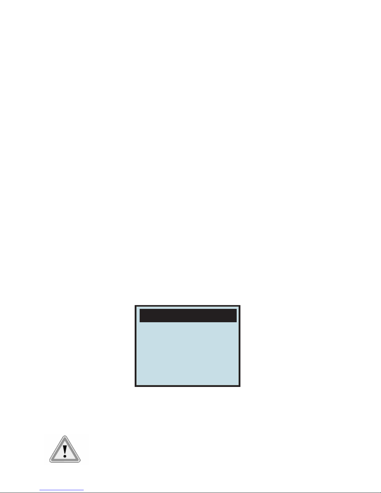
In the event of an alarm, The background light of LCD will flash and an alarm message will be displayed.
Check
the alarm indicator r
egularly
to
make sure
that the heat pump works properly. You would not always notice if
there is
something wrong, as the auxiliary
heater would start
automatically (pr
ovided, of course, operating mode
AUTO was
selected). For more
information, please r
efer
to
the chapter TROUBLE SHOOTING on p.
26.
3.5.2 Checking the Brine Level in the Brine sys tem
The Brine system must be filled with the
corr
ect volume of
brine. Otherwise the heat pump
unit risks being damaged.
24
ALARM
AND.HEAT OVER
OR FLOW TROUBLE
Page 25
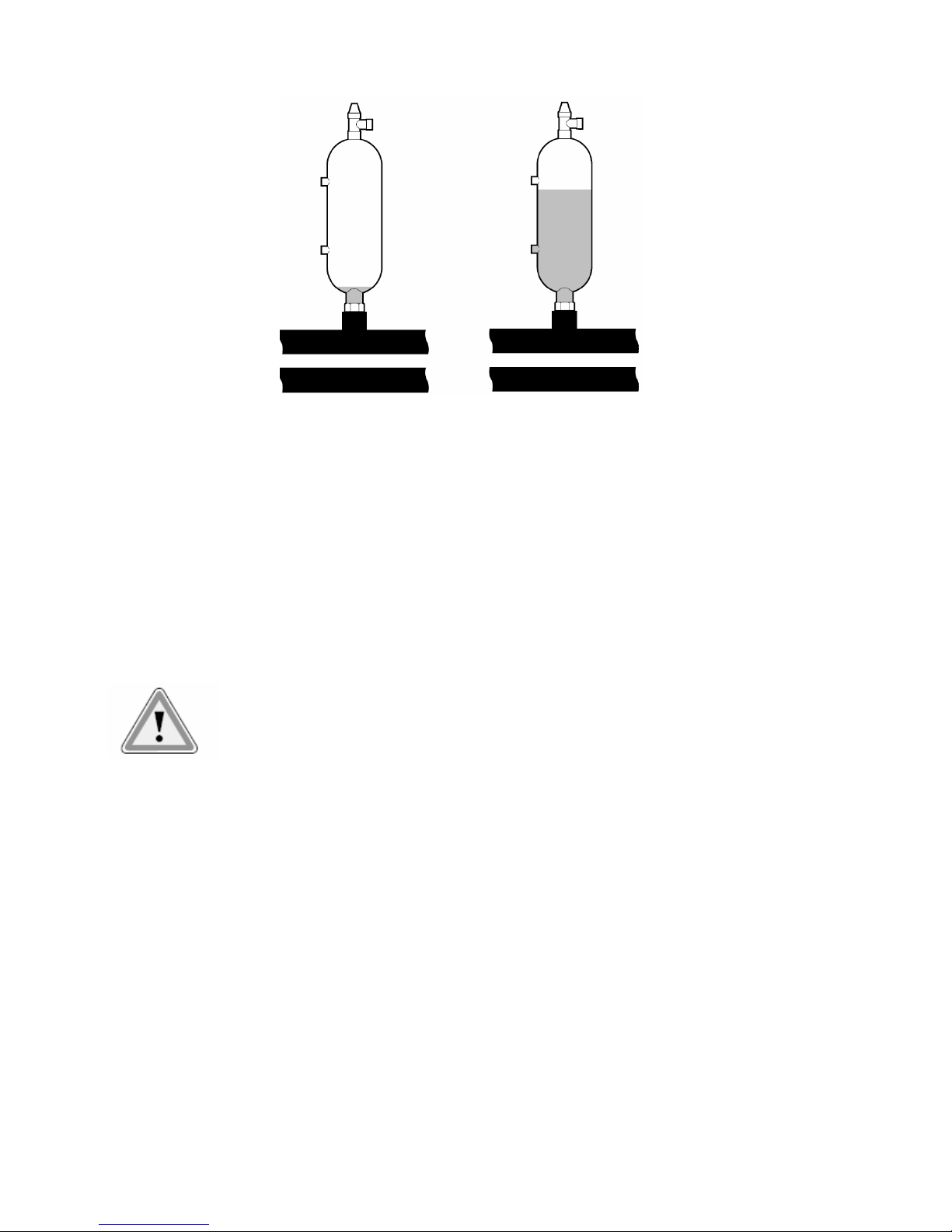
Brine system liquid (brine) must be added if the brine level gets so low that it is no
longer visible in the expansion
vessel.
Level is too low Level is correct
During the
first
month of operation the brine level might sink a little, which is quite normal. The brine level
may also vary a bit, depending on the temperature of
the
heat sour
ce. Under no
cir
cumstances, however,
shall
the
brine level be allowed
to
sink so much that it is no longer visible in the expansion vessel.
Call your installation contractor
for refilling of Brine system liquid. (See ”Refer
ences” on page 28.)
3.5.3 Checking the W
ater Level of the Heating System
The pr
essure of
the heating system should be checked once monthly.
The pr
essure, shown on the external pr
essure
gauge, should be 1-1,5 bar. If
the value is below 0.8 bar with cold water in the heating system, more
water must be
added (applies
to a
closed expansion vessel). To
find out where
the pr
essure
gauge is located.
You
can use or
dinary tap water
for
filling the heating system. In some rare
cases the water quality would be
unsuitable
for
this purpose (corr
osive or calcar
eous water). In case of doubt, we would r
ecommend that you call
your installation contractor.
25
Don’t use any water tr
eatment additives
for
the heating system!
3.5.4 Checking the Safety V
alves
Both safety valves of the heating system should be checked at least four times a
year
to prevent lime deposits
to
clog the mechanism. To
find out where
the safety
valves are
located.
The safety valve of the water heater protects the closed heater against positive pressure. It is
fitted on the cold
water inlet line, its outlet opening facing down- war
ds. If the safety valve is not checked r
egularly,
the water heater
might be
damaged. It is quite normal that the safety valve lets out small amounts of water
when the water heater is
being char
ged, especially if a lot of warm water was used previously.
To
check the safety valves, give the cap a quar
ter of a turn clockwise until the
valve lets out some water thr
ough
the overflow pipe.
If a safety valve does not work pr
operly, it
must be r
eplaced. Check with your
installation contractor.
See ”Refer
ences” on page 28.
The opening pr
essure of
the safety valve is not adjustable.
3.5.5 In the Event of Leakage
In the event of leakage in the warm water lines between unit and water taps, the
shut-off
valve on the cold water
inlet line should be closed immediately.
Call your installation contractor (see ”Refer
ences” on page 28). In the event of
leakage in the sytem
cir
cuit, turn
off
the heat pump and call your
installation contractor immediately.
See ”Refer
ences” on page 28.
Page 26

26
4 Trouble shooting
4.1 Alarm Messages
In the event of an alarm message, try
to re-start
the unit with the safety switch.
If this does not work, try
to
solve the pr
oblem with the help of the table below. Call your installation contractor if
you need help. See ”Refer
ences” on page 28.
T
able 3: Alarm Messages
Error code Explanation Cause How to do
RETURN TEMP
Return water temperature
sensor
error;
Sensor disconnected; Sensor
was
defective.
Check the connections, the wire of sensor, or change the sensor.
Under 25
°C
, the resistance of sensor should be 5K
FEEDLINE TEMP
Supply water temperature
sensor error;
Sensor disconnected; Sensor
was
defective.
Check the connections, the wire of sensor, or change the sensor.
Under 25
°C
, the resistance of sensor should be 5K
OUTDOOR TEMP
Outside air temperature
sensor error
Sensor disconnected; Sensor
was
defective.
Check the connections, the wire of sensor, or change the sensor.
Under 25
°C
, the resistance of sensor should be 5K
ROOM TEMP
Room air temperature
sensor error;
Sensor disconnected; Sensor
was
defective.
Check the connections, the wire of sensor, or change the sensor.
Under 25 °C, the resistance of sensor should be 5K
CMP TEMP
Compressor exhaust
temperature sensor error;
Sensor disconnected; Sensor
was
defective.
Check the connections, the wire of sensor, or change the sensor.
Under 25 °C, the resistance of sensor should be 50K
WARM WATER TEMP
Water tank temperature
sensor error
Sensor disconnected; Sensor
was
defective.
Check the connections, the wire of sensor, or change the sensor.
Under 25 °C, the resistance of sensor should be 5K
HIGH PRESS (single
compressor system)
COMP.A PRESS(double
compressor system)
Compressor high
pressure protection
The wire disconnected; lack of
refrigerant;
water flow stop in the room cycle
Check
the wire connection; check refrigerant quantity; Check the
water cycled pump for the room heating system;
Check if the
water system contains air
LOW PRESS (single
compressor system)
COMP.B PRESS(double
compressor system)
Compressor low
pressure protection
The wire disconnected; lack of
refrigerant;
Check the wire connection; check refrigerant quantity;
CMP OVER
Compressor overload
The actual current over the
contactor‘s allowed current.
Compressor
current too large;
Check the wire connection;
Check if the water system contains air, and cause the water
temperature over high and current over large
ADD HEAT OVER OR FLOW
TROUBLE
Supplementary
electrical heater over
heat or water flow got
problem
The temperature of electrical heater
over the max allowed temperature.
Water flow too small or stopped.
Check the wire connection;
Check if the water system contains air or without water
CMP AIR OVER
Compressor exhaust air
temperature over heat
Water flow too small;
Lack of refrigerant
Check if the water system contains air or without water
Check the refrigerant quantity
WARMWATER TEMP TOO LOW
Temperature of the water
tank is too low.
Water tank temperature less than
10
ć
A . During heat pump running, whatever mode heat pump runs, hea
t
pump will give an alarm with sound, at the time, heat pump will
automatically turn to water tank heating, and
then go back to previous running mode until water tank’s
temperature get to 20
ć
B . During heat pump is not running, heat pump will give an alarm
with sound: WARM WATER. TOO LOW
POWER SUPPLY
Phase error
For three-phase, the phase or
der
r
eversed or wrongly connected. For
single-phase, the “ three-phase
option Port” in the circuit board is not
connected or loose.
Please check if the phase connections were correct.
Page 27

27
Table 6
The following table only applies
to
installations using gr
ound water as brine system liquid.
cuit filled with Brine sytem (see above), transporting heat
energy from heat source
to
heat pump.
(See ”Heat Pump
Principle” on p. 4)
5
Terminology and Abbr
eviations
the evaporator,
energy from the heat source is absorbed by the r
efrigerant passing thr
ough
the
evaporator.
The r
efri
gerant turns into gas. (See ”Heat Pump Principle” on p. 4).
is
the heat balance of the heating system. Production of heat is r
egulated acc.
to
a calculated heat demand value. This value is determined by comparing the
actual supply
line temperature
with its calculated (setpoint) value. The dif
fer
ence between the two values
is multiplied by the time during which the dif
fer
ence is active. The r
esul- ting value is r
eferred
to
as the integral. The integral value is automatically established when heat is being
pr
oduced. The value can be viewed in the sub-menu TEMPERA
TURE.
compr
essor raises temperature
and pr
essure of
the the refrigerant (See ”Heat Pump
Principle” on p.
4).
the condenser,
the r
efrigerant r
eleases its heat energy to
the heating
cir
cuit. (See ”Heat
Pump Principle” on p.
4)
CURVE value will be adjusted on the control
panel. The value indicates the temperature
of the water distributed
to
the radiators (supply line temperautre) at an
outside air
temperature of
0°C.
cuit in the heat pump filled with r
efrigerant that by evapo
ration, compr
ession, and
condensation absorbs heat ener
gy from the sytem
cir
cuit and r
eleases it
to
the
Heating circuit.
Radiator Heating element
Control he control
computer r
egulates the whole installation. All system settings
and
computer
temperatur
e changes ar
e stor
ed and r
egistered in
the computer. Settings are
adjusted
ia
the graphic display on the control
panel.
Heating circuit he heating
cir
cuit r
eceives heat energy from the r
efrigerant
cir
cuit and
carries it
to
the water
heater or radiator/ floor coil systems. (See further
”Heat Pump Principle” on p.4).
Heat curve he heat curve is the control
computer’s instrument
for
determining the required supply line
temperature of
the heating system. Indoor temperatur
e will be adjusted by adjustment of the
CURVE value
Condenser In
Compressor The
CURVE The
Refrigerant Cir
circuit
T
T
T
INTEGRAL INTEGRAL
Evaporate In
v
Brine system Cir
Error code Explanation Cause How to do
BRINE OUT TEMP
Brine out temperature
sensor error;
Sensor disconnected; Sensor
was
defective.
Check the connections, the wire of sensor, or change the sensor.
Under 25
°C
, the resistance of sensor should be 5K
BRINE IN TEMP
Brine in temperature sensor
error; All operation stopped.
Sensor disconnected; Sensor
was
defective.
Check the connections, the wire of sensor, or change the sensor.
Under 25
°C
, the resistance of sensor should be 5K
Page 28
28
6 Default Settings
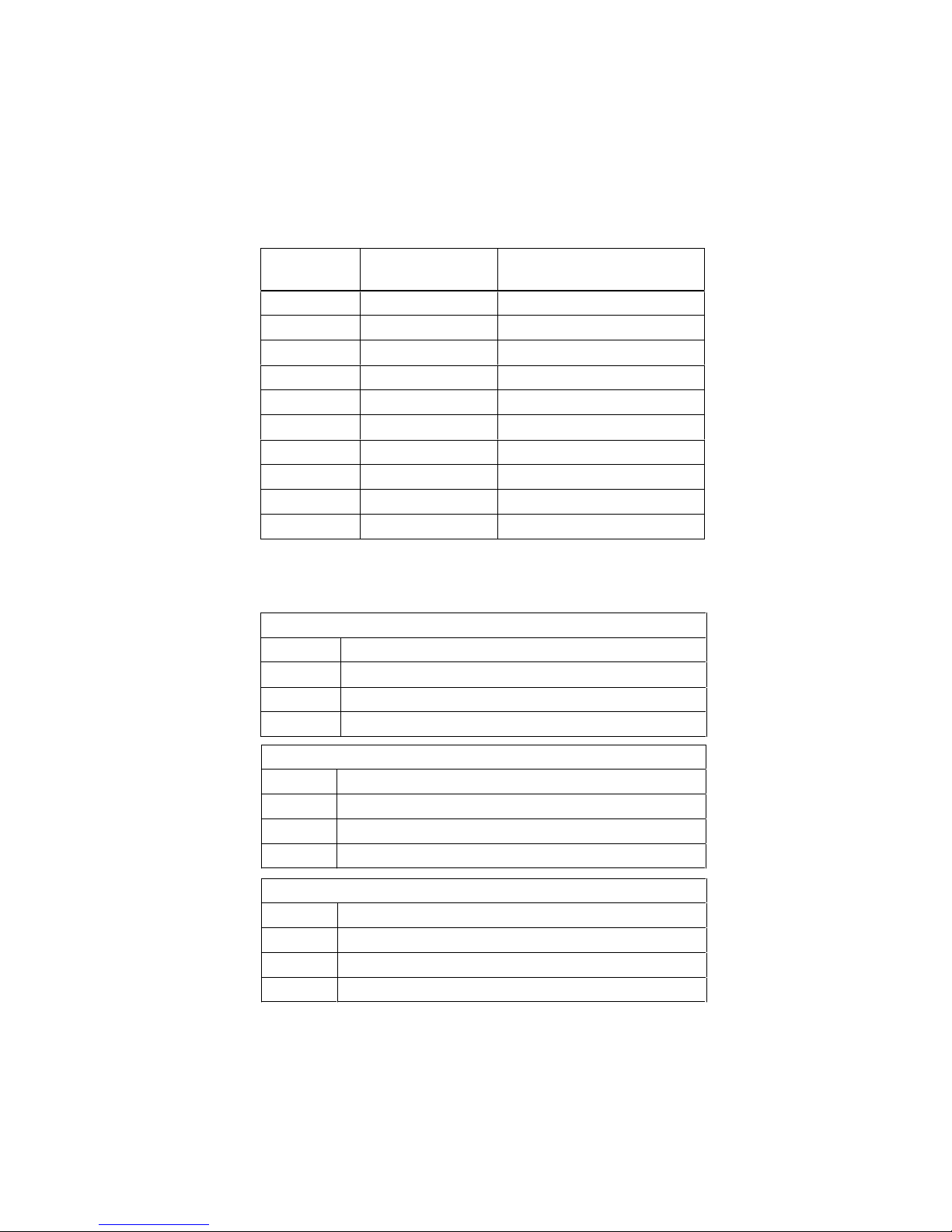
The
first
column of table 7 shows the parameters that are
adjustable by the User. The second column shows
settings made at the factory and the third column the
settings made by the installation contractor in connection
with installation of the
heat pump.
Make sure
that the installation contractor enters any settings made during
installation that are
particular
for
your
heat pump. This will make it easier
for
you
when you make your own adjustments
.
T
able 7: Default Settings
7 Refer
ences
Installation and commissioning by:
Piping installation
Date:
Company:
Name:
Phone:
Parameter
Factory setting
Individual settings by
installation
contractor
ROOM
20°C
OPERA
TION
AUTO
CURVE
40°C
MIN
22°C
MAX
70°C
CURVE 5
0°C
CURVE 0
0°C
CURVE -5
0°C
HIGH T STOP
50°C
Electric installation
Date:
Company:
Name:
Phone:
System Adjustment
Date:
Company:
Name:
Phone:
I
f these instructions are not followed during installation,operation, and maintenance, the obligations of
our company
under the warranty regulations are no longer binding
.
Our company reserves the right
to
alter any details and specifications without prior
notice.
LOW T STOP
-50°C
Page 29

 Loading...