


SERIAL CABLES NVMe JBOF User’s Manual
PCI-ENC8G-024U NVMe
2U24Bay JBOF
User’s
Manual
Revision 1.2

SERIAL CABLES NVMe JBOF User’s Manual
Preface
Change Notice
The information in this document is for information purposes only, it is subject to change
without notice ahead.
SAFETY PRECAUTIONS
Please read this section carefully before proceeding. These precautions explain the correct and safe
use of this device, thereby helping to prevent injury to you or others, and also help you to minimize
the risk of damaging the device.
Warnings
Always follow the basic warnings listed here to avoid the risk of serious injury or death from
electrical shock, short-circuiting, fire, and other hazards. These warnings include, but are not
limited to:
. With the exception of the user-swappable parts, do no attempt to disassemble or modify the
enclosure. If this device appears to be malfunctioning, contact Serial Cables Customer Service.
. Do not drop the enclosures or any of its drive modules; dropping or mishandling of the enclosure
or drive modules may result in a malfunction.
. Do not insert your fingers or foreign objects inside the enclosure; take particular care when small
children are present.
. Do not expose the device to rain, use it near water or containers that contain liquids which might
spill into any openings, or in damp or wet conditions.
. If unusual smells, sounds, or smoke come from the device, or if liquids enter it, switch it off
immediately and unplug it from the electrical outlet.
. Follow the instructions in this manual carefully; contact Serial Cables Customer Service for
additional advice not covered in this User’s Guide.
Copyright© 2017 by SERIAL CABLES, LLC. All rights reserved

2.3
SERIAL CABLES NVMe JBOF User’s Manual
Table of contents
1. Introduction
1.1 Ov erv i ew …… … ……… …… … ……… … … ……… … … … ……… … ……… . … …… …… … …… … …… . …… P1
1.2 Pa c kage C he c k lis t…………… … … … ……………… … … … … …. ……………… … … … …… … …… .…… P1
2. Hardware Installation
2.1 Pa n e l La y o ut …… … … … ……………… … …………… … …… …… ………… … … … ………… … … … ……… P2
2.2 En clos u r e Setup… … … …………… … … … …… … ………… … … … …… ……………… … … …… ………… P 3
Comp o n e n t s loc a t i o n defi n i t io n… …… …… ………… … … … ………………… … …… …… ………. P5
2.4
3. LCD Configurations
Switc h m o de selec t i on …… …… …… …………… … … … …… … ………… … … … ……………… … … … P6
3.1 Function key definitions…… … … … …… ………… … … … ………… … … … ………… … … …………… … …… P9
3.2 LCD configuration main menu………… … … …… …… …………… … … … …………… … … … …… ……… P10
4. CLI Manager
4.1 St a r t -up VT100 Sc reen……………… … … … …… … … … …… …… …… …. . …… … … … … … … …… … P12
4.2 CLI Co m m a nd … … … … … … … … …… … … … … … …… ………………………………………….……………… P16
5. Firmware Upgrade………………………………………………………… …… … . … … … … … …… … … . … ……… …… P 3 8

1
SERIAL CABLES NVMe JBOF User’s Manual
1.
NTRODU
I
CTION
1.1 Overview
PCI-ENC8G-024U 2U24bay PCIe NVMe JBOF enclosure is designed to provide an external NVMe
storage solution. The enclosure is equipped with two PCIe switch controllers, supporting a total
of twenty-four (24) high-speed SFF-8639 NVMe SSDs. Each controller integrates the Avago
Technologies ExpressFabric Capella 2 PCIe switch PEX9781 with eight external mini-SAS HD
connectors, designed to provide PCIe expansion. The total maximum bandwidth is PCIe Gen3
x64 512GT/s and allows up to 8 head-nodes access the NVMe JBOF enclosure.
1.2 Package Checklist
Before the installation of the enclosure, verify the items below are included in the package.
A. Enclosure × 1 B. HDD tray (installed in the PCI-ENC8G-024U) ×
24
C. Hard disk drive mounting screw × 96 D: AC Power cord x2
E. Package of slide rail× 1
Visit the website below that gives instructions on how to install the slide rails on enclosure.
https://www.youtube.com/watch?v=s41XnpJoAmA
If any of the items listed above is missing or damaged, please contact the sales representative.

2
SERIAL CABLES NVMe JBOF User’s Manual
2.
ARDWARE INSTALLATION
H
This section gives the layout of the panel and describes the procedures for setting up the
PCI-ENC8G-024U enclosure.
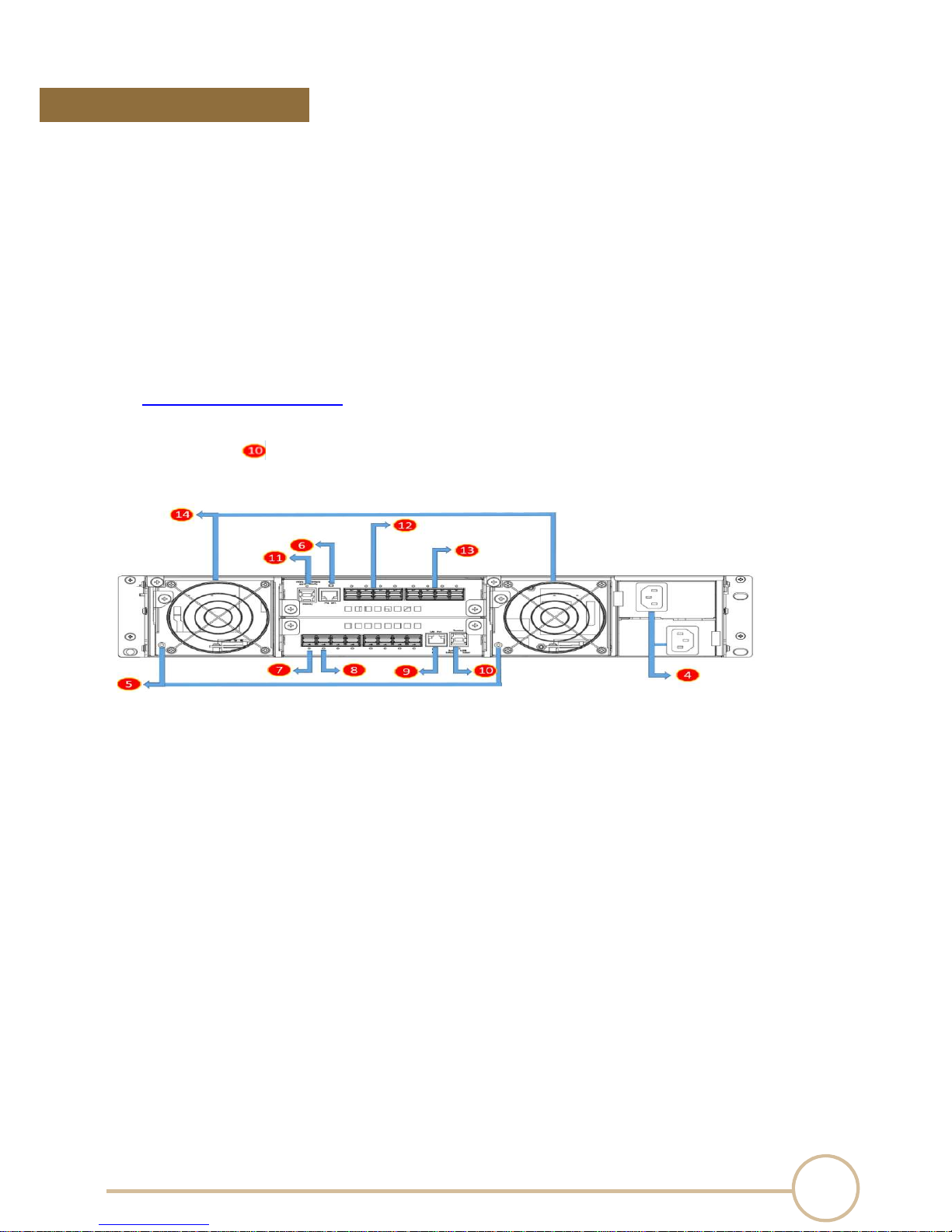
2.1 Panel
Layout
1. Activity indicator LED
‧Flash Blue – Access
‧Red – HDD failure
2. S S D presence LED
‧White – Power On
3. LCD module
4. Power cord receptacle
5. Fan status LED
‧Normal – No light
‧Failure – Red
6. Mute button
‧To mute buzzer beeping of enclosure failure
7. Po r t Li n k w idt h indication LED
‧One Red LED– configure as one x16 port
‧Two Red LEDs—configure as two x8 ports
8. Upstream/Downstream port indication
‧Flash Blue – Downstream port
‧Blue – Upstream port
9. LAN port
10. USB port
11. Sys t em h e alt h y L E D
‧Green – Normal
‧Red – Failure events occurred
12. Quad port m i ni-S AS H D (SF F - 864 4 ) connector
13. Quad port m i ni-S AS H D (SF F - 864 4 ) connector
14. Swappable fan
Note :
When any one of environmental sensors is abnormal or there is a drive status failure, the
buzzer on the PCI-ENC8G-024U switch board will beep. To mute the buzzer, press the mute
button near LAN port at the rear of the enclosure. Environmental sensors include:
Cooling elements (Fan)
i. Temperature elements
ii. Voltage elements
iii. Current element
iv. Power Supply element
3
SERIAL CABLES NVMe JBOF User’s Manual
2.2 Enclosure Setup
1. Remove the PCI-ENC8G-024U enclosure from its packaging, and place the enclosure next to
PC, server, or workstation.
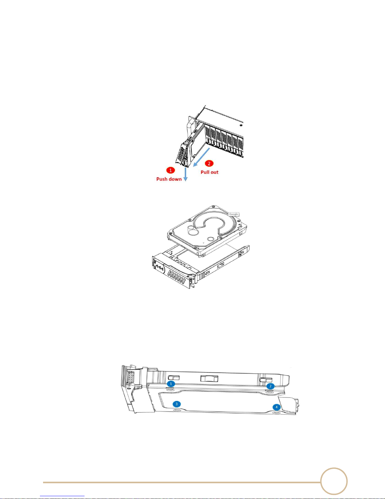
2. Hold one of the drive trays from the enclosure and push its button downward for the release of
the lever until the lever pops out.
3. Place a drive tray on a flat and level surface, and then attach the drive into the tray.
WARNING:
You must verify the heads of the four screws are level with the drive tray while the drive is attached
to the tray; otherwise, a screw may take hold of the tray from the bottom side and prevent you to
pull the tray out of the enclosure.
4. Use four of the screws provided, and fasten the drive on the tray. Tighten each screw to fasten
the HDD snugly to the drive tray. Do not overly tighten the screws.
WARNING:
Do not force the levers to close while you insert drive modules into the PCI-ENC8G-024U enclosure.
If a lever does not close smoothly, draw out and insert the drive module again, and then press the
lever to close.
4
SERIAL CABLES NVMe JBOF User’s Manual
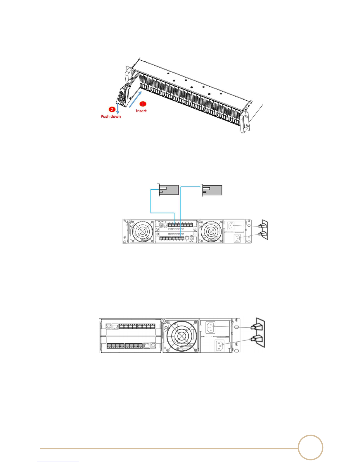
5. Insert the drive module into the PCI-ENC8G-024U enclosure correctly until its lever appears to
shut, and then press the lever to close until it clicks to ensure that the drive module is within
the enclosure.
6. Repeat steps 2 to 5 for further drives.
7. Connect PCI-ENC8G-024U enclosure to the host interface: An external PCIe host adapter card
through an SFF-8644 mini-SAS HD data cable. The connection between the PCI-ENC8G-024U
enclosure and the external PCIe host adapter ports is shown as follows:
8. Connecting PCI-ENC8G-024U enclosure’s USB Port (optional)
‧
PCI-ENC8G-024U enclosure’s system functions can be managed via a COM port running a
VT-100 terminal emulation program, or a VT-100 compatible terminal.
9. The PCI-ENC8G-024U enclosure provides a redundant power supply unit. Connect one end of
the two power cords to the two receptacles on rear of PCI-ENC8G-024U enclosure, and then
connect the other end of the two power cords to the power outlets.
11. After the two power cords are connected, you can power on the PCI-ENC8G-024U enclosure
and the computer.
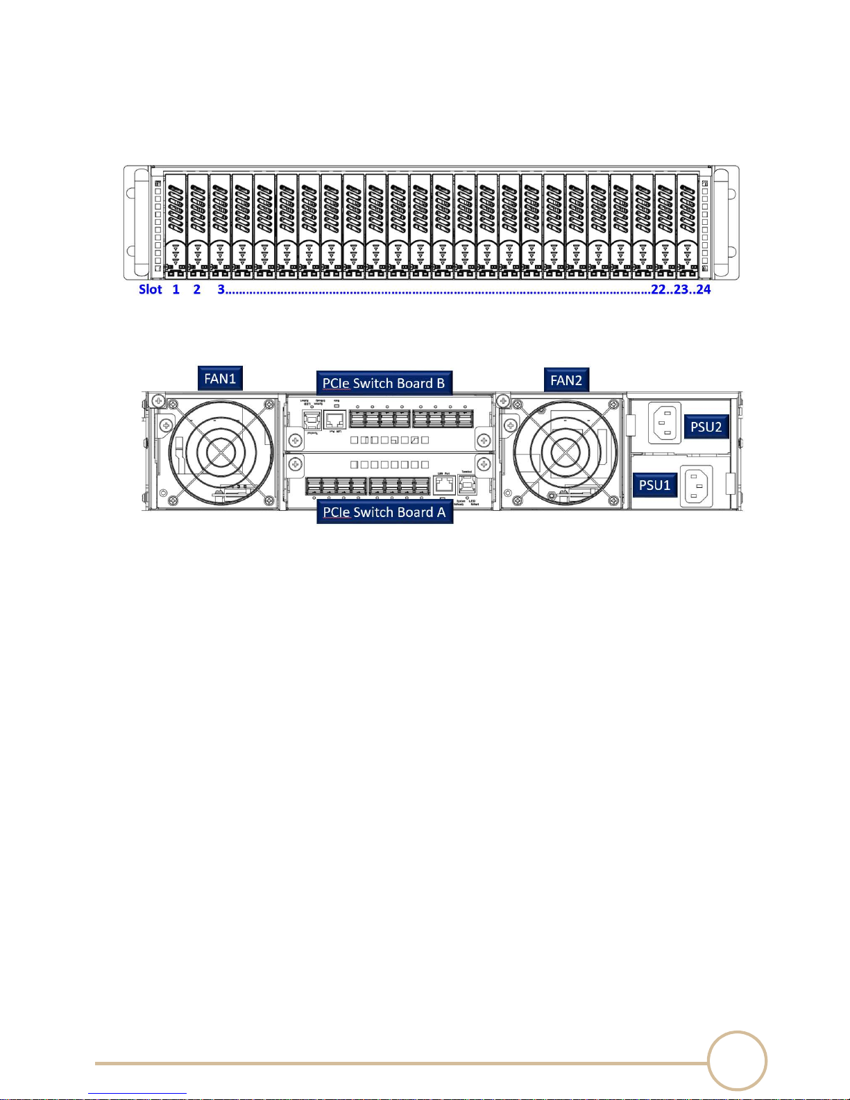
2.3 Components location definition
5
SERIAL CABLES NVMe JBOF User’s Manual
1. Slot location definition
2. PSU, FAN and PCIe switch board definition
2.4 Switch mode selection
6
SERIAL CABLES NVMe JBOF User’s Manual
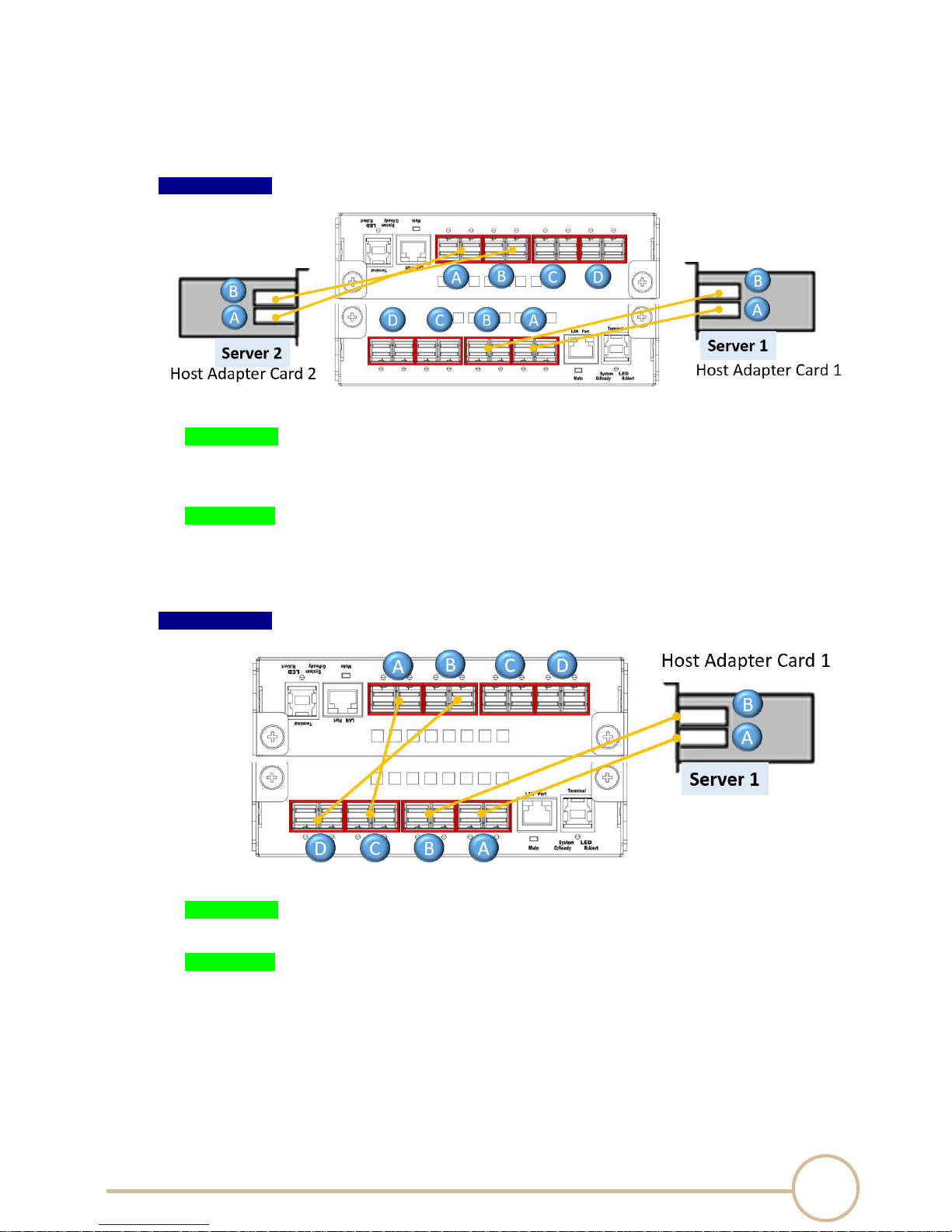
User can utilize the CLI command interface to set the switch’s mode. The 2U24bay NVMe JBOF
supports 3 modes: base mode, Two VR mode, Four VR mode.
1. Mode 1: Base mode, x16 configuration.
Connection A:
Bandwidth:
PCIe switch board A: PCIe Gen3 x16 128GT/s
PCIe switch board B: PCIe Gen3 x16 128GT/s
NVMe SSD:
Server 1 can assess NVMe SSDs in Slot 1 to 12.
Server 2 can assess NVMe SSDs in Slot 13 to 24.
Connection B:
Bandwidth:
PCIe switch board A+B: PCIe Gen3 x16 128GT/s
NVMe SSD:
Server 1 can assess NVMe SSDs in Slot 1 to 24.
7
SERIAL CABLES NVMe JBOF User’s Manual
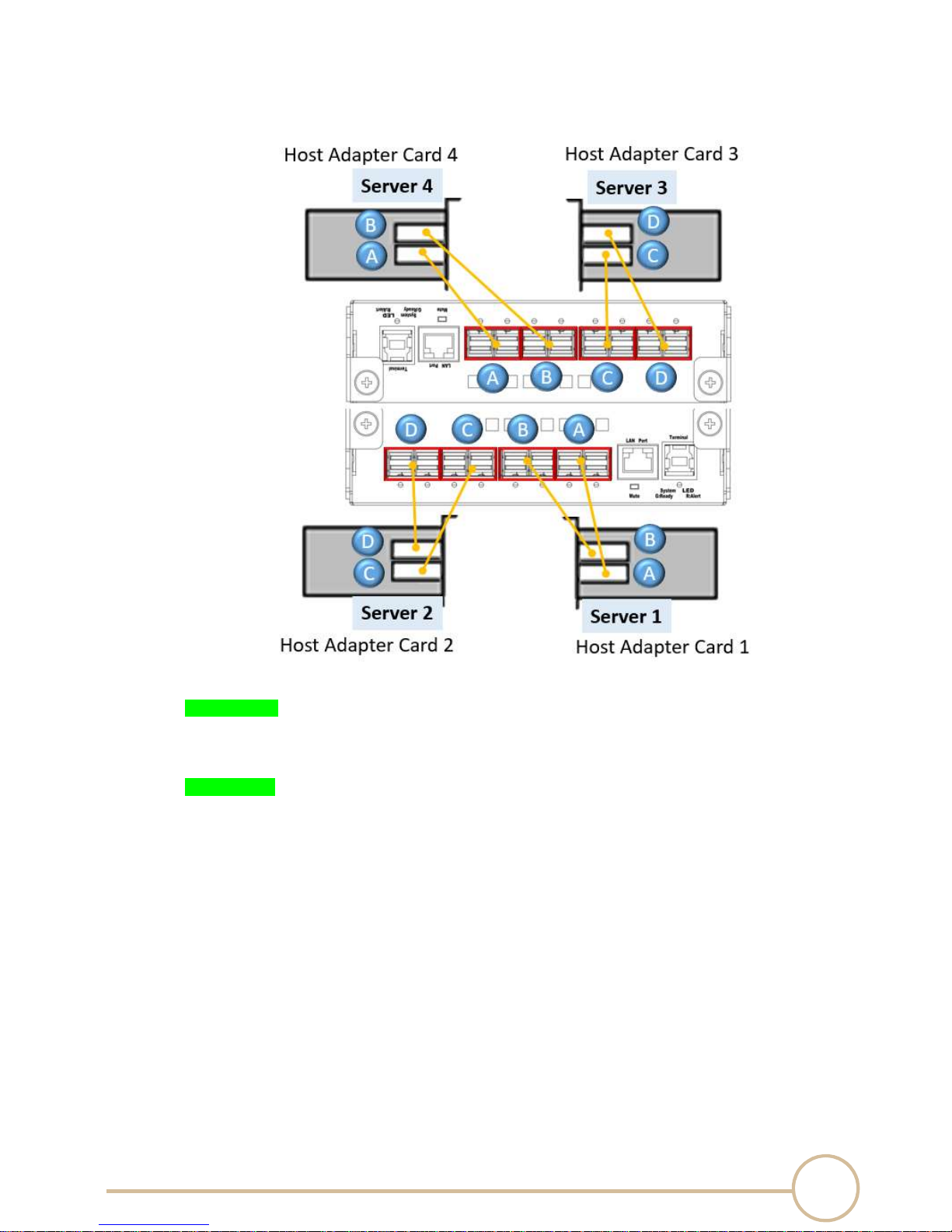
2. Mode 2: Two VR mode, x16 configuration
Bandwidth:
PCIe switch board A: PCIe Gen3 x32 256GT/s
PCIe switch board B: PCIe Gen3 x32 256GT/s
NVMe SSD:
Server 1 can assess NVMe SSDs in Slot 1 to 6.
Server 2 can assess NVMe SSDs in Slot 7 to 12.
Server 3 can assess NVMe SSDs in Slot 13 to 18.
Server 4 can assess NVMe SSDs in Slot 19 to 24.
8
SERIAL CABLES NVMe JBOF User’s Manual
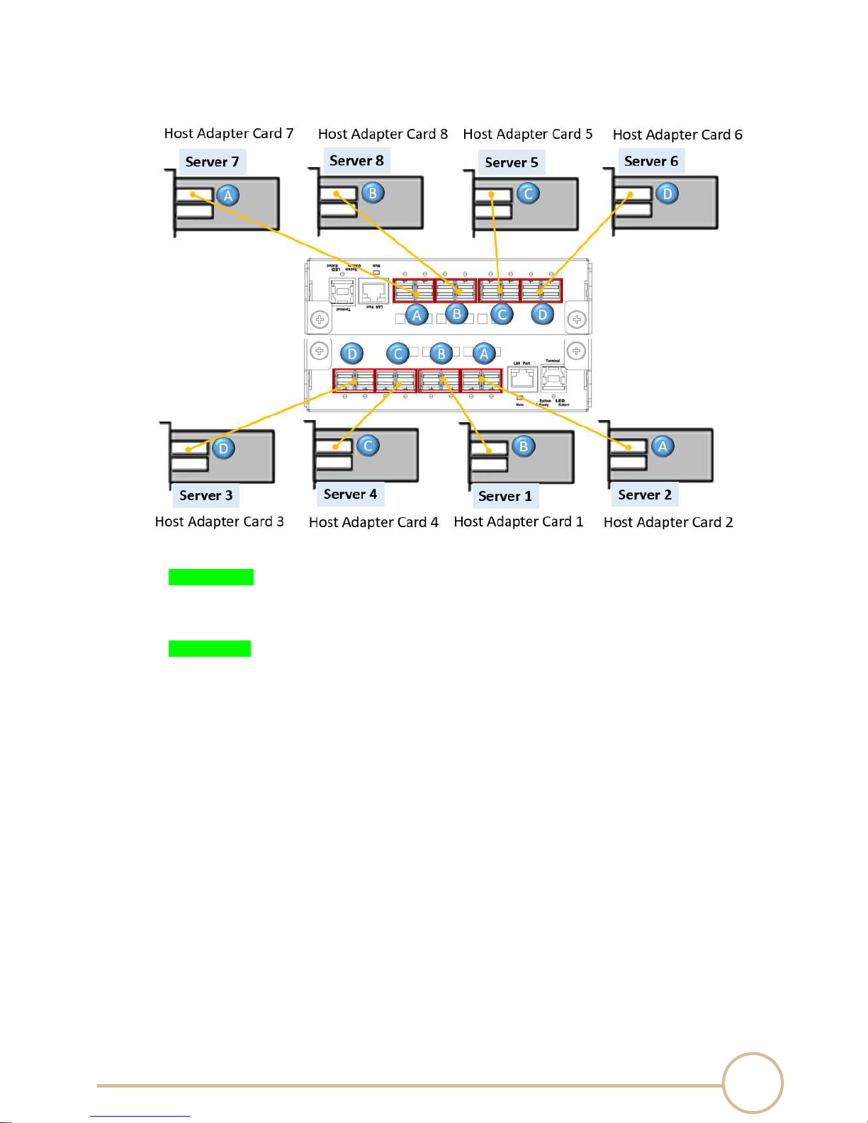
3. Mode 3: Four VR mode, x16 configuration
Bandwidth:
PCIe switch board A: PCIe Gen3 x32 256GT/s
PCIe switch board B: PCIe Gen3 x32 256GT/s
NVMe SSD:
Server 1 can assess NVMe SSDs in Slot 1 to 3.
Server 2 can assess NVMe SSDs in Slot 4 to 6.
Server 3 can assess NVMe SSDs in Slot 7 to 9.
Server 4 can assess NVMe SSDs in Slot 10 to 12.
Server 5 can assess NVMe SSDs in Slot 13 to 15.
Server 6 can assess NVMe SSDs in Slot 16 to 18.
Server 7 can assess NVMe SSDs in Slot 19 to 21.
Server 8 can assess NVMe SSDs in Slot 22 to 24.
9
Function
Description
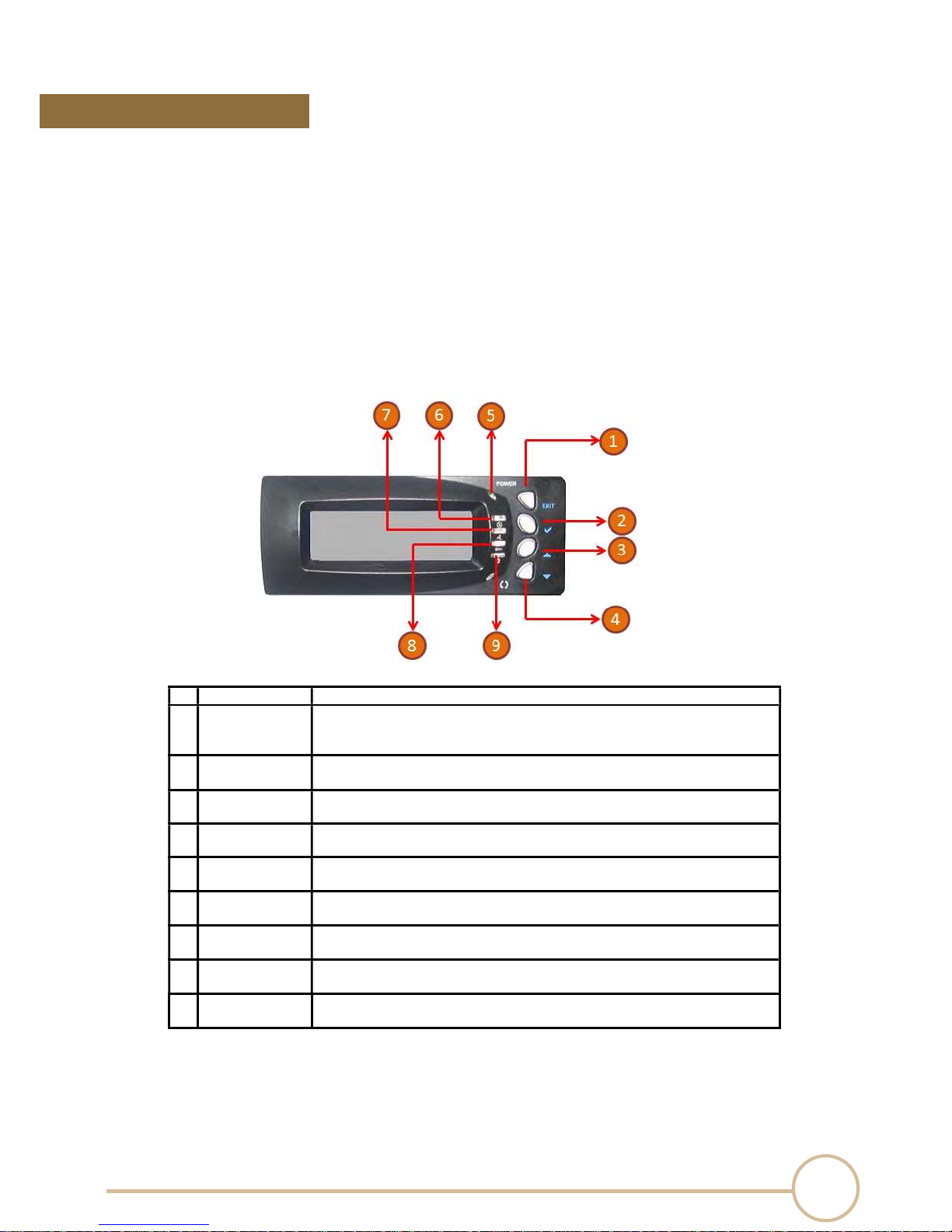
Enter Key
▲
4 Down Key
▼
Use to scroll the cursor Downward / Leftward
6 PSU
status
Normal
– No light
9 Power
status
OFF –
No light
SERIAL CABLES NVMe JBOF User’s Manual
LCD configurations
3.
This technical manual provides, in quick reference form, procedures that use the built-in LCD panel
to configure and operate the controller. The LCD provides a system of screens with areas for
information, status indication, and menus. The LCD screen displays up to two lines at a time of
menu items or other information.
3.1 Function key definitions
The four function keys at the front panel of the button perform the following functions:
1 Exit/Mute Key 1. Power Onpress 1s to power on the system.
2. MutePress 1s to disable the beeping of system failure events.
3. ReturnPress to previous screen.
2
✔
3 Up Key
5 Stanby status
LED
LED
7 FAN status
LED
8 Temp status
LED
Submit selected icon function
(Confirm a selected item)
Use to scroll the cursor Upward / Rightward
OFF – No light
ON – Blue
Failure – Red
Normal – No light
Failure – Red
Normal – No light
Failure – Red
LED
ON – Green

10
Step1: Enter password
SERIAL CABLES NVMe JBOF User’s Manual
3.2 Function key definitions
The main menu appears on the LCD screen as shown below:
Use the UP/DOWN to move left and right and highlight a menu item. Press ENT to select the
highlighted item. Press the UP/DOWN to browse the selection. Press ESC to return to the
previous screen.
Select an option, related information or submenu items, to display beneath it.
The LCD configuration main menu are:
Functions Description
Fan Info Show system FANs TACH info.
Temp Info Show system temperatures info.
PSU Info
Slot Info Show link width and speed for NVMe slots.
Show system PSU info, including voltage, current, FAN info and
temperature.
Port Info Show link width and speed for ports of PCIe switch board.
Ethernet IP Info Show Ethernet port info of PCIe switch board.
Firmware Upgrade
Firmware Version Show all FW versions, including LCD and PCIe switch boards.
System Power OFF Enter password (default is “00000000”) -> power off
Set Password
Step2: Choose switch board A/B, notify PCIe switch board
upgrade FW.
Step1: Enter old password
Step2: Enter New password
Step3: Verify new password
LCD displays new password been changed
11
SERIAL CABLES NVMe JBOF User’s Manual
4.
CLI
This Command Line Interface (CLI) is provided for you to manage the NVMe controller functions.
The CLI is useful in environments where a graphical user interface (GUI) is not
ANAGER
M
available.
‧
Location of USB
Port
NVMe JBOF enclosure uses the USB port as the serial port interface. Please us e the USB type A
male to Type B male cable to connect switch controller to PC and operation system will detect a
new “
USB-to-Serial COM Port”. Please use this serial port
Note: USB-to-Serial bridge chip is Prolific PL2303, user can download Windows, Mac OS X driver
from http://www.prolific.com.tw
USB port location:
‧
Establishing the Connection for the USB
Port
to configure the switch
controller.
The CLI function can be done by using an ANSI/VT-100 compatible terminal emulation program. You
must complete the appropriate installation procedure before proceeding with the CLI function.
Whichever terminal emulation program is used must support the XMODEM file transfer
protocol.

12
SERIAL CABLES NVMe JBOF User’s Manual
4.1 Start-up VT100 Screen
By connecting a VT100 compatible terminal, or a PC operating in an equivalent terminal emulation
mode, all CLI administration functions can be exercised from the VT100 terminal.
There are a wide variety of Terminal Emulation packages, but for the most part they should be very
similar. The following setup procedure is an example setup VT100 Terminal in Windows 7 system
using Tera Term 4.83 (a VT100 Terminal Emulation program and it’s an open-source, free, software
implemented, Terminal Emulator program).
Note: If you have encountered an issue with newer version of Tera Term, we recommend
you to use old version Tera Term. (4.83 or older version)
Step 1. Install and launch Tera Term application (or Hyper Terminal requires version 3.0 or
higher).

13
SERIAL CABLES NVMe JBOF User’s Manual
Step 2: To ensure proper communications between NVMe JBOF controller and the VT100 Terminal
emulation, please configure the VT100 Terminal emulation settings to the values shown below:
For “Port”, select COM3 in this example. (Depend on which COM port used on Host)
For “Baud rate”, select 115200.
For “Data”, select 8 bit. For “Parity”, select none.
For “Stop”, select 1 bit. For “Flow control”, select: none.
Click OK when you have finished your selections.

14
SERIAL CABLES NVMe JBOF User’s Manual
Step 3: Configure Terminal emulation type, please configure the VT100 Terminal emulation
settings to the values shown below:
For “Terminal ID”, select VT100.
Click OK when you have finished your selections.

15
SERIAL CABLES NVMe JBOF User’s Manual
Step 4: Setup is complete. Type “ver” [Enter] to check terminal, screen will print information
shown below:

16
SERIAL CABLES NVMe JBOF User’s Manual
4.3 CLI Command
This section provides detailed information about NVMe JBOF enclosure’s CLI function. All the
commands please type in lower case.
• help Command
This command provides an line-by-line table of contents, providing brief descriptions of the supported
command groups and built-in commands.
You can use “help” to get detail information about the CLI commands summary.
Syntax
JBOF>help[Enter]
Example:
There are 4 command groups, if user want to check CLI commands in one of any groups.
Example:
JBOF>help netif [Enter]

17
SERIAL CABLES NVMe JBOF User’s Manual

18
SERIAL CABLES NVMe JBOF User’s Manual
• netinfo Command
This command provides detailed information of the Ethernet interface.
Syntax
JBOF>netinfo[Enter]
Example:
NBNS – NetBIOS Name Service protocol
IPv4 Address – IP address of Interface
Mask – Netmask mask
Gateway – Default Gateway
DNS – IP address of DNS
MAC Address – A unique MAC address of Interface
default IP address On/Off
dhcp function enable/disable
Link status of Interface

19
SERIAL CABLES NVMe JBOF User’s Manual
• setip Command
Set IP address and Subnet mask of the Ethernet interface.
Syntax
Usage: setip <interface> <ipv4/6 address> <ipv4mask/ipv6 prefix len>
Example: Change Ethernet port IP address of interface eth0 to 192.168.0.8
setip eth0 192.168.0.8 255.255.255.0

20
SERIAL CABLES NVMe JBOF User’s Manual
• setgw Command
Set gateway IP address
Syntax
Usage: setgw <interface> <ipv4/6 address> <validTime>
Example: Change gateway IP address of interface eth0 to 192.168.0.1
setgw eth0 192.168.0.1

21
SERIAL CABLES NVMe JBOF User’s Manual
• setdns Command
Set DNS IP address.
Syntax
Usage: setdns <interface> <x.x.x.x>
Example: Change DNS server IP address of interface eth0 to 192.168.0.253
setdns eth0 192.168.0.253

22
SERIAL CABLES NVMe JBOF User’s Manual
• dhcp Command
DHCP client command.
Syntax
Usage: dhcp <interface> <on/off/renew/request/info>
Example: dhcp eth0 on
Example: dhcp eth0 off

23
SERIAL CABLES NVMe JBOF User’s Manual
• setbios Command
Set host's NetBIOS name.
Syntax
Usage: setbios <interface> <string>
Example:
setbios eth0 JBOF_01

24
SERIAL CABLES NVMe JBOF User’s Manual
• if Command
Ethernet interface enable/disable.
Syntax
Usage: if <interface> <down/up>
Example: if eth0 down
Example: if eth0 up

25
SERIAL CABLES NVMe JBOF User’s Manual
• macinfo Command
Check MAC statistics.
Syntax
Usage: macinfo
Example:
macinfo

26
SERIAL CABLES NVMe JBOF User’s Manual
• ping Command
ICMP client ping command.
Syntax
Usage: ping <stop> <if> <name/address> <n> <msDelay>
Example: ping IP address 192.168.31.1 6 times
Ping 192.168.31.1 6

27
SERIAL CABLES NVMe JBOF User’s Manual
• showslot Command
This command is for displaying link speed and link width information of a specific NVMe drive slot.
Syntax
Usage: showslot slot(D)
Example: Show link speed and link width of slot 2, 3
Note: There is one Gen3 x4 NVMe SSD installed in Slot02
present: Yes -> drive presence in slot
No -> no drive presence in slot
speed : 01->Gen1, 02->Gen2, 03->Gen3
width : 00->link down, 02-> x2, 04-> x4

28
SERIAL CABLES NVMe JBOF User’s Manual
• ssdpwr Command
This command is for controling the power of each NVMe drive slot.
Syntax
Usage: ssdpwr slot(D) on/off
slot(D) : slot number shoule be 1 ~ 12
Example: There is one Gen3 x4 NVMe SSD installed in Slot02 and turn off power of Slot02
After turn off power of Slot02, drive presence but link is down (speed 01 width is 00)
Example: Turn on power of Slot02
After turn on power of Slot02, link is back (Gen3 x4)

29
SERIAL CABLES NVMe JBOF User’s Manual
• buz Command
This command is for controlling the buzzer on the switch controller board.
Syntax
Usage: buz on/off
Example: Turn on buzzer
buz on
Example: Turn off buzzer
buz off

30
SERIAL CABLES NVMe JBOF User’s Manual
• pos Command
This command is for showing position information on the switch controller board in system.
Syntax
Usage: pos
Example: Check controller board position

31
SERIAL CABLES NVMe JBOF User’s Manual
• showport Command
This command is for displaying link speed and link width information of all NVMe drive slots.
Syntax
Usage: showport <-t –b>
-t: Top controller board, -b: Bottom controller board
Example: Show link speed and link width of bottom controller board
showport -b

32
SERIAL CABLES NVMe JBOF User’s Manual
• setmode Command
This command is for setting configuration of the switch controller board.
Syntax
Usage: setmode mode(D) option(D)
mode 1 ~ 3
1 : Base mode
2 : 2 Virtual switch
3 : 4 Virtual switch
option 0 ~ 2
0 : read tracking disable, lane reverse enable, SRIS disable
1 : read tracking enable, lane reverse disable, SRIS disable
2 : read tracking disable, lane reverse enable, SRIS enable
Example 1: select mode 1 with read tracking disable, lane reverse enable, SRIS disable

33
SERIAL CABLES NVMe JBOF User’s Manual
• showmode Command
This command is for showing the configuration of each switch controller board in the system.
Syntax
Usage: showmode
Example: Show mode information of switch controller board in system (TOP and BOTTOM)
showmode

34
SERIAL CABLES NVMe JBOF User’s Manual
• ver Command
This command is for showing the microcontroller firmware version of the switch controller board.
Syntax
Usage: ver
Example:
ver

35
SERIAL CABLES NVMe JBOF User’s Manual
• lsd Command
This command is for showing environmental conditions information of the NVMe JBOF system.
Syntax
Usage: lsd
Example: lsd
(Note: During test, PSU2 and System Fan 1,2 are not installed)

36
SERIAL CABLES NVMe JBOF User’s Manual
• showfan Command
This command is for showing the fan speed information on the switch controller board.
Syntax
Usage: showfan
Example: showfan

37
SERIAL CABLES NVMe JBOF User’s Manual
• showtemp Command
This command is for showing the internal temperature of PCIe switch chip.
Syntax
Usage: showtemp
Example: showtemp

38
SERIAL CABLES NVMe JBOF User’s Manual
5. Firmware Upgrade
Enter the firmware upgrade mode
There are two ways to enter the firmware upgrade mode
From LCD panel, select upgrade firmware option Or
Before power on system, press and hold mute button ( -> near LAN port ) then power on system
If enter firmware upgrade mode success, user can check “System healthy LED ” is blinking
(Green/Red)

39
SERIAL CABLES NVMe JBOF User’s Manual
Launch the firmware upgrade application and setting
After launch application, select the “Com Port” used to upgrade firmware and the baud rate is 115200
then click connect
Check the message to make sure device is connected.

40
SERIAL CABLES NVMe JBOF User’s Manual
Load firmware file
Click “Load Hex File” button to select firmware file

41
SERIAL CABLES NVMe JBOF User’s Manual
Begin to upgrade firmware process
After load firmware file, click “Erase-Program-Verify” button to start upgrade process.

42
SERIAL CABLES NVMe JBOF User’s Manual
Disconnect serial port and power cycle the system

43
Minor changes, corrections
.
SERIAL CABLES NVMe JBOF User’s Manual
History
Publication History
Revision Date
1.0 2017/01/09 Original (Based on FW version 0.9.2S)
1.1 2017/08/31 Based on FW version 1.0.8A
1.2 2018/3/15 Add pictures and descriptions for accessories in package
Description of Changes
Refine CLI command portion.
 Loading...