

Page 1

Page 1 of 79User Manual NV
R
Serenity
Network Video Recorder
(8 & 16 channel units)
User Manual
Version 7.0
Copyright © 2005
Cybasec Ltd.
All Rights Reserved
Confidential:
Unauthorized disclosure is prohibited. Failure to observe Cybasec’s policies regarding proprietary information can r esult in legal action, and
The information contained within this document is Proprietary an d Confidential and subject to non-disclosure agreement.
12/7/2005https://serenity-support.gviss.com/html/doc/UserManNVR.htm
Page 2

Page 2 of 79User Manual NV
R
subject you and/or third parties to legal liability.
Quick-Search Function Table
No.
001
management
002
101
102
103
104
105
106
201 Display mode
202
203 Alarm linkage
204
205
801
Password
management
Hard disk
installation
Video recording
Video recording
Recording
parameter
Playback mode
Backup editing
PTZ control
Privacy mask
View Tampering
Exceptions
Broad band
Name
User
mode
policy
dialup
Type
Safety
function
Safety
function
Hard disk
video
recording
Hard disk
video
recording
Hard disk
video
recording
Hard disk
video
recording
Hard disk
video
recording
Hard disk
video
recording
Local
monitoring
Local
monitoring
Local
monitoring
Local
monitoring
Local
monitoring
Network
function
Multi-stage authorization management: one
system administrator, one super user and user.
Password verification, operation exceeding the
authority will be warned and recorded in log.
The equipment can support max. 8 IDE hard
disks inside, max capacity for each IDE hard
disk is 250GB.
Scheduled record, manually record, triggered
record by command, motion detection, alarm
record, motion detection & alarm record, motion
detection| alarm record
Circular coverage of recording or non-circular
recording (hard disc full alarm)
Bit rate and frame rate is adjustable, code flow
value can be set, or picture quality can be set
(adjustable in 6 grades, variable bit rate)
Support timed playback (precision in second),
with playback modes of fast play, slow play,
pause and play frame by frame etc.
Full backup and segment editing of recorded
video file
Support monitor and VGA local display, display
modes include 1/4/10/16 pictures, with manual
or automatic switch-over (the cycle can be set)
Speed variation, slanting motion, preset position
and cruise
Switch volume, exception, motion detection
linkage output
Coverage on sensible spot in picture, The
response of regional coverage warning etc. is
provided when lens is maliciously blocked.
Trigger alarm output when HDD or network has
exceptions.
Link to Internet by PPPoE protocol broad band
dialup
Description
Page
24
14
62
17, 36
36
36
18
21
26
16, 41
37
30, 32
44
53
12/7/2005https://serenity-support.gviss.com/html/doc/UserManNVR.htm
Page 3

Page 3 of 79User Manual NV
R
802
803
804
805
806
807
808
809
810
811
812
813
901
902
903
904
Real time
Web
OSD
Talk
preview
Remote Control
Command
Network alarm Network
Remote PTZ
control
Remote setting Network
Remote
recording
Remote
playback
Remote
download
Remote
maintenance
Transparent
channel
Narrow band
transfer
LOGO
View Log
Network
function
Network
function
function
Network
function
function
Network
function
Network
function
Network
function
Network
function
Network
function
Network
function
Network
function
Auxiliary
function
Auxiliary
function
Auxiliary
function
Auxiliary
function
Compressed code flow transferred by TCP,
UDP, RTP and broadcasting modes etc.
Remote control the front panel to search and
playback the file, etc.
Alarm signal is transferred upload through net.
Remote control of PTZ, set and call of pre-set
position
Set the NVR parameters through network.
Management host can real-time record
compressed code flow through network.
Management host can playback the files
recorded in NVR through network.
Management host can edit and down load the
files on hard disk through network.
Remote upgrading through network to realize
remote maintenance.
Both RS-232 serial port and RS-485 interface
support network transparent channel connection,
management host can control cascade devices
through transparent channel of NVR.
Using browser to access the NVR.
Access the NVR through PSTN.
“
on added OSD, multi-mode displays, added
position can be adjusted
The length of overlapped channel name is 32
characters, multi-mode displays, added position
can be adjusted
Operation log, alarm log, exception log
Two-way voice talk, one-way voice broadcasting
year-month-day-week-hour-minute-second”
40
44
54
28
30
47
*
*
*
*
*
*
*
*
*
*
12/7/2005https://serenity-support.gviss.com/html/doc/UserManNVR.htm
Page 4

N
Page 4 of 79User Manual NV
R
CONTENTS
User Manual.............................................................................................................. 1
Quick-Search Function Table...................................................................................... 2
Operating Instructions........................................................................................................ 6
Important Note.......................................................................................................... 6
Front Panel Description.............................................................................................. 6
Remote Control Operation.......................................................................................... 8
Menu Description..................................................................................................... 10
Basic Operation Guide..................................................................................................... 15
Power on................................................................................................................. 15
Preview................................................................................................................... 15
Username and password........................................................................................... 16
PTZ Control............................................................................................................ 17
Manual Record........................................................................................................ 18
Playback................................................................................................................. 19
Backup a Recorded File............................................................................................ 22
Voice over Internet................................................................................................... 24
Shut Down.............................................................................................................. 24
Administrator Operating Guide......................................................................................... 25
About Administrator and the Password....................................................................... 25
Modify Unit Name and Device ID............................................................................. 26
Video standard......................................................................................................... 27
Local monitor - Preview properties............................................................................ 27
Time Zone and DST................................................................................................. 28
System Time............................................................................................................ 29
Camera Name.......................................................................................................... 30
Video Parameters..................................................................................................... 31
Privacy Mask Area................................................................................................... 33
Tampering Setup...................................................................................................... 34
Signal Loss Alarm Setup........................................................................................... 35
Motion Detection Setup............................................................................................ 36
Recording Channel Configuration............................................................................... 38
Alarm Parameters Setup........................................................................................... 40
Network parameters................................................................................................. 43
PTZ........................................................................................................................ 44
Serial port setup....................................................................................................... 46
Exceptions............................................................................................................... 47
Transaction Information............................................................................................ 47
Utilities.................................................................................................................... 50
etwork Operation.......................................................................................................... 55
PPPoE dialup.......................................................................................................... 55
Create Connection by Using PPPoE................................................................... 55
12/7/2005https://serenity-support.gviss.com/html/doc/UserManNVR.htm
Page 5

Page 5 of 79User Manual NV
R
Access through Client software when using PPPoE.............................................. 55
PPP(Modem) passive dialup..................................................................................... 56
NVR-end setup................................................................................................. 56
PC-end setup.................................................................................................... 57
Serial port directly connected..................................................................................... 60
Server-end setup............................................................................................... 60
PC-end setup.................................................................................................... 61
Upgrading NVR Firmware................................................................................................ 63
Installation Introduction................................................................................................... 63
Install Hard Disk...................................................................................................... 63
Back Panel Introduction............................................................................................ 64
Alarm input/output connection method....................................................................... 64
RS-485 connect cable made method.......................................................................... 65
UTP network connect cable made method.................................................................. 66
RS-232 connect cable............................................................................................... 67
Specifications........................................................................................................... 70
Frequently Asked Questions............................................................................................. 71
Product Service............................................................................................................... 73
Appendix C
Appendix D
Appendix F..................................................................................................................... 76
Contact Information.................................................................................. 74
Default Settings....................................................................................... 75
Camera Status Lights on Screen....................................................................................... 76
12/7/2005https://serenity-support.gviss.com/html/doc/UserManNVR.htm
Page 6
Page 6 of 79User Manual NV
R
Operating Instructions
Important Note
This manual describes the operation of the NVR unit.
However the recommended method of configuring and administering the NVR unit is through the Serenity NetAdmin
software ap plication supplied by GVI Security Inc with each NVR unit. The NetAdmin software is browser-based ,
and is a more flexible, powerful, and user-friendly interface for manipulating and monitoring the functions of the
NVR.
The N VR front panel buttons, or the accompanying remote control unit, should be used when the NVR user
does not have access to a PC connected to the NVR.
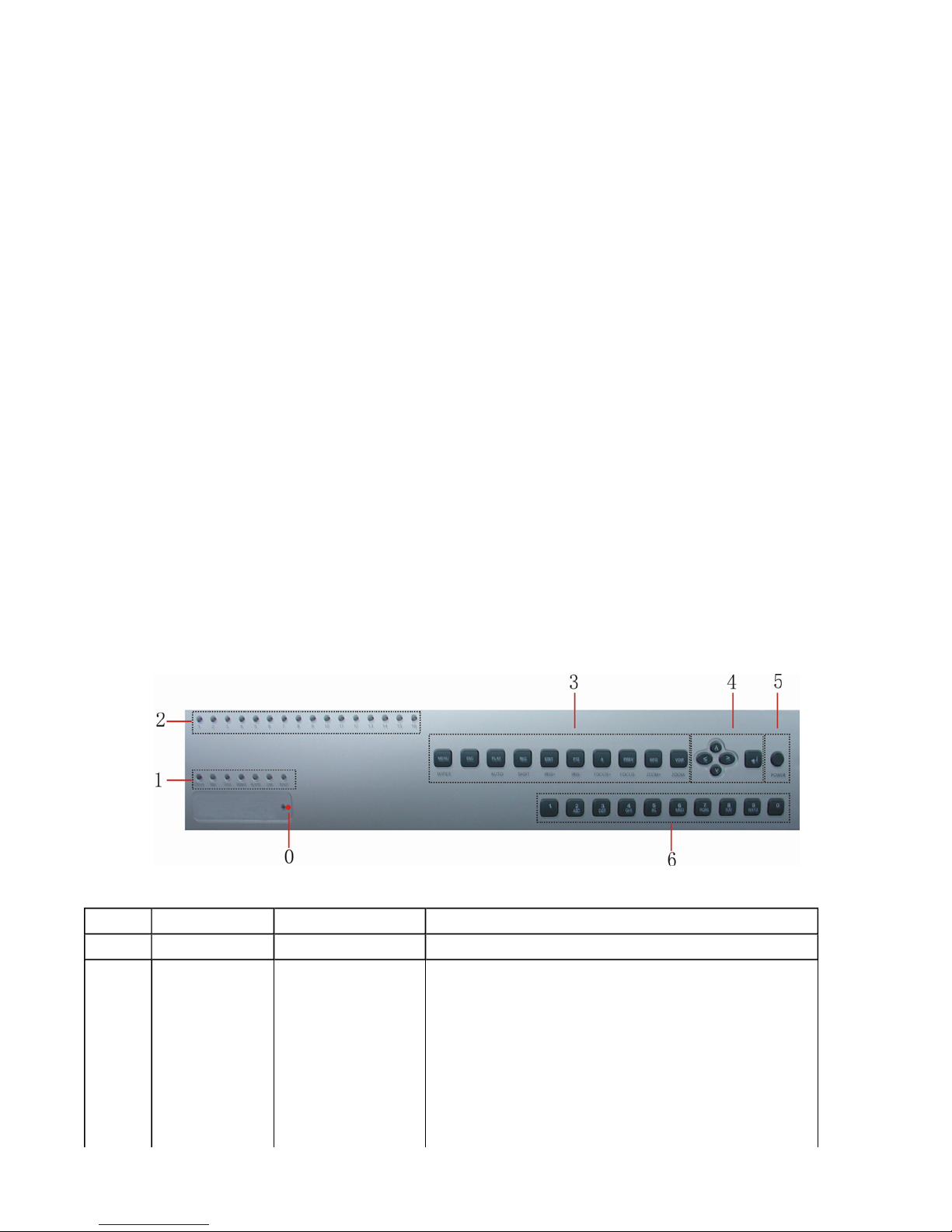
Front Panel Description
No.
0
1
Name
STATUS
HDD
TX/RX
MODEM
ALARM
Type
Status light
Status light
Status light
Status light
Status light
Description
Infrared receiver, product brand.
Under remote control status (green).
Hard disk operation status.
Whether the network is transmitting/receiving data or
not
Reserved
On (red) when any dry contact alarm is in alarm.
Network linking status.
12/7/2005https://serenity-support.gviss.com/html/doc/UserManNVR.htm
Page 7

Page 7 of 79User Manual NV
R
LINK
READY
2
3
4
5
6
1-16
Main Menu
ESC
Playback
Record
Edit
PTZ control
Input Method
Multi-picture
System
information
Voice Comm.
Direction key
Confirmation
key
Power switch
Number key
Status light
Status light
Status lights
Function key
Control key
Function key
Function key
Control key
Function key
Control key
Control key
Function key
Function key
Control key
Control key
Control key
Input key
NVR is ready.
Channel 1-16 status indication, “Green” indicates
recording, “red” indicates network transmission is
occurring, “orange” indicates both recording and
network transfer.
【
MENU】key. Switch from Preview display to Menu
display.
【
ESC】key. Cancel the current operation, return to the
previous menu.
【
PLAY】key. Commence Local playback
【REC】key. Initiate video recording manually
【
EDIT】key. Edit a configuration. Can also delete the
characters in front of cursor.
【
PTZ】key. Enter into PTZ control mode.
【
#/*/ $】key. Switch between input character types
(numeral, letter or symbol).
【
PREV】key. Selects Preview display if in Menu
display or selects single, quad, 9 or 16 view Preview
display.
【INFO】key. Check NVR system information
【VOIP】key. Reserved for future use
Menu selection (
(【Ç】,【È】keys) set selected menu item . The keys
are also used for direction control when PTZ Camera
control is active.
【Enter】key. For operation confirmation
Device switch, with electrical power indication. “Green”
indicates “On”; “Red” indicates “Standby” and no light
indication indicates that the rear power switch is off or
the unit is not receiving mains power.
Numeral keys and English letter keys are combined for
input of numerals, capital & small English letters or
symbols.
【Å】,【Æ】
keys), select menu item.
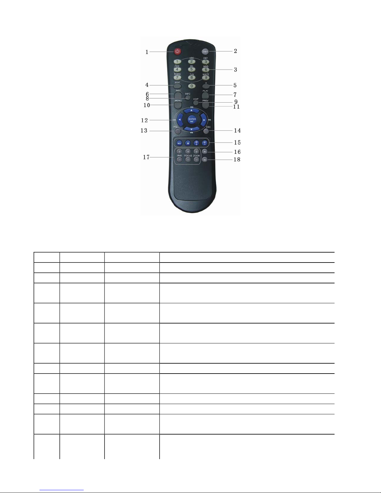
Remote Control Operation
12/7/2005https://serenity-support.gviss.com/html/doc/UserManNVR.htm
Page 8
Page 8 of 79User Manual NV
R
No. Name
1
Switch
2
Device
3
Number key Input key
4
Edit
5
Input Type
Selection
6
Video
recording
7
Video play
8
System
information
9
Talk
10
11
12
Main menu
Preview
Display
Direction key Control key
Type
Control key
Control key
Control key
Control key
Function key
Function key
Function key
Function key
Function key
Control key
Description
Power On/Standby switch for NVR.
Selection of NVR device number
Input keys for English capital & small letters, numbers or
symbols
Enter edit status. Can also be used to delete the character in
front of the current cursor position.
Select Input type (number, English letters or symbols)
Manually initiate video recording
Manually initiate Local playback
Displays NVR system information
Start voice dialogue (Reserved for future use)
Switch from Preview Display to Menu Display
Selects Preview display if unit is in Menu display. Also used to
select single, quad x9 and x16 Preview video display.
Menu selection (【Å】,【Æ】keys), select menu item.
【Ç】,【È】
(
keys) set selected menu item . The keys are also
12/7/2005https://serenity-support.gviss.com/html/doc/UserManNVR.htm
Page 9

r
Page 9 of 79User Manual NV
R
used for direction control when PTZ Camera control is active.
13
14
15
16
17
18
PTZ
ESC
Playback
F1
PTZ control
F2
Function key
Control key
Control keys
Control key
Select PTZ control
Cancel the current operation, return to the previous menu
Play, pause , stop, fast forward or fast reverse playback
Reserved
Open or Close Iris, Adjust focus or zoom in or out when using
PTZ control
Reserved
Inserting batteries into remote control
Open the battery compartment cover of remote control unit.
1.
Insert 2 AAA size alkaline batteries ensuring polarity is as indicated.
2.
Close the cover.
3.
Start using remote control
Press 【DEV】 on the remote control, then input the “Device ID” for the unit to be controlled (default is “01”).
The actual device ID can be changed in the “Display” menu. Next press 【Enter】 on the remote control. If the
“STATUS” LED on the device panel now turns green, it indicates that the remote control can now be used fo
operating the selected device.
Disabling Remote Control
Press【DEV】. The “STATUS” light on the device panel will extinguish and the remote control is now disabled
for control of that device.
Using remote control to shut down
Press 【POWER】on the remote control for at least 3 seconds, input password and confirm as required to
shutdown the NVR.
If remote control does not function normally
z
Check battery polarity
z
Check if batteries need replacing
z
Check there are no physical obstructions between the remote control receiver on the equipment front panel and the
remote control.
z
Ensure there are no strong fluorescence light sources nearby
Note: If remote is still inoperative, change the remote control unit. If that does not resolve the issue contact GVI
12/7/2005https://serenity-support.gviss.com/html/doc/UserManNVR.htm
Page 10

Page 10 of 79User Manual NV
R
customer support – serenity-support.gviss.com.
12/7/2005https://serenity-support.gviss.com/html/doc/UserManNVR.htm
Page 11

Menu Description
R
Menu Guide
Page 11 of 79User Manual NV
Main Menu
Display
Setup
Image
Setup
Video Standard
Brightness
Menu Transparency
Unit Name
Device ID
Require Password
Screen Save Time
VGA Resolution
Time Zone/DST
Date
Time
Channel name modify, Position adjust
Adjust brightness / contrast / hue / saturation
OSD display mode, adjust OSD position
Privacy mask area setup
View tampering area setup and alarm response policy:
On Screen Warning
Signal loss response policy:
Motion detection level and area setup
Motion detection alarm response policy:
Audible Warning
Upload to Center
Trigger alarm output
On Screen Warning
Audible Warning
Upload to Center
Trigger alarm output
Trigger record channels
On Screen Warning
Audible Warning
Upload to Center
Trigger alarm output
Function options
Recording
Setup
Choose to overwrite or stop recording when hard disk is
full
Channel recording parameter
12/7/2005https://serenity-support.gviss.com/html/doc/UserManNVR.htm
Page 12

Page 12 of 79User Manual NV
R
Network
Setup
Alarms
Setup
Exceptions
Setup
PostRecord time
Recording schedule
Network relevant parameter
Remote host IP address
PPPoE user’s name and password
Alarm sensor type
Alarm input handle policy
Trigger record channels
Response policy
Trigger Alarm Output
Trigger PTZ linkage
Set alarm input schedule
Set alarm output schedule
Set alarm output delay time
On Screen Warning
Audible Warning
Upload to Center
Trigger alarm output
PTZ
Setup
Setup
Setup
User
Setup
Setup
RS-232
Preview
Transaction
PTZ relevant parameter
Set preset points
Set sequence
Set cruise
RS232 relevant parameter
PPP mode
Serial port direct connect
Transparent channel
Preview mode
Picture switch time
Enable audio preview option
Channel display layout
Add, delete user
Password setup, modification
User rights setup
User physical address setup
Input method
ATM IP address
ATM type
Other ATM information
Restore to default setting
Upgrade
12/7/2005https://serenity-support.gviss.com/html/doc/UserManNVR.htm
Page 13
r
Page 13 of 79User Manual NV
R
Setup
Utilities
Initial Setup of the NVR - general
Check hard disk status and format hard disk
Clear alarm output
Reboot the device
Shut down
View log
Check system information
There are 3 methods of initially setting up the NVR by using the front panel controls, the Remote Control Unit or the
Administrative menus available via the Network Player software module. For initial setup it is strongly recommended
the Administrative menus available via the Network Player software module be used. Detailed descriptions on thei
usage are contained in the Network Player Operations Manual.
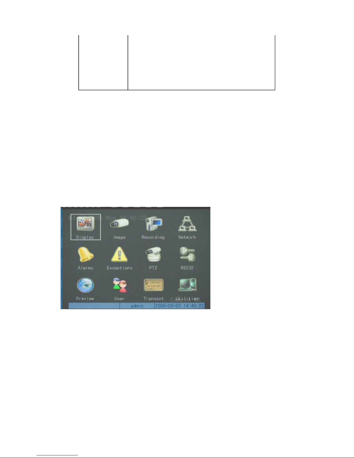
Menu Operation - general
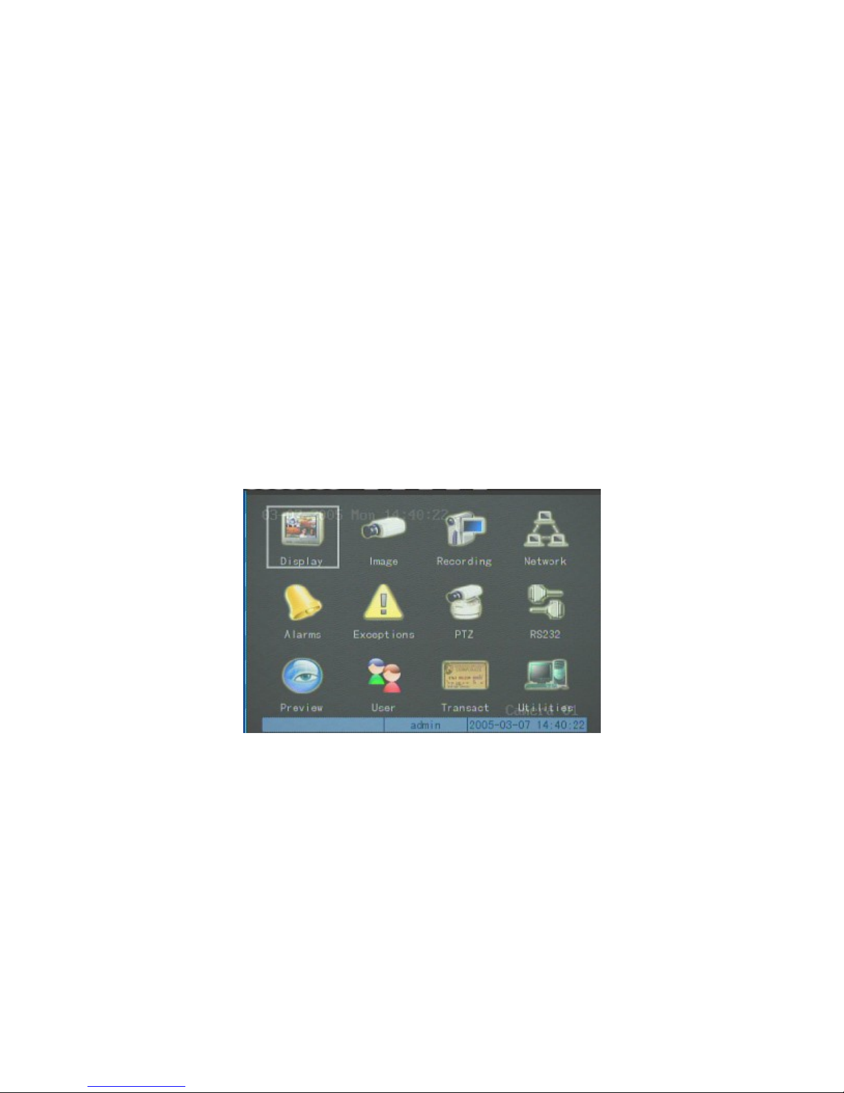
There are typically three menu levels. The first level menu, the main menu, is a graphic icon interface as shown
1.
below This consists of 12 icons which when selected give access to the respective second level menu for that
selection.
Note the rectangular “Activity Frame” which outlines the active icon on the menu screen. The “Activity Frame”
can be moved using the 【Æ】and【Å】keys, and the respective sub-menu (the second level menu) for the selected
main menu item can be entered by pressing 【Enter】when the activity frame is shown around that menu icon. An
example of a second level menu is shown below:
12/7/2005https://serenity-support.gviss.com/html/doc/UserManNVR.htm
Page 14
b
Page 14 of 79User Manual NV
R
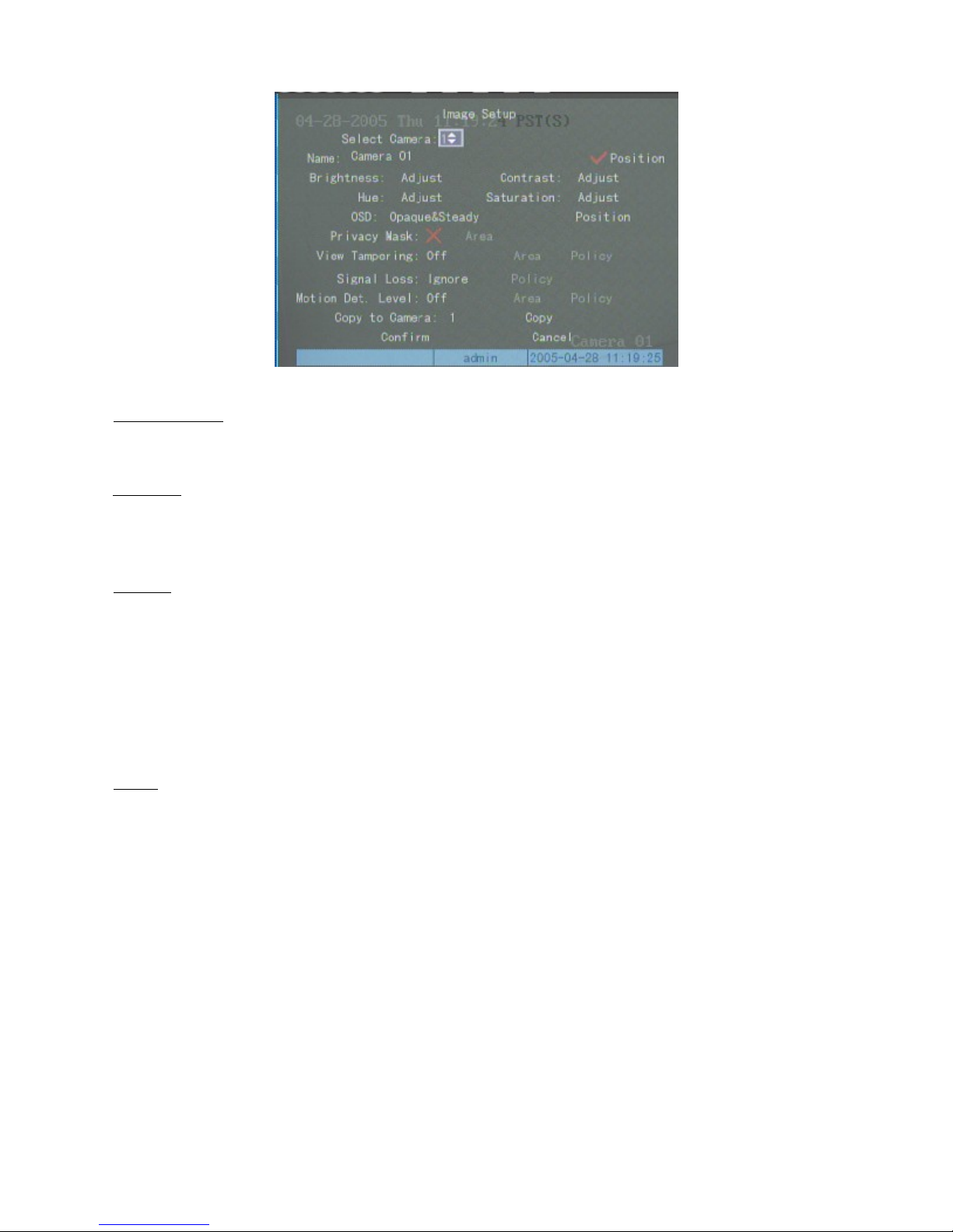
Secondary menus may contain Selection Frames, List Frames, Edit Boxes or action button(s).
Selection Frame: This provides 2 options,
2.
feature is currently inactive,use 【Edit】or【Enter
List frame: This provides multiple options. One of these options can be selected from the available list. Select the
3.
“9”
indicates this feature is currently active,
】
to toggle between Active & inactive.
“×”
indicates this
required option using 【↑】 and 【↓】. In the example shown, the “Select Camera” is a list frame for the
user to select one camera from a list containing 1 to 16;, the defaulted is “1”.
4.
Edit box: This provides a rectangular frame for inputting characters, Edit status can be entered into by pressing
【Edit】. The following operations are available in edit mode:
a)
The character type to be input can be selected using the ”*/#/$” key. Numeric, capital & small English letters and
symbols are available.
The Cursor can be moved using the 【Æ】 and 【Å】Keys.
b)
The character in front of cursor can be deleted by pressing【Edit】.
c)
d)
Editing status can be exited by pressing 【Enter】or【ESC】.
5.
Button: for execution of a specific function or selection of the next menu. For example, the “Confirm” button
executes the functions of data saving and returning to the previous menu. Pressing the “Adjust”
utton selects
the next lower sub-menu. Buttons that are “grayed out” indicate that the control items of that button are
currently invalid and cannot be activated.
12/7/2005https://serenity-support.gviss.com/html/doc/UserManNVR.htm
Page 15

r
r
p
N
N
t
d
Page 15 of 79User Manual NV
R
Basic Operation Guide
Note: In this user manual, various “Buttons” on NVR front panel are expressed as 【Button Names】, for
example, preview key is expressed as 【PREV】, and also the names are the same as those in the menu interface, fo
example, the confirm button is expressed as “Confirm”.
The descriptions below are for using the front panel buttons or the Remote Control Unit and the menu screens
displayed locally on the VGA or Analogue monitor attached to the NVR. In the text that follows, [<Name>] will
indicate a named button on the remote control or front panel button and “Name” will indicate the name of an on screen
menu item or soft button.
Getting Started
Press [Menu] or “
assword using the remote control or front panel buttons, press “>” then [Enter] or “
menu screen selection. Note if this is an initial setup, choose “
(default). This password can be changed later as described below or in the Administrative menus available via the
etwork Player software module.
”. Select {Username} from displayed list, press “
Menu
to select {Password}and enter you
>”
” to {Confirm} and enter the
Enter
” as the Username and “
admin
” as the password
12345
Power on
ote that applying the incorrect voltage may result in permanent damage to the NVR. Incorrect voltage selection will
not constitute a warranty claim and damage repairs will be chargeable.
Step One: Ensure correct voltage is selected on the Voltage selector switch.
Step Two: Connect electrical power.
Step Three: Turn on the power switch on the back panel of the recorder.
Step Four: When power button illuminates red, Press 【POWER
should change from red to green. This indicates the DVR is now ready for recording or setup & configuration changes.
】
gently. The 【POWER】indicator ligh
Preview
Pressing “Prev” causes the NVR to display the Preview screen with a single image. The single image displaye
can be selected using the numeric keys on the front panel or Remote. For example to select a preview of camera 3 press
“0” then “3”.
To return to the menu display press “Menu”.
12/7/2005https://serenity-support.gviss.com/html/doc/UserManNVR.htm
Page 16
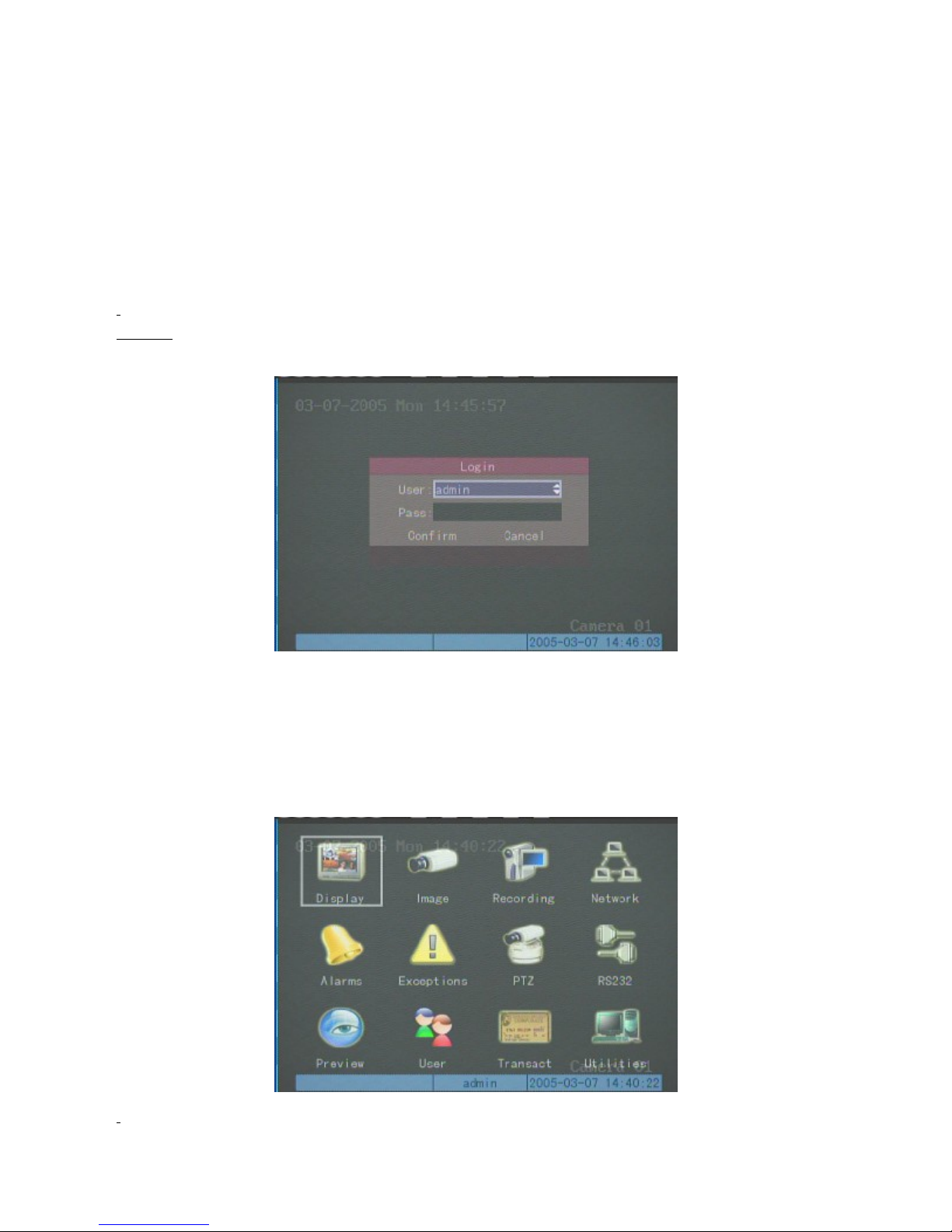
Username and password
p
r
r
R
Page 16 of 79User Manual NV
When the NVR is delivered, there is only one default administrator named “
“
”. This name cannot be modified, but the password can be changed as follows:-
12345
There are 2 other default user accounts. One is “
assword “
11111
You can only modify your own password as follows:
Step one
Press【MENU】. The system will require you to select a Username and password
”.
: Enter the main menu of the NVR.
superuser
” with password “
admin
” and the other is “
88888
” with password set to
” with
user
Use the direction keys 【Ç】,【È】to select your user name; input the password assigned to you by the
administrator in the “password” edit box. Move the cursor to “Confirm ” and press 【Enter】on the front panel o
remote. If there is a warning buzz, you have inserted an invalid current password. You can input the password again,
but the system will exit automatically after three unsuccessful attempts. If this occurs, you should contact you
administrator for assistance.
If the correct combination of username and password are correct the following menu will appear (main menu):
12/7/2005https://serenity-support.gviss.com/html/doc/UserManNVR.htm
Page 17
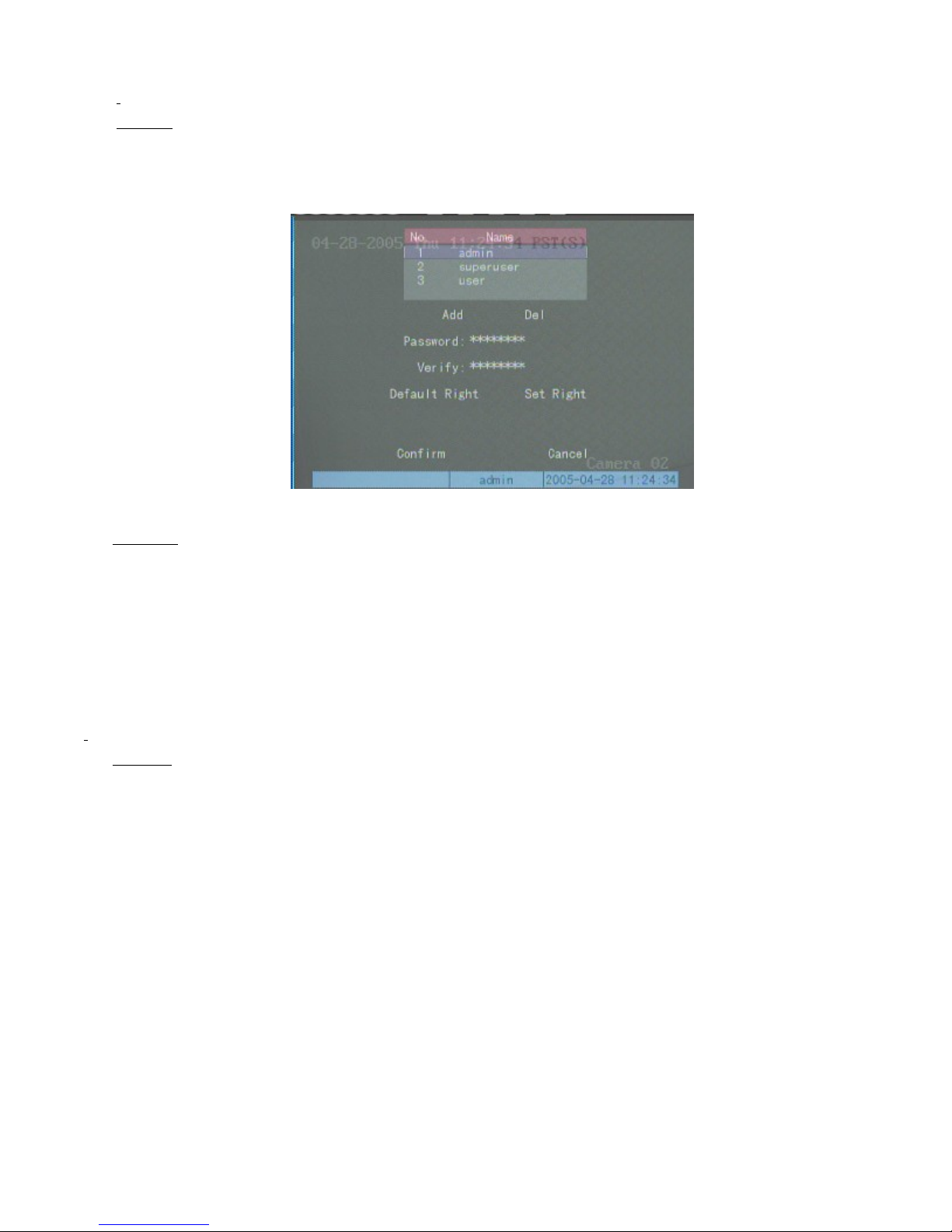
p
r
Page 17 of 79User Manual NV
R
Step two
Use 【Æ】or【Å】 to move the “Activity Frame” to the “User” menu icon. Press 【Enter】 to enter into
: Select “User” menu icon.
user setup sub-menu. .
Step three
Press 【Edit】 to enter into editing status, use numeric keys on front panel or remote to input a new password.
The password can consist of up to 8 numeric characters. Press【Enter】 to exit editing status after inputting the
: Input new password
assword, then press
status.
Step four
Press 【Æ】and move cursor to “Confirm”. The password has been successfully modified if the system returns to
the main menu after 【Enter】is pressed; Step three should be repeated if the system automatically returns the cursor to
the “Password” editing frame.
H Note: The character in front of cursor can be deleted using the 【EDIT】 key in editing status. Use only numerals
only for password characters with no spaces between numerals.
: Password modification is successful.
【Æ】
to move cursor to “Verify” and re-enter new password . Press【Enter
】
to exit editing
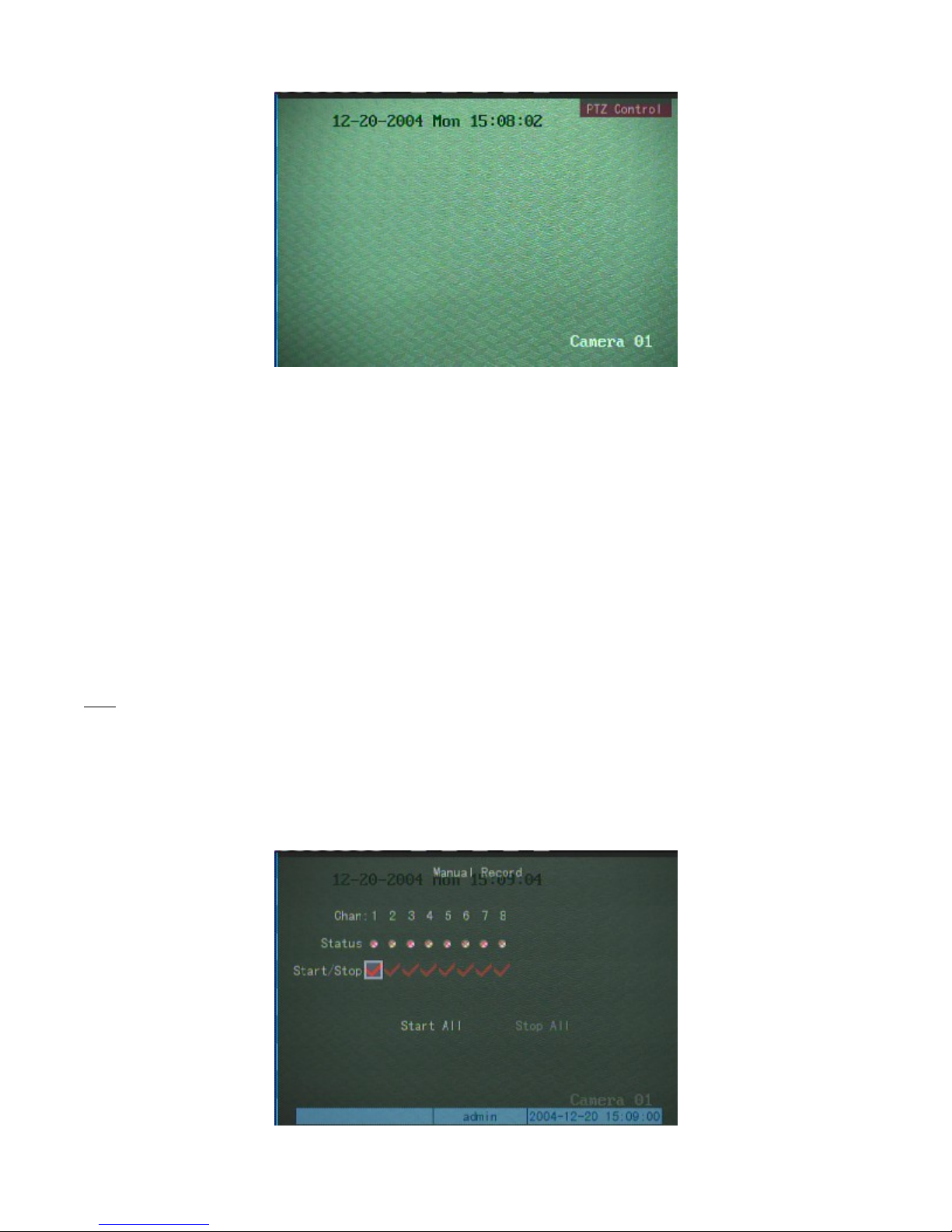
PTZ Control
Press the 【PTZ】 key on the front panel or Remote, choose the username and input the correct password to ente
into the PTZ control sub-menu.
12/7/2005https://serenity-support.gviss.com/html/doc/UserManNVR.htm
Page 18
N
Page 18 of 79User Manual NV
R
The numeric keys on the front panel or the Remote enable selection of the camera to be controlled. For example
to select input “03” press “0” then “3”. After choosing the channel to be controlled, use the Arrow 【↑】,【↓】,
【←】,【→】
【
FOCUS+】,【FOCUS-】,【IRIS+
the controlled camera. To select a preset, press 【REC】then the required numeric keys. For example, press 【REC
then【0】, then 【1】, to select preset 1 on the camera being controlled To exit the PTZ control sub-menu press
【
ESC】.
keys on the front panel or the remote to control the Pan &Tilt Use 【ZOOM+】,【ZOOM-】,
】
and 【IRIS-
】
to control the zoom and lens control functions if supported on
】
Manual Record
ote: Each user has individual “record” operation authority rights. Before recording ensure there is a hard disk on
which to save the data in the device and that you have the authority to do so or contact the NVR administrator.
Press the 【REC
enter into the Manual Record sub-menu.
】
key on the front panel or Remote, select your username and input the correct password to
12/7/2005https://serenity-support.gviss.com/html/doc/UserManNVR.htm
Page 19

r
p
R
Channel and status
All channel numbers are displayed in the channel bar.
Page 19 of 79User Manual NV
The status of a channel is indicated in the “status” list, and there are four indicators, indicates no recording o
network activity on this channel, Green indicates recording, Red indicates network transmission, Orange indicates
simultaneous recording and network transmission.
Start/Stop
channel. . Press the 【Enter or EDIT】key to initiate recording on this channel. The corresponding channel status light
will turn to green or orange, and the corresponding channel status light on the front panel will turn to green or orange;
Pressing the 【Enter】 or 【EDIT】 keys will select “×”and stop the recording of that channel. When stopped,
the corresponding status light turns to or red, and the status light on the front panel will turn off or turn red.
Start All
move the cursor to the “Start All” button and press the 【Enter
channels. The channel status indicator lights on the front panel and the indicators on the Manual Record sub-menu will
all turn to green or orange.
Note: If recording is activated manually, it can only be stopped man ually. If Manual Recording is initiated, the
NVS will record continuously until stopped manually.
Stop All
cursor to the “Stop All” button and press the【Enter】key on the front panel or Remote to stop recording on all
There are two status indicators in the “Start/Stop” list, the “9” and the “×”.
If the status light on the corresponding channel is or red, selecting “9” will initiate recording of that
Selecting
Pushing the “Start All” button activates and starts all channels to be recorded. Use the
Selecting “Stop All” will cause recording to cease on all channels. Use the
“×”
will stop the recording of the corresponding channel if the current status light is green or orange.
【←】
】
key on the front panel to start recording of all
【←】or【→】
【→】
or
key to move the
keys to
channels. Once stopped the status indicators on the Manual Record sub-menu will show or red and the channel
indicator lights on the front panel will turn off or to red.
Note: A channel cannot be stopped manually if it was st arted automatically when the current time causes an
automatically scheduled record session to start.
Playback
Press the 【Play
layback interface.
】
key on the front panel, select your username and input the correct password to enter into the
12/7/2005https://serenity-support.gviss.com/html/doc/UserManNVR.htm
Page 20
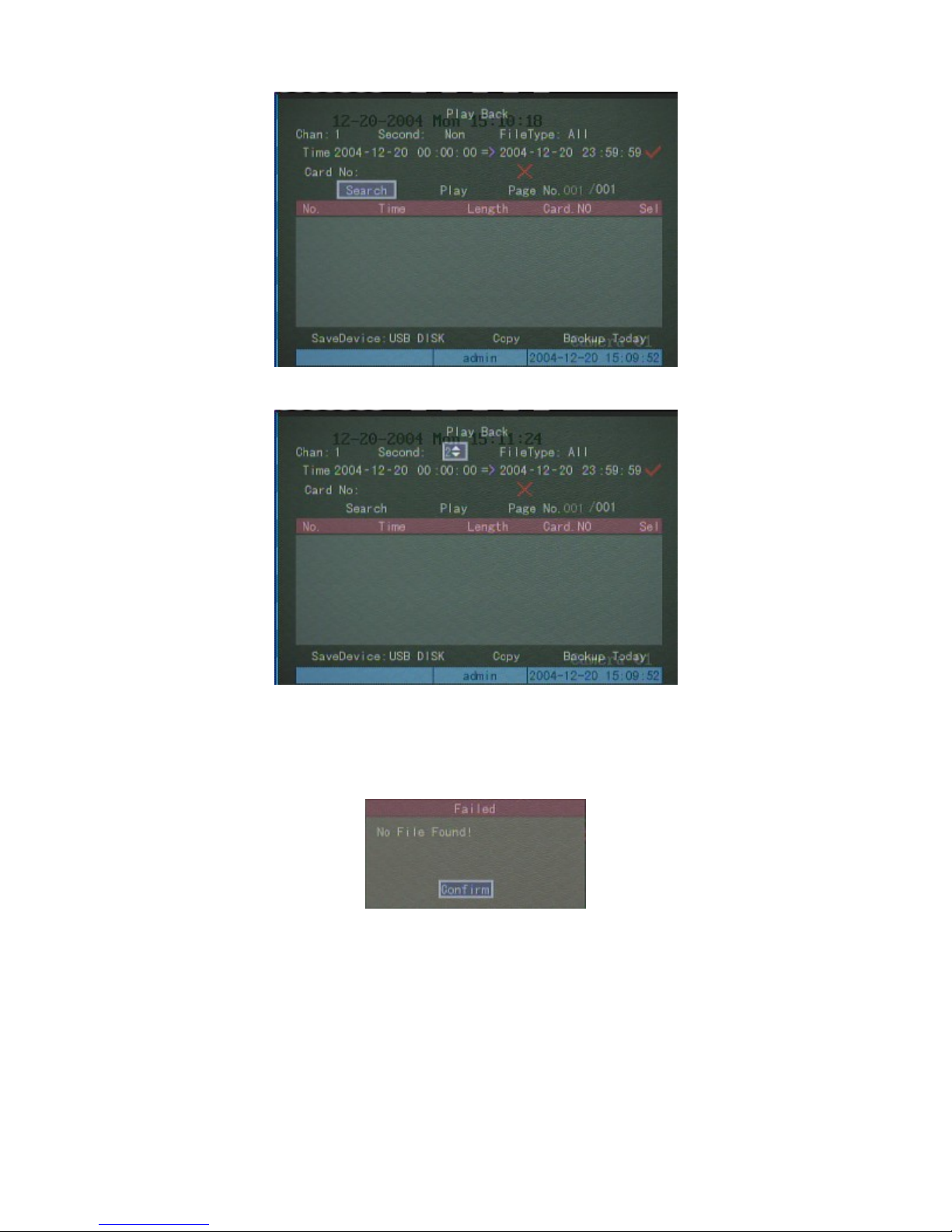
Page 20 of 79User Manual NV
R
One channel playback
Two channels playback
To search recorded files of channel “01” today press the 【Enter】key. If no files exist for today for channel “01”
on the hard disk then the following message will be displayed.
Recorded files can be selected using the following methods:-
Channel No:
Second Channel:
File Type:
【↑】or【↓】keys; the default is “All”.
Time Period:
second); the default is ‘now’ today;
Card Number: This following section refers to an unsupported capability – please ignore it.
Choose a channel using the
use【↑】, 【↓】key – note that the default is “None”.
Select from Time schedule, motion detection, alarm, manual record or all. Make a selection using the
Select an input start time and the stop time using the numeric keys (year month date hour minute
【↑】, 【↓】
keys; the defaulted is “1”.
12/7/2005https://serenity-support.gviss.com/html/doc/UserManNVR.htm
Page 21
f
Page 21 of 79User Manual NV
R
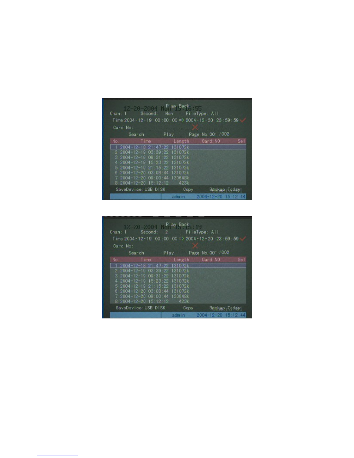
There are three playback options:
Time Search, File Playback:
(default), select “search file”, press the 【Enter】key and a list of available files will be listed (maximum 400). To
scroll through the pages “ Page Selection”. Use the 【↑】,【↓】keys to choose the required file to be played on the
selected page, then press the【Enter】key to play it.
input the start and stop time, enable the time search, ensuring “9” status is selected
One channel playback
Two channels playback
Playback by time:
selected, select “Play ” and press the 【Enter】key to play the recorded files. The start time is precise to the second. I
there are no recorded file(s) in the time period specified a “failed operation” message will appear.
Search Card number, playback file:
Input a start and stop time, enable the time search by ensuring the “9” status (default) is
Input card number and enable the card number search, (make it in
“9”status). Select “Search”, press 【Enter
Selection”). Select the file to be played back, and press 【Enter】 to play back.
】
and make file list (maximum of 400 files, scroll through “Page
12/7/2005https://serenity-support.gviss.com/html/doc/UserManNVR.htm
Page 22
f
f
Page 22 of 79User Manual NV
R
Operation in playback
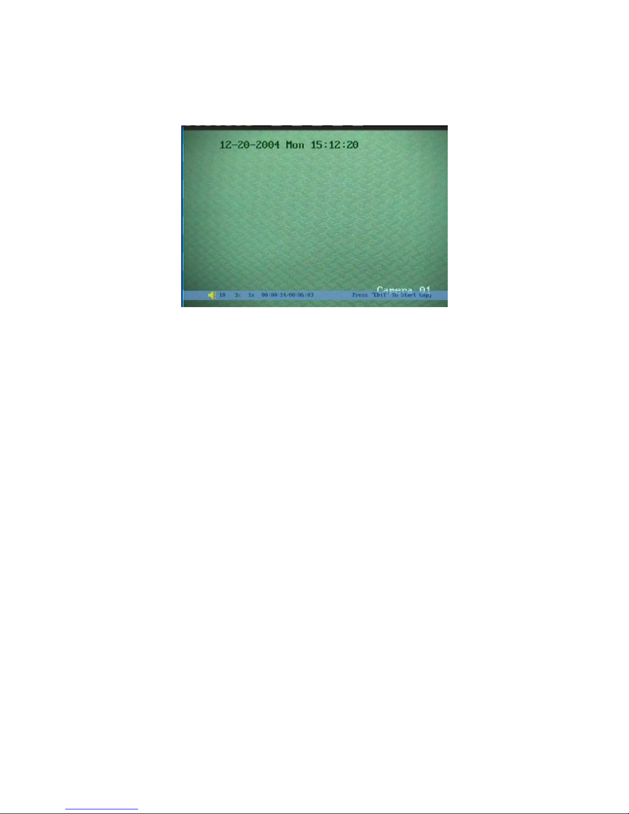
For 4, 8, 16 channels NVR, if you select “Second” channel, two channels will be played back. The operation o
single channel playback is as follows:
The information in the bar at the bottom of the screen represents respectively: volume, play progress, play speed,
play time and total time.
Press 【MENU
【←】(
The normal play speed is “1x”, 【↑】to add the play speed, there are three selections represented as 2, 4, 8
multiples, press
During the play process, press【Enter】key to pause, press again【Enter】key to continue. In single frame
mode, every press of【Enter】key to play one frame forward;
Use【EDIT】key to copy a segment, there is the detailed introduction in the record files backup.
【
ESC】key to exit the play picture.
backward),
【↓】
】
key to cancel information column.
【→】
to reduce play speed, there are four selections as 1/2, 1/4, 1/8 multiple and single frame.
(forward) to adjust the play progress, the level in diagram is 3%;
Backup a Recorded File
Note: Operator must have “Playback” operation authority.
Connect backup hardware (USB flash disk, USB hard disk, USB CDRW or IDE CDRW), press the 【PLAY
on the front panel or Remote. Select a username and input the correct password to enter into the playback sub-menu.
Backup file:
backed up. Execute the “Search” to list files meeting the search criteria.
Note: A Maximum of 400 files can be listed; scroll through “ Page selection” to view available file choices. I
there are more than 400 files, shorten the time period.
Select or input a channel number, file type, and start & stop time (or card number) of the files to be
】
12/7/2005https://serenity-support.gviss.com/html/doc/UserManNVR.htm
Page 23
p
Page 23 of 79User Manual NV
R
Playback
Playback
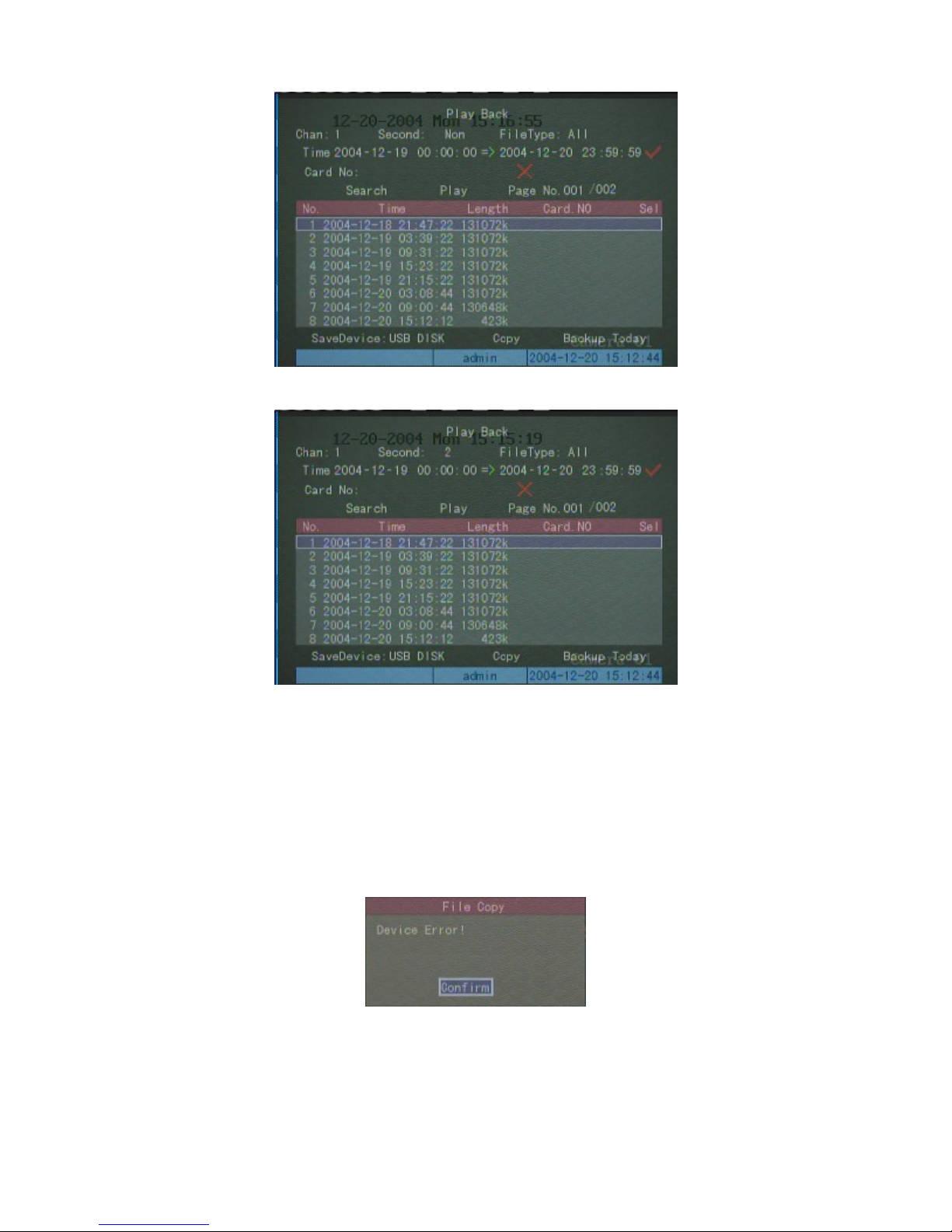
Select the file to be backed up from the file list (turn the pages by using the “ Page No”, use the
keys to move the scroll bar, use the 【EDIT】key to alter the status to “9”.
【↑】,【↓】
Select “Save Device” This refers to the ability to copy a file to another device (CD ROM, USB, etc) to Then press
the “Copy” button on the Play-back sub menu to copy the files to the backup device. If the files copied successfully,
the message “copy successfully” appears on the screen.
If a dialog box appears with the message “Device Error!” as shown below, check the backup hardware device
hysical connections and ensure the device is powered if it is not powered via the USB cable.
Edit Video File:
during playback you may enable and stop a video segment and edit it through【EDIT】key. The
edited pictures may be saved in the USB storage device. The detailed steps are as follows:
Enter into playback interface.
1)
2)
Press one【EDIT】key to mark the start of the first segment, press again【EDIT】key to mark the end of the
12/7/2005https://serenity-support.gviss.com/html/doc/UserManNVR.htm
Page 24

p
Page 24 of 79User Manual NV
R
first segment.
If you want to edit more than one segment (maximum 30 segments), please repeat step 2.
3)
4)
After completing the segment press【ESC】key and select “Enter” to confirm. The device will copy the chosen
segment to the appointed device. Select “ESC” to cancel the copy operation.
Voice over Internet
【
VOIP】The VOIP function is reserved for future use.
Shut Down
Important Note: The NVR MUST b e shut down using the correct procedure. Serious Hard Disk Drive (HDD)
damage will result if the NVR is not shut down correctly. To shut the NVR down correctly either select the
“Shut Down” button in the Utilities Men u menu, use the
【POWER】
Through the Menu
In the “Utilities” menu, select the “Power Off” button to enter the shut down dialog and confirm the operation.
key on the remote control
.
【POWER】
key on the front panel of the NVR or the
Using the【POWER】key on the NVR front panel or on the remote control
Press and hold the key for more than 3 seconds. When the dialog box appears input the correct username and
assword the press the confirm button to shut down the NVR.
DO NOT use the “Power Switch” on the back panel or disconnect power by physically pulling the power cord or
switching off external power as this may cause significant damage to the Hard Disk Drives (HDDs).
12/7/2005https://serenity-support.gviss.com/html/doc/UserManNVR.htm
Page 25
p
Page 25 of 79User Manual NV
R
Administrator Operating Guide
The following functions can only be carried out by an administrator or users who have been granted “Parameter
Setting” authorization by the administrator. Unless otherwise stated, once the setup described below is finished, the
arameters will come into effect immediately the “Confirm” button is selected. No reboot is required.
About Administrator and the Password
When the DVR is delivered, there is only one default administrator named “admin”with the password “12345”.
The name cannot be modified, however the password can be modified using one of the following methods:-
Press the 【Menu
“
admin” for the “Username”, then press
to enter the administrator main menu.
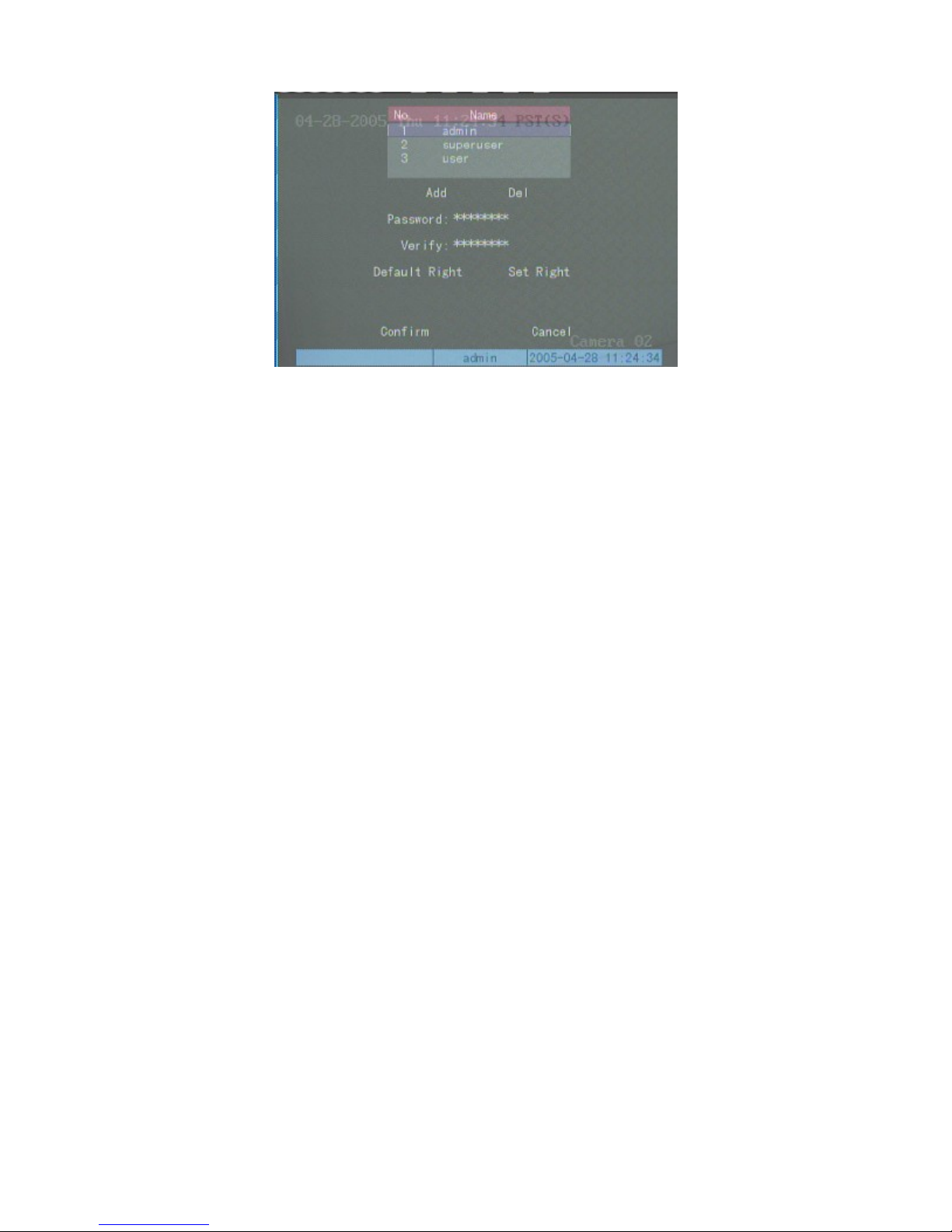
Move the active frame to “User” and select to enter the “user management” sub-menu.
】
key on front panel or Remote and a “Login” dialog box will appear on the screen. Select
【→】
. Input “12345” into the “Password” edit box, then select “Confirm”
12/7/2005https://serenity-support.gviss.com/html/doc/UserManNVR.htm
Page 26
f
Page 26 of 79User Manual NV
R
Move cursor to “password” using the
【Enter】 key again then press the 【→】key to move the cursor to the “verify” input box. Press 【EDIT】, and re-
input the new password for verification. Press 【Enter】, then 【→】 to move cursor to “Confirm”. Press 【Enter】
on the front panel or Remote to finish the password change process. Note the new password comes into effect
immediately.
If the new and verified passwords entered are different, the system will indicate that password setting has failed, and
the cursor will be return to the password edit box for re-inputting a new password.
Note: Do not forget to enable the screen sav er “Require Password” after you complete the paramet ers se tup.
【→】
key. Press the 【EDIT】key and input a new password. Press the
Modify Unit Name and Device ID
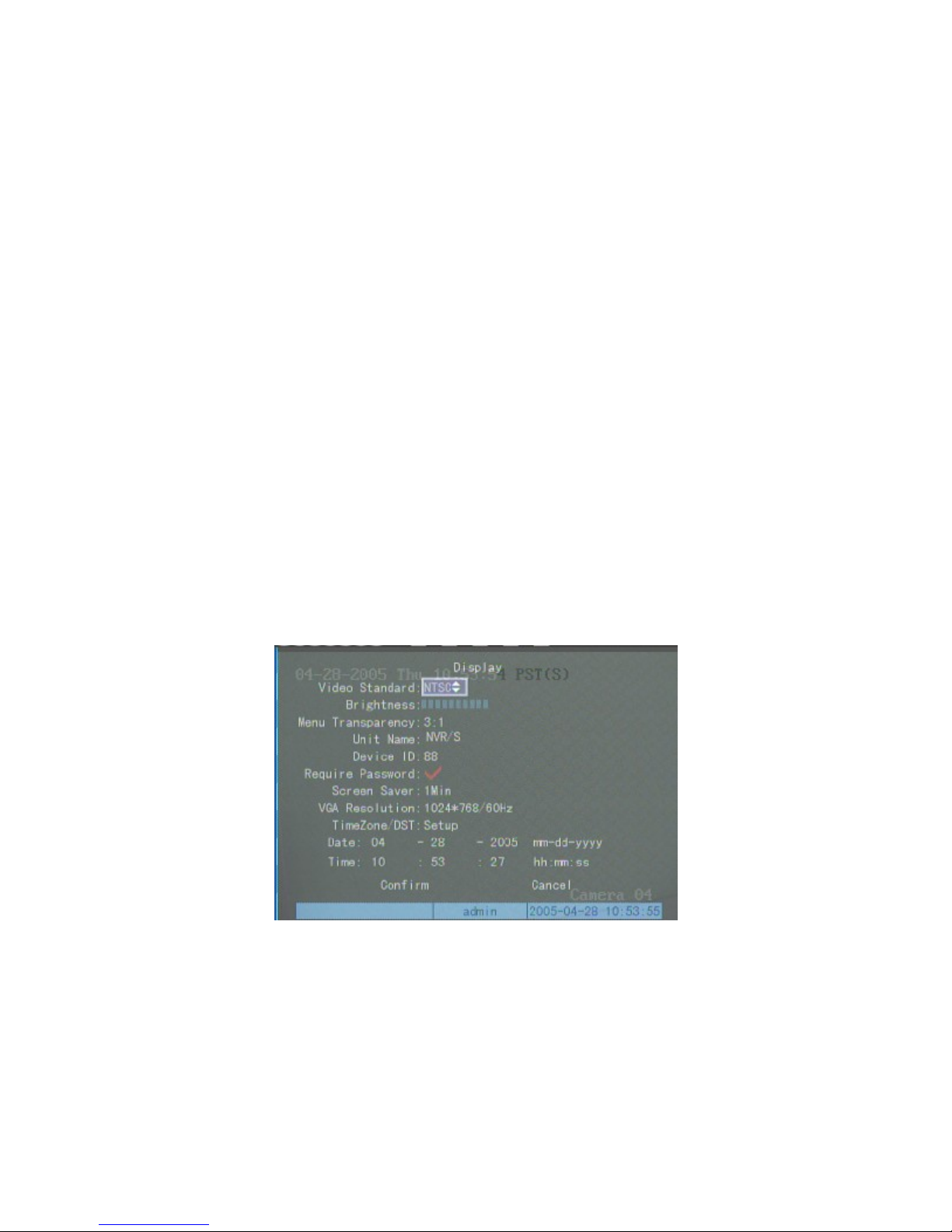
Select the “Display” setup sub-menu.
The default unit name is “NVR[MAC]”. This name can be modified using the 【EDIT】 key, 【*/#/$】 key and
the numeric keys.
The default device ID is ”01”. The device ID can be modified directly using the numeric keys. The valid range o
values for Device ID is 01-99.
Press the “Confirm” button to save the new information, or press “Cancel” to return the information to the original
values.
12/7/2005https://serenity-support.gviss.com/html/doc/UserManNVR.htm
Page 27
Page 27 of 79User Manual NV
R
TIFF (Uncompressed) decompressor
QuickTime™ and a
are needed to see this picture.
Video standard
In the “Display” sub-menu, you can select PAL or NTSC in “Video Standard”, it will come into effect after the
setup is finished. The default video standard is NTSC.
Local monitor - Preview properties
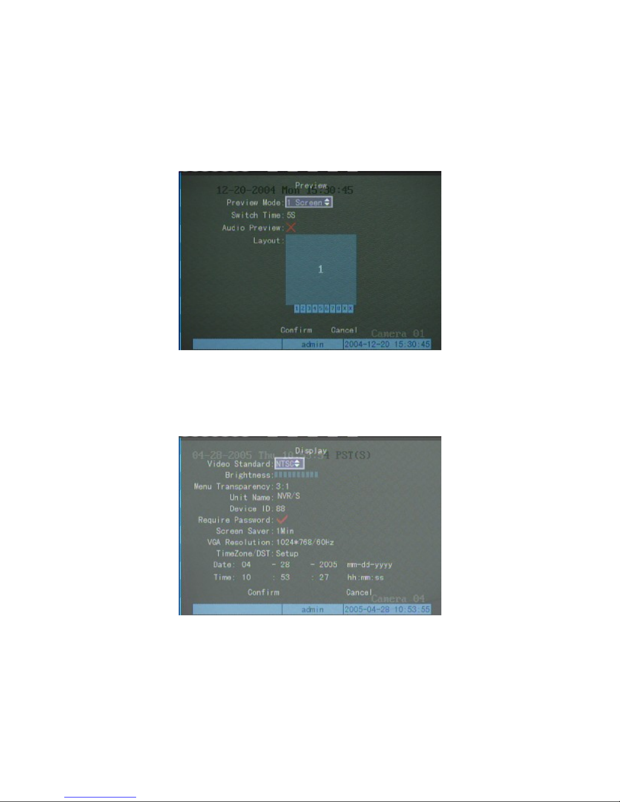
Select the “Preview” sub-menu.
Preview mode: 1 screen, 4 screen, 9 screen and 16 screen options are selectable;
Switch time: 5 seconds, 10 seconds, 20 seconds, 30 seconds, 1 minute, 2 minutes, 5 minutes, no switch;
Need to preview audio (9) or not (×) ;
12/7/2005https://serenity-support.gviss.com/html/doc/UserManNVR.htm
Page 28
Page 28 of 79User Manual NV
R
To set up channel sequence in Preview: input the display channel number directly in the frame (device under 10
channels, input 0, 1~9, device with more than 10 channels, input 00, 01~16, input 00/00 means this position need not
display);
【ESC】 key to erase all new data and return values to their settings prior to selecting this sub-menu.
Select “Confirm” when Preview Property setup is finished to save the altered data. Select “Cancel” or press the
Time Zone and DST
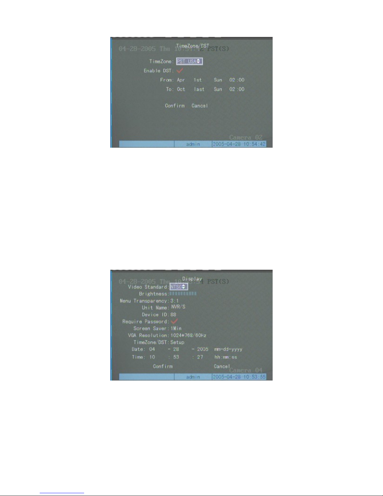
Select the “Display” sub-menu for time zone and Daylight Saving Time (DST) settings.
Select “TimeZone/DST” sub-submenu to display the following input screen
12/7/2005https://serenity-support.gviss.com/html/doc/UserManNVR.htm
Page 29
b
Page 29 of 79User Manual NV
R
To enable automatic DST time alteration for the first time, select your time-zone then enter the exact date & times that
DST will start and end for the current year then select confirm to save the input data.
System Time
Calibrate System Time Manually
Select the “Display” sub-menu, input the current date and time into “Date” and “Time” fields, select “Confirm”
and the modified date and time will be updated on the NVR. Select “Cancel” or press the 【ESC】key to cancel the
update and return the NVR time to the values set when the menu was selected.
Change image attributes
You can set different image attributes to every channel (including display mode and display position), If identical
display attributes are required for every channel, use the “Copy”
selected channel to “All” channels after the display attributes have been set for the current channel.
The On-Screen Display (OSD) attributes of a selected channel can be set as follows:- Select the “Image” sub-
menu.
utton to copy the display attributes of the current
12/7/2005https://serenity-support.gviss.com/html/doc/UserManNVR.htm
Page 30
p
p
p
b
r
b
Page 30 of 79User Manual NV
R
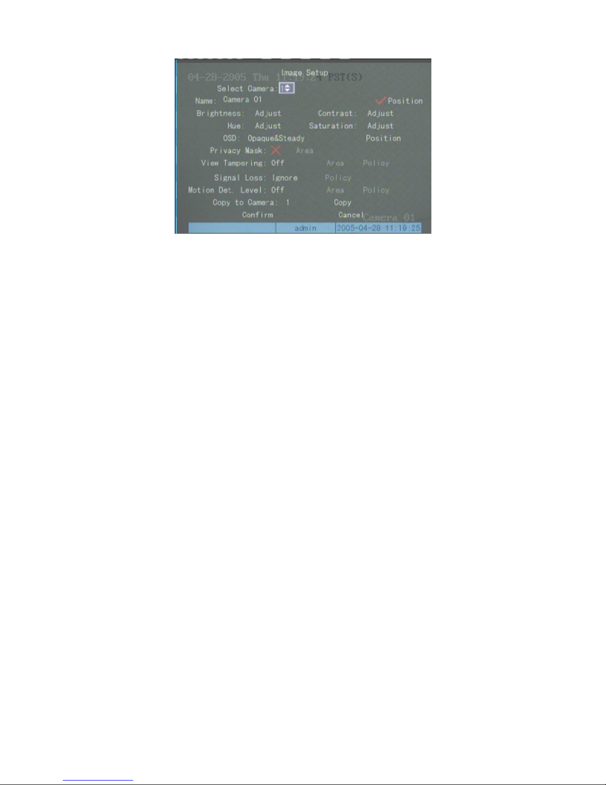
Move the cursor to “OSD Text Options” for the selected channel. The following 5 self-explanatory options are
available for the OSD text options:-: -Opaque&Steady, Opaque&Flashing, Transparent&Steady,
Transparent&Flashing, No Display.
Enter into the right side “Position” of “OSD” option, and a picture of designated channel will appear. The
osition of OSD displayed in the graphics can be adjusted easily with direction keys. After the position is confirmed,
ress 【Enter】in front panel to return to “Image” setup menu interface. Press【ESC】to cancel the adjustment of
OSD position.
The OSD Text and position properties can be copied to other channels if required, or the OSD Text & position
roperties can be set for each channel individually as described above
After all the settings are complete, press “Confirm” on the “Image Setup” menu and the parameters set will come
into effect immediately. You can see the OSD Text and position properties after modification. Press “Cancel” or the
【
ESC】key to erase the new setup data and return to the previous data settings.
Camera Name
Set Camera/Channel Name
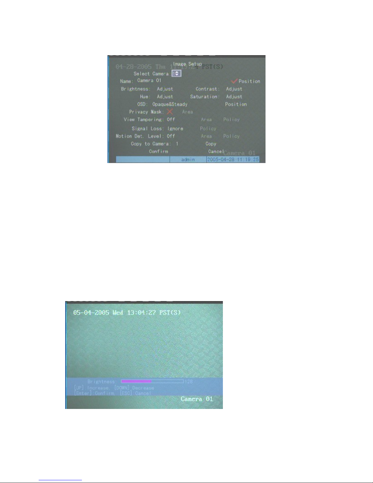
Select “Image Setup” sub-menu and set the Camera/Channel names as follows:-
Step one: Select Camera/Channel number.
Step two: Move the active box to the camera/channel name edit box, then press the 【EDIT
combination of the numerical keys and the */#/$ key to set the camera name.
Note : Use the 【 A 】
capital letters or symbols are currently selected. The camera/channel name can consist of numerals, capital & lowe
case English letters or symbols. Each camera/channel name can contain up to 32 characters.
Step three: Press the 【Enter】key to exit edit status.
Repeat above steps to alter or input other camera/channel names.
After defining the camera/channel name, press the “Confirm”
new camera name is displayed as an OSD as defined in the OSD Text & Position settings onto the picture of the
utton to activate the bottom menu left hand box to show whether numbers, small letters,
utton and the new camera name will be saved. The
】
key. Use a
12/7/2005https://serenity-support.gviss.com/html/doc/UserManNVR.htm
Page 31
b
Page 31 of 79User Manual NV
R
relevant camera. If you press the “Cancel” button or the 【ESC】key, you will cancel the camera/channel name
data update and the name will return to display the previous name data..
Video Parameters
The video parameters can be adjusted individually for every camera, or the attributes of a single camera setting
may be copied to other cameras. This is achieved as follows:-
Step one: Select the “Image Setup” sub-menu;
Step two: Select the camera/channel number
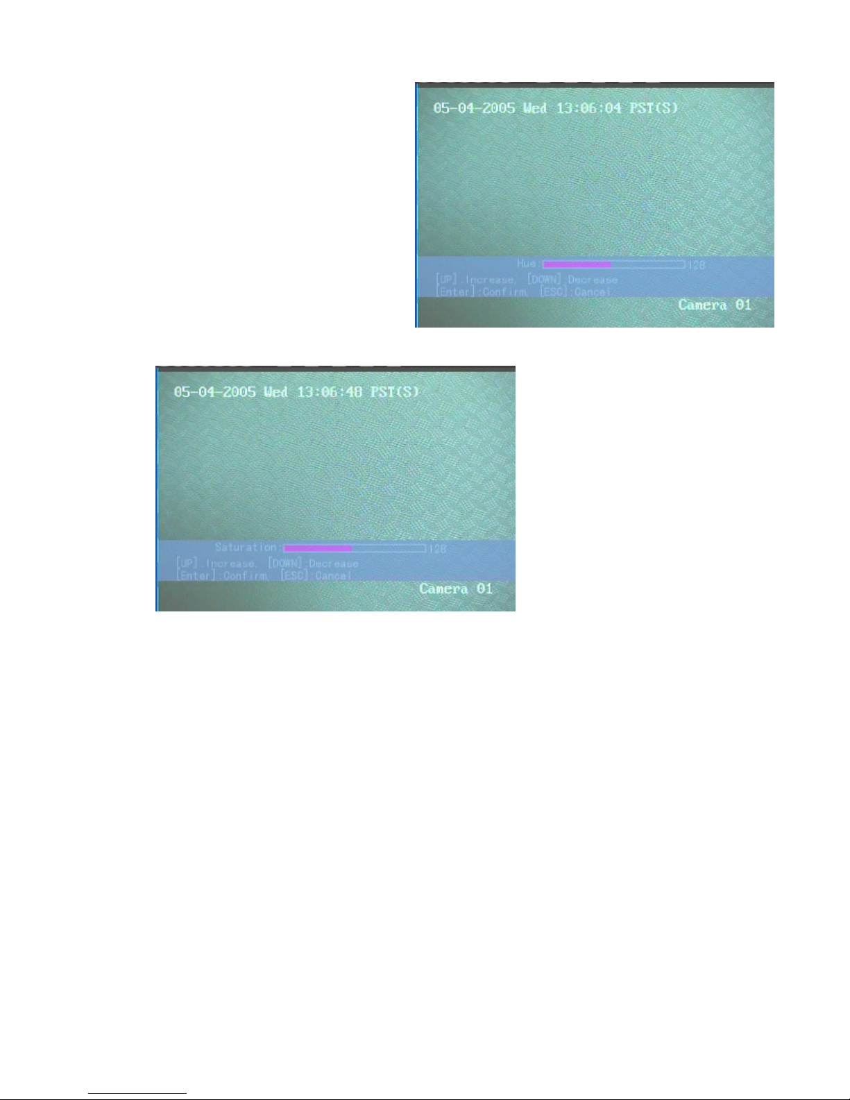
Step three: Press the “adjust”
Parameter Names. Press “Enter” to select the corresponding adjustment menu.
utton on the right hand side of the Brightness, Contrast, Hue or Saturation
12/7/2005https://serenity-support.gviss.com/html/doc/UserManNVR.htm
Page 32
Page 32 of 79User Manual NV
R
There is an information bar at the bottom which allows the user to increase or decrease, and confirm or cancel
video parameters . Use the
same time. After you are satisfied with the image displayed, press the 【Enter】key to save the result and return to the
“Image Setup” sub-menu.
This setting can be duplicated to other cameras. After all the settings are completed, press “Confirm” on the
“Image Setup” sub-menu to make the new parameters effective. If you want to cancel the setting, press “Cancel” on
the “Image Setup” sub-menu or press the 【ESC】key on the front panel.
【Ç】or【È】
to adjust the selected picture parameter directly and preview the result at the
12/7/2005https://serenity-support.gviss.com/html/doc/UserManNVR.htm
Page 33
Privacy Mask Area
R
Page 33 of 79User Manual NV
The Privacy mask feature is designed to provide protection by preventing a user from viewing a sensitive area of
the surveillance picture. Note that this feature is only useful for fixed camera views.
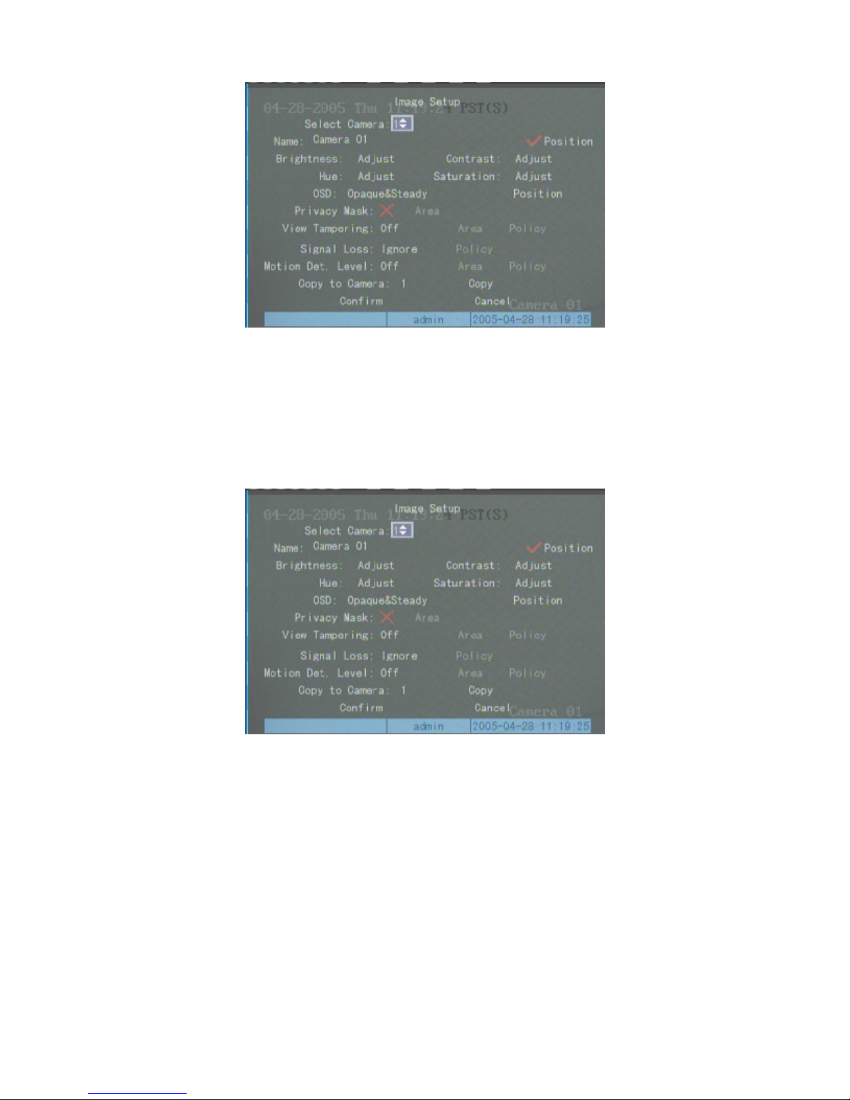
To set a privacy mask, select the “Image Setup” sub-menu.
Select a camera and toggle the “Privacy Mask” option status to be “9” using the 【EDIT
the mask function “area” selection to the right hand side of the Privacy Mask menu selection item. The Area feature
allows the user to define the mask area.
】
key. This will enable
12/7/2005https://serenity-support.gviss.com/html/doc/UserManNVR.htm
Page 34

p
p
p
N
Page 34 of 79User Manual NV
R
The picture is sub-divided into 22
individually selected to display or mask (hide) the transmitted video within that sub-pane. To mask a particular sub-
ane area, move the flashing red sub-pane selector to the required sub-pane using the. To mask that area press the
【
area downward,【↑】shrinks the masked area upward,【→】enlarges the masked area to the right,【←】shrinks the
masked area to the left.
the effect as shown in the example below:
】
EDIT
ane.
rivacy mask area setup or choose “Cancel” to remove the setup. If it is successfully setup, preview this channel to get
key. To enlarge or reduce the masked area use the direction keys as follows:-
Only one contiguous masked area can be designated in each channel. The minimum masked area size is 1 sub-
Press【Enter】after finishing to return to “Image Setup” sub-menu. Select “Confirm” on the menu to save the
*15 (NTSC or
22*18 for PAL)separately addressable sub-panes which can be
【È】
enlarges the masked
Tampering Setup
OTE : THE FOLLOWING TAMPERING FEATURE IS NOT SUPPORTED IN THE CURRENT VERSION OF
THE SERENITY NVR.
12/7/2005https://serenity-support.gviss.com/html/doc/UserManNVR.htm
Page 35
r
p
Page 35 of 79User Manual NV
R
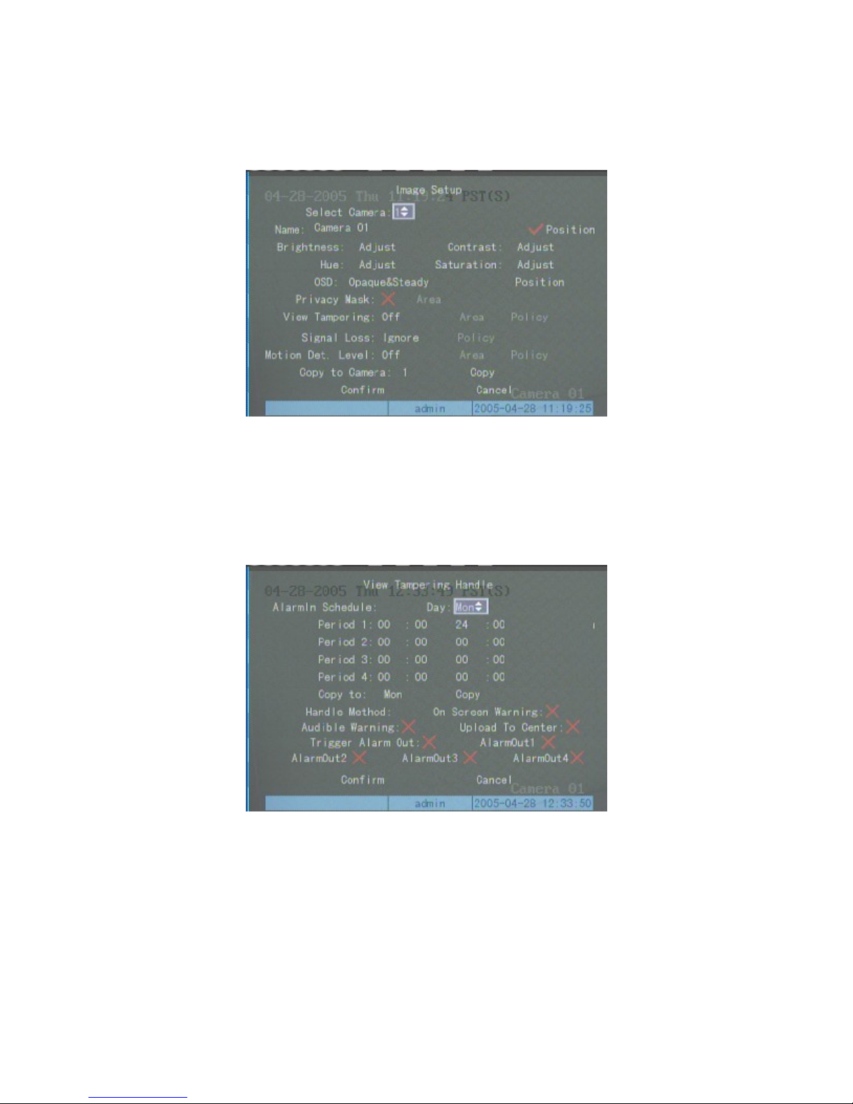
The purpose of view tampering setup is to prevent malicious blockage of the lens. Thus, the setup of deal policy is
needed besides the setup of view tampering area.
Enter into “Image” setup interface.
There are four options for the “View Tampering”, they are: off, low, normal, high. You can select low, normal o
high to active the view tampering alarm area setup and process functions. Enter into correspond setup interface to setup
area, the setup method is the same as that of privacy mask setup except that mask area can be set to cover the entire
icture maximally.
Enter into “Policy” of view tampering alarm. The handle policy can be defined in “View Tampering Handle”
interface.
You can select one or more handle mode. After the setup, select “Confirm” and return to “Image” setup interface.
Then execute “Confirm” in “Image” setup menu to save the parameters. Please reboot the NVR to make the parameters
become into effect. Select “Cancel” or press 【ESC】key in front panel to give up the set parameters.
Signal Loss Alarm Setup
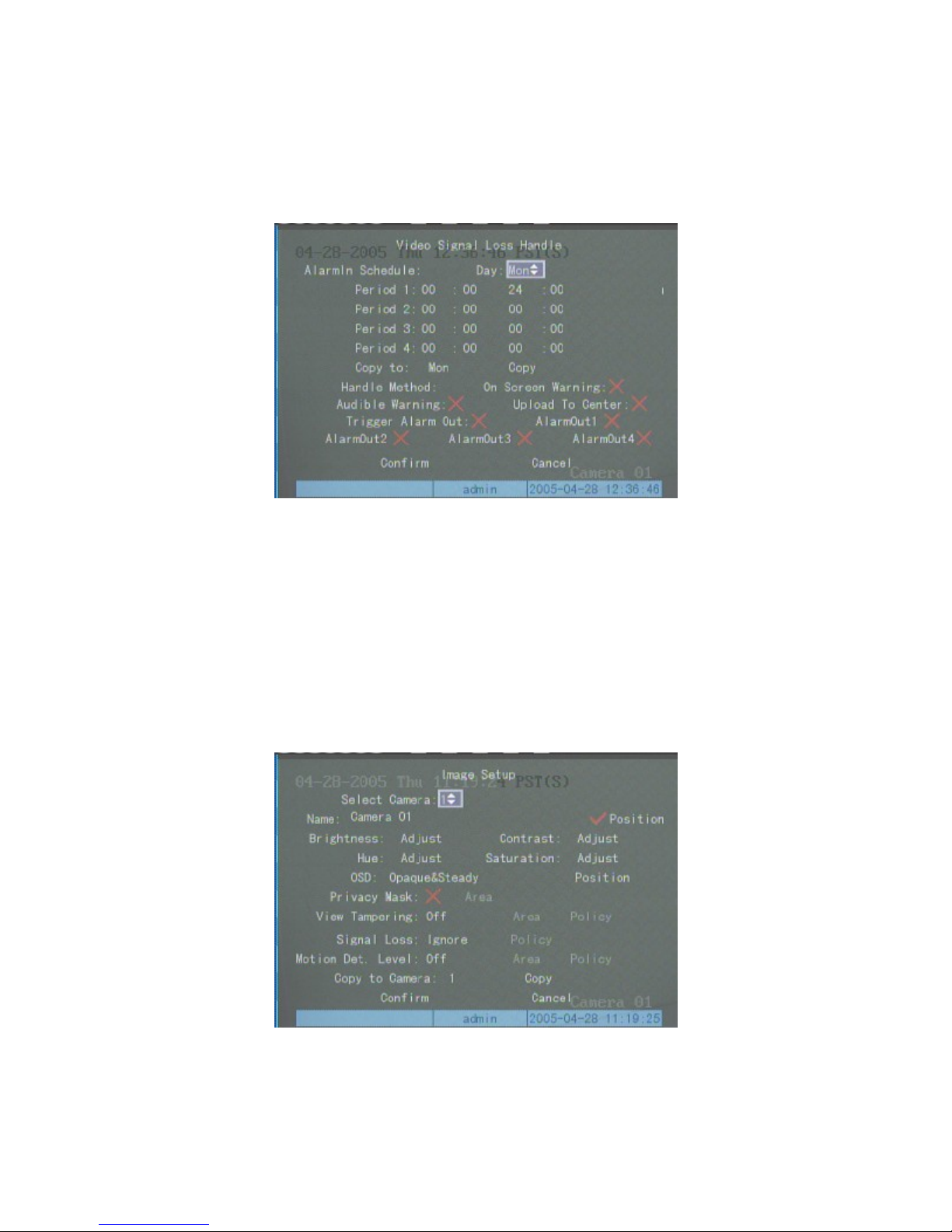
Select the “Image Setup” sub-menu and toggle the “Signal Loss” selection from “Ignore” to “Handle” using the
12/7/2005https://serenity-support.gviss.com/html/doc/UserManNVR.htm
Page 36
R
Page 36 of 79User Manual NV
R
【Ç】 or 【È】 keys. This will activate the Signal Loss “Policy” menu item. Use the 【→】 and then the
【
Enter
The policy sub-menu allows the user to select one or more response modes or none at all by leaving all response
modes unselected. After altering the policy for handling the Video Signal Loss , select “Confirm” to return to the
“Image Setup” sub-menu. Select “Confirm” in the “Image Setup” menu to save the altered - parameters. The NV
must be rebooted to make these new changes effective. Select “Cancel” or press the【ESC】key on the front panel to
erase the altered data and to reset the parameters to their previous settings.
】
key to select the “Policy” to display the sub-sub-menu as shown below.
Motion Detection Setup
Select “Motion Detection” on the “Image Setup” sub-menu.
Define the sensitivity level of motion detection
There are 7 sensitivity setting levels which can be selected. These are “Off”, 0 (the lowest sensitivity level) to 5
(the highest sensitivity level).
Set the Motion Detection Area(s)
12/7/2005https://serenity-support.gviss.com/html/doc/UserManNVR.htm
Page 37

Page 37 of 79User Manual NV
R
Select “Area” option on the “Motion Detection” section of the “Image Setup” sub-menu and press the 【Enter
key to enter the motion detection area selection setup.
The top left yellow frame is the motion detection setup frame, the picture is divided into 22x15 (NTSC or 22x18
for PAL) sub-panes. The maximum area that can be defined for motion detection is 12*12 panes and the minimum area
is one pane. The following sequence of selections should be used to set the motion detection area.
【↑】【↓】【←】【→】
【EDIT】: Select that sub-pane for motion detection. The selected sub-pane turns red.
: Move the “yellow frame” to any place;
】
【↓】
shrinks the area to the left.
【
【PREV】: Clear all the areas set;
【
【ESC】: Cancel the setup and return to “Image Setup” sub-menu.
The following shows an example of a motion detection area after setup is complete.
Enlarges the area downward,
PTZ】: Select the entire picture as the motion detection area;
Enter】: Finish setup, save and return to “Image Setup” Sub-menu;
【↑】
shrinks the area upward,
【→】
enlarges the area to the right,
【←】
12/7/2005https://serenity-support.gviss.com/html/doc/UserManNVR.htm
Page 38
p
Page 38 of 79User Manual NV
R
Set Motion Detection Alarm Handling
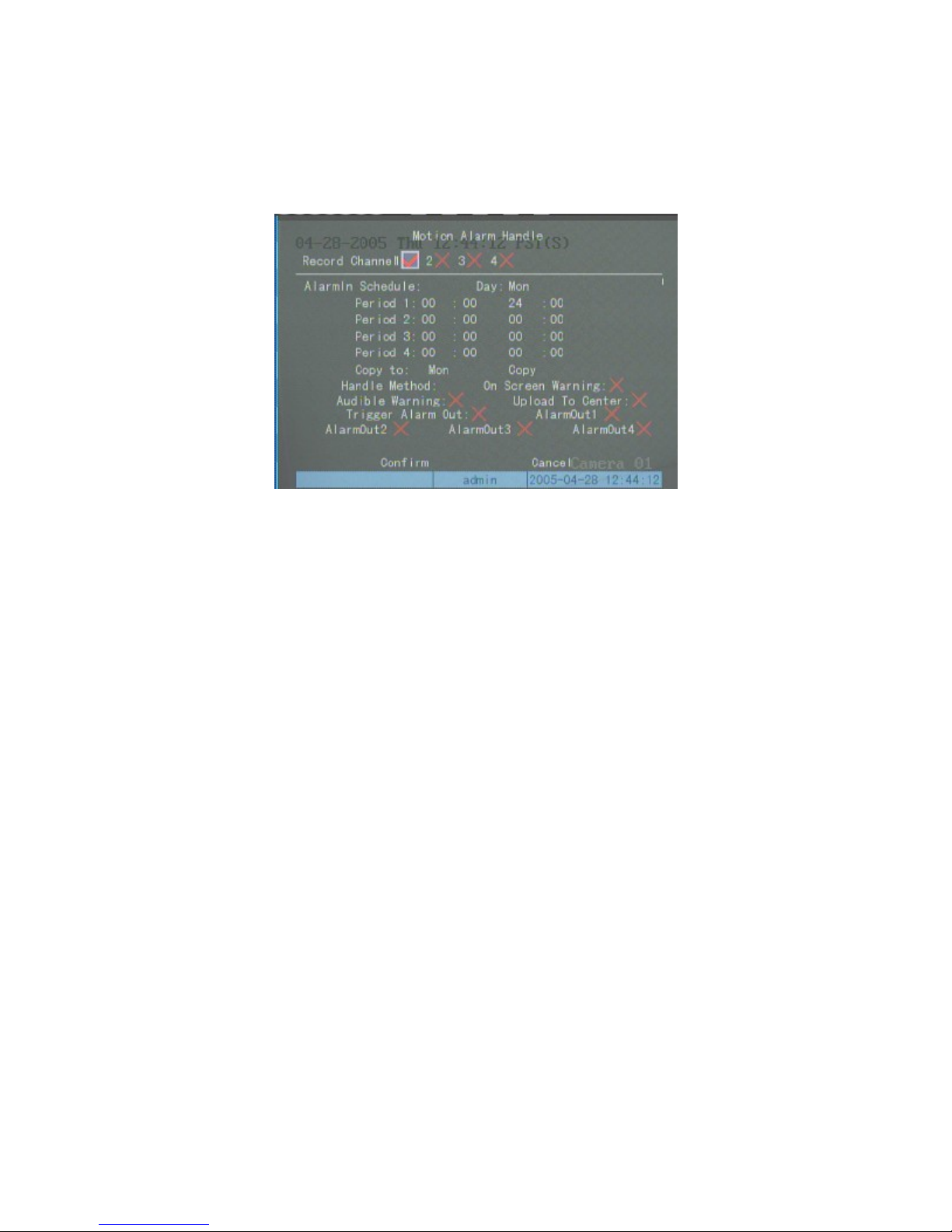
Select “Motion Detection” “Policy” option using the 【Ç】or【È】 keys then press the 【Enter】 key to
activate the Motion Detection Handling menu.
Move the cursor by using【←】or【→】direction keys, then use the 【Enter】or 【EDIT】keys to select an
item.
There are four different alarm schedule periods each day for each motion detection area. You may select multiple
channels by checking the channel list at the top of the screen. The first setting can be copied to all day and other days.
The 【 On Screen Warning 】 setting brings up the video image subject to the alarm on the monitor. By activating
【 Upload to Center 】 \the details of the alarm, but not the video, may be uploaded to a Central Monitoring Station.
Set triggering channels to record or preview and select one or more alarm mode.
After setup, select “Confirm” to return to the “Image Setup” sub-menu. Select “Confirm” on the “Image Setup”
sub-menu to save the selections and parameter set. Reboot the NVR to make these selections permanent. If you want to
cancel the parameter just set, select “Cancel” on the “Image Setup” sub-menu or press the 【ESC】key on the front
anel of the NVR.
Recording Channel Configuration
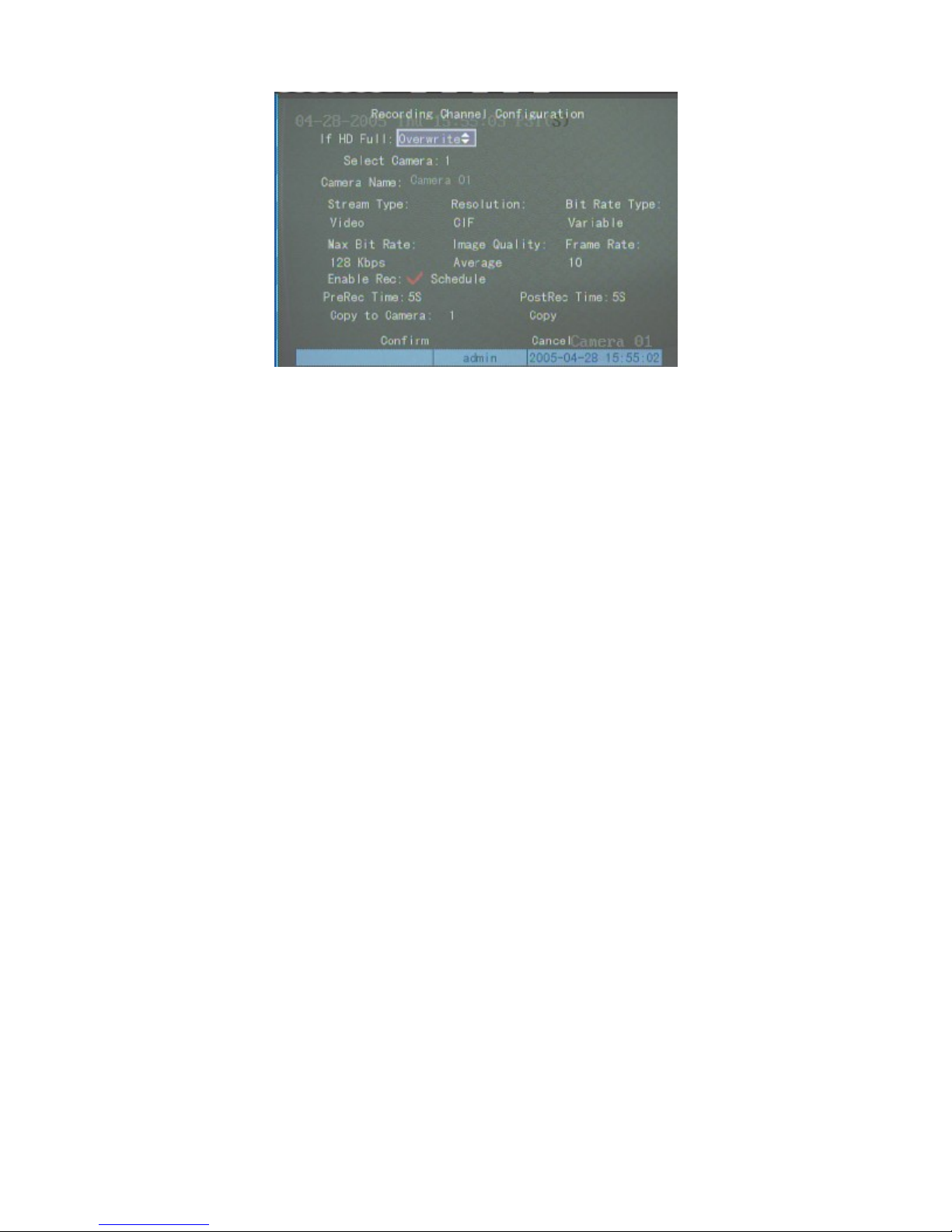
The following recording parameters should be set before starting to record:
Stream Type:
recording only is currently not supported.
Note: The NVR must be rebooted if the stream time is modified.
Resolution:
Encode is started from a specified channel number. Channel 1 to channel 4 use a total of 8 CIF resolution
The selection options are “Video” for video only or “A/V” for audio plus video. Note that audio
The default resolution is CIF. The selection options available are QCIF, 2CIF, DCIF or 4CIF.
12/7/2005https://serenity-support.gviss.com/html/doc/UserManNVR.htm
Page 39

b
Page 39 of 79User Manual NV
R
resources from the DSP level; only the resolution of channel1 can be set as 4CIF, channel2, channel3 and
channel4 can only support CIF resolution. The same rules apply to channel5 to channel8, channel9 to channl12, and
channel13 to channel16.
Note: The NVR must be rebooted if the resolution of any channel is modified.
Bitrate Type:
in “Bitrate” below will be constant at the chosen value. If “Variable” bitrate is selected the “Bitrate” selected below
will act as the maximum allowable value for the bitrate.
Bitrate:
192kbps, 224kbps, 256kbps, 320kbps, 384kbps, 448kbps, 512kbps, 640kbps, 768kbps, 896kbps, 1M, 1.25M, 1.5M,
1.75M, 2M. A “By User” selection is also available and any value between 32kbps and 8192kbps can be set.
Image Quality:
applied, but if the Bitrate setting is low the image quality cannot be adjusted.
Image quality parameters can be adjusted only if the Bit Rate Type is selected as Variable. The quality
descriptions are: Highest, Higher, High, Average, Low, Lower, Lowest. Note that the six levels apply to the quality
available according to the previously chosen Maximum Bitrate.
Frame Rate:
PreRecord Time:
will occur from the time period prior to the alarm event set here until the end of the Post-Record time after the alarm
event – see below. The available selections are “NoPreRecord”, 5s, 10s, 20s, 25s, 30s. The default is “No Pre-record”
Note:- The NVR must be rebooted if a Pre-Record time is set.
Post Record Time:
This refers to the time recorded after the alarm. This selects the Post-Record time to be recorded after an alarm
has cleared. Storage at the set rate and quality will occur from the time period prior to the alarm event (Pre-Record
Time) set above until a time (set here as Post-Alarm time) after the alarm has cleared. Note that recording will be
continuous whilst the alarm is active irrespective of the time period over which that occurs. The available Post-Alarm
Record time selections 5s, 10s, 30s, 1minute, 2minutes, 5minutes, 10minutes.
Note:- The NVR must be rebooted if a Post -Rec ord time is set.
The “Recording Channel Configuration” sub-menu is as shown below:-
The selection options are “Fixed” or “Variable”. If “Fixed”
The following values can be selected directly 32kbps, 48kbps, 64kbps, 80kbps, 96kbps, 128kbps, 160kbps,
If the Bit Rate Type chosen is Fixed, the Maximum Bitrate for the appropriate video stream is always
Full(NTSC 30fps, PAL 25fps,), 20, 16, 12, 10, 8, 6, 4, 2, 1, 1/2, 1/4, 1/8, 1/16.
itrate is selected, the actual bitrate selected
This selects the PreRecord time to be recorded if an alarm occurs. Storage at the set rate and quality
12/7/2005https://serenity-support.gviss.com/html/doc/UserManNVR.htm
Page 40
b
r
Page 40 of 79User Manual NV
R
Record Schedule
Toggle “Enable Record” From “X” to “9” using the 【Enter
the right hand side of “Enable Record” and press【Enter】to select the “Schedule” setup sub-menu:
To set up all day (24 Hours) recording:-
1)
Toggle “All Day” from ”X” to “9” using the 【Enter】 or 【EDIT】keys;
Select one of the following Recording Options:
2)
If the same selections are required on more than one day, select the “Copy to” option, select the day to be set with
】
or 【EDIT
】
keys. Select the “Schedule”
these identical parameters then press the “Copy” button to copy the current parameters to the selected “Copy
to” day.
3)
Press the “Confirm” button to set the parameters for the days set.
Setting up the record time parameters:
1)
Toggle “All Day” from “9” to “×” using the 【Enter】 or 【EDIT】 keys;
There are 4 separately definable recording time segments which can be set for each day of the week. Every
2)
segment has a start time, an end time and a Recording Option.
and must be set in the order they occur during the day.
3)
Select “Copy to” and press 【Ç】or【È】 to choose a particular day or “All” for all days. Next select “Copy”
Note - time segmen ts cannot be ov erlappe d
and press【Enter】 to copy these parameters to the specified day or all days. A pop-up dialog box will advise
when the copy procedure is complete. Skip this step and proceed to step4 if you do not want to copy these
parameters
4)
Press the “Confirm” button to permanently save the parameters, and this will confirm settings for each day fo
which parameters were copied.
In the “Record Channel Configuration” sub-menu select “Confirm” and press【Enter】to save the parameters
Note:- The NVR mu st be rebooted before the “Record Channel Configur ation” parame ters entered ab ove
become effective/active.
Press the “Cancel” or【ESC】keys to cancel the parameters setting operation and return the values to the values
stored prior to the recent changes.
utton to
12/7/2005https://serenity-support.gviss.com/html/doc/UserManNVR.htm
Page 41
Page 41 of 79User Manual NV
R
Notes:
If the Record Option selection includes “Motion Detection” then a valid motion detection area and
1)
sensitivity must be set up before motio n detection recording will occur.
If the Record Option selection includes “Alarm” then valid Alarm parameters must be set up before “On
2)
Alarm” recording will occur..
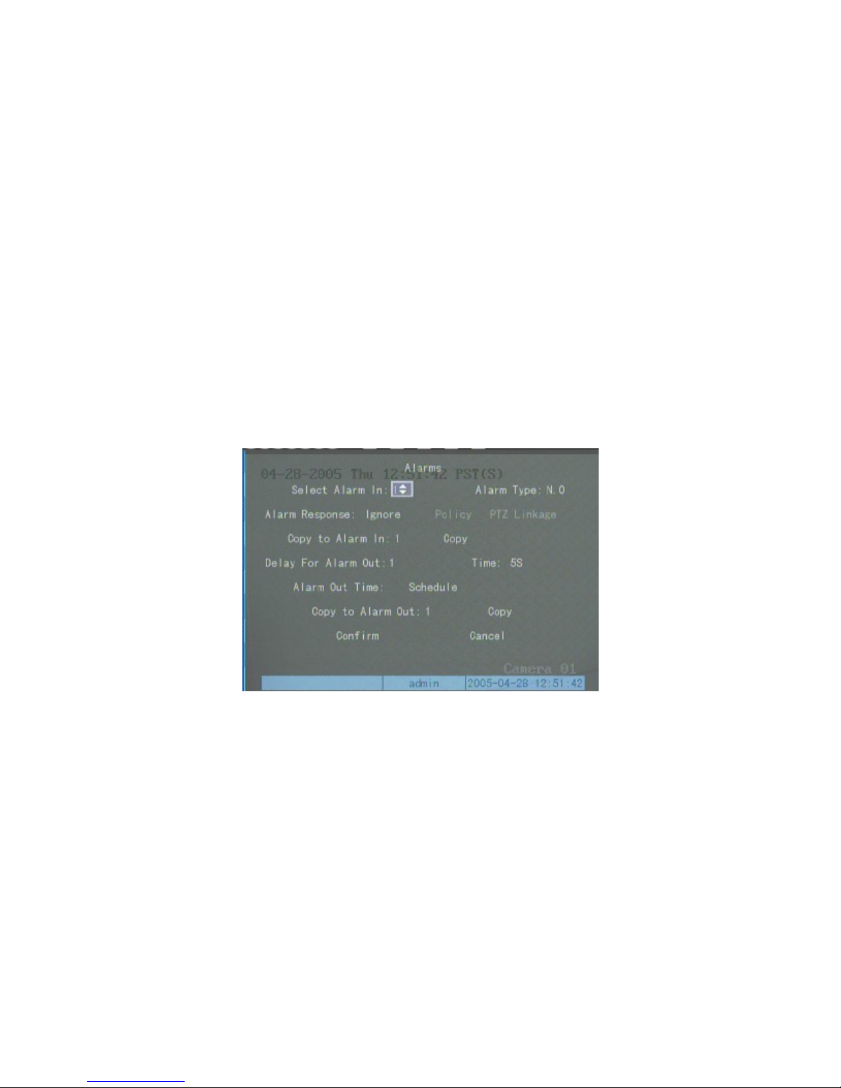
Alarm Parameters Setup
Select the “Alarms” icon from the main screen menu, press 【Enter
below. In the “Alarm” setup sub-menu, select the digital alarm input number (1 – 8 or –16 depending on NVR model)
then select ”DI Normal Condition”. The selection Options are “NO” (Normally Open) or “NC” (Normally Closed),
then set the other parameters as detailed below.
Note: Select the “Confirm” button on the “Alarms” sub-menu then press【Enter】to save the inserted
Alarm parameters, then reboot the NVR to activate the parameters.
】
to select the “Alarms” sub-menu as shown
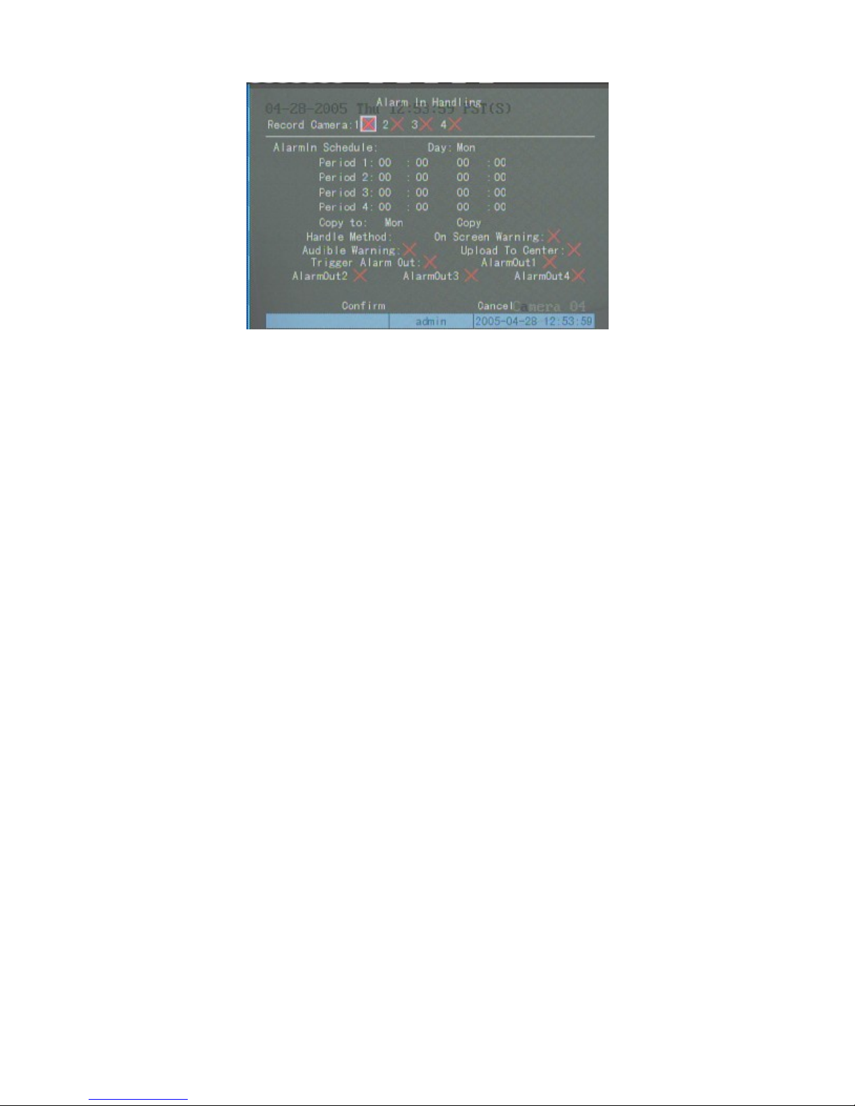
Digital Input (DI) Alarm Handling Sub-menu
Select then toggle the “Alarm Response ” parameter from “Ignore” to “Response” using the 【Ç】 or 【È】
keys. Next select the “Policy” button and press the 【Enter】key to select the “DI Alarm Handling” sub-menu.
12/7/2005https://serenity-support.gviss.com/html/doc/UserManNVR.htm
Page 42
Page 42 of 79User Manual NV
R
The “DI Alarm Handling” sub-menu can be used to set up a number of alarm-related parameters.
Set Video Channel to record on Receipt of DI Alarm:
will start recording. If “warn on monitor” is enabled the monitor will display on the local monitor a preview of the
channels being recorded.
Set DI Alarm Active Handling Time Period:
Each time period must be in time sequence order and time periods cannot overlap each other. Time periods set for the
current day can be copied to other days.
Handle Method:
Note: “Upload to Center” is only available for the
After “DI Alarm Handling parameter setup is complete, press “Confirm” to return to the main “Alarm” menu.
This menu man be used to copy the Alarm Handling parameters from the current DI Alarm to other DI Alarm inputs.
After all DI Alarm parameter setting is complete, press “Confirm” on the “Alarm” menu to save the parameters (and
for each day copied).
Note:- The NVR must be rebooted before the “Alarm” para meters entered above become effective/active.
The previous parameters can be restored by pressing “Cancel” or the ESC key instead of “Confirm”.
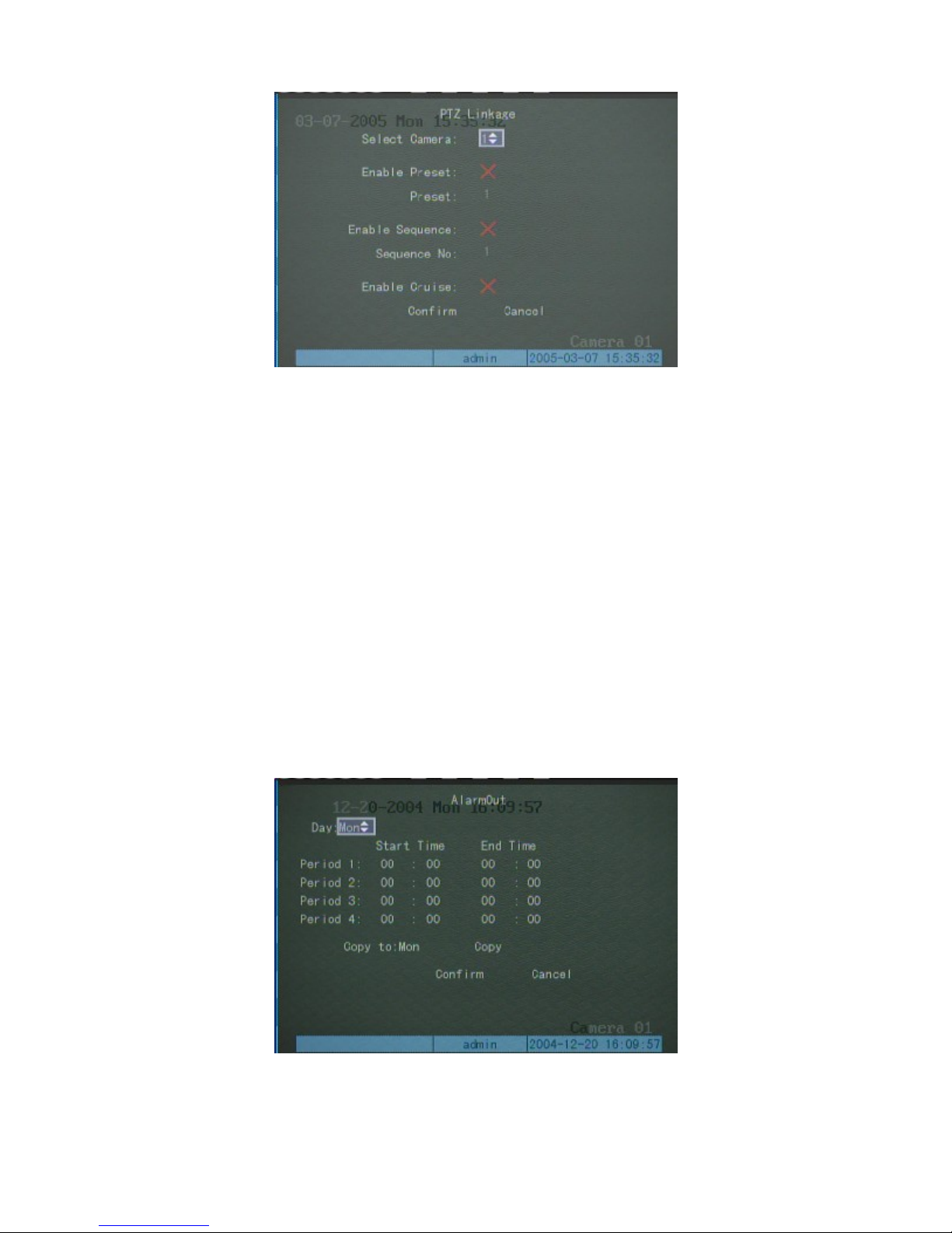
Set PTZ Response
In the “Alarm” setup sub menu select the “PTZ Linkage” button and press 【Enter】to select the “PTZ Linkage”
sub-menu as shown below:-
Select and set day first, then set the time parameters for that day.
You can select one or more response methods.
Serenity Enterprise Edition
When a DI alarm activates, all the channels selected “9”
.
12/7/2005https://serenity-support.gviss.com/html/doc/UserManNVR.htm
Page 43
Page 43 of 79User Manual NV
R
This sub menu can be used to select a preset, a sequence, or a patrol (“Cruise”) on a particular camera in response
to a DI Alarm.
Once PTZ Response setup is complete, select “Confirm” then press 【Enter】, to return to the “Alarm” main
menu
Note that the PTZ Response parameters can be copied to other DI alarm inputs.
.
Press “Confirm” on the “Alarm” menu to save the parameters then reboot the NVR to make the parameters take
effect. Press “Cancel” or the 【ESC】 key to restore the previous parameters.
Note: One alarm input can trigger preset, sequence, or series of multi channels.
Digital Output Alarm Response
You can define the delay time and effective time of every alarm output. Only at the effective time, will the alarm
output be triggered
In “Alarms” setup interface, select one alarm output, then select delay time options: 5s, 10s, 30s, 1minute,
2minutes, 5minutes, 10minutes. The actual alarm output time = alarm input remain time + alarm output delay time.
You can press “Stop AlarmOut” button in “Utilities” interface to clear the alarm output.
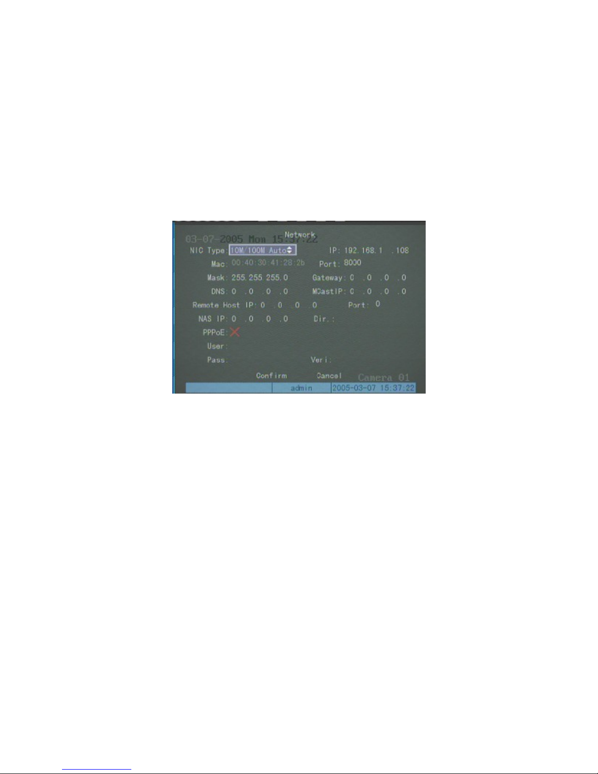
In “Alarms” setup interface, focus on “Schedule” button on the right side of the “AlarmOut Time” and press
【Enter】to enter into “AlarmOut” setup interface:
。
Select date first, then set time segment. Time segment is set according to the sequence, the time of segments shall
not overlap, no skip is allowed for setting. After the precaution time of a certain day is set the parameters already set
can be copied to other dates
12/7/2005https://serenity-support.gviss.com/html/doc/UserManNVR.htm
Page 44
p
k
k
r
Page 44 of 79User Manual NV
R
When setting is finished, move the focus to “Confirm”, press【Enter】, return to “Alarm” setup interface.The
arameters can be copied to other alarm output.
Press “Confirm” in the “Alarm” setup interface to save the parameters. Reboot the NVR to make the parameters
into effect. You can press “Cancel” or【ESC】key to undo the parameter changes.
Network parameters
Select the “Network” icon on the main screen menu and press “Enter” to select the Network sub-menu shown
below. After finishing the network parameter the setup, select “confirm” to save parameter set, and the parameter will
take effect after the device reboot.
Network card type
Default is 10M/100M auto, options are 10M half-duplex, 10M full-duplex, 100M half-duplex, 100M full-duplex
etc.
IP address
segment. DHCP protocol is applied by setting your IP address setting to 0.0.0.0
Edition
sub-menu.
Port Number
Mask IP address
Used to mark off the sub-net segment.
Gateway address
communication between the different network segments.
NVR NS (Naming Server) address
This IP address must be unique, and cannot conflict with any online or working station in the same networ
The end user can access an NVR by that IP address or by using the NVR naming service, provided for
users and located in the Serenity Intelligence Center.
Enter the default IP address for the NVR Naming Service (70.85.128.120) in the “NVR NS” field on the Networ
Port Number must be more than or equal to 8000.
If the NVR is behind a router, you need to set a gateway address from the network administrator fo
Enterprise
12/7/2005https://serenity-support.gviss.com/html/doc/UserManNVR.htm
Page 45
Page 45 of 79User Manual NV
R
The NVR uses PPPoE protocol to connect into the internet to get a dynamic IP address. The end user can access
an NVR by that IP address or by using the NVR naming service, provided for
the Serenity Intelligence Center.
Enter the default IP address for the NVR Naming Service (70.85.128.120) in the “NVR NS” field on the Network sub-
menu.
Multicast address
This uses a Class D IP address, range is between 224.0.0.0 and 239.255.255.255. If the network protocol does not
adopt the multi cast option it need not to be set.
Remote host and its port
If the management IP address and its port is set, when there is alarm or exception event, the remote alarm host (the
client-end software should be installed) will receive and record these events.
Network storage parameters
(Note: This function is reserved at present, and will be included in a future release).
Network storage parameter includes IP address and the shared directory name of network storage server.
NAS IP: input the IP address of network storage server
Directory name: input the shared directory name of network storage server.
Set PPPoE
If you want to boot in PPPoE dialup mode, mark it as “√”, and input the user’s name (this user’s name can be
obtained from the Internet Server Provider), PPPoE dialup password, input again the password in “verification” so that
system will check password nominated.
Enterprise Edition
users and located in
After finishing, select “confirm” key to save the parameters set, if selecting “delete” key to give up the setup and
return to the main menu.
To give effect to the new parameters you must reboot the NVR.
PTZ
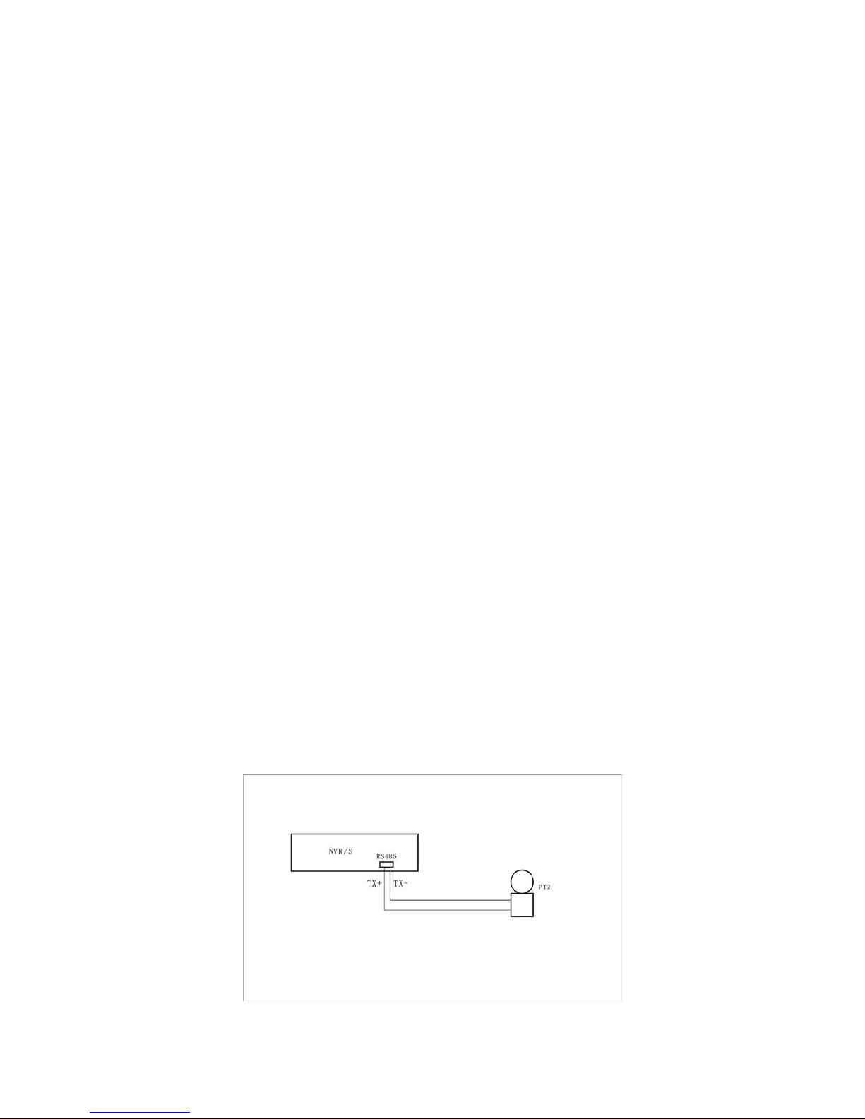
PTZ connection is as following:
About RS-485 pin definition, please refer to the section of “RS-485 connection cable made method”.
12/7/2005https://serenity-support.gviss.com/html/doc/UserManNVR.htm
Page 46
p
p
r
p
Page 46 of 79User Manual NV
R
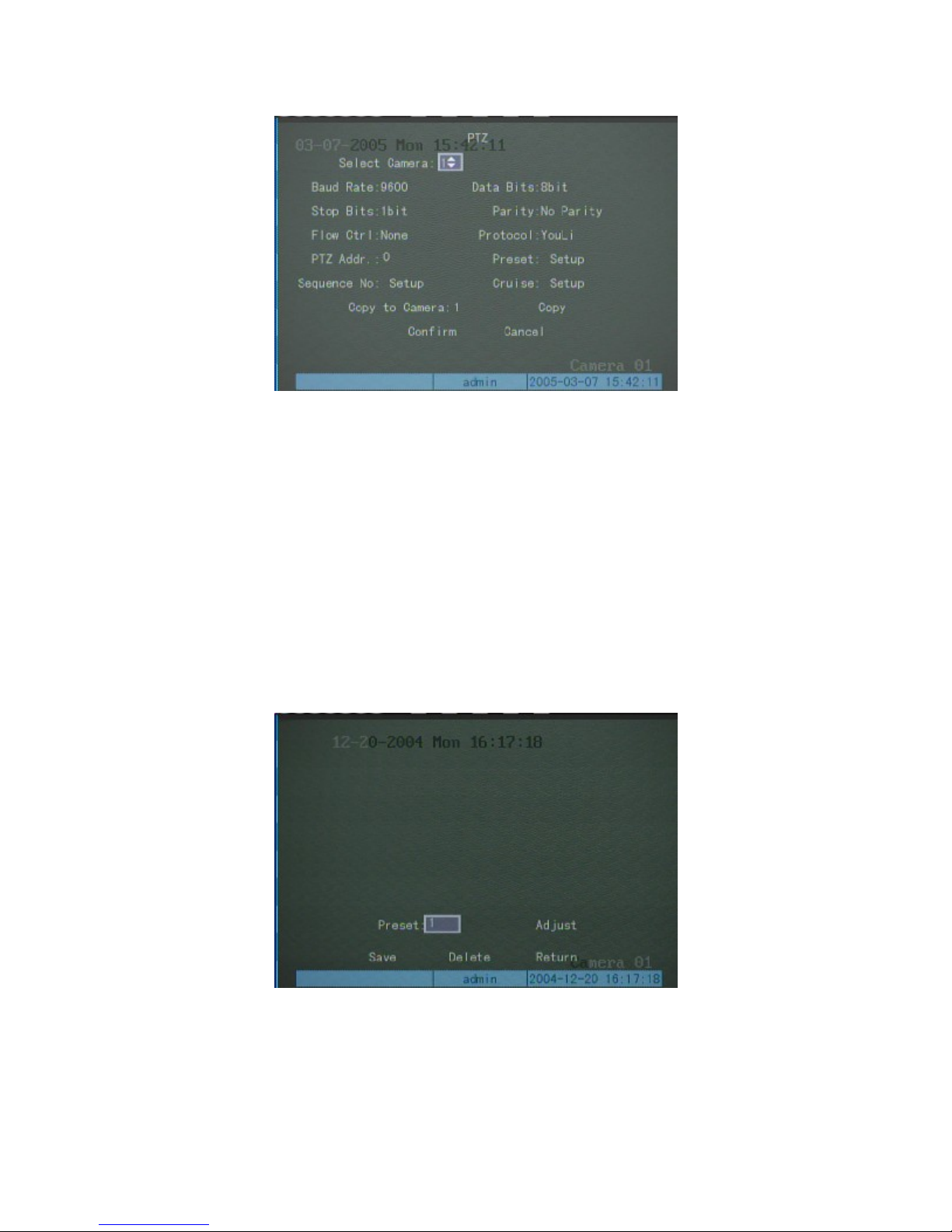
Enter into “PTZ” setup interface.
Select parameters like choose camera no., input baud rate, data bit, stop bit, check, flow control, parameter value
should be consistence with the protocol and the actual setup of the PTZ.
Select PTZ type and input the address. At present the supported PTZ are YouLi, LinLin-1016, LinLin-820, Pelco-
, DM DynaColor, HD600, JC-4116, Pelco-d WX, Pelco-d, VCOM VC-2000, NetStreamer, SAE, SAMSUNG,
KALATEL-KTD-312, CELOTEX, TL Pelco-p, TLHHX-2000, BBV, RM110, KC3360S, ACES, ALSON,
INV3609HD, Howell, Tc Pelco p and Tc Pelco D etc. Along with the software upgrading, there will be more PTZ to be
supported. Please refer to the software.
Preset position, sequence and cruise are set according to the demand. The setup and deletion methods of preset
ositions are described as follows. The setup and deletion methods of sequence and cruise are similar.
Set PTZ Preset
Enter into the “Setup” interface of “Preset”
Input a preset number in preset edit frame; the range is from 1 to 16. Then enter into the “Adjust” interface, to
operate the PTZ to the object position through the direction keys, and adjust the lens through keys like 【ZOOM】,
【FOCUS】,【IRIS】. Press 【Enter】key to return and press “Save” after finishing the adjustment. To define othe
reset positions, repeat the above procedures.
After finishing the setup, execute “Return”. Execute “Confirm” in “PTZ” interface, meantime all the parameters
set will come into effect.
12/7/2005https://serenity-support.gviss.com/html/doc/UserManNVR.htm
Page 47
r
Page 47 of 79User Manual NV
R
Delete PTZ Preset
Enter into “Setup” interface of “Preset”. Input a preset number to be deleted in the preset editing frame, the range
is from 1 to 16, execute “Delete” key. If you want to delete more preset positions, repeat the above procedures.
After finishing the delete, execute “return”. Execute “confirm” in “PTZ” interface to have the delete operation
become effective.
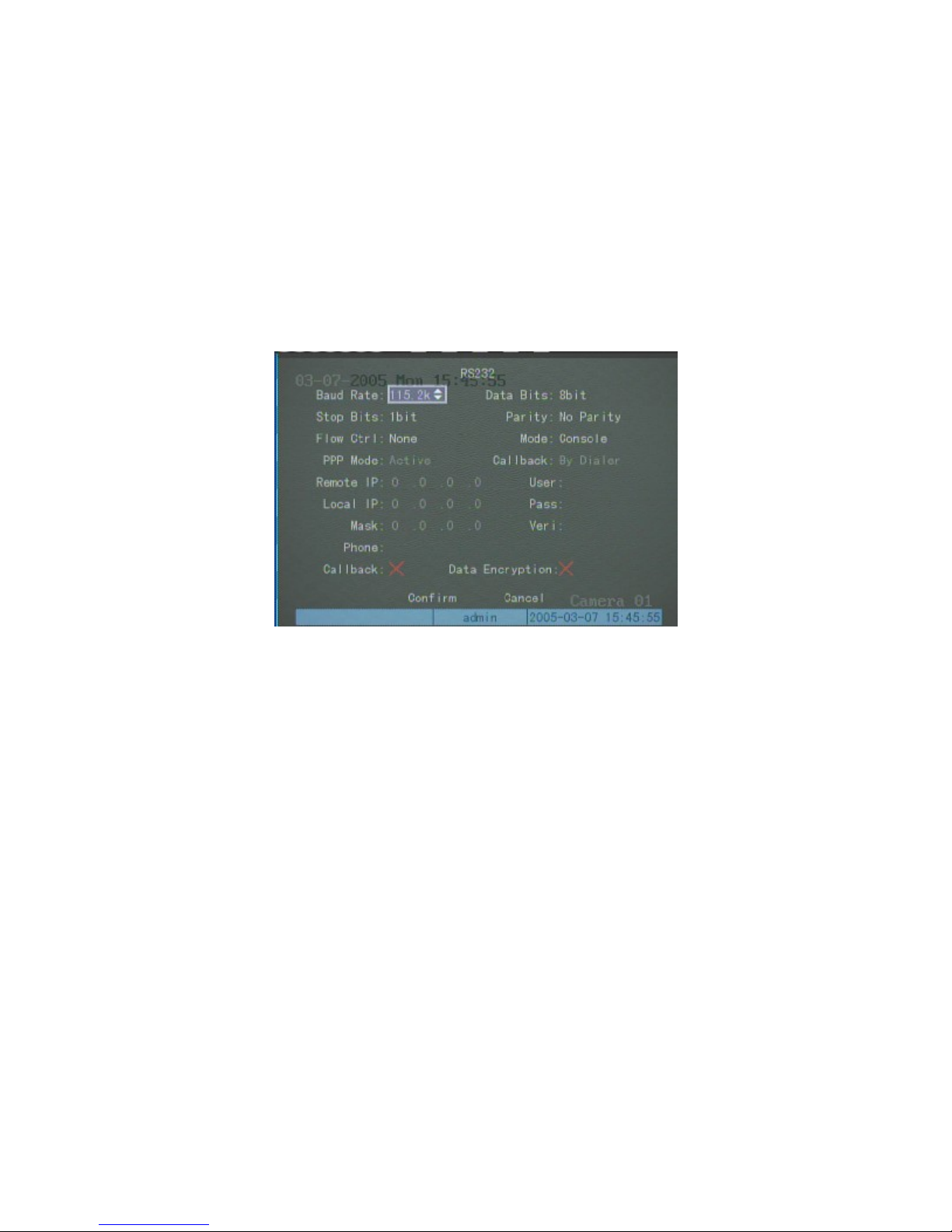
Serial port setup
Enter into “Serial port setup” menu.
Select baud rate, data bit, stop bit, parity and flow control - all the parameters should be consistent with the device
linked.
Select serial port type; options are console, PPP, serial port directly connection, transparent channel.
If “PPP” or “serial port directly connection” is chosen, you need to set PPP mode (active/passive), back dialup
mode (assigned by dialer/preset back dial no.), respectively, then to input the parameters like remote IP address, local
IP address, mask, user’s name, password and verification, telephone number. You should confirm whether it needs to
dial back or not, and whether the transferred data needs to be encrypted or not.
After finishing the setup, select “Confirm” key to save the parameters. The parameter will come into effect afte
rebooting the device. Select “Cancel” or press 【ESC】 key to reverse the setup and return to the main menu.
Exceptions
The Exceptions event parameters include: hard disk full, hard disk error, illegal access, IP address conflict,
network cable not work.
Enter into “Exceptions” setup interface.
12/7/2005https://serenity-support.gviss.com/html/doc/UserManNVR.htm
Page 48
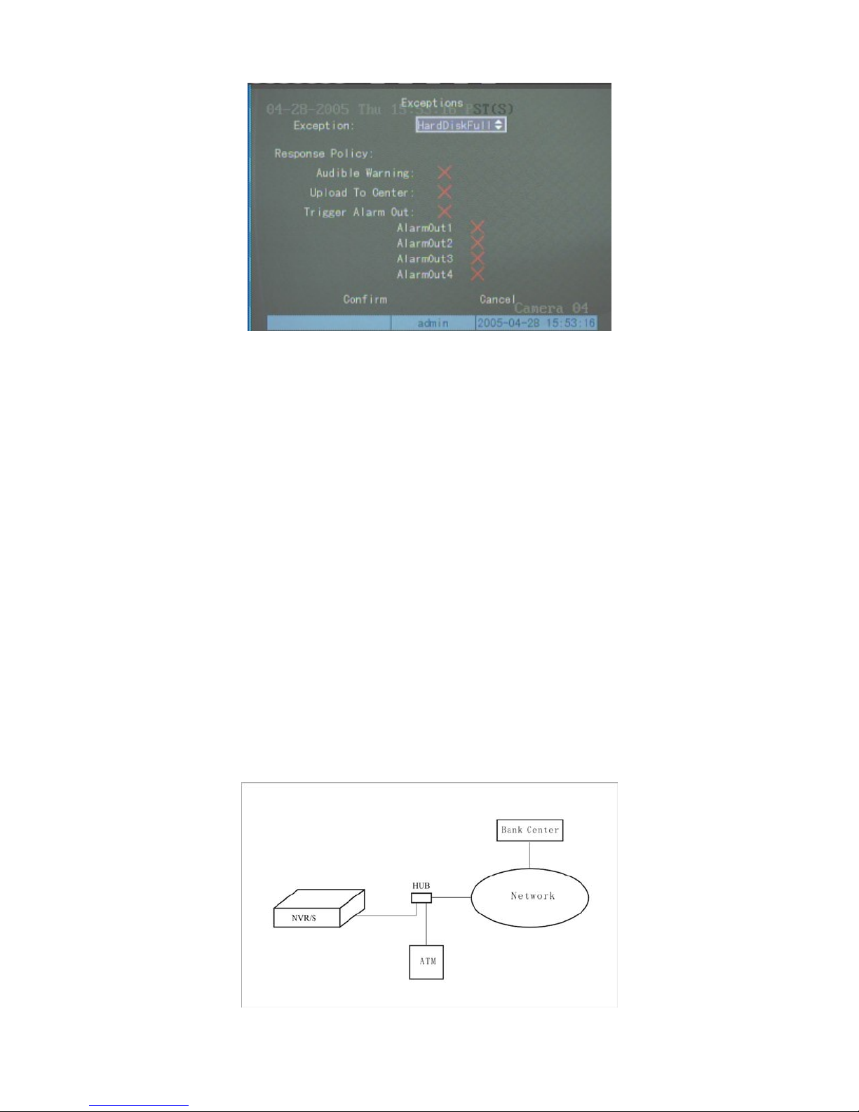
Page 48 of 79User Manual NV
R
Choose one or more handle methods.
After finishing the setup, execute “confirm” to save the parameter and
reverse the current setup.
activate it by rebooting.
Press “Cancel” to
Transaction Information
The device can actively obtain or passively receive the information from other device linked through network or
serial port, and this information can be added, uploaded or processed. The function is mostly used for ATM or POS.
The following description indicates how to carry out relevant parameter setting according to different links to ATM
machine.
FUJITSU, Hitachi, SMI, BULL,Yihua , Lide , Guangdian Yuntong, Mini-Banl, Guangli, Eastcom, Chentong, Nantian,
Xiaoxing, Guangzhou Yuyin, Qinghu Taili etc, among them NCR, FUJITSU, Guandian Yuntong are realized. The
transaction includes inquiry, withdraw, deposit, password modification and money transfer etc.
1. Network Sniff: to obtain the transaction information such as credit card number etc. actively through network.
The network connection is as following:
ATM types supported currently including NCR, DIEBOLD, WINCOR-NIXDORF, Siemens, OVLIVETTI,
Enter into “Transaction Information” menu.
12/7/2005https://serenity-support.gviss.com/html/doc/UserManNVR.htm
Page 49
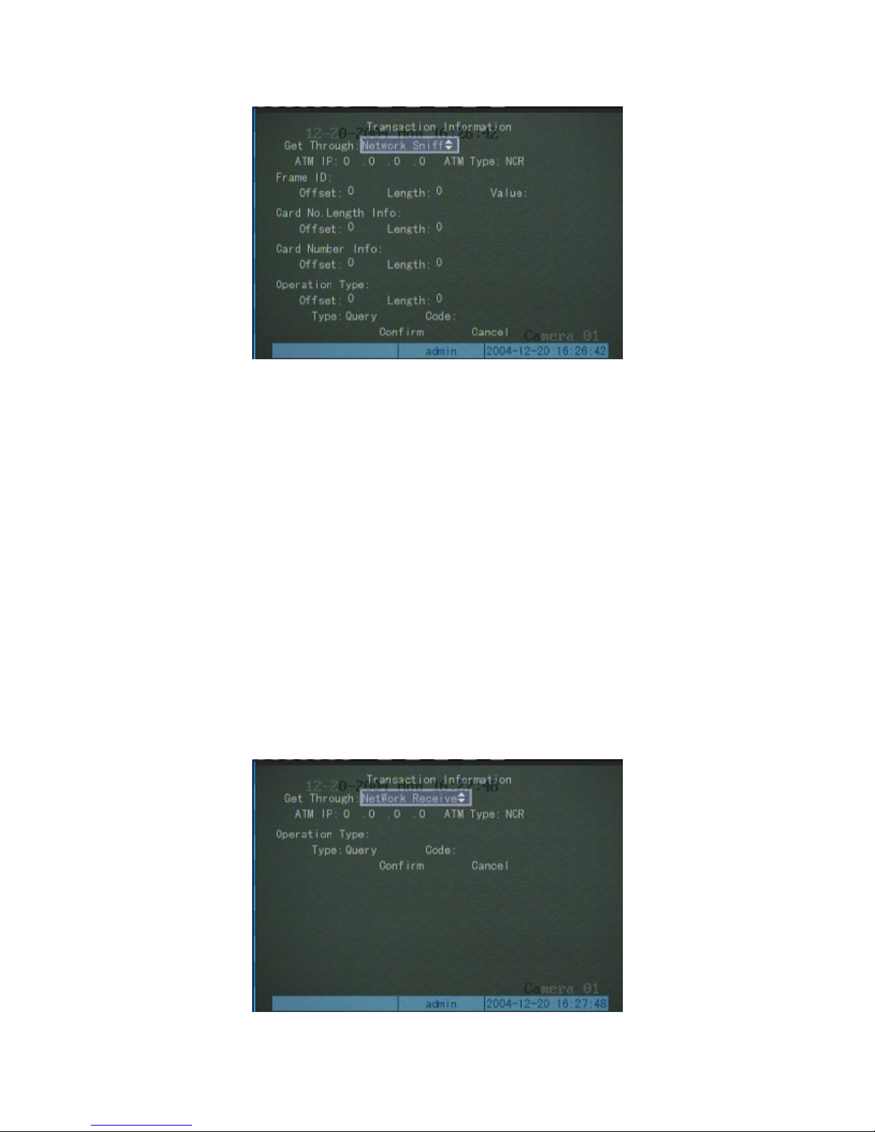
Page 49 of 79User Manual NV
R
In the correspond menu as following:
Message needed to be set:
IP address of ATM/POS
Type of ATM/POS
Start & end position, length and the content of data file
Start & end position and length of card number
Start & end position and length of transaction type
Transaction type and code
When the ATM machine is sending transaction information to bank center, the device will capture the package
through network, and analyses the data according to the format. The device will overlay the correspond text on the
compression image.
2. Network receive, passive receive data sent by ATM/POS through network.
Message needed to be set:
IP address of ATM/POS
The type of ATM/POS
Transaction type and code
In this case, you must develop the software which is run in the ATM machine. The software will send the
12/7/2005https://serenity-support.gviss.com/html/doc/UserManNVR.htm
Page 50
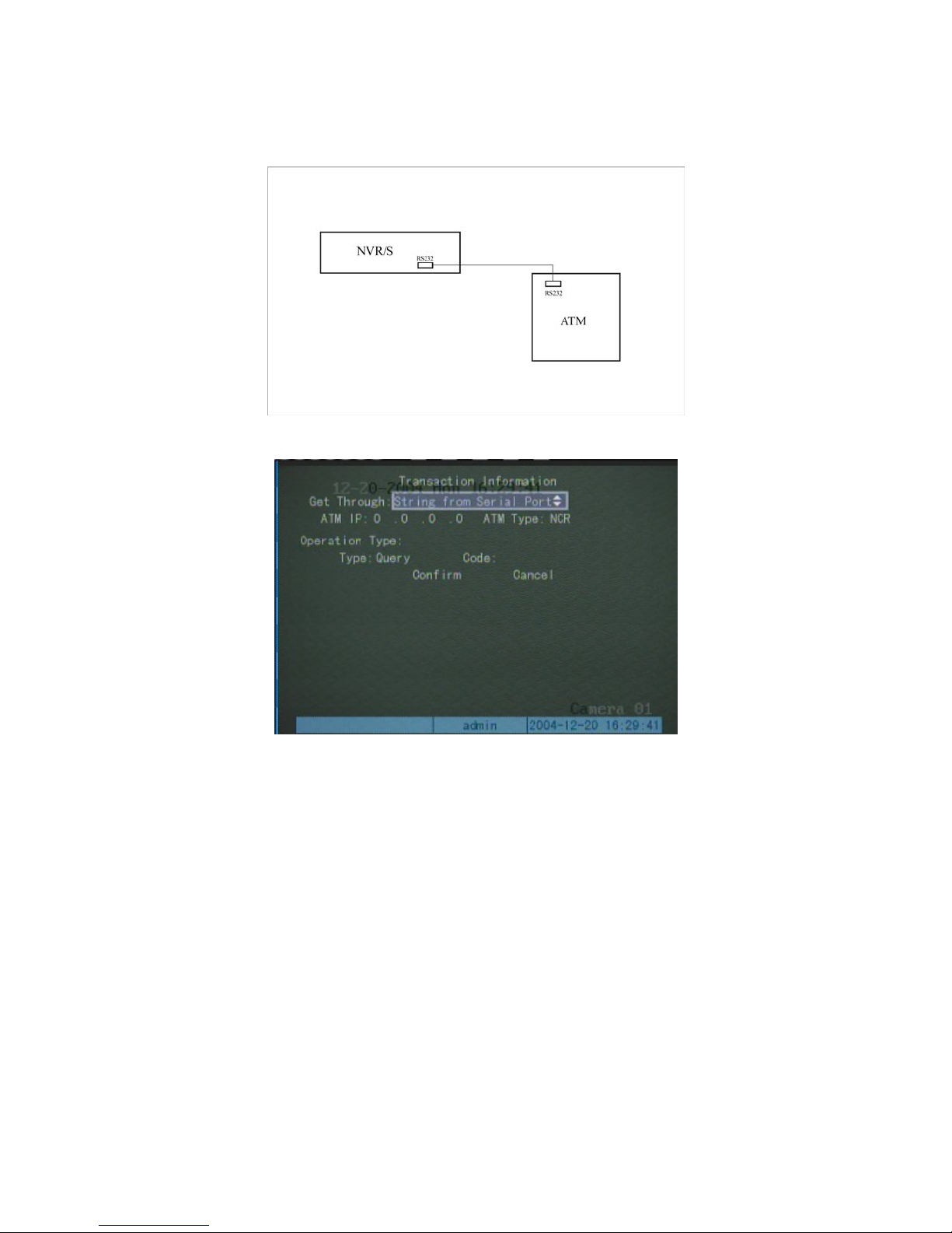
p
Page 50 of 79User Manual NV
R
transaction information directly to our device based on our data format.
3. Receive data sent by ATM/POS through serial ports
In this case, the connection is as following:
In the correspond menu as following:
Message needed to be set:
The type of ATM/POS
Transaction type and code
In the case, you must set the RS-232 of NVR as transparent channel mode, please refer to RS-232 setup menu. A
software must be run in the ATM machine, and send the credit card number, transaction code to NVR through RS-232
ort when necessary.
4. Receive the command sent by ATM/POS through serial ports.
The message needed to be set:
The type of ATM/POS machine
Transaction type and code
12/7/2005https://serenity-support.gviss.com/html/doc/UserManNVR.htm
Page 51
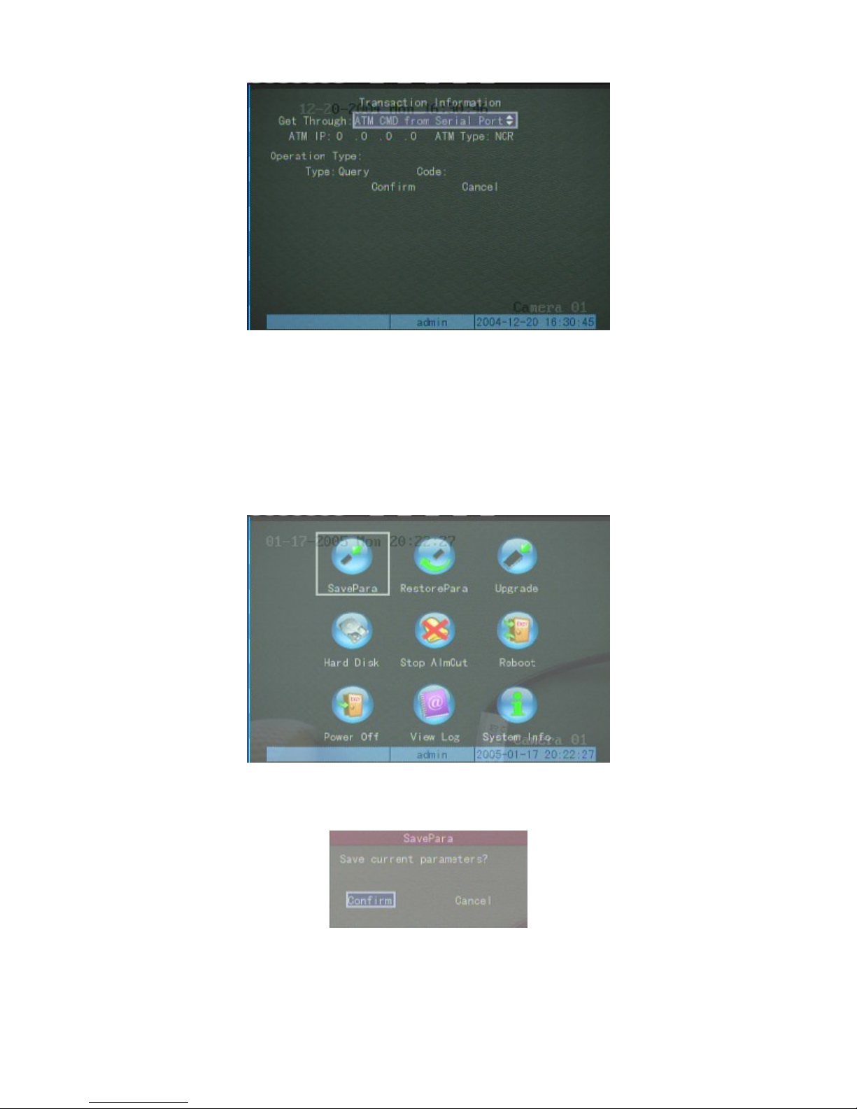
Page 51 of 79User Manual NV
R
Also, one software must be run in ATM machine, and send command to NVR through RS-232 port when
necessary.
Utilities
Enter into “Utilities” interface to start the following operation:
Save the parameters
Save the parameters to the FLASH ROM of the NVR, preparing for future use when rebooting the device.
Restore to factory configuration
Device’s working parameters will be restored to the default factory parameters.
12/7/2005https://serenity-support.gviss.com/html/doc/UserManNVR.htm
Page 52
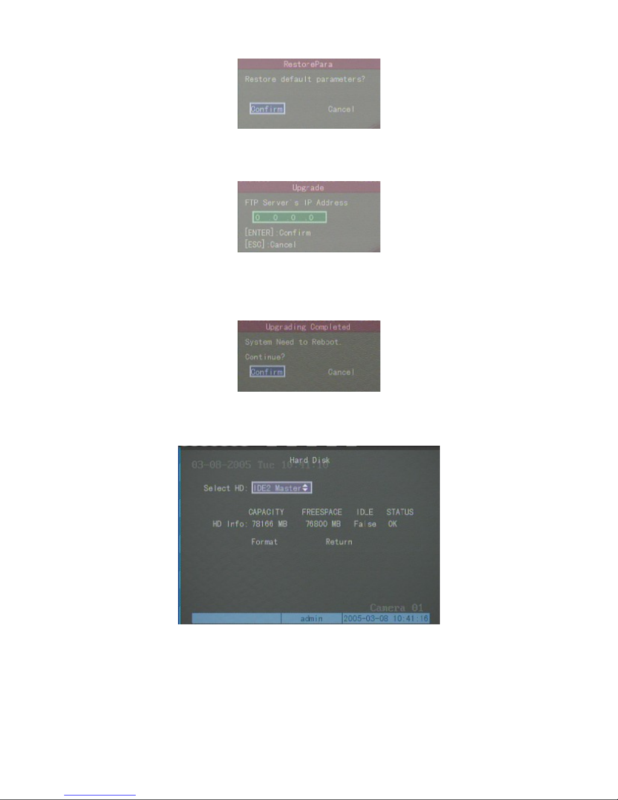
Page 52 of 79User Manual NV
R
Upgrade
upgrade, system will prompt a message dialog.
Hard disk management
This menu will upgrade the NVR’s firmware from the host.
Input the host IP address which has configured FTP server program, press 【Enter
Reboot after successfully upgrading, the system will use the new firmware.
】
to confirm, system begins to
Check the assigned hard disk current status
The capacity of hard disk.
Format the assigned hard disk
Before formatting stop all recording. After formatting, you must reboot the device or the device will not work
normally.
12/7/2005https://serenity-support.gviss.com/html/doc/UserManNVR.htm
Page 53
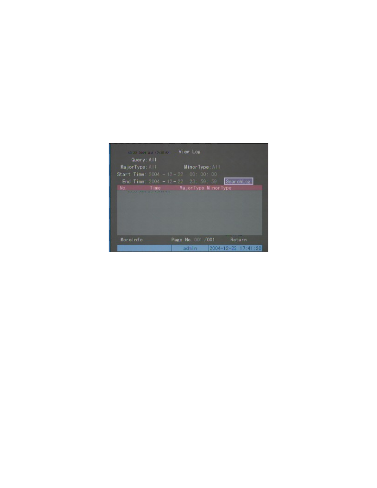
Page 53 of 79User Manual NV
R
Clear alarm
Clear alarm output
Reboot
Reboot the NVR
Shut down
Shut down NVR
View Log
To review the log records enter into “View Log” menu interface, press【Enter】key in front panel directly; all log
information in NVR will be listed in log dialog. If inquiring according to the assigned condition, refer to the following
operations (according to type, time, type &time three mode respectively).
According to type:
To inquire the log information of assigned type.
Type is divided into “Major type” and “Minor type”, major type includes operation, alarm, and exception type log.
Operation log includes local operation and remote operation. Local operation includes Start, Shut down, illegal
shut down, local login, local log-out, local playback file, local play according to time, local boot record, local stop
record, local PTZ control, local preview, local configure time, local upgrade; remote operation includes remote login,
remote log-out, remote boot record, remote stop record, establish transparent channel, disconnect transparent channel,
remote get parameter, remote configuration, remote get status, remote set alarm, remote remove alarm, remote reboot,
start voice dialogue, end voice dialogue, remote upgrading, remote file playback, remote playback according to time,
remote PTZ control.
Alarm Log includes alarm input, alarm output, start motion detection, end motion detection, start mask alarm, end
mask alarm.
Exception event Log including signal lost, illegal access, hard disk error, hard disk full, IP conflict, DCD lost.
The following step is take inquiry “alarm” type as example.
Step one: Select the inquiry type as “according to type”, meantime to activate the “Major type” and “Minor type”.
Step two: Select “alarm” in major type, in “Minor type” you can choose one among “all” “alarm input”, “alarm
output”, “start motion detection”, “end motion detection”, “start mask alarm”, and “end mask alarm” etc.
12/7/2005https://serenity-support.gviss.com/html/doc/UserManNVR.htm
Page 54

k
Page 54 of 79User Manual NV
R
Step three: move the frame to “search log” key, press【Enter】key to begin searching.
Step four: the end of inquiry, log list will list alarm log information, including index number, the time recorded,
major type, minor type, panel operator, network operator, remote host, parameter type, channel number, hard dis
number, alarm input, alarm output, etc. You can use the “more information” key to turn over the screen to check, and
“select page” to turn over the pages.
Step 5: select “return” key to return back to the previous menu.
According to time
To review all the types log information in the assigned time period:
Step one: select the inquiry option as “according to time to activate “start time” and “end time” editing frame.
Step two: input the start time and end time according to the hint format (year-month-date hour: minute: second).
Step three: move the frame to “search log” key, press【Enter】 key to search.
Step four: the end of search, log list will list alarm log information including serial no., time recorded, major type,
minor type, panel operator, network operator, remote host, parameter type, channel no., hard disk no., alarm input,
alarm output, more “more information” key to turn the screen, and “select page” to turn over the pages.
Step five: select “return” key to turn to the previous menu interface.
According to type & time
To check certain type in the assigned time period (take “operation” type as example) Log information, refer to the
following steps:
Step one: select check option as “according to type and time” to activate “major type” and “minor type” at the
same time, and “start time” and “end time” editing frame.
Step two: select “operation” in major type, can choose any option in the minor type.
Step three: input the start, end time according the hint format (year-month- date hour: minute: second).
Step four: move the frame to “search log” key, press【Enter】 key to search.
Step five: end of search, log list will list alarm log information including serial number, time recorded, major type,
minor type, panel operator, network operator, remote host, parameter type, channel number, hard disk number, alarm
input and alarm output, user “more information” key to turn the screen, use “choose page” to turn over the page.
12/7/2005https://serenity-support.gviss.com/html/doc/UserManNVR.htm
Page 55

R
Step six: select “return” to return to the previous menu interface.
Check system information
Page 55 of 79User Manual NV
12/7/2005https://serenity-support.gviss.com/html/doc/UserManNVR.htm
Page 56

Page 56 of 79User Manual NV
R
Network Operation
PPPoE dialup
Before using this function, plea se make sure the NVR has PPPoE dialup function ality.
Create Connection by Using PPPoE
In “Network” menu, select “PPPoE”. Input PPPoE user name and password provided by ISP (Internet Service
Provider) and verify them. Reboot the device after saving. The NVR will create network connection automatically in
PPPoE mode after startup. After successful connection, IP address in “Network Setup” will be modified into an
acquired WAN dynamic IP address.
Access through Client software when using PPPoE
Access directly through IP address of current device.
After successful PPPoE dialup, view “IP” in “Network Setup”. Acquire the device current IP address. Then client-
end will access NVR by using this IP address.
Access through domain name analysis server
The adoption of this mode requires a PC that has a fixed IP address located on Internet, and the domain name
analysis server software must be running on this PC (the domain naming server “DNS”).
Operation: In “Network” setup menu, select “PPPoE”. Input PPPoE user name and password provided by ISP
(Internet Service Provider) and verify them. Input IP address of PC as analysis server in “DNS Address”. Reboot the
device after saving. Then in “Local Configuration” of client-end program, input the name of NVR to be accessed in
“Monitor Server Name”. Start analysis server. Input IP address of analysis server. Input monitoring Channel to be
accessed, and user name and password. Save the entries and you can access the NVR at this time.
Working theory: DVR adopts PPPoE mode to establish the network connection, it will modify IP address in
“network” to be IP address of the internet, and will send the name and the current IP address to the analysis server.
When client-end software wants to access DVR, it should connect with the analysis server PC, telling the analysis
server the name or the serial number of NVR to be accessed. The analysis server will search all the NVR registered to
find the matched NVR and the corresponding Internet IP address, and tell this address to client-end software. The
client-end can access the NVR with the current IP address.
PPP(Modem) passive dialup
12/7/2005https://serenity-support.gviss.com/html/doc/UserManNVR.htm
Page 57
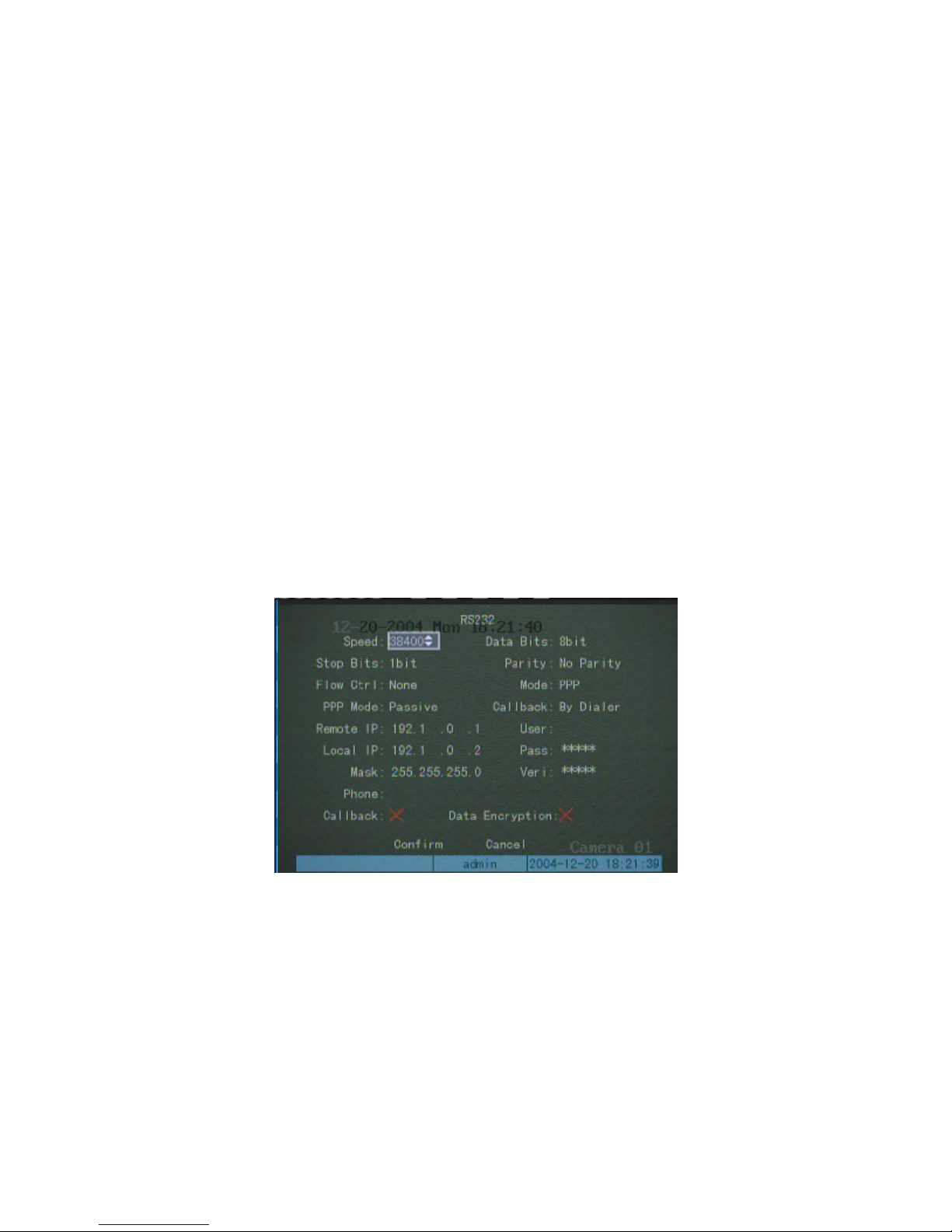
Page 57 of 79User Manual NV
R
Before using this function, please make sure advance that the NVR used support PPP passive dialup
function. Two Modems are needed; one to connect with RS-232 interface through DCE cable, the other to
connect with PC COM port through DCE.
NVR-end setup
1. Setup the RS232 port of NVR:
The parameter value of speed, data bit, stop bit, check, flow control should be consistent with the Modem
default parameter value connected with PC.
Mode ---- PPP
PPP mode ---- passive
Callback ---- by dialer
Remote IP: After successfully PPP dialup, it will assign the designated IP address to PC, e.g. set as 192.1.0.1;
Local IP: After successfully PPP dialup, it will assign the designated IP address to the video recorder, e.g. set as
192.1.0.2。
Mask: 255.255.255.0
The following picture is the corresponding setup of certain Modem.
2. Video signal parameter setup:
Select the channel to carry on the Modem transmission in “record” setup, as follows:
。
Code stream type ---- video stream Max bit rate ---- variable bitrate
bit rate ---- below 64kbps Image quality ---- normal
The video frame rate is confirmed according to resolution. If choose CIF as the resolution, it is recommended
to select frame rate as 1frame or self-adaptable, when choose resolution as QCIF, it is recommend to select frame
as 4 frame. Resolution CIF has a better definition, while QCIF resolution has a shorter delay. User can adjust the
bitrate, resolution and video frame rate according to the actual application.
The set effect is as follows:
12/7/2005https://serenity-support.gviss.com/html/doc/UserManNVR.htm
Page 58
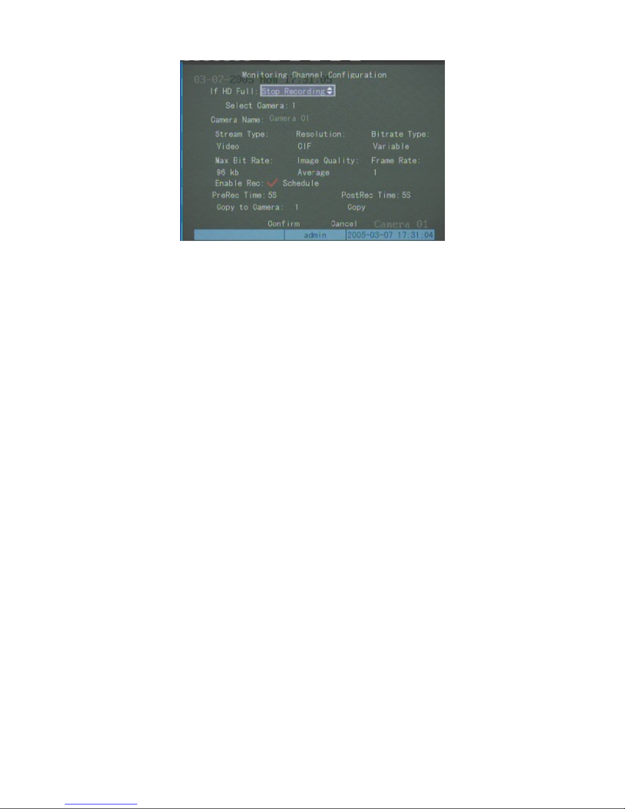
p
Page 58 of 79User Manual NV
R
3. Save the parameter setup of the video recorder, reboot the video recorder to make the parameter into effect.
4. Setup NVR-end Modem
Need to restore the defaulted parameter, then to set as response end.
Connect Modem with PC through DCE cable, set he baud rate of the serial port software (e.g. NetTerm) to be
consistence with Modem defaulted baud rate of server-end. Enter into connection status, input AT command as
follows:
5. Connect Modem with the RS-232 serial port of NVR through DCE cable.
AT&F ---- restore defaulted parameter (normally, Modem is hard flow control)
AT&S0=1 ---- set Modem as response end
ATE0 ---- do not respond to the input letters
ATQ1 ---- to carry on the command, do not respond to the input letters.
AT&W&W1 ---- save the parameters.
PC-end setup
1. Set PC-end Modem
Need to restore to defaulted parameter.
Connect Modem with PC through DCE cable, set the baud rate of the serial ports software (e.g. NetTerm) to be
consistent with the Modem defaulted baud rate in PC-end. Enter into connection status, input AT command as follows:
AT&F ---- restore to defaulted parameter (Generally, Modem is hard flow control)
AT&W&W1 ---- save the parameter.
2. Open “Network and Dial-up Connections” in control panel, then press “New Connection…”, select “Dial-up to
rivate network” according to the guide. Select the corresponding MODEM, input the telephone number to be dialed in
the next step, finish it according to the guide. You will then find a new program named “Dial-up Connection” in
“Network and Dial-up Connections” folder.
Setup should be specially pay attention to:
12/7/2005https://serenity-support.gviss.com/html/doc/UserManNVR.htm
Page 59
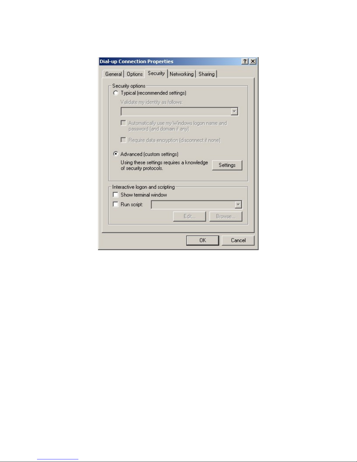
p
Page 59 of 79User Manual NV
R
Open the properties of the new-established dialup program, select “Advanced”(custom settings) in security option,
ress setup, set it in the popup dialogue box named “Advanced Security Settings” as follows:
12/7/2005https://serenity-support.gviss.com/html/doc/UserManNVR.htm
Page 60

r
Page 60 of 79User Manual NV
R
3. Establish the dialup connection
Select the Modem connected with PC just like the dialup network connection, input the telephone numbe
connected with video recorder’s modem.
4. During the dialup connection, it will give the prompt of “verification of user’s name and password”; after successful
verification the prompt will be “on process of register in PC”. The process is the same as the common dialup
connection.
5 After successful dialup, network will designate the “remote IP” address to PC, e.g. the set 192.1.0.1. User can Ping-
link the assigned IP address through the “Ping” command, and can Ping-link the video recorder. The following picture
shows the effect of PC IP address and Ping-link between PC IP address and video recorder after a successful dialup.
12/7/2005https://serenity-support.gviss.com/html/doc/UserManNVR.htm
Page 61
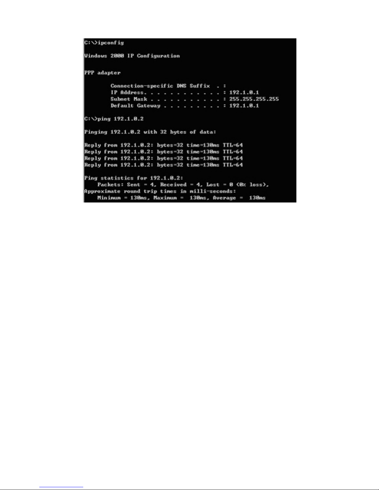
Page 61 of 79User Manual NV
R
6. You can preview the image of 192.1.0.2 by using client-end software.
Serial port directly connected
Before using this function, please make sure tha t th e NVR has the serial port directly connected function.
Connect the RE-232 port in the NVR with COM port in the PC through DCE cable.
Server-end setup
1. RS232 port setup:
Speed ---- 115.2Kbps data bit ---- 8 bit stop bit ---- 1 bit
parity---- no parity flow control ---- soft flow control mode ---- direct
PPP mode ---- passive callback ---- by dialer
Remote IP: after serial port successful connected, it will assign the PC a designated IP address, e.g. set the IP
as 193.1.0.1;
Local IP: after serial port successful connected, it will assign the server an appointed IP address, e.g. set the
IP as 193.1.0.2.
Mask: 255.255.255.0。
Please refer to the following:
12/7/2005https://serenity-support.gviss.com/html/doc/UserManNVR.htm
Page 62
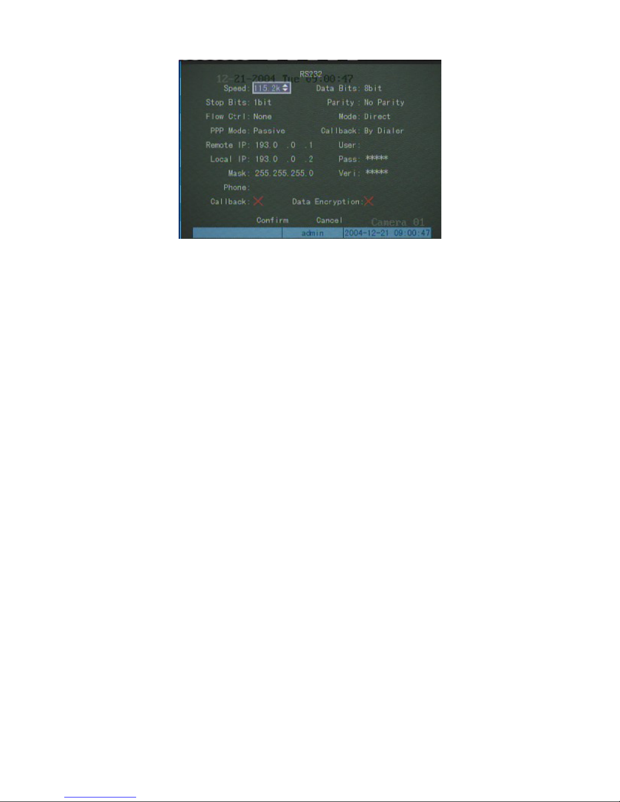
p
Page 62 of 79User Manual NV
R
PC-end setup
1. To establish a direct connection with the PC server:
Open “Network and Dialup Connection” in the control panel, select “New Connection…”, select “Connect
directly to another computer” according to the guide, press the next, select “Guest” in “Host or Guest”, press the next,
select the device as “Communications cable between two computers”, to finish the establishment of directly connection
according to the guide.
2. Configure “Direct Connection”
Open “Network and Dial-up Connections” in the control panel, open the “Direct Connection”, select “General”,
ress the “Configure” in “General” as the fig.
12/7/2005https://serenity-support.gviss.com/html/doc/UserManNVR.htm
Page 63
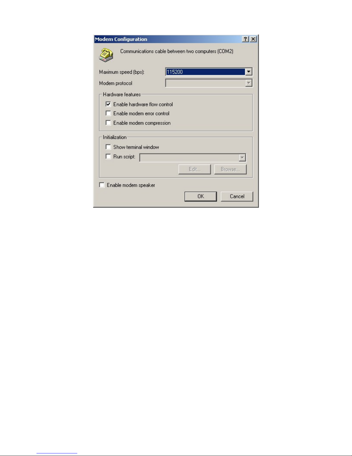
Page 63 of 79User Manual NV
R
3. Connection
The setup of the user’s name and password should be consistence with server-end, save the parameter and begin to
dialup. After a successful dialup, network will appoint the “remote IP” set to PC e.g. 193.0.0.1, and assign “local IP”
address to video recorder, e.g. 193.0.0.2 set. User can use Ping–link the IP address assigned or to link the video server.
At the mean time, you can access the video recorder through client-end software.
12/7/2005https://serenity-support.gviss.com/html/doc/UserManNVR.htm
Page 64

t
p
Page 64 of 79User Manual NV
R
Upgrading NVR Firmware
NVR users may upgrade the firmware of the NVR by using the Upgrade/Download service on the Customer Suppor
Portal – serenity-support.gviss.com.
Simply log on to the Customer Portal and follow the on-screen directions.
Installation Introduction
Notes: Please make sure the NVR’s power is disconnected before connecting with any device.
Install Hard Disk
Installation Hint
Disassembly of the housing and installation of the hard disk must be installed by professionals. Before the work,
lease calculate total capacity of hard disk required by each NVR according to the planned video recording program.
Installation Tool
One cross head screw driver.
Install Hard disk
1. Open the housing.
2. If two hard discs are connected to one ATA hard disk data cable, set the main disk and sub-disk.
3. Unscrew the tray to which the hard disk will be fastened.
4. Screw the hard disk to the support tray.
5. Re-install the support tray back in the NVS.
6. Connect the hard disk data cable (red cable near to the power side).
7. Connect the hard disc power cable.
8. Replace the cover of the housing and fix with screws.
Back Panel Introduction
12/7/2005https://serenity-support.gviss.com/html/doc/UserManNVR.htm
Page 65
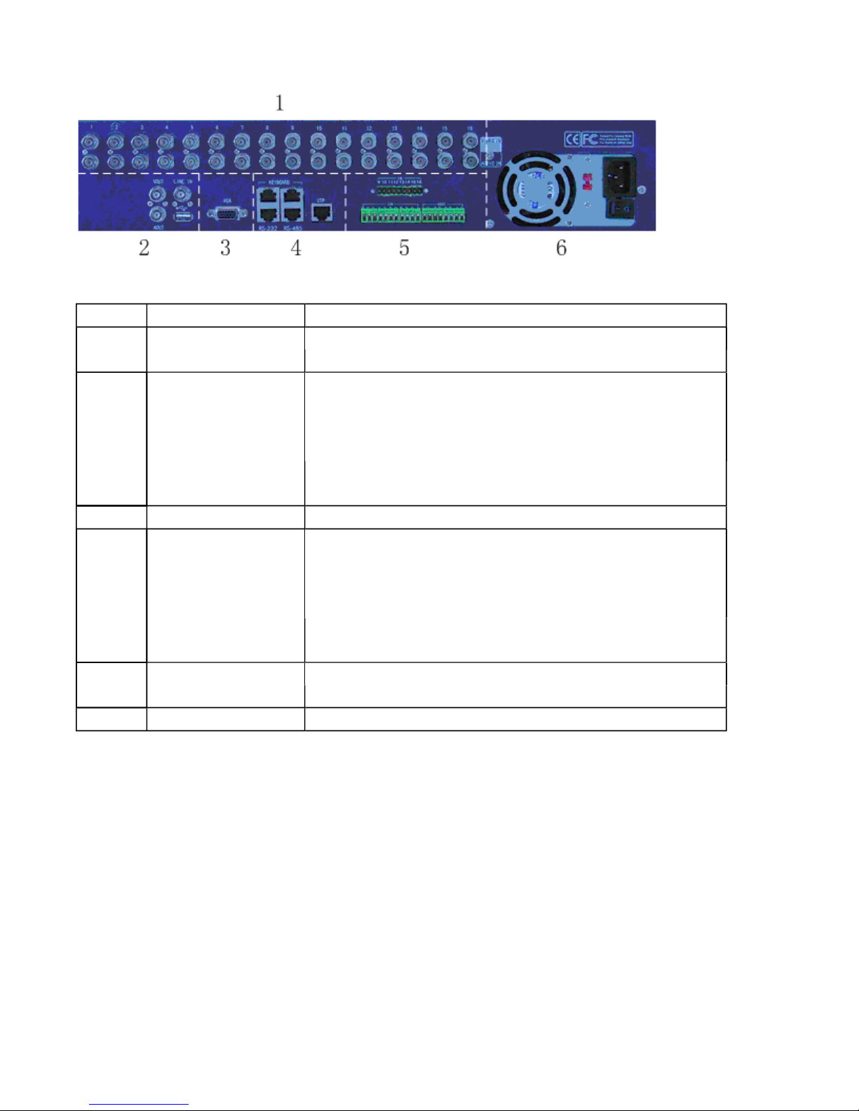
Page 65 of 79User Manual NV
R
Physical interface and the connection Introduction
No.
1
2
3
4
5
6
Video Input
Audio Input
Video Output (BNC)
Audio Output
Voice Input
USB interface
Video output (VGA)
Keyboard interface
RS-232 interface
RS-485 interface
UTP network interface 10/100Mbps self-adaptable Ethernet interface, to connect network
Alarm input
Alarm output
Power
Name
To connect (analog) video input device, standard BNC connector
To connect (analog) audio input device, standard BNC connector
To connect monitor to output analog video signal, standard BNC
connector
To connect (analog) audio output device, standard BNC connector
To connect voice input device (like Mic), standard BNC connector
USB1.1 standard interface to connect USB storage device, used to
backup of the DVR files
To connect video display device, standard VGA interface
2, one to connect (485) to control keyboard, one is used for linking
of DVR, both are RJ45 plug-in
To connect RS-232 standard device (like MODEM), RJ45 plug-in
To connect RS-485 standard device (like PTZ), RJ45 plug-in
device, RJ45 plug-in
8 alarm in, can be enlarged to 16
4 alarm output
Standard ATX power, 220V/110V input power
Description
Alarm input/output connection method
Alarm input interface introduction
12/7/2005https://serenity-support.gviss.com/html/doc/UserManNVR.htm
Page 66
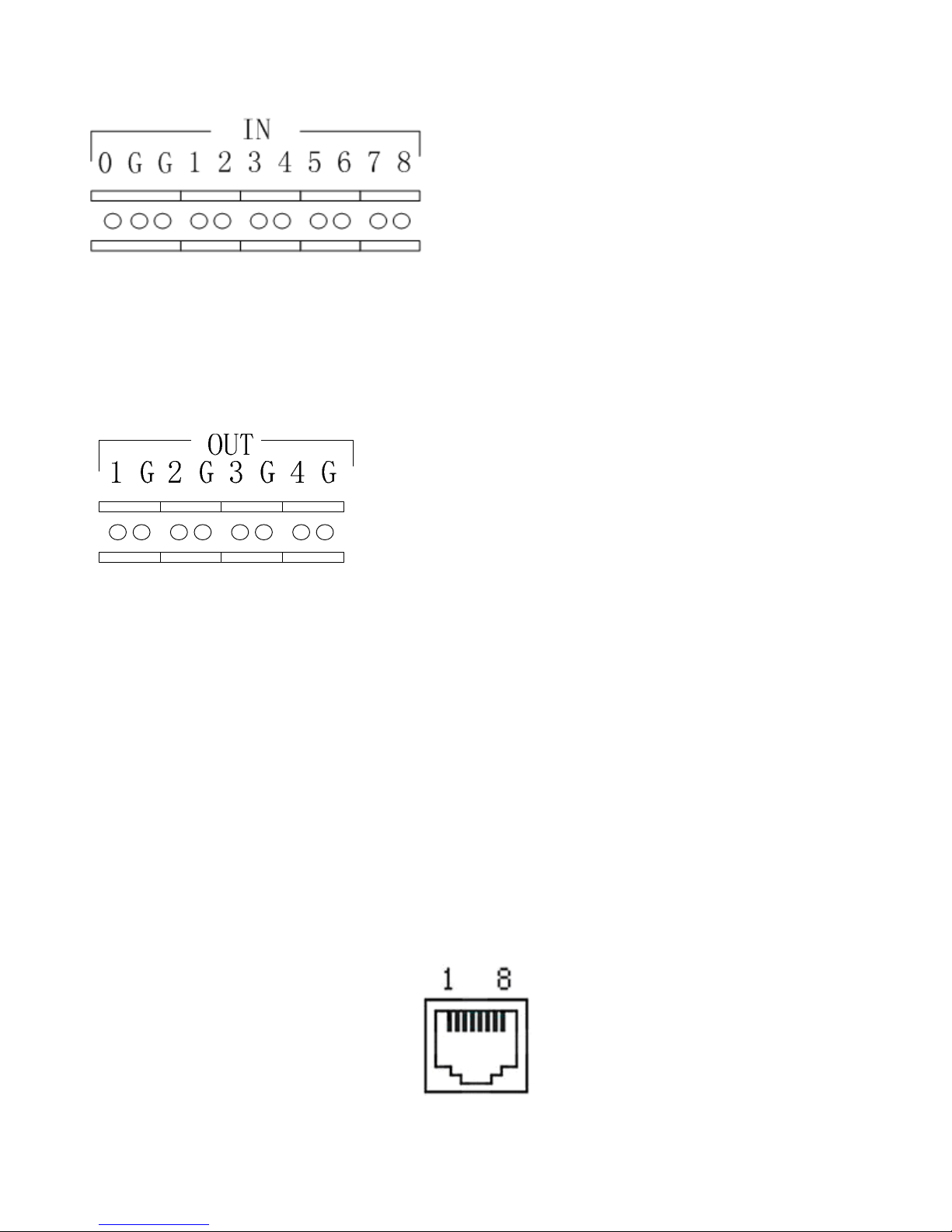
Page 66 of 79User Manual NV
R
G(GND): 2 “Alarm Input” GND port, is communicated inside, shared the GND with every alarm input device.
1-8: to connect with alarm input device, normal open/normal closed electrical method touch off, power range 0~5V.
0: standby
Alarm output interface introduction
G (GND): “Alarm Output” GND port, every output port and the corresponding alarm output device shared the GND.
1-4: can connect 4 alarm output devices respectively.
If there is an alarm, 1/2/3/4 will connect with the corresponding GND, to touch off lamp/light/sound. There are
four leap lines, they are JJ1, JJ2, JJ3, and JJ4, which can give the option to the alarm output method. It is closed when
ex-factory. The above introduction is to this output method. If to disconnect the leap line, the 4 alarm outputs are just
likes 4 switches. If an alarm occurs the corresponding switch will go to the on position.
It is suggested the alarm output switch is used between 12V power voltage, 1A electricity current range.
RS-485 connect cable made method
Material and tool
One twist cable (8 pins), one standard RJ45 connector, one tool specially for RJ45
RJ45 introduction
Pin Definition
12/7/2005https://serenity-support.gviss.com/html/doc/UserManNVR.htm
Page 67
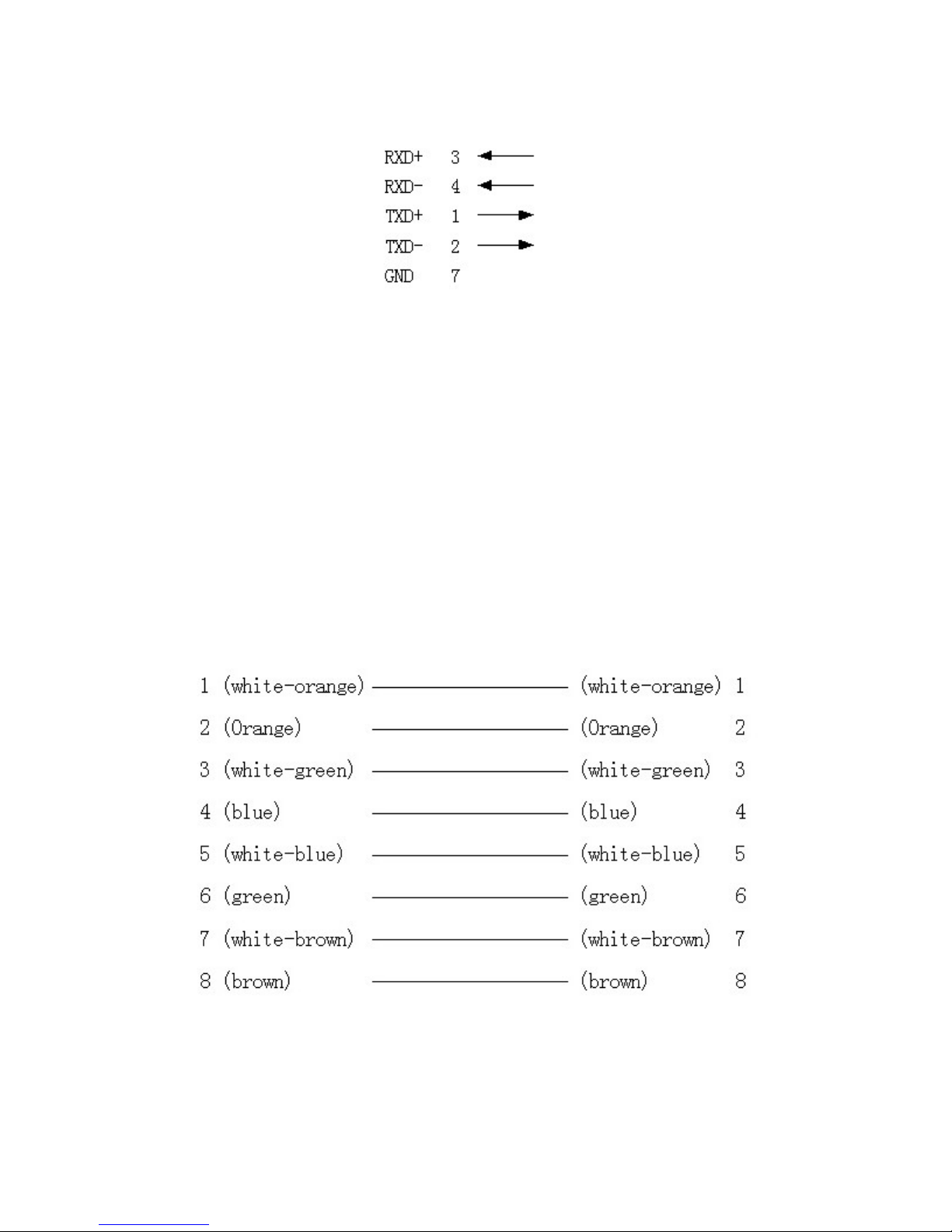
k
Page 67 of 79User Manual NV
R
To make the connect cable according the follows. As to left point of RJ45 head, 1, 2 cable is the anode and
cathode line for sending, 3, 4 cable is the anode and cathode line for receiving, 7 is the shared grounding line:
Pin definition for Standard RS-485 serial port RJ45 plug-in
UTP network connect cable made method
Material and tool
One twist cable (8 pin, the length can be defined as to the actual demand, but must be within 100m), 2 standard RJ45
head, one tool for RJ45.
Suggestion: have a network cable test tool to test each cable made.
Pin definition
To make the network cable according the actual situation, there are two options:
(1)use the following method to make the network cable when NVR is connected with HUB or the networ
switcher.
(2)using the following method to make the twisted network cable when NVR is directly connected with client-
end PC.
The corresponding relationship of the direct cable
12/7/2005https://serenity-support.gviss.com/html/doc/UserManNVR.htm
Page 68
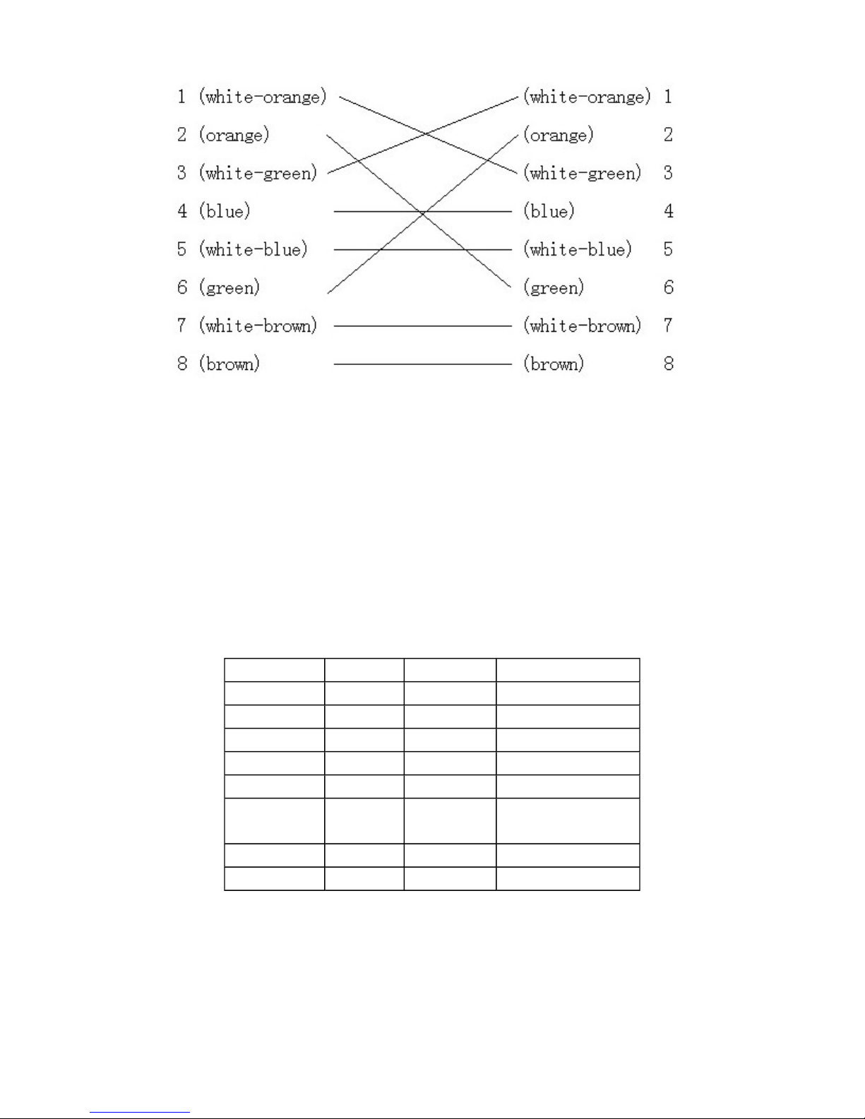
Page 68 of 79User Manual NV
R
The corresponding relationship of twisted cable
RS-232 connect cable
Material and tool
One twisted cable (8 pins), one standard RJ45 head, one or more DB25 or DB9 plug-in, a tool for RJ45, one
electric iron, and some soldering tin.
Pin definition
To make the RJ45 according to the following pin definition; I means DVR input, O means NVR output.
Pin No.
1
2
3
4
5
6
7
8
Name
DCD
RxD
TxD
CTS
RTS
DTR
GND
Empty
I/O
O
O
O
—
I
I
I
Discription
Carrier Detect
Receive data
transmit
Clear data
Request to send
Terminal device is
GND
—
ready
According to demand, the following three situations is considered to make the serial port plug-in according to the
corresponding relationship of the pin definition.
(1)
when the serial port of the NVR is connected with the DTE device with DB25 plug-in (terminal like
computer, annunciator, door access etc), the corrresponding relationship is as follows:
12/7/2005https://serenity-support.gviss.com/html/doc/UserManNVR.htm
Page 69
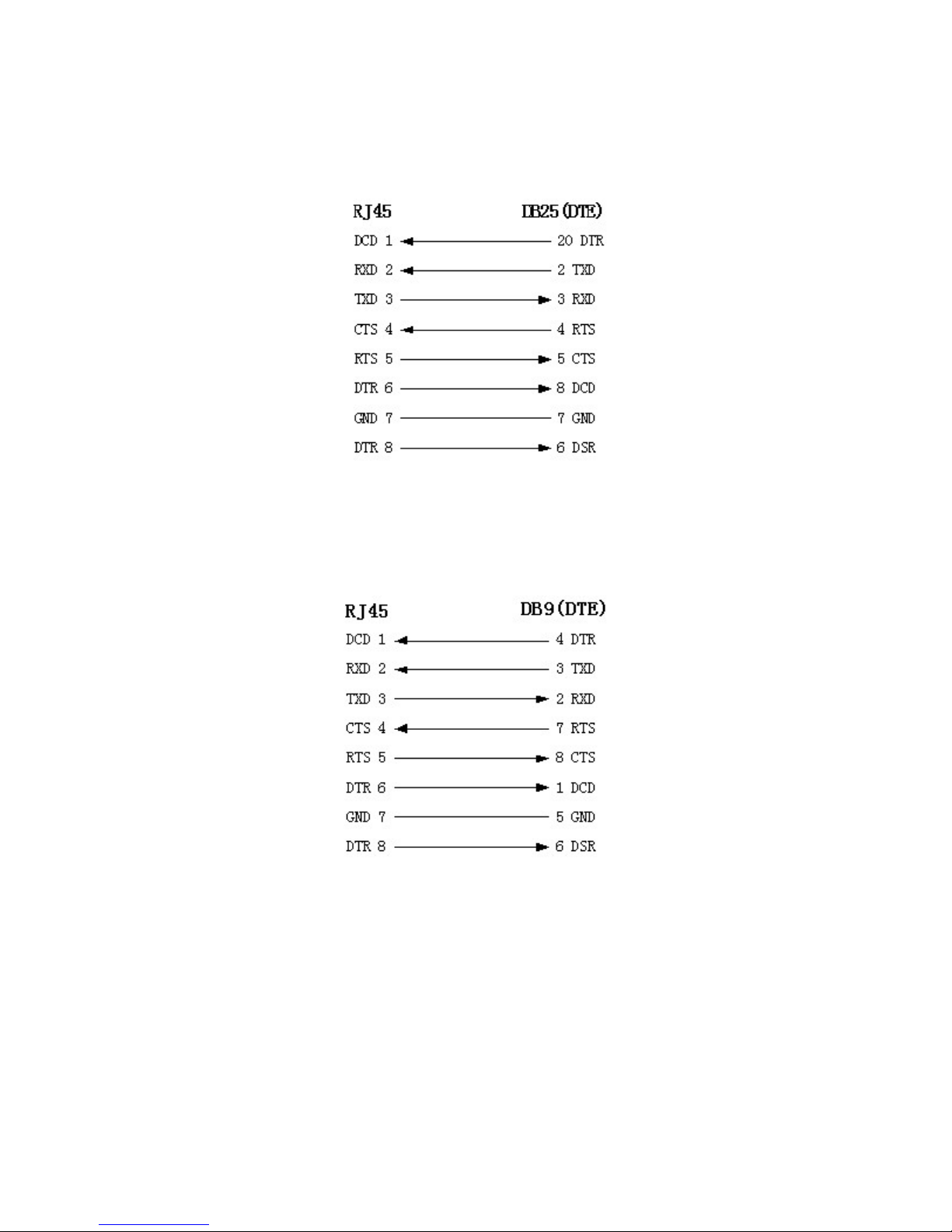
Page 69 of 79User Manual NV
R
The connect fig for RJ45 and DB25 (DTE)
(2)
when the serial port of the NVR is connected with DTE device with DB9 plug-in, the corresponding
relationship is as follows:
The connect fig for RJ45 and DB19
25-pin to 9-pin converter internal connection is like the follows:
12/7/2005https://serenity-support.gviss.com/html/doc/UserManNVR.htm
Page 70

Page 70 of 79User Manual NV
R
The connect fig. for DB25 and DB9
(3)serial port of NVR is connected with DCE device (like MODEM), one end of the cable is 8-pin RJ45 plug-
in, the other end is DB25 pin plug-in, the corresponding relationship is as follows:
The connect fig. for RJ45 and DB25(DCE)
12/7/2005https://serenity-support.gviss.com/html/doc/UserManNVR.htm
Page 71

Specifications
R
Page 71 of 79User Manual NV
Video Compression Standard
Preview Resolution
Playback Resolution
Video Input
Video Output
Video Frame Rate
Stream Type
Video Output bitrate
Audio Input
Audio Output
Audio Compression Standard
Audio Compression Code Rate 16Kbps
Audio Dialogue Input
Communication Interface
Keyboard Interface
Link Interface
Hard disk IDE interface
USB Interface
VGA Interface
Alarm Input
Alarm Output
Power Supply
Power Consumption
Working Temperature
Working Humidity
Size
Weight
H.264
PAL: 704*576
NTSC: 704*480
PAL: 176*144, 352*288, 704*288, 528*384, 704*576
NTSC: 176*120, 352*240, 704*240, 528*320, 704*480
1-16 channel (NTSC, PAL format system auto recognition)
BNC (Electrical Level: 1.0Vp-p, resistance: 75Ω)
1 channel (NTSC, PAL optional)
BNC (Electrical Level: 1.0Vp-p, Resistance: 75Ω)
PAL: 1/16—25 frame/ second
NTSC: 1/16—30 frame/second
Can select single video stream or composite stream
16K~2M can be adjusted or self-defined. (unit: bps)
1-16 channel, BNC (Linear Electrical Level, Resistance: 1kΩ)
1 channel, BNC (Linear Electrical Level, Resistance: 600Ω)
OggVorbis
1 channel, BNC (Linear Electrical Level, Resistance: 1kΩ)
1 RJ45 10M/100M Self-adaptable Ethernet Interface
1 RS232 interface,
1 RS485 interface
1
1
4, support 8 IDE hard disk, max 200GB capacity for each
hard disk, max 8 IDE hard disk installed inside
1, protocol: USB1.1. Support USB flash memory, USB
portable hard disk, USB CDRW
1, resolution: 800×600/60Hz, 800×600/75Hz, 1024×
768/60Hz, 1024×768/75Hz
8/16 channel
4 channel
90--135VAC or 180--265VAC, 47--63 HZ
No more than 44W (not including hard disk)
-10℃--+50
10%--90%
19” Standard (450mm*450mm*95mm)
8Kg(Not including hard disk)
℃
12/7/2005https://serenity-support.gviss.com/html/doc/UserManNVR.htm
Page 72

R
Frequently Asked Questions
Page 72 of 79User Manual NV
Failure
After plugging in power and turning on switch, “POWER”
light in front Panel does not turn on, and fan does not
work.
After plugging in power, turning on the power switch,
“
POWE
does not work.
R” light in front panel turn to green while fan
After plugging in power, turning on switch, “POWER”
light turn to green, the indicator lights in the panel turn on
at the same time, but fan does not work.
NVR continuously reboots after start up, and makes a
sound like “di” every 10 seconds.
There are no images in the monitor connected in VOUT
after startup of the NVR.
Cannot find the hard disk after startup
RS-232 serir there is no response when press the keys in
the keyboard even the RS-232 serial port output is
normal.
The PTZ connected with RS-484 interface in DVR cannot
be controlled.
There is no video audio network transmission at the client
end.
Possible reasons
1)
power cable faulty
2)
switch faulty
front panel cable faulty
1)
Front panel faulty
2)
The ATX plug in main board is not well
plugged in.
1)
2)
3)
1)
2)
3)
1)
2)
3)
1)
2)
3)
1)
2)
3)
1)
upgrade the wrong firmware
compression board has a problem
main board has a problem
The cable connected with the monitor is
faulty
Interface board in NVR has problem
Main board in NVR has problem
Hard disk cable is faulty
The power cable of hard disk is not
connected
Hard disk is faulty
RS-232 serial port cable is faulty
Serial port in PC is faulty
RS-232 serial port in main board is faulty
RS-485 interface cable is not well
connected
The PTZ decoder type is not well
matched
RS-485 interface in main board has a
problem
One or even more than one options like
IP address, port number, user’s name and
password in the “Local setup” in the
client-end interface are not correct
Network cable is not good
2)
12/7/2005https://serenity-support.gviss.com/html/doc/UserManNVR.htm
Page 73

Page 73 of 79User Manual NV
R
3)
Network interface in main board has a
problem.
Notes:
Place the NVR in well ventilated space so that it operates within the allowed range of temperature and humidity as
1)
in specification.
2) If the circuit board is wet, dust on circuit board can cause a short circuit. The circuit board, plug and socket, housing
fan and housing should be cleaned by brushing regularly.
12/7/2005https://serenity-support.gviss.com/html/doc/UserManNVR.htm
Page 74

Page 74 of 79User Manual NV
R
12/7/2005https://serenity-support.gviss.com/html/doc/UserManNVR.htm
Page 75

Product Service
R
Conditional Warranty:
GVI offers a five-year conditional free repair service guarantee for hardware.
A permanent upgrade service is provided for the software, and free customer support is offered for the first
twelve months from date of purchase of the NVR
Liability Exclusions:
Faults in operation or damage caused by following reasons are not within the free service warranty.
(1)Equipment damage caused by improper operation
(2)
Improper environment and conditions in/on which the equipment operates,
e.g., improper power, environment temperature, humidity and lightning
strike, earthquake and fire
(3)Equipment damage following maintenance by unauthorized personnel.
Page 75 of 79User Manual NV
12/7/2005https://serenity-support.gviss.com/html/doc/UserManNVR.htm
Page 76

Appendix C Customer Support
R
Serenity Customer Portal website:
Serenity Technical Support email:
2801 Trade Center Drive, Suite 102 Fax: 972 245 7333
GVI Security Inc
Carrollton, TX 75007 www.gviss.com
. Ph: 888 595 2288
serenity
-support.gviss.com
Page 76 of 79User Manual NV
12/7/2005https://serenity-support.gviss.com/html/doc/UserManNVR.htm
Page 77

Appendix D Default Settings
R
Network
Camera Settings
Bitrate 128kbps
IP 192.168.1.108
Port 8000
Default Admin Password 12345
User superuser
Default Superuser 88888
User user
User Password 11111
FPS 10
Video Quality Average
Record Mode 24 x 7
Video only
Page 77 of 79User Manual NV
12/7/2005https://serenity-support.gviss.com/html/doc/UserManNVR.htm
Page 78
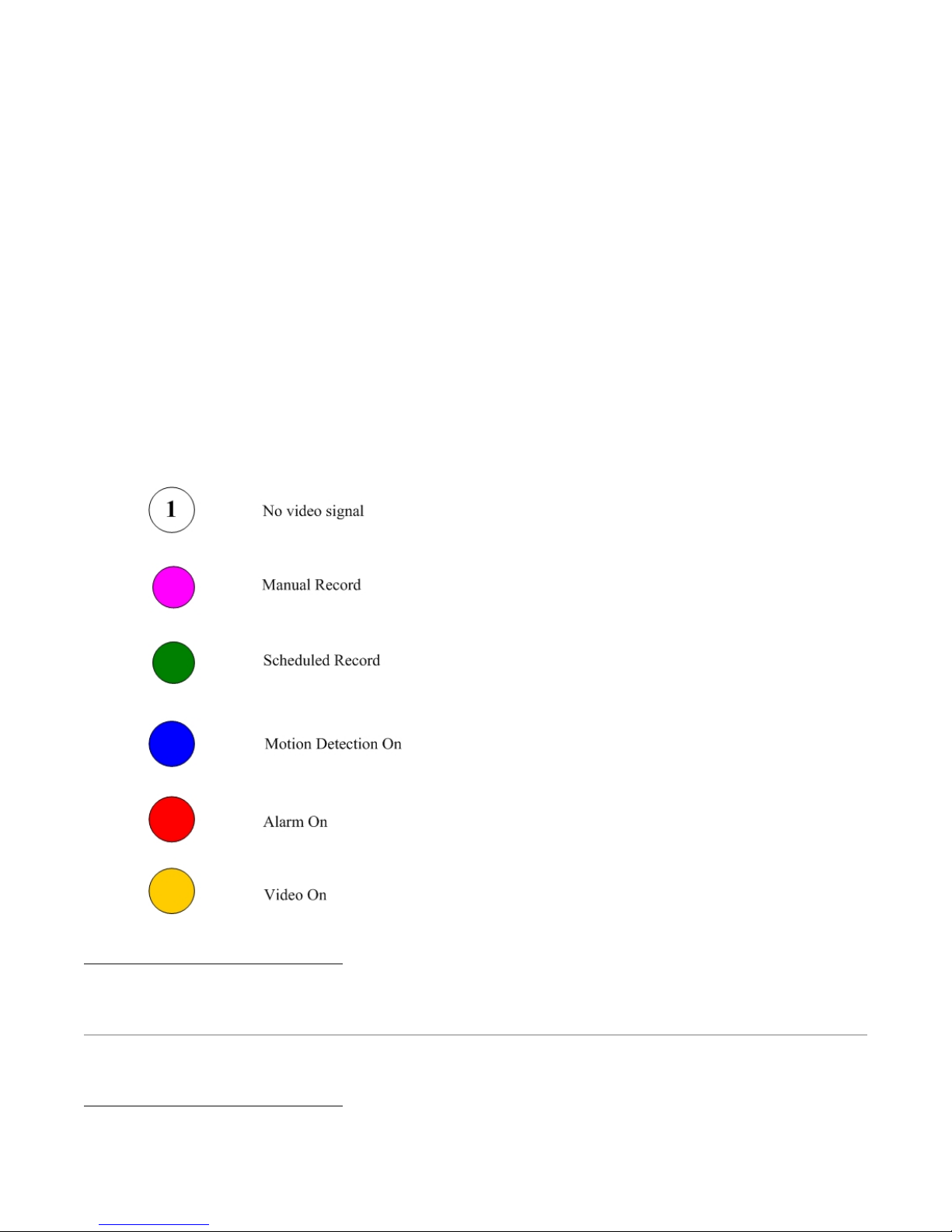
R
Appendix F
Camera Status Lights on Screen
The circles shown at the bottom of the monitor screen indicate the following states:
Page 78 of 79User Manual NV
12/7/2005https://serenity-support.gviss.com/html/doc/UserManNVR.htm
Page 79
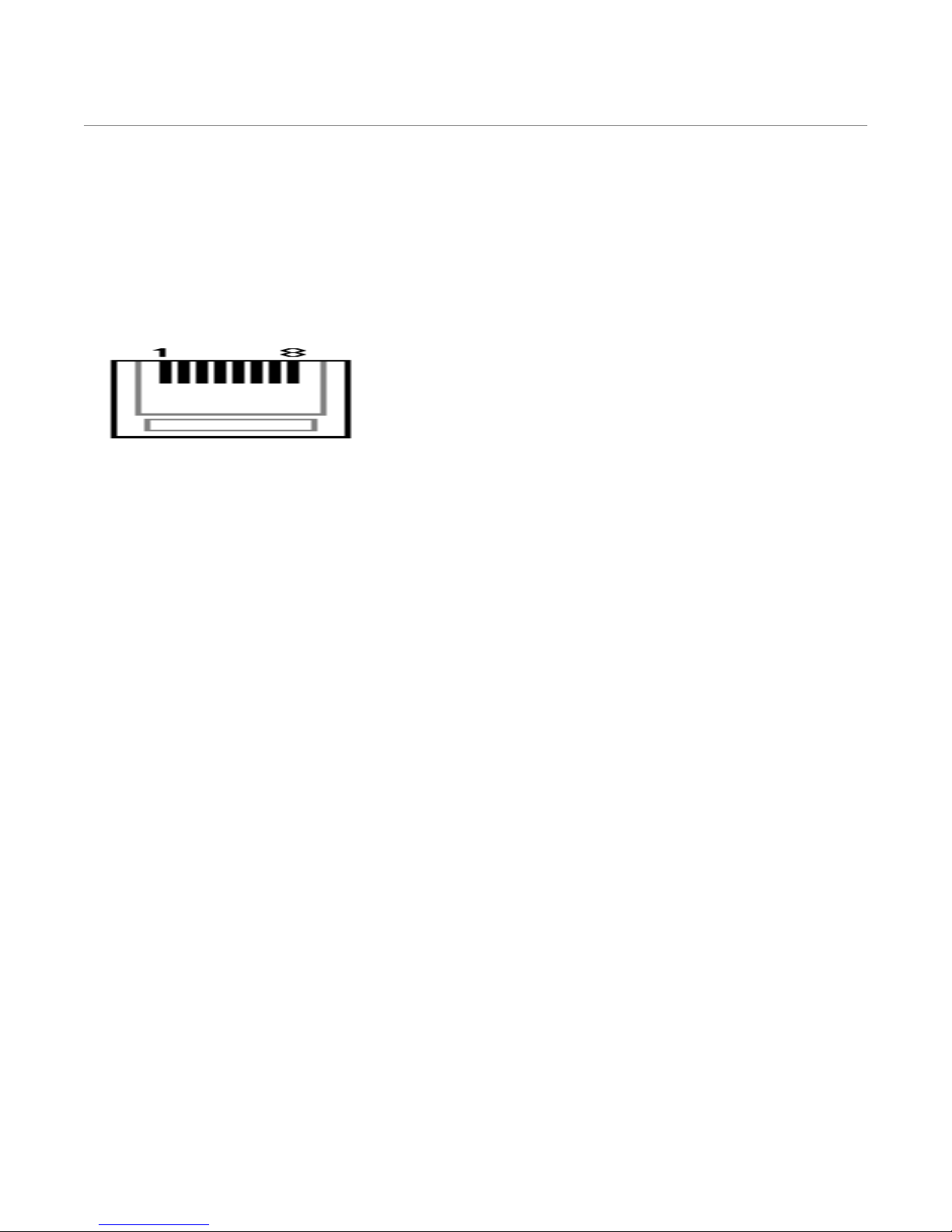
Page 79 of 79User Manual NV
R
76
76
12/7/2005https://serenity-support.gviss.com/html/doc/UserManNVR.htm
 Loading...