

SEREN R301 Operator's Manual

SEREN
INDUSTRIAL POWER SYSTEMS INC.
R301
RADIO FREQUENCY
POWER SUPPLY
OPERATOR’S MANUAL
Revision: 0.05
Standard Configuration
PRELIMINARY
SERIAL INTERFACE NOT IMPLEMENTED
Document Number 6100130000
SEREN Industrial Power Systems, Inc.
1717 Gallagher Drive
Vineland, New Jersey, 08360
U.S.A
Telephone: 856-205-1131
Fax: 856-205-1141
E-mail: info@serenips.com
Copyright ã 2003, 2004 Seren IPS Inc.

R301 RF POWER SUPPLY OPERATOR’S MANUAL
Introduction
Thank you for acquiring your new SEREN IPS product. The R301 Radio Frequency Power
Supply has been designed to provide the best value, ease of operation, and reliability for plasma
processing systems. This manual covers specifications, installation, and operation of the R301
RF Power Supply.
Information
To get answers for any questions you might have regarding your plasma or processing system,
please contact your system vendor first. Your system vendor knows the intimate details of how
your equipment interfaces and operates with the R301 RF Power Supply and can efficiently
resolve system related problems.
For questions directly related to the R301 RF Power Supply, you may call us, Monday through
Friday, 8:00am to 5:00pm, United States Eastern Time, at:
1-856-205-1131
Service
For RF Power Supplies purchased with a processing system, or covered under a service contract
from your system vendor, please contact the system vendor to arrange for service.
For after-market or end user customers, a SEREN IPS customer service representative will
arrange for service. Call us, Monday through Friday, 8:00am to 5:00pm, United States Eastern
Time, at: 1-856-205-1131
Please note: Equipment returned to us without prior authorization or without a Return Materials
Authorization (RMA) number visible on the outside of the package will be refused.
How to Contact Us
Our address, telephone, and fax numbers are listed below.
SEREN Industrial Power Systems, Inc.
1717 Gallagher Drive
Vineland, New Jersey, 08360 U.S.A.
Telephone: 856-205-1131
Fax: 856-205-1141
Proprietary Information Notice
This document contains information proprietary to SEREN IPS Inc. This document shall not be
reproduced or its contents disclosed without the written permission of SEREN IPS Inc. This
notice shall appear in all copies.
Seren IPS Inc.
6100130000 Rev. 0.05
Page 1

R301 RF POWER SUPPLY OPERATOR’S MANUAL
TABLE OF CONTENTS
Safety Notes ………………………………………………………………………... 3
R301 RF Power Supply Features ……………………………………………..……. 5
Physical Dimensions ………………………………………………………..……… 6
Installation ……………………………………………………………………….… 8
Front Panel Controls and Display ………………………………………………..… 10
Operation ………………………………………………………………………...…. 12
Basic Front Panel Operation ..………………………………………….…….….. 12
Analog Interface Operation …………………………………………………….... 16
Serial Interface Operation ……………………………………………………….. 18
Configuring Programmable Parameters …………………………………………. 27
Programmable Parameter Reference …………………………………………….. 27
Programmable Parameter Details ……………………………………………….. 29
Rear Panel Controls and Connections ……………………………………………… 34
CEX IN Connector ……………………………………………………………..... 35
CEX OUT Connector …………………………………………………………..... 35
Analog Interface Connector Pin List and Functional Description ………………. 36
Typical Interface Circuits ……………………………………………………… 41
Serial Interface Connector Pin List and Functional Description ………………... 44
Typical Interface Connections ……………………………………………………... 45
Probe Inverter Option Connections ……………………………………………… 46
Typical System Configuration ……………………………………………………... 48
Maintenance ………………………………………………………………………... 49
Problem Solving ……………………………………………………………………. 50
Technical Data ……………………………………………………………………… 52
SEREN 1 Year Limited Warranty ………………………………………………….. 54
Obtaining Service for the R301 RF Power Supply ………………………………… 54
Glossary of Terms ………………………………………………………………….. 55
Revision History …………………………………………………………………… 57
Seren IPS Inc.
6100130000 Rev. 0.05
Page 2
R301 RF POWER SUPPLY OPERATOR’S MANUAL
Safety Notes
The R301 RF Power Supply has been designed and tested to meet strict safety requirements.
These include independent lab examination and approval, and compliance to established
standards. Please read the following instructions carefully before operating the R301 RF Power
Supply and refer to them as needed to ensure the continued safe operation of the R301 RF Power
Supply.
Follow all warnings and instructions marked on or supplied with the product.
Symbology:
= CAUTION
!
PROTECTIVE
=
GROUND
HIGH
=
VOLTAGE
RADIO FREQUENCY
=
ENERGY HAZARD
EQUIPOTENTIAL BONDING
=
POINT
Unplug or disconnect this equipment from the power source before cleaning or re-configuring
the AC mains voltage.
Do not use this equipment near water, wet locations, or outdoors.
Do not place this equipment on an unstable cart, stand, or table. The R301 RF Power Supply
may fall, causing personal injury or damage to the R301 RF Power Supply .
This product is equipped with a 3-wire power cord and grounding type plug. This is a safety
feature. To avoid electric shock, this unit must be connected to the power source in compliance
with the National Electrical Code ANSI C1 and/or any other codes applicable to the user.
Improper installation may result in a shock or fire hazard.
It is the responsibility of the installer to provide a proper protective ground from the R301 RF
Power Supply to earth ground, in accordance with local and national electrical codes, and any
other codes applicable to the user.
R301 RF Power Supply should be operated from the type of power source indicated by the
ratings plate. If you are not sure of the type of power available, consult an electrician or your
local power company.
The power supply cord and plug is the disconnect device for this equipment. If the plug is
removed from the cord and the power cord is hard wired to the power source, it is the
responsibility of the installer to provide a disconnect device.
Do not allow anything to rest on the power cord or interconnecting cables. Do not locate the
R301 RF Power Supply where persons will step on the power or interconnecting cables.
Slots and Openings in the equipment’s chassis are provided for ventilation. To ensure reliable
operation of the R301 RF Power Supply, these openings must not be blocked, covered, or
restricted. Restricting the air inlets or exhaust will cause the unit to overheat. Sustained over
temperature conditions may degrade or damage the unit.
Seren IPS Inc.
6100130000 Rev. 0.05
Page 3

R301 RF POWER SUPPLY OPERATOR’S MANUAL
Never push objects of any kind into the slots and openings of the R301 RF Power Supply’s
enclosure. They may touch dangerous voltage points or short out parts, which could result in a
fire or electric shock.
Never spill liquid of any kind on or into the R301 RF Power Supply.
Never remove covers or guards that require a tool for removal. There are no operator
serviceable areas within these covers. Refer servicing to qualified service personnel.
CAUTION!
!
ELECTRICAL SHOCK HAZARD PRESENT
INSIDE UNIT, AT THE RF OUTPUT
CONNECTOR, AND AT THE MAINS INPUT
CONNECTOR.
DO NOT REMOVE COVERS.
REFER SERVICING TO QUALIFIED SERVICE
PERSONNEL.
Seren IPS Inc.
6100130000 Rev. 0.05
Page 4

R301 RF POWER SUPPLY OPERATOR’S MANUAL
R301 Radio Frequency Power Supply Features
The R301 RF Power Supply is intended for use with radio frequency plasma processing systems
and radio frequency processing applications.
The R301 RF Power Supply provides a 13.56MHz, level-controlled radio frequency power
output up to 300 Watts. The R301 RF Power Supply provides operator-accessible controls, a
visual display of power supply status, and a control interface to the user’s processing system.
Other R301 features are listed below:
· ½ Rack, 3U High Package
· 98-125VAC or 198-250VAC AC Mains
· Crystal-controlled internal frequency source
· Bright, easy to read 4 Line Vacuum Fluorescent Display, capable of displaying Forward
and Reflected RF Power, Control Mode, Power Supply status, and RF or DC Probe
Voltage.
· Front panel controls for RF On/Off, mode selection, and programming
· Front Panel, Analog, and Serial control interfaces
· Forward Power and Load (Net) Power Leveling
· Scaleable Forward and Reflected power metering (requires interface connection to user’s
system)
· Scalable RF and DC Probe Voltage display
· Remote control operation via analog system interface connector
· Common Exciter input and output
· Voltage Probe Inverter Option Available
· Air cooled
Seren IPS Inc.
6100130000 Rev. 0.05
Page 5

R301 RF POWER SUPPLY OPERATOR’S MANUAL
Physical Dimensions
5.25 [133.35]
3.75 [95.25]
1.50 [38.10]
0.00 [0.00]
]
0
0
.
0
[
0
0
.
0
SEREN
Industrial Po wer Systems
R301
RADIO FREQUENCY POWER SUPPLY
]
7
5
.
7
[
0
3
.
0
POWER
OI
RF
ON / OFF
]
]
0
6
3
7
.
.
1
3
4
3
2
2
[
[
0
0
5
2
.
.
9
9
5.25 [133.35]
0.00 [0.00]
Front View, R301 RF Power Supply
Dimensions in Inch [mm]
]
]
5
0
4
0
.
.
0
4
[
[
0
8
0
1
.
.
0
0
Side View, R301 RF Power Supply
]
]
9
8
0
0
.
.
6
1
6
8
4
4
[
[
5
4
3
9
.
.
8
8
1
1
Dimensions in Inch [mm]
Seren IPS Inc.
6100130000 Rev. 0.05
Page 6
5.25 [133.35]
4.32 [109.60]
R301 RF POWER SUPPLY OPERATOR’S MANUAL
RF OUT
DCP
!
2.62 [66.47]
1.86 [47.12]
0.89 [22.50]
0.00 [0.00]
POWER
1
]
0
0
.
0
[
0
0
.
0
]
5
1
.
2
2
[
7
8
.
0
S
E
R
A
I
N
A
A
L
L
O
G
CEX
IN
CEX
OUT
]
1
8
.
5
6
[
9
5
.
2
Rear View, R301 RF Power Supply
Dimensions in Inch [mm]
]
5
9
.
4
3
1
[
1
3
.
5
]
0
2
.
3
0
2
[
0
0
.
8
Seren IPS Inc.
6100130000 Rev. 0.05
Page 7
R301 RF POWER SUPPLY OPERATOR’S MANUAL
Installation:
Recommended mounting:
The R301 RF Power Supply is designed for placement on a tabletop or on a shelf within an
equipment rack, with another ½ Rack 3U piece of equipment, in a clean environment. The
table or equipment rack must be capable of supporting the full weight of the unit.
The R301 RF Power Supply is supplied with ½-Rack Mounting Ears. The mounting ears
are designed for securing the R301 to the equipment rack rail. The ½-rack mounting ears
are not
designed to support the weight of the R301 RF Power Supply. The user must
provide a shelf within the equipment rack to support the weight of R301. The user is
responsible for providing mounting hardware.
Note: the weight of the R301 RF Power Supply
is 43 pounds (19.5 kg)
Optional Mounting:
One (1) R301 RF Power Supply may be mounted in a 19” equipment rack with the use of
the optional single rack mount kit. The user must provide a shelf within the equipment
rack to support the weight of R301 unit.
Two (2) R301 RF Power Supplies in a 19” equipment rack with the use of the optional dual
rack mount kit. The user must provide a shelf within the equipment rack to support the
weight of two (2) R301 units.
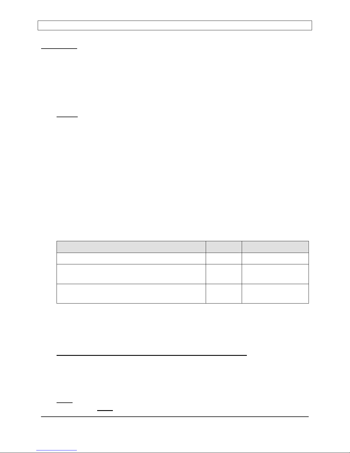
Supplied Accessories:
Description Quantity Seren Part Number
½-Rack Mount Ear, 3U 2 4304870000
Power Cord (for 98-125V models) 14AWG,
* 4500910000
IEC320-13 Receptacle to NEMA 5-15 Plug
Power Cord (for 198-250V models) 14AWG,
* 4500910001
IEC320-13 Receptacle to NEMA L6-15 Plug
* Only 1 power cord is supplied with the R301 RF Power Supply. The power cord type
depends on the AC Mains voltage specified at time of order.
Connection to AC Mains:
BEFORE connecting the R301 RF Power Supply the AC mains, verify the AC Mains
voltage marked on the ratings plate, located on the top panel of the R301 RF Power Supply,
is compatible with your AC Mains voltage. If the AC Mains voltage on the ratings plate is
not compatible with your AC Mains voltage, contact a Seren IPS Inc. service depot and
arrange to have the mains voltage re-configured.
Note:
Incorrect AC Mains voltage may damage the R301 RF Power Supply. The AC
Mains voltage is not
field configurable.
Seren IPS Inc.
6100130000 Rev. 0.05
Page 8

R301 RF POWER SUPPLY OPERATOR’S MANUAL
RF Output Connection:
Connect the R301 RF Power Supply’s RF output to a suitable load via a coaxial cable.
Depending on the load configuration and application, several coaxial cable types may be
used. Consult with the Seren IPS Inc. sales department, customer service department, or a
Seren IPS Inc. representative to select the cable appropriate to your installation.
Coaxial cable types RG-213/U, RG-225/U or RG-393/U are typically used with R301 RF
Power Supply installations.
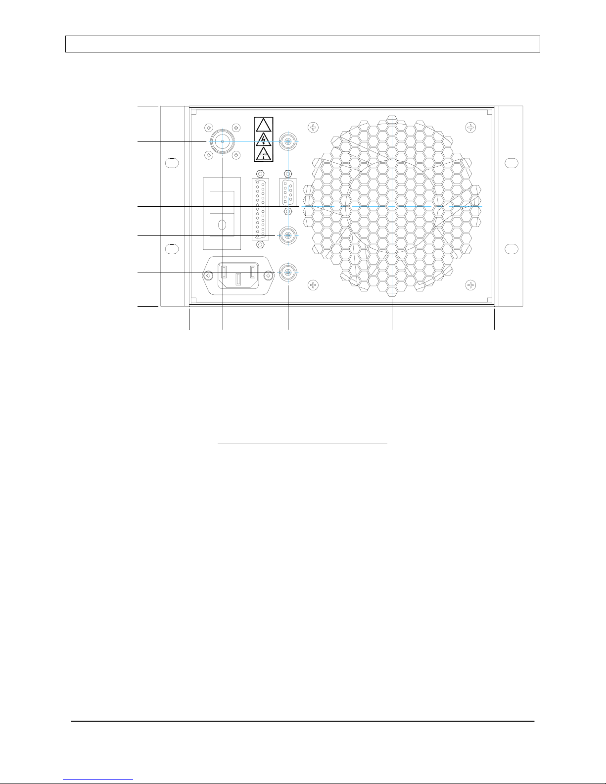
System Interfacing:
The R301 RF Power Supply can be used “stand-alone” or can be interfaced with a
processing system. There are five (5) connectors on the rear panel dedicated to system
interfacing. Refer to the Rear Panel Controls and Connections for detailed pin lists and
signal descriptions. There are many possible interface schemes – a full discussion of
interface schemes is beyond the scope of this document. Contact the Seren IPS Inc.
customer service department if you require assistance with interface connections. A brief
summary of the connectors is listed below.
“Analog Control” Connector
Provides status and control signals for an external system controller to operate the R301
RF Power Supply. The EXTERNAL INTERLOCK circuit must
R301 will not turn on. Refer to the Rear Panel Controls and Connections
be completed or the
section for
details.
“Serial Interface” Connector
Serial communications port for computer control via RS-232 protocol.
“CEX IN” Connector
Radio Frequency signal input. The R301 uses the signal present at this connector as the
frequency source when the R301 is configured for “slave” operation in a multiple RF
power supply system.
“CEX OUT” Connector
Radio Frequency signal output. The signal present at this connector is the same
frequency the R301 is using to produce its RF output. This signal can be used as a
frequency signal source for other RF Power supplies in a multiple RF power supply
system.
“DCP” Connector
(optional)
Voltage Probe Inverter input. When installed, a 0 to –10VDC signal applied to this
connector produces a 0 to +10VDC output on pin 25 of the Analog Interface connector.
This optional circuit inverts the output of a passive DC Voltage Probe, such as used in the
Seren IPS Inc. MM-Series and PM-Series matching networks, when using external
feedback for power regulation (voltage control).
Seren IPS Inc.
6100130000 Rev. 0.05
Page 9
R301 RF POWER SUPPLY OPERATOR’S MANUAL
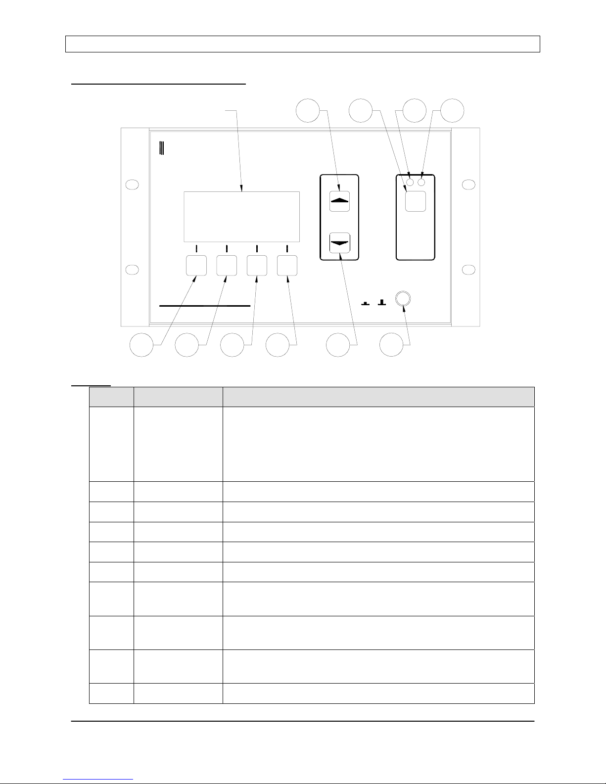
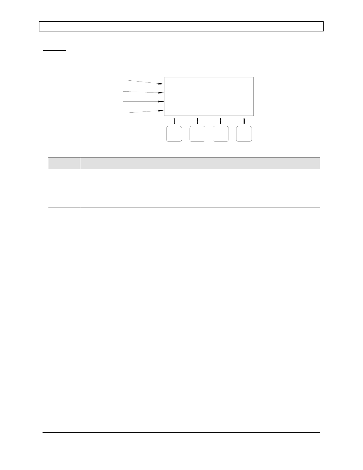
Front Panel Controls and Display:
DISPLAY
SEREN
Industrial Power Systems
PANEL
R301
RADIO FREQUENCY POWER SUPPLY
PWR
DOWNPGM
21
Buttons
Item Name Description
5
0W0W REF:SET:
MST
ENT
UP
POWER
I O
3
4
6
10
897
RF
ON / OFF
1 Program/Run Toggles the R301 RF Power Supply between the RUN mode
and PROGRAM mode. In Program mode, display line 3
changes to show Programmable Menu Entry Options. The
button legend changes from “PGM” to “RUN” when in the
Program mode.
2 Down Moves down the programming menu
3 Up Moves up the programming menu
4 Enter Programs (saves) changes made to a parameter
5 Value Up Changes Parameter Value - Increment
6 Value Down Changes Parameter Value - Decrement
7 RF ON/OFF Enables/Disables the RF output in “local” mode, disables the
RF output in any operational mode.
8 RF ON
Glows RED when the RF Output is enabled (on).
Indicator Lamp
9 RF OFF
Glows BLUE when the RF output is disabled (off)
Indicator Lamp
10 Power AC Mains power enable/disable
Seren IPS Inc.
6100130000 Rev. 0.05
Page 10
R301 RF POWER SUPPLY OPERATOR’S MANUAL
Display
The front panel display shows the operational status of the R301 RF Power Supply and
provides legends for the keypad.
Line Description
1 Power Display Line
Displays power setpoint and reflected power when the RF Output is disabled.
Displays forward power (or load power) and reflected power when the RF output
is enabled
2 Status Display Line
Displays the current control source, power control mode, exciter mode and
operational alarms. Operational alarms are flashed on the extreme right side of
the line (see the problem solving section for alarm details).
[CONTOL SOURCE] [POWER CONTROL MODE] [EXCITER MODE] [ALARM]
LINE 1
LINE 2
LINE 3
LINE 4
SET: 0W REF:
PANEL
PWR
MST
PANEL CONTROL
PGM
DOWN
UP
ENT
Control Source:
Panel = Front Panel Control
Analog = Analog Interface
Serial = Serial Interface
Power Control Mode:
PWR = Forward Power Leveling (internal power sensor)
PLS = Pulsing Enabled (internal power sensor)
VLT = Voltage Control (external feedback)
Exciter Mode:
MST = Master (internal frequency source)
EXT = External (external frequency source)
0W
3 User Configurable Display Line
In RUN mode:
Displays DC Voltage Probe or RF Voltage Probe output
(User enabled or disabled)
In PROGRAM mode:
Displays a programmable parameter and its current setting.
4 Keypad Menu – button legends change depending on mode
Seren IPS Inc.
6100130000 Rev. 0.05
Page 11

R301 RF POWER SUPPLY OPERATOR’S MANUAL
Operation
Front panel operation of the R301 RF Power Supply is simple. This section describes the use
and operation of the front panel controls in a “how to…” manner. Refer to the front panel
illustration on the previous page for item references.
Connect the R301’s RF output to a 50-Ohm, 500 Watt resistive load, Impedance
!
Basic Front Panel Operation
Mains Power On/Off:
Press the POWER button (item 10) to enable mains power – the front panel display will
illuminate and momentarily display the firmware revision and copyright. Press the POWER
button again to disable mains power.
Control Source:
The control source is the control interface for the R301 RF Power Supply. The R301 RF
Power Supply has three (3) user-selectable control sources.
· The “PANEL” control source is for front panel operation of the R301.
· The “ANALOG” control source is for controlling the R301 from the user’s system, via
the rear panel ANALOG INTERFACE connector.
· The “SERIAL” control source is used for controlling the R301 from a computer, via an
RS-232, RS-422, or RS-485 interface.
To select a control source, follow the directions below:
PANEL control:
To change the control source to the front panel,
1. Press the PGM button (Item 1) once.
2. Press the DOWN button (item 2) or the UP button (item 3) until line 3 of the display
3. Press the VALUE UP button (item 5) or the VALUE DOWN button (item 6) until
4. Press the ENT button (item 5) to save the selection.
5. Press the RUN button (item 1) to return to exit the programming menu.
ANALOG control:
To change the control source to the Analog interface connector,
1. Press the PGM button (Item 1) once.
Matching network, processing system or other suitable load before enabling AC
mains Power.
shows the current control source (PANEL CONTROL, ANALOG CONTROL, or
SERIAL CONTROL).
PANEL CONTROL is displayed on line 3.
Seren IPS Inc.
6100130000 Rev. 0.05
Page 12

R301 RF POWER SUPPLY OPERATOR’S MANUAL
2. Press the DOWN button (item 2) or the UP button (item 3) until line 3 of the display
shows the current control source (PANEL CONTROL, ANALOG CONTROL, or
SERIAL CONTROL).
3. Press the VALUE UP button (item 5) or the VALUE DOWN button (item 6) until
ANALOG CONTROL is displayed on line 3.
4. Press the ENT button (item 5) to save the selection.
5. Press the RUN button (item 1) to return to exit the programming menu.
SERIAL control:
To change the control source to the Serial interface connector,
1. Press the PGM button (Item 1) once.
2. Press the DOWN button (item 2) or the UP button (item 3) until line 3 of the display
shows the current control source (PANEL CONTROL, ANALOG CONTROL, or
SERIAL CONTROL).
3. Press the VALUE UP button (item 5) or the VALUE DOWN button (item 6) until
SERIAL CONTROL is displayed on line 3.
4. Press the ENT button (item 5) to save the selection.
5. Press the RUN button (item 1) to return to exit the programming menu.
Note: Pressing the RUN button (item 1) automatically saves the current setting and
exits the
programming menu.
Note: The control source and control mode selection is saved when the R301 RF Power
Supply is powered down – it will power-up in the same mode.
Leveling Mode:
The leveling mode is the method the R301 uses to regulate its output power. There are three
(3) leveling mode selections.
· The “PWR” (power) leveling mode uses the R301’s internal power sensor to regulate the
RF output power. There are two types of power leveling available on the R301 RF
Power Supply:
1. Forward (FWD) Power leveling: The forward output power is measured by the
R301’s internal power sensor and compared against the requested output power
(power setpoint). The R301’s power amplifier increases or decreases its output to
maintain the requested power setpoint. Reflected power is displayed and
monitored for internal protection.
2. Load Power Leveling: The forward and reflected power is measured by the
R301’s internal power sensor. The reflected power signal is subtracted from the
forward power signal and compared against the requested net power (power
setpoint) to be delivered to the load. The R301’s power amplifier output increases
or decreases its output to maintain the net power delivered to the load. Reflected
power is displayed and monitored for internal protection.
Seren IPS Inc.
6100130000 Rev. 0.05
Page 13

R301 RF POWER SUPPLY OPERATOR’S MANUAL
· The “VOLTAGE” (VLT) leveling mode uses an external feedback voltage (derived from
a Voltage Probe in the processing system’s matching network or processing chamber) to
regulate the RF output power.
To select a leveling mode, follow the directions below:
Forward (FWD) Power Leveling mode:
1. Press the “PGM” button (item 1).
2. Press the “DOWN” button (item 2) 4 times, or until line three of the display is
“POWER CONTROL” or “VOLTAGE CONTROL”
3. Press the “VALUE UP” button (item 5) or “VALUE DOWN” (item 6) until line 3 of
the display indicates the desired power leveling mode, “POWER CONTROL”.
The text on the left side of display line 2 should change to “PANEL PWR”
4. Press the “ENT” button (item 4) to save the mode selection.
5. Press the “DOWN” button (item 2) 2 times, or until line three reads “FWD POWER
LEVELING” or “LOAD POWER LEVELING”
6. Press the “VALUE UP” button (item 5) or “VALUE DOWN” (item 6) until line 3 of
the display indicates the desired power leveling mode, “FWD POWER
LEVELING”.
7. Press the “ENT” button (item 4) to save the mode selection.
5. Press the “RUN” button (item 1) to exit the programming menu.
Voltage (VLT) Leveling mode:
1. Press the “PGM” button (item 1).
2. Press the “DOWN” button (item 2) 4 times, or until line 3 of the display is “POWER
CONTROL” or “VOLTAGE CONTROL”
3. Press the “VALUE UP” button (item 5) or “VALUE DOWN” (item 6) until line 3 of
the display indicates the desired power leveling mode, “VOLTAGE CONTROL”.
The text on the left side of display line 2 should change to “PANEL VLT”
4. Press the “ENT” button (item 4) to save the mode selection.
5. Press the “RUN” button (item 1) to exit the programming menu.
Load (VLT) Power Leveling mode:
1. Press the “PGM” button (item 1).
2. Press the “DOWN” button (item 2) 4 times, or until line three of the display is
“POWER CONTROL” or “VOLTAGE CONTROL”
3. Press the “VALUE UP” button (item 5) or “VALUE DOWN” (item 6) until line 3 of
the display indicates the desired power leveling mode, “POWER CONTROL”.
The text on the left side of display line 2 should change to “PANEL PWR”
4. Press the “ENT” button (item 4) to save the mode selection.
5. Press the “DOWN” button (item 2) 2 times, or until line three reads “FWD POWER
LEVELING” or “LOAD POWER LEVELING”
Seren IPS Inc.
6100130000 Rev. 0.05
Page 14

R301 RF POWER SUPPLY OPERATOR’S MANUAL
6. Press the “VALUE UP” button (item 5) or “VALUE DOWN” (item 6) until line 3 of
the display indicates the desired power leveling mode, “LOAD POWER
LEVELING”.
7. Press the “ENT” button (item 4) to save the mode selection.
8. Press the “RUN” button (item 1) to exit the programming menu.
Set Output Power Level
1. Ensure the R301 RF Power Supply is in the “RUN” mode – the legend above the
Program/Run button (item 1) is “PGM”.
2. Use the Value Up button (item 5) or Value Down button (item 6) to adjust the power
setpoint (SET: XXXW on the front panel display) to the desired power level.
Enable RF Output
1. Ensure the R301’s RF output is connected to an appropriate load and the external
interlock (Analog Interface Connector, pin 2) is in the proper state.
2. Press the front panel RF ON/OFF button (item 7). The blue RF OFF lamp will
extinguish (item 9) and the red RF ON lamp will illuminate.
3. The left side of line one on the display will change from “SET XXXW” to “FWD
XXXW”
Disable RF Output
1. Press the front panel RF ON/OFF button (item 7). The red RF ON lamp should
extinguish (item 9) and the blue RF OFF lamp will illuminate.
2. The left side of line one on the display will change from “FWD XXXW” to “SET
XXXW”
Seren IPS Inc.
6100130000 Rev. 0.05
Page 15

R301 RF POWER SUPPLY OPERATOR’S MANUAL
Basic Analog Interface Operation
Refer to the Rear Panel Controls and Connections and the Typical Interface Connections
sections for detailed analog interface operation and connection information.
Connect the R301’s RF output to a 50-Ohm, 500 Watt resistive load, Impedance
!
1. Make control connections to the rear panel ANALOG INTERFACE connector.
2. Press the front panel POWER button (item 10) to enable mains power – the front panel
display will illuminate and momentarily display the firmware revision and copyright.
3. Select ANALOG control mode.
Note: The ANALOG control mode only needs to be selected once. The R301 RF power
supply will retain the selected control mode during a power-off/power-on cycle.
a. Press the PGM button (Item 1) once.
b. Press the DOWN button (item 2) or the UP button (item 3) until line 3 of the display
c. Press the VALUE UP button (item 5) or the VALUE DOWN button (item 6) until
d. Press the ENT button (item 5) to save the selection.
e. Press the RUN button (item 1) to exit the programming menu.
4. Select the desired leveling mode “Power” or “Voltage”.
Apply an open circuit or TTL “high” signal to Analog Interface Connector pin 4 to select
the power supply’s internal power sensor for power regulation. A contact closure
between Analog Interface Connector pin 4 and pin 16 or a TTL “low” signal applied to
pin 4 selects forward power regulation based on an external feedback signal
(FEEDBACK signal – Analog Interface Connector pins 12 and 24).
5. Apply the desired setpoint voltage to pins 21 and 23
6. Enable the Analog Interface Connector’s external interlock (INTERLOCK) circuit.
Connect Analog Interface connector pin 2 to pin 15 or apply a TTL logic “low” signal to
pin 2.
7. Enable the Analog Interface Connector’s RF On (RFON*) circuit. Connect Analog
Interface Connector pin 3 to pin 16 or apply a TTL logic “low” signal to pin 2.
Matching network, processing system or other suitable load before enabling AC
mains Power.
shows the current control source (PANEL CONTROL, ANALOG CONTROL, or
SERIAL CONTROL).
ANALOG CONTROL is displayed on line 3.
Seren IPS Inc.
6100130000 Rev. 0.05
Page 16

R301 RF POWER SUPPLY OPERATOR’S MANUAL
Note: the RFON* signal is edge triggered. A transition from a TTL
“high” to TTL “low” logic state must occur to enable the RF output. This
prevents accidental enabling of the RF output when the RF power supply
!
8. Adjust the setpoint voltage as required.
9. Disable the RF Output. Open the connection between Analog Interface Connector pin 3
to pin 16 or apply a TTL logic “High” signal to pin 2.
is powered-up in the ANALOG control mode or when the external
interlock (INTERLOCK) is re-established after an external system
interlock event.
Seren IPS Inc.
6100130000 Rev. 0.05
Page 17
 Loading...