

sereco NE Series Installation And Operation Manual
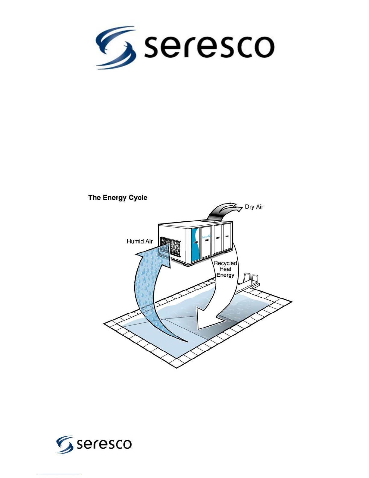
Seresco: (pronounced Sir-ES-co) meaning “to become dry”
Installation and Operation Manual
NE Series Dehumidifiers
For NE-208-232 Models:
PV, NV, PH and NH Configuration Natatorium Dehumidifiers
NC Series Outdoor Air-cooled Condensers
1
CAUTION
ONLY TRAINED, QUALIFIED PERSONNEL SHOULD INSTALL AND/OR SERVICE SERESCO
EQUIPMENT. SERIOUS INJURY AND PROPERTY DAMAGE CAN RESULT FROM
IMPROPER INSTALLATION/SERVICE OF THIS EQUIPMENT. HIGH VOLTAGE ELECTRICAL
COMPONENTS AND REFRIGERANT UNDER PRESSURE ARE PRESENT
1-888- SERESCO (737-3726)
Additional copies of this manual can be downloaded from:
www.seresco.net
Seresco Technologies Incorporated
1283 Algoma Road, Unit 1
Kanata, Ontario,
K1B 3W7
2

TABLE OF CONTENTS
1. Introduction ...................................................................………………...................…… 4
1.1 Packaged Mechanical Refrigeration Systems............................................….........…… 5
1.2 NE Series Dehumidifier features……..............................................….........…………… 6
2. Installation .................................................................................………….……………..
2.1 Uncrating and Inspecting..................................................................................….…… 7
2.2 Mounting and Service Clearance………………………….........................................…… 7
2.3. High Voltage Electrical Connections ...................................................................…….. 8
2.3.1 Wire and Fuse Sizing.............................................................................…… 8
2.3.2 Line Voltage Connections.................................................................….…… 8
2.4. Control Wiring......……………………...................................................................……… 8
2.5. Controller and Programming....................……........................................................…… 9
2.5.1 Normal Mode and Programming……………........................................…….. 10
2.5.3 Logs…………….....................................……………………………………….. 11
2.5.5 Sensors and locations………….....................................…………………….. 12
2.6. System Design Overview….................................................................…………....……. 13
2.6.1 System duct design and air pattern ………...................................….......….. 13
2.6.2 Evaporation rate and latent loads…………...................................….......….. 14
2.6.3 Required Access Space……………………...................................….......…… 14
2.6.4 Exhaust Air……….........…………………………….........................…......…… 15
2.6.5 Supply Air flow…………………………….…...................................…......…… 15
2.6.6 Cooling and Heating loads…………………....................................…......…… 15
2.6.7 Outdoor Air……………………………………...................................…......…... 15
2.7. Condensate Drain ….........................................................………............................…… 16
2.8. Pool Water Heating (PH AND PV Models Only)…..................................……………….. 16
2.8.1 Water Flow Schedule …………................................................................…... 16
2.8.1 Pool Water Piping Diagram ………...............................................…………… 17
2.9. Outdoor Air-cooled Condenser Installation......................…………...........................….. 18
2.9.1 Refrigerant Piping to Remote Condensers....……................................….. 18
2.9.2 Charging of Remote Condensers…......................………………………....….. 19
3. Pool Water Chemistry ….................……………………..…...............……….............… 20
4. Start-up Procedures …...........................…………….....................………….........…….. 21
4.1. Pre Start-up …........................................................…………….................................….. 21
4.2. Start-up Procedure ….............................................………........................................….. 21
4.3. System Operation Modes…..................................................................................……... 22
4.3.1 Power On………………………….….........................................................…... 22
4.3.2 Dehumidification Mode…......................……………...................................…. 22
4.3.3 Air Conditioning Mode …....................................................……………….….. 22
4.3.4 Pool Water Heating Mode (PH AND PV Models Only)…...........…………….. 22
4.3.5 Blower Operation….................................................………........................…. 22
4.3.6 Compressor Start Sequence…..........................................................….....…. 23
4.3.7 Air Heat Demand ….........................................................................….......…. 23
5. Service and Maintenance…................................................………………….……....... 23
5.1. Routine Maintenance….........................................................................………….......…. 23
5.2. Compressor Replacement…..................................................................................……. 23
6. Service References …………………………………………………………………………. 24
6.1. Nameplate …....................................................…………………................................…. 24
6.2. Mechanical System Trouble shooting….....................................................................…. 25
6.3. Microprocessor Trouble shooting…...........................................................................…. 27
6.4. Blower Adjustment Procedure…...................................................…………..............…. 28
6.5. Basic Unit Operation …...........................................................……………….……....…. 28
6.6. Factory Start-up Supervision…..…..........………….................................................…… 29
6.7. Warranty…………………….…..................................................…............................…… 30
6.8. Refrigeration Diagrams……………………….…....…..............….………………………… 32
6.9. Field Wiring Diagram…………………….…....…................….………………………… 33
6.10. Typical Electrical Panel Layout………..……………………..…......…..............…… 33
6.11. Warranty Registration and Start-up Report……………………..…......…..............…… 34
7
3
1. Natatorium: a facility that
contains an indoor pool,
whirlpool or spa ranging in size
from a small residential
installation to a large commercial
indoor waterpark.
Seresco’s Natatorium Dehumidifiers were
developed by a team of industry experts with a
lifetime of experience developed while working
with many thousands of indoor pools. A
natatorium has many critical design issues that
must be fully understood and properly addressed
to ensure years of comfortable and trouble free
operation of the facility.
This booklet contains valuable design guidelines
based on Seresco's extensive knowledge and
experience in solving humidity control problems
in many thousands of indoor pool installations.
Seresco Technologies Inc., manufacturer of the
NE Series of natatorium air quality control
systems is dedicated to providing state-of-the-art
features and design, quality engineering and the
most reliable products in the market.
The environment in a natatorium should be the
same as in any other room in a building:
comfortable and healthy for the occupants and
their activity, and provide good air quality. The
space conditions in a natatorium need to be
precisely maintained in order to maximize human
comfort and health as well as preserve building
integrity. Relative humidity, air temperature,
water temperature and air quality are all key
environmental aspects to control. High relative
humidity levels are not only a problem to bather
comfort and health, but can seriously damage the
building structure possibly leading to building
component failures. Revenues can also be
affected in commercial facilities. Several hotel
chains offer a full money-back guarantee should
the hotel guest have any complaint regarding
their stay.
A properly designed and maintained natatorium
delivers years of pleasure. The first step is to
become familiar with the design challenges and
to understand how to address them. A
Natatorium’s overall performance is inversely
proportional to the amount of compromises and
shortcuts taken in the design and construction of
the natatorium.
A Successful Facility. A natatorium is
one of the most notoriously difficult facilities to
design because there are so many critical
considerations that if overlooked develop into
problems with the building structure or complaints
from the occupants. The designer must take a
complete system approach, from basic
engineering issues to the more subtle details in
the air distribution. Experience and a complete
understanding of the design issues help the
designer satisfy:
Comfort and Health
Humidity Control
Indoor Air Quality
Condensation Control
Comfort and Health: Human comfort
levels are very sensitive to temperature and
relative humidity. It is essential that both are
controlled and stable. While temperature control
is generally well understood and mastered by
designers, it is important to recognize what
temperature levels natatorium patrons want. The
space temperatures in a natatorium are unique to
each project and assumptions must never be
made. Fluctuation of relative humidity levels can
be an even greater concern because it has a
direct effect on human comfort and health.
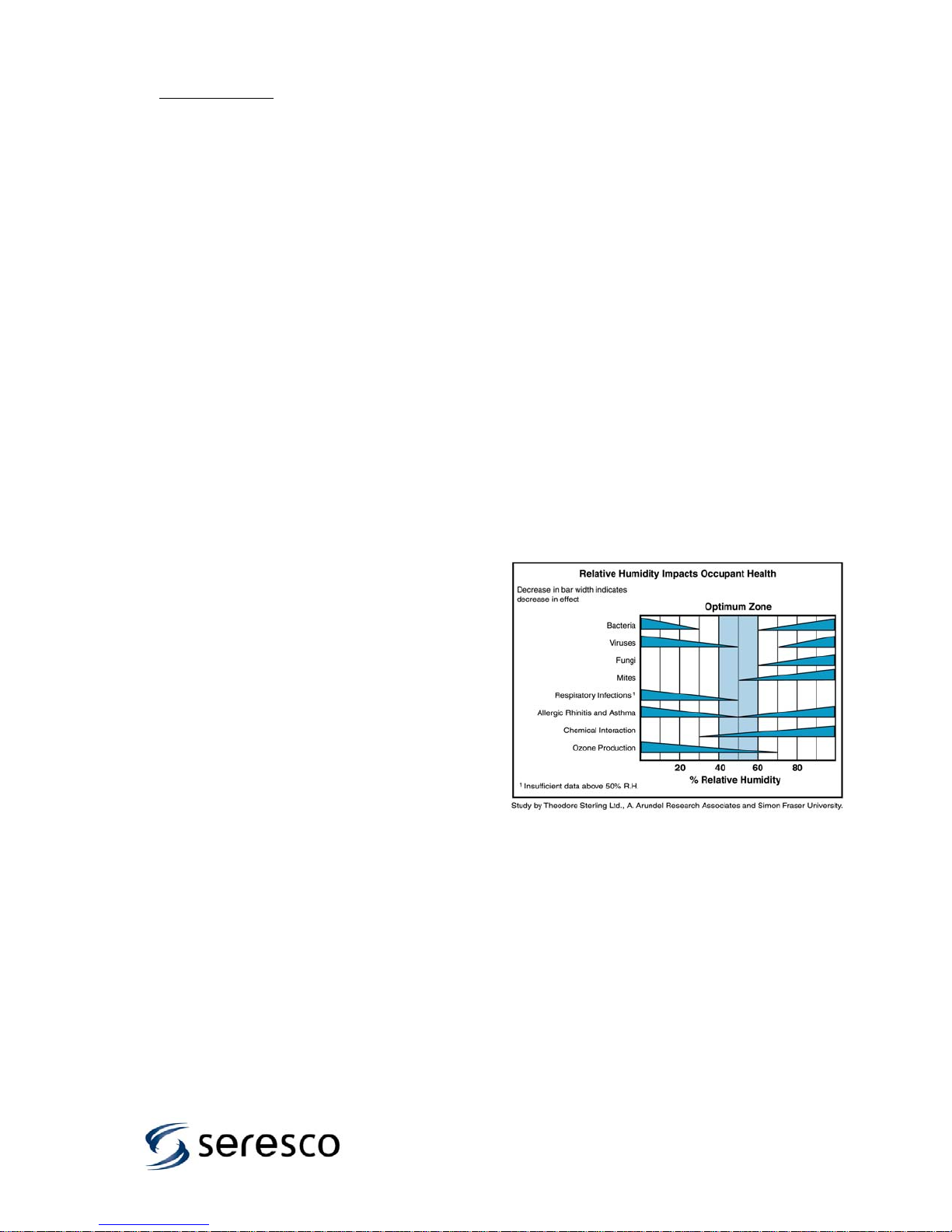
Figure 1 shows that relative humidity levels
outside the 40%- 60% range can result in
increased human susceptibility to disease from
bacteria, viruses, fungi and other contaminants
that reduce air quality and potentially lead to
respiratory problems.
Figure 1- Relative Humidity Effect on Health
Factors.
4

The type of facility being designed dictates the
space temperature. Table 1 helps target some
typical conditions. It is critical to understand who
will be using the facility in order to deliver the
conditions most likely to satisfy them.
Pool Type
Competition 78 to 85 76 to 82
Diving 80 to 85 84 to 88
Elderly Swimmers 84 to 85 85 to 90
Hotel 82 to 85 82 to 86
Physical Therapy 80 to 85 90 to 95
Recreational 82 to 85 80 to 85
Whirlpool/spa 80 to 85 102 to 104
Air
Temperature, °F
Water
Temperature, °F
Table 1 – Typical Natatorium Operating
Conditions
Indoor pools are normally maintained between 50
and 60% RH for two reasons:
Swimmers leaving the water feel chilly at lower
relative humidity levels due to evaporation off the
body and:
It is considerably more expensive (and
unnecessary) to maintain 40% RH instead of
50% RH.
General Notes:
Facilities with warmer water temperatures tend to
have warmer space temperatures.
Physical Therapy facilities will cater to therapist
comfort rather than the patient because they are
generally not in the space for more than an hour,
whereas the therapist is there all day. The
designer should consult local codes. Some
States require a full purge of the room air with
100% outdoor air for every hour of occupancy.
Elderly swimmers tend to prefer much warmer air
and water temperatures.
Humidity Control: High relative humidity
levels inside a building are well known for their
destructive effects on building structure and can
pose serious health concerns. Buildings with high
humidity levels are prone to condensation problems
that can destroy the building structure. They also
facilitate the growth of mold and mildew, which in
addition to being unsightly, can adversely impact
the air quality. Controlling humidity requires that a
total moisture load be accurately calculated. This
amount of moisture must be removed from the
space at the same rate it is generated to maintain
stable space conditions.
1.1 Packaged mechanical refrigeration
system. By far the most common and popular
method of removing moisture from the space, these
are packaged refrigeration units like those built by
Seresco. The units are designed and developed
specifically for dehumidifying indoor pools.
A major benefit of this approach is that both the
sensible and latent heat is combined with the heat
generated by the compressor’s power consumption
and can be directed to wherever heat may be
required in the natatorium. This process is unique in
the HVAC industry as is uses both the cooling and
heat rejection sides of the refrigeration cycle. The
system can be simultaneously dehumidifying
(cooling) the air and then reheating it (and/or the
pool water) to deliver dehumidified and reheated air
to the space, and warm water to the pool.
How it works. Figure 2 illustrates schematically
how warm humid air passes through the
dehumidifying coil and is cooled to below its dew
point. As a result moisture condenses out of the air.
Depending on the space temperature requirements
the hot gas from the compressor can be used to
reheat the air or reject its heat to an outdoor
condenser. Compressor hot gas can also be used
to heat the pool water
Figure 2 Mechanical Refrigeration System.
Typical Operating Conditions:
Air On Evaporator: 84°F, 50% RH
Air Off Evaporator: 50°F
Suction Pressure: 65 PSIG
High Pressure: 220 PSIG
Superheat: 12-15 °F
Pool Water Heat: in 84°F- out 92°F
.
5

1.2 NE Series Dehumidifier
Features. Figure 3 identifies where several
major components are located within the NE Series
unit.
Figure 3 – NE Series Dehumidifier Major
Components
1 - Air Filters. The standard filter is a 2” pleated
30% efficient filter. 4” 95% filters are available on
certain models. Access to the filters is through a
service access door.
2 - Evaporator. The coil is corrosion protected to
ensure a long lifespan and designed to ensure
premium dehumidification performance. It is also
recessed into the cabinet allowing these units to
perform even if the duct connection is less than
perfect.
3 - Drain Pan. The drain pan has compound slopes
to ensure zero water retention.
4 - Reheat Coil. This corrosion protected
condenser coil is capable of rejecting 100% of
compressor heat to the air steam.
5 - Blower. Plug fans are standard on all units. The
backward inclined airfoil blower wheel provides high
static pressure with low motor power. This feature
helps ensure the NE unit will perform to
specifications even if the duct connections to the
unit or if the overall duct installation are less than
ideal.
6 - Compressors: The NE Series is equipped with
robust high-efficiency scroll compressors.
7 - Direct driven blowers: No belts to adjust or
maintain! The motor is even out of the air stream.
The NE Series uses Inverter Spike Resistant direct
driven blower motors. This blower drive design
simplifies unit maintenance and delivers the air
more efficiently.
8 - Electrical Panel. All electrical components and
connections are inside this panel.
9 - Receiver. The receivers have two sight glasses.
This facilitates the system charging process
10 - Pool Water Heater. This coaxial heat
exchanger is provided with the PH and PV models.
The water circuit is corrosion resistant cupro-nickel
pipe.
11 - Command Center. The Keypad and Display
panel has a backlit graphic Liquid Crystal Display
(LCD) and 7 system status LEDs.
12 - Evaporator Bypass Damper. The motorized
bypass damper is controlled by the Command
Center and it is used to ensure the evaporator is
always operating at optimum pressures.
13 - Outside Air Opening. Manual air balancing
dampers are provided and two-inch air filters.
14 - Cabinet: Seresco has taken all possible
commercially feasible precautions to protect the NE
Series units against the corrosion. The sheet metal
is galvanized automotive grade G-90 with both
sides painted.
15 - Refrigerant Pressure transducers. These
allow the user or serviceman to access the vital
information of refrigerant pressures through the
operator panel of the microprocessor rather than
having to connect a set of refrigerant manifold
gauges. This is the most important operation and
diagnostic data for any refrigeration system.
6
2. Installation
2.1 Uncrating and Inspecting
Seresco inspects and fully tests each
dehumidifier in all operating modes before it
ships from the factory. The unit can suffer
damage in transit. Check the equipment
thoroughly for both visible and concealed
damage before you sign the receiving papers.
Document any damage in writing on the
carrier’s bill of lading to ensure that damage
claims are handled promptly. If the unit has
been damaged, obtain a claim form from the
carrier. Promptly fill out and return the form,
and notify Seresco of any damage.
Damage claims or missing parts must
be filed with the freight carrier.
2.2. Mounting and Service Clearance
The NE Series dehumidifier continuously
removes a significant amount of moisture from
the room air. Some models have a pool water
heating option. Condensate lines and pool
water circuits can leak.
Do not install the unit in a location
where a water leak will cause damage.
The mechanical room where the unit is
installed should have a floor drain.
If there is no floor drain, a secondary pan
with a drain or condensate pump should be
installed under the entire unit. (as is done
with a residential washing machine)
Do not store pool chemicals in the same
room as the dehumidifier.
Install the unit on an appropriate mounting
base or a platform. Install industry standard
components that prevent vibration and sound
transmission. Never install the dehumidifier on
a wooden platform that can resonate. Do not
install the unit near occupied rooms such as
bedrooms. Never suspend from the floor joists
of an occupied room above the mechanical
room. Never locate the unit above a swimming
pool or a spa water surface.
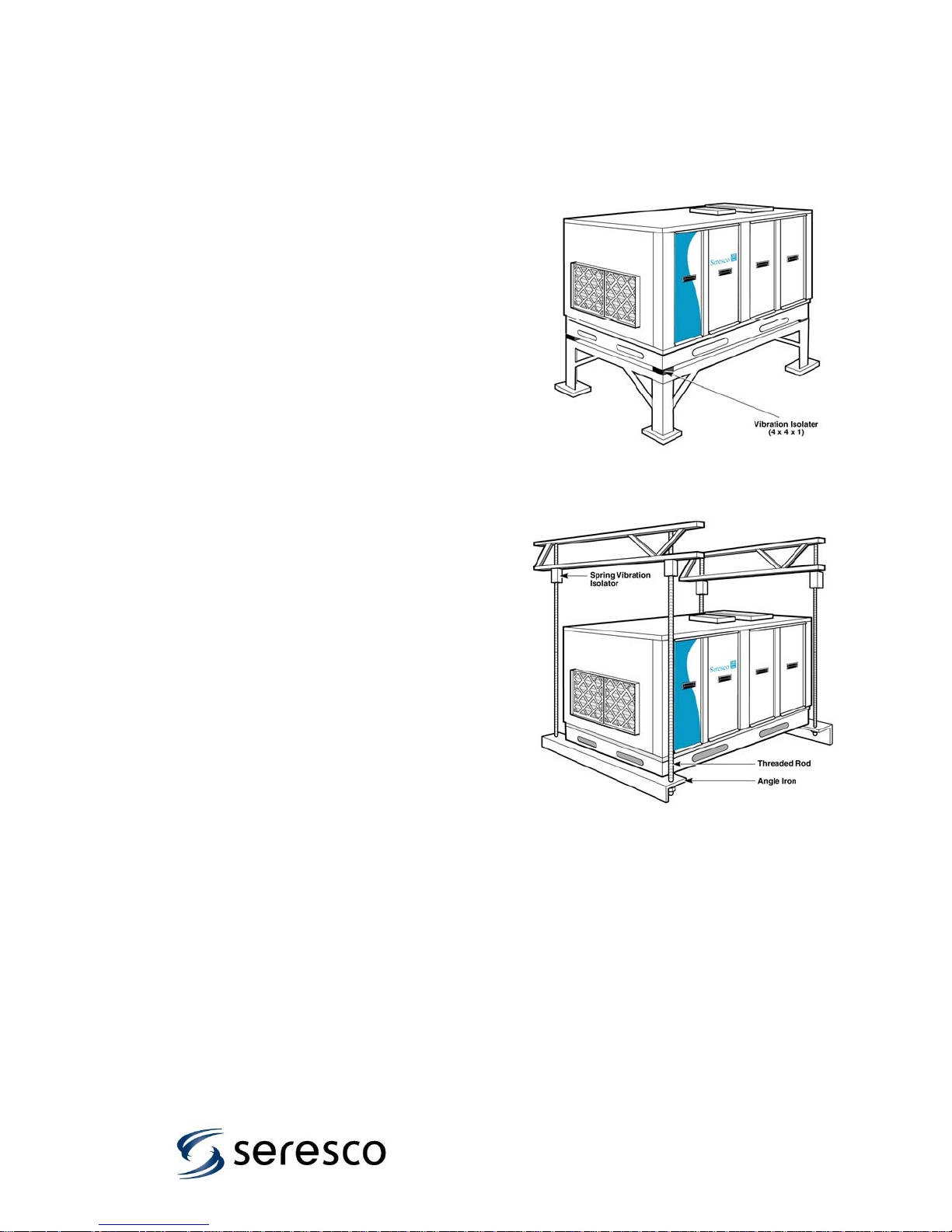
Figures 5 & 6 illustrate typical unit mounting
configurations.
Ensure the support structure will not
interfere with the operation of or access to
unit.
No Access = no service or maintenance.
All NE series units have been designed to
require only two sides access.
Looking into the return duct connection allow a
minimum of 36 inches of clearance on the
right side (with the logo on it) and opposite
end of the NE series dehumidifier for piping,
duct connections, and service access.
Figure 5 – Typical Floor
Installation
Figure 6 – Typical Suspended Installation
DO NOT install a standard indoor
dehumidifier in an unconditioned space or
where ambient temperatures can fall below
45°F or climb above 90°F.
being considered, Seresco offers outdoorrated dehumidifiers with weatherproofing and
thicker insulation.
If such a space is
7
2.3. High Voltage Electrical
Connections
The installing contractor must ensure
that all electrical wiring satisfies all
National, State and Local codes.
2.3.1 Wire and Fuse Sizing
The field-installed power supply wires and
over current devices must be sized to
handle the minimum ampacity of the
dehumidifier without exceeding the
maximum fuse size rating. Both the MCA
and MOP are indicated on the unit
nameplate.
Improper wiring to the dehumidifier
could create the possibility of
shock and may lead to system
failure.
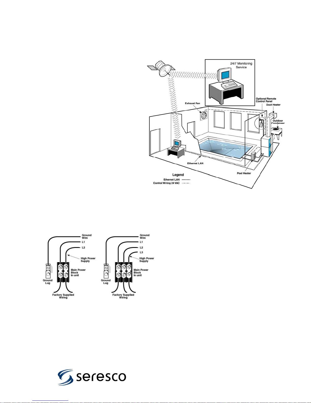
2.3.2 Line Voltage Connections
Figure 7 shows typical power wiring
connections. Single-phase units power
supply must have 3 wires (2 power, 1
ground). On three phase units the power
supply must have 4 wires (3 power, 1
ground). Connect the power supply wires
to the main power block located inside the
electrical panel.
Always check the nameplate voltage before
connecting to the unit.
Figure 7 – Power Wire Connection
2.4. Control Wiring
The NE Series dehumidifiers have all necessary
sensors unit mounted and set points preprogrammed at the factory. Remote duct heaters,
outdoor air-cooled condensers, auxiliary pool water
heaters and remote exhaust fans all require
interfacing with the dehumidifier. Their connection
terminals are identified on page 33
The microprocessor has been programmed to
control their operation. Figure 8 illustrates how an
Ethernet connection to the Internet allows all
functions to be monitored by trained professionals
with Seresco’s Websentry. It is the final step to
ensure the facility operates trouble free.
Figure 8 – Control Wiring
8
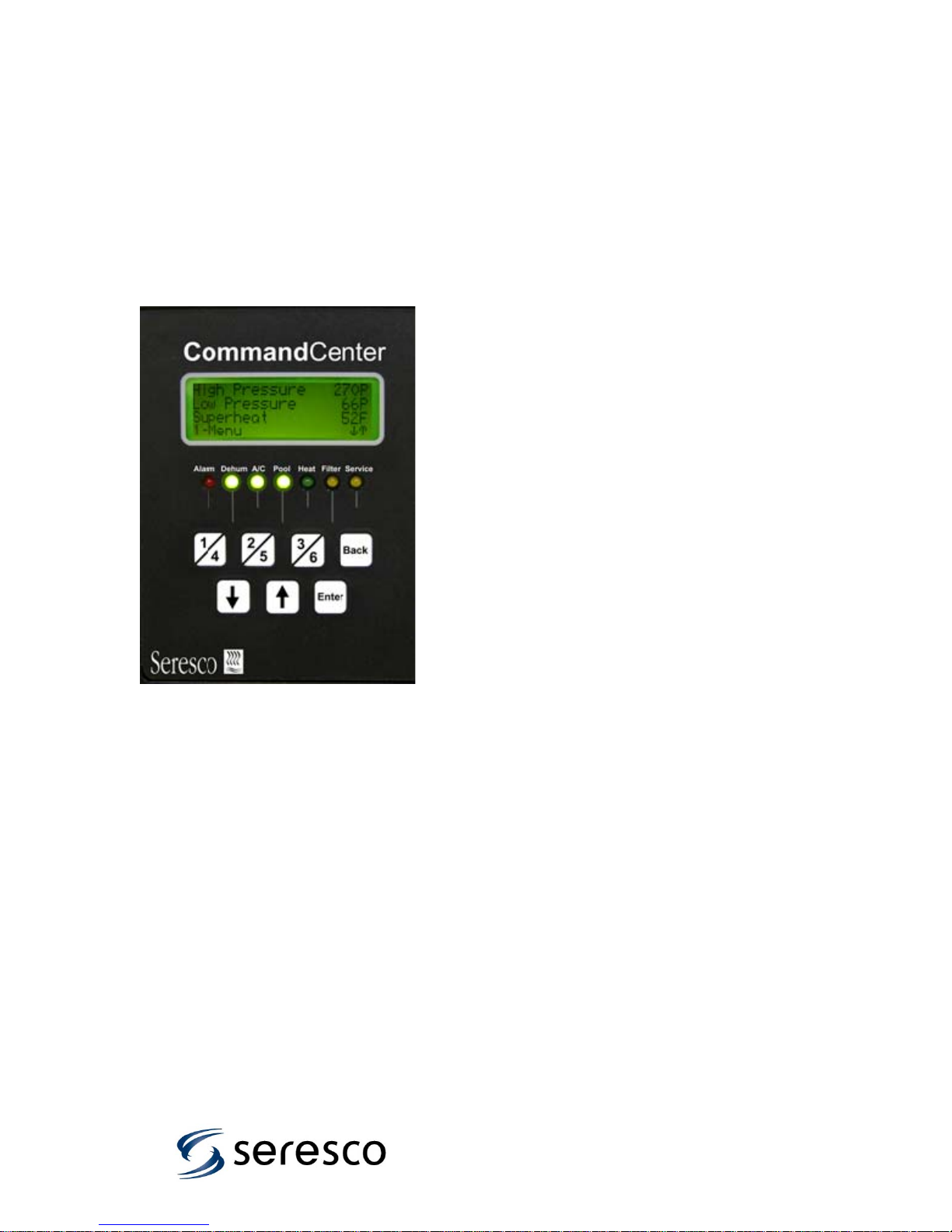
2.5 Controller, Programming and
Sensors
The NE Series Command Center (Figure 9) is
the brains behind the NE Series
Dehumidification System. The Command
Center is composed of a microcontroller
system, an LCD display and keypad, an
Ethernet interface, and WebSentry – a web
browser based remote interface tool for
monitoring and controlling NE Series systems
from anywhere in the world via the internet
Figure 9 – Command Center
The keyboard/display panel is shown in Figure
9 and is located on the NE Series unit at the
mechanical compartment access. The LCD
display has a built-in backlight for easy
reading in low light conditions.
The keys have the following functions:
1, 2, 3 Correspond to numbered selections
4, 5, 6 (menu items and parameters) on the
screen (eg. 1-Menu, press 1for the
main menu)
Back Allows you to return to the previous
menu or cancel a parameter change.
Used for viewing additional
menus, alarms or operating
data and for changing
parameters on the screen such as
setpoints.
Enter Press to save changes to
parameters and (optionally) press
again to return to the main sensor
screen.
There are 7 LEDs as shown and their function
is as follows:
Alarm Solid Red indicates an active alarm
(that has not yet been cleared). A
Flashing Red indicates an alarm that
has not been acknowledged yet.
Dehum Solid Green indicates system is in
dehumidification mode. Compressor
will run when anti-short cycle timer is
satisfied.
A/C Solid Green indicates system is
in air-conditioning mode. Compressor
will run when anti-short cycle timer is
satisfied.
Pool Solid Green indicates that pool
heating is on. If Dehum or A/C is also
on, then heating is by the NE Series
unit. If Dehum and A/C are off,
auxiliary heating is energized.
Heat Solid Green indicates that the
auxiliary air heating system is on.
Filter Solid Yellow indicates that the air
filters are dirty and need changing
(optional only).
Service Solid Yellow indicates that the NE
Series unit is in Service Mode.
Flashing Yellow indicates that the
blower or compressor have been
manually disabled (when not in
Service Mode).
There are two main modes of operation for the
NE Series Units: “Normal Mode” and “Service
Mode”. In normal mode, the user can view
sensor information, view unit operating status,
change setpoints (password protected), adjust
the occupied/unoccupied schedule (password
protected), and view alarms and warnings.
The system operates automatically.
In Service Mode, the trained technician has
access to special features to aid in system
commissioning and troubleshooting, including
Ethernet network access test utilities.
The system operates under manual control.
9

2.5.1 Normal Mode:
Menus and selections are accessed using the “1-6” numbered keys – each menu item and
parameter is preceded by a number from 1 to 6. When the scroll keys can be used to access
additional menu items they will appear on the screen ( and ). The same scroll keys are used to
change values after a parameter has been selected.
A User Password is required to view/change setpoints and schedules. Passwords are 3 digits
long, and entry is done using the scroll keys ( and ) to change the 1
password value – then press Enter to accept that digit and move on to the 2
rd
3
digit. The User password is supplied to the customer under separate cover.
st
digit to the correct
nd
digit, repeat for the
From the main screen, which shows sensor readings, press 1 (-Menu) to open the main menu
structure below. From any menu level, the Back button will return to the previous menu
level without making any changes. Note that some menu items are only visible if the unit
has been configured with that option:
Temperature Room temperature setpoint
Humidity Room relative humidity setpoint
Pool Temp Pool water temperature setpoint
Economizer Outdoor air temperature below which economizer not used
Freezestat Supply air temperature below which Freezestat alarm trips
Purge Supply air temperature below which Purge will stop
Heat Recovery Outdoor air temperature below which heat recovery starts
Schedule Sets occupied/unoccupied state for ventilation control
Time Slot 1-6 There are 6 available time slots that can be established
Weekday None/All/Weekday/Weekend/Monday to Sunday selection
On Time at which occupied status and ventilation begins
Off Time at which unoccupied status begins, ventilation stops
System
Blower/Compressor Enabling/disabling blower and compressor operation
Purge Starts/stops purge 100% ventilation operation
System Restart Manual reset
Alarm Log View Alarms
System Status See Section 2.5.4
System Summary Summary of system configurations
User Settings
Display
Backlight Turn backlight on or off
Reset Display Idle time before display reverts to the main sensor screen
Short Message Time for which short information messages remain visible
Long Message Time for which long information messages remain visible
System Clock
Date Set the date
Time Set the time
Zone Set the time zone
Daylight Set daylight savings on or off manually
Date Format Format the date on the screen
Time Format Format the time on the screen
Synch Synchronize with internet time server (when connected)
User Password
Enabled Enable/disable user password control
Password Change user password
Retention Set time for which password entry remains valid
Factory Settings
Service Mode
Setpoint
Figure 10 Command Center Quick Menu
10

2.5.2 Service Mode
From the Startup Menu there is a Service
Mode available for factory trained service
technicians. Please contact factory for
additional information.
2.5.3 Logs
The CommandCenter logs alarm messages
which can be accessed from the
LCD/Keypad.
Alarm messages are as follows:
HP# -NN High pressure trip (# indicates
compressor, NN can be SW
or TD indicating switch or
transducer alarm)
LP# -NN Low pressure trip (# indicates
compressor, NN can be SW
or TD indicating switch or
transducer alarm)
Blower OL Blower overload trip
No Air Airflow alarm, air pressure
switch (optional) reading too
low air pressure differential
Fire Firestat signal active
Waterflow Low water flow, controls have
detected pool water out
temperature is too high
Filter Dirty filter, filter switch
(optional) reading a high
pressure differential
Pumpdown Compressor pumpdown timed
out (no LP switch detected)
Freeze Freezestat
Purge Supply air too cold during
purge, purge shut down
Volt Mon Voltage monitor
Oil # Oil failure (# indicates
compressor)
No Config System not configured at
startup (only needs to be
done once)
Restart Manual Reset required to start
normal operation
SW Error System has detected an
internal error – contact factory
CompPower Indicates that compressor has
been manually disabled
through an external switch for
an extended period of time
SensorNNN Indicates sensor fault where
NNN identifies the sensor
2.5.4 System Status
The CommandCenter has a feature which
will provide more detailed information about
the internal operation of the system, which
can assist an owner or service technician in
understanding his NE Series unit is doing at
any given moment.
This feature is accessed through the menu
system at /Main Menu/System/System
Status.
The various system elements are broken
into three main groups:
Environment Related to air relative
humidity and temperature
control, pool heating control
Compressor Related to the operation of
the compressors
Other Related to miscellaneous
system operations
Selecting the Compressor elements takes
you to a screen showing the compressor
status, and also which solenoid valves and
contactors are energized. The solenoid
valves and contactors are coded as follows:
PW Compressor contactor
PD Pumpdown valve
DH Dehumidification (reheat) valve
AC Air conditioning valve
PH Pool water heating valve
PB Pool water heating bypass valve
11
 Loading...