

Page 1

®
WirePlus
Installation
and
User Guide
SRC-DOCWPMAN-01-2007 (XTN Ver 1.0)
Preliminary Draft
Page 2

Table of Contents
1 Introducing WirePlus ...........................................1
The WirePlus XTN ........................................................2
2 Quick Start.......................................................... 3
3 Package Verification............................................4
4 Installing XTN Outlets .........................................4
Your WirePlus XTN.......................................................5
Installing Your Outlet ...................................................6
5 Specifications.................................................... 12
XTN Specifications .....................................................12
6 Approvals .......................................................... 14
The FCC wants you to know: ......................................14
Caution: Exposure to Radio Frequency Radiation ....... 15
7 Technical Support .............................................16
8 Troubleshooting Aid .......................................... 17
ii WirePlus Installation and User Guide
Page 3

1 Introducing WirePlus
Thank you for purchasing a SercoNet WirePlus solution.
WirePlus takes you beyond the world of cords and cables, providing you
with a non-invasive, wireless, broadband home network. The WirePlus
system consists of two outlets. The WirePlus INT serves as the basis of
your home wireless network, while WirePlus XTNs extend that network
to every corner of your home.
WirePlus outlets are IEEE 802.11g compliant wireless network
solutions, combining standards based wireless technology with existing
telephone wires already in the home. By combining these features,
Wi-Fi signals can be extended easily, providing you with an easy to
install, affordable, high-speed, home network.
WirePlus outlets leave your existing phone system intact, allowing the
full range of telephony features, such as call forwarding and caller ID,
and telephony hardware such as fax and answering machines.
Additionally, the WirePlus system coexists seamlessly with cable and
DSL services, such as ADSL2++.
In the event of a power outage, WirePlus outlets allow direct access to
the Public Switched Telephone Network (PSTN) via a standard RJ-11
phone connector, supporting lifeline services, and allowing you to place
emergency calls.
Introducing WirePlus 1
Page 4
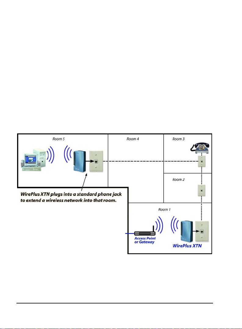
The WirePlus XTN
By plugging WirePlus XTN outlets into telephone jacks throughout your
home you can benefit from full wireless coverage at the highest possible
Wi-Fi speeds. Normally, as distance from the transmitting antenna of
the wireless access point (WAP) increases, walls and interference cause
signal levels to decrease, or result in dead spots. It brings 0 or 1 bars of
signal strength to 4 or 5 bars.
The XTN outlet overcomes these issues and provides robust
performance wherever needed by boosting signal strength. By bringing
the antenna closer to the workstation, the XTN ensures that your
broadband services operate near the maximum 802.11b/g throughput
all the time.
Figure 1: Typical XTN Application
2 Introducing WirePlus
Page 5

2 Quick Start
If you are experienced with hardware and networking, you can use the
Quick Start section to set up your WirePlus solution. If you are not
experienced with hardware and networking, skip the Quick Start and go
to Chapter 3.
To install your WirePlus outlets:
1. Set the channel selector on the back of the outlet using a
small screwdriver (not provided). The channel is obtained
from the WAP or via client software in the remote
computer.(see Figure 3).
2. Slightly loosen the screws on your telephone jack, slide the
plastic base into place, and retighten the screws (see figure
4).
Note:
You do not need to completely remove the screws.
3. Connect the outlet to the telephone jack (see Figure 5).
4. Snap the outlet into the plastic base (see Figure 6).
5. Switch the antenna on (see Figure 7).
6. Attach the power supply (see Figure 8).
Note:
If you are installing an XTN, your installation is complete.
Quick Start 3
Page 6

3 Package Verification
Unpack your WirePlus outlet and ensure all the components are
present. Your package should include one of the following combinations
of components:
Table 1: Package Contents
XTN Package
2 XTN Outlets
2 Plastic Base Units
2 AC/DC Power
Adapters
Installation manual
Installing XTN Outlets
If you are installing a WirePlus XTN outlet, select an installation
location in the area you need to boost your network’s signal strength
(See figure 1).
The channel you select when installing an XTN outlet will be the
channel for your wireless network. The rotary dial (see Figure 3) on all
outlets in your network must be set to the same channel as your
network. If you are unsure of what channel to select, see the channel
set in the software of the WAP or if provided from the client software
with the client computer (associated with your network SSID).
4 Package Verification
Page 7
The first unit must be installed in close proximity to the WAP. Ideally it
should be within 1-2 meters. There should not be any walls, metal
cabinets, mirrors or other wireless (RF) limiting structure between the
first XTN and WAP.
There may be multiple dead or low speed spots in the building. Multiple
remote XTN’s can be used. Ideally an XTN should be located at the
nearest telephone jack to the location were the dead spot is. XTN’s
should be located no closer than 10 meters (30 feet) to each other if
there are no walls or obstacles between units. Always start with XTN
units set to the lowest power setting.
When adjusting the antenna setting adjust 1 unit at a time to obtain
optimal function.
If you must change channels make sure you power down (unplug) the
unit before attempting linkage to the WAP.
Note:
If you are adding an XTN to an existing network you must set the
XTN to the same channel as your network.
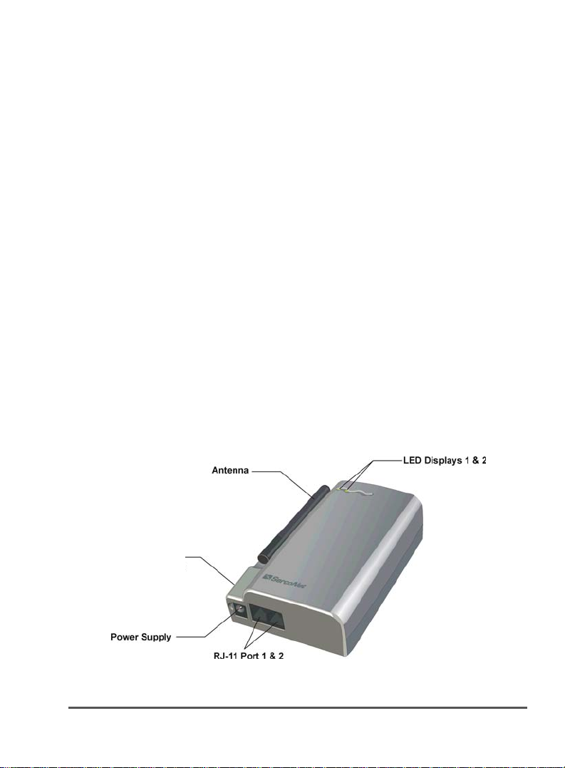
Your WirePlus XTN
Figure 2 shows the interface, connectors, and LEDs of your XTN.
Antenna
High/Low
switch
Figure 2: XTN Interface, Connectors, and LEDs
Installing XTN Outlets 5
Page 8

Note:
LEDs are numbered from left to right.
Table 2 lists the XTN LEDs and their functions.
Table 2: XTN LEDs
LED Activity
LED 1: Power Lights green when the power supply is connected
LED 2: Wireless Flashes green when there is wireless (RF) traffic.
Light will flash as bright as power light with high
traffic is present.
Installing Your Outlet
To install your WirePlus XTN:
1. Set the rotary dial on the back of your outlet to the channel
of your network.
Rotary dial
Figure 3: Rotary Dial
6 Installing XTN Outlets
Page 9

Channel selector
WiFi channel XTN rotary
Channel 1-9 Channel 1-9
Channel 10 Channel A
Channel 11
Channel B
Channel 12
Channel 13
Channel 14
Not used
Not used
Channel C
Channel D
Channel E
Channel F
Channel 0
1. Disconnect the phone cord from the jack, if you have DSL also
disconnect the ADSL filter from the jack.
2. Slightly loosen the screws on your telephone jack’s wall
plate and slide the lip of the plastic base behind the
telephone jack’s wall plate, and pull the plastic base down
over the wall plate.
Note:
You do not need to completely remove the screws.
Installing XTN Outlets 7
Page 10

Figure 4: Mounting The Base
3. Tighten the screws on the telephone jack’s wall plate.
8 Installing XTN Outlets
Page 11
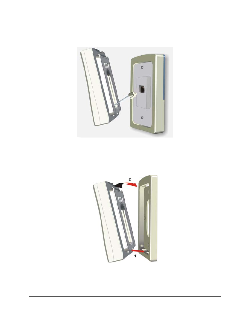
4. Plug the outlet into the telephone jack using the RJ-11
adapter on the back of the outlet.
Figure 5: Connecting With RJ-11
5. Insert the tabs on the bottom of the outlet into the slots on
the bottom of the base (1); then press the outlet flat
against the base until it snaps into place (2).
Figure 6: Mounting The Outlet
Installing XTN Outlets 9
Page 12

w
6. Antenna High/Low Switch – selects power transmission
and receives sensitivity levels. Default settings are Low for
reduced radiation. Set to High for a better coverage area.
Note: If the antenna switch is in High position the
distance between the XTN’s must be at least 10 meters
(30 feet).
Antenna High/Lo
Figure 7: Antenna High/Low Switch
Note:
The antenna is in the Low position when the switch is pushed
towards the rear panel of the outlet.
10 Installing XTN Outlets
Page 13

w
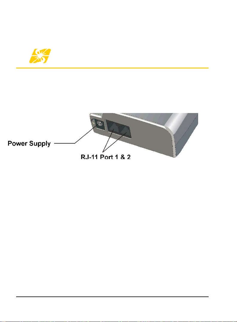
7. Connect the AC/DC power adapter to your WirePlus outlet
and then plug it into a power outlet.
8. Reconnect the ADSL filter if used into port 1 of the XTN
unit; then the phone line into the filter. If no DSL plug the
phone line into port 1 directly. Port 2 would be used for a
second line of a 2 line phone set.
Antenna High/Lo
Figure 8: Power Supply
Installing XTN Outlets 11
Page 14
5 Specifications
Technical specifications for SercoNet’s WirePlus XTN outlets follow:
XTN Specifications
Figure 9: Power Supply and phone jack layout
12 Specifications
Page 15

Table 3: XTN Specifications
INT IEEE-802.11g
Standards IEEE-802.11g, IEEE-802.11b
Channels 11 Channels (US and Canada)
Telephony Interface
Connections 2 x RJ-11
Telephony
Functionality
Regulatory
Regulatory
Parameters
Integrated Outlet 4.8 x 1.5 x 3.0 inches
Outlet Base 4.8 x 0.7 x 3.0 inches
Operating
Temperature
Operating Humidity 0-85% RH non-condensing
Storage Temperature -4°F to 158°F
Power Input: 5VDC
13 Channels (Europe)
14 Channels (Japan)
Regular Telephone Sets
Dial-Up Modems
Fax Machines
Speakerphones
Answering Machines
Caller ID
xDSL
123 x 37 x 78 mm
123 x 17.5 x 78 mm
32°F to 104°F
0°C to 40°C
-20°C to 70°C
Consumption: 2.5 Watts
Specifications 13
Page 16

6 Approvals
The FCC wants you to know:
This equipment has been tested and found to comply with the limits for
a Class B digital devise, pursuant to Part 15 of the FCC rules. These
limits are designed to provide reasonable protection against harmful
interference in a residential installation. This equipment generates, uses
and can radiate radio frequency energy and, if not installed and used in
accordance with the instructions, may cause harmful interference to
radio communications. However, there is no guarantee that interference
will not occur in a particular installation. If this equipment does cause
harmful interference to radio or television reception, which can be
determined by turning the equipment off and on, the user is encouraged
to try to correct the interference by one of more of the following
measures:
a. Reorient or relocate the receiving antenna.
b. Increase the separation between the equipment and receiver.
c. Connect the equipment to an outlet on a circuit different from
that to which the receiver is connected.
d. Consult the dealer or an experienced radio/TV technician.
14 Approvals
Page 17

Caution: Exposure to Radio Frequency
Radiation
The radiated output power of this devise is far below the FCC radio
frequency exposure limits. Nevertheless, the device shall be used in
such manner that the potential for human contact normal operation is
minimized. When connecting an external antenna to the device, the
antenna shall be placed in such a manner to minimize the potential for
human contact during normal operation. In order to avoid the
possibility of exceeding the FCC radio frequency exposure limits, human
proximity to the antenna shall not be less than 20cm (8 inches) during
normal operation.
Note:
This equipment complies with 47CFT Part 68 of the Rules.
This equipment complies with TUV60950-1
The manufacturer is not responsible for any Radio or TV
Note:
interference caused by unauthorized modifications to this eqipment.
Such modifications could void the User’s authority to operate the
equipment.
This product may be covered by one or more of the following U.S.
Note:
Patents: 5,841,360; 6,690,677; 6,970,538; 6,549,616; 6,757,368;
7,123,701; 6,842,459; 6,961,303; 6,927,340; 7,109,418; 7,016,368;
7,035,280; 7,006,523 ; 7,095,756 ;6,956,826
Other U.S. and International Patents Pending.
Approvals 15
Page 18

7 Technical Support
If you need further assistance with the installation or operation of your
WirePlus outlet, please contact SercoNet Technical Support at one of
the following telephone or fax numbers, Email address, or website:
North America
Toll Free: 800-508-7646
Office: 727-490-4248
Fax: 727-490-2300
Mobile:
International
Tel: +972-9-7411833
Fax: +972-9-7481333
Email: support@serconet.net
Website: www.serconet.net
16 Technical Support
TBD
Page 19

8 Troubleshooting Aid
Item Trouble Fix
1 No LED’s lighted on
unit
2 Power LED OK
No flashing LED
3 Power LED OK.
No flashing LED
4 LED is flashing,
limited bars on
computer
5 LED’s seem to
working but no
traffic
6 LED’s are flashing,
computer sees
other SSID’s on
same channel.
7 LED on right
flashing, but no
traffic
Verify that the power outlet is working.
Should not be controlled by a light
switch.
Verify that you have the correct channel
on all units.
Verify that the RJ-11 cable is correctly
seated in the jack.
Verify that the wall jack is wired
correctly. Use phone to verify dial tone.
Adjust power setting to high level at one
or all XTN units
Verify WAP is working. Can the
computer access WEB with correct
SSID in same room as the WAP? If not
bad WAP.
Reset network for another channel.
Channels 1,6,11 are the only three nonoverlapping channels
Units are too close together
Troubleshooting Aid 17
Page 20

18 Troubleshooting Aid
 Loading...