

The Driver in Embedded Service – Oriented Home Networking Systems
SRC-DOC10MANWAP06-2003
NetHome
TM
NH10WAP11b
IEEE-802.11b Wireless Access Point
User Guide

Table of Contents
1. INTRODUCTION...........................................................................................................................................................3
1.1. THE NETHOME SOLUTION ..........................................................................................................................................3
1.1.1. Flexible Interfacing..........................................................................................................................................3
1.1.2. Broadband Service Providers’ Extended Reach..........................................................................................3
1.2. NETHOME WIRELESS ACCESS POINT..........................................................................................................................4
1.3. BENEFITS....................................................................................................................................................................4
1.4. IMPLEMENTING THE NETHOME WIRELESS ACCESS POINT ADAPTER...........................................................................4
2. INSTALLATION.............................................................................................................................................................5
2.1. WHAT’S IN THE BOX?................................................................................................................................................5
2.1.1. The NetHome Wireless Access Point Adapter...............................................................................................6
2.2. INSTALLING THE NETHOME WIRELESS ACCESS POINT................................................................................................7
3. OPERATION.................................................................................................................................................................10
4. SOFTWARE CONFIGURATION .............................................................................................................................11
4.1. CONFIGURING THE WIRELESS ACCESS POINT ............................................................................................................11
4.1.1. Finding the IP address of the Wireless Access Point Adapter..................................................................14
4.2. CONFIGURING MULTIPLE WIRELESS ACCESS POINTS.................................................................................................15
4.3. CONFIGURING A PC TO COMMUNICATE WITH THE WIRELESS ACCESS POINT...........................................................16
5. TROUBLESHOOTING...............................................................................................................................................16
5.1. REPLACING A FAULTY WIRELESS ACCESS POINT ADAPTER ......................................................................................17
6. SPECIFICATIONS.......................................................................................................................................................18
A. APPROVALS.................................................................................................................................................................19
A.1. FCC / PART 15 COMPLIANCE STATEMENTS..........................................................................................................19
A.1.1 FCC / PART 15 Notification...........................................................................................................................19
A.1.2 FCC / PART 15 Compliance Conditions:.....................................................................................................19
A.1.3 FCC / PART 15 Declaration Of Conformity regarding the Wireless Access Point
(WAP) Unit, Model SRC-10AP802B:........................................................................................................................20
A.1.4 FCC / PART 15 Warning regarding the Wireless Access Point (WAP) Unit, Model SRC-10AP802B:20
A.2. FCC / PART 68 COMPLIANCE STATEMENTS..........................................................................................................21
A.2.1 Customer Information Statement..................................................................................................................21
A.2.2 FCC / PART 68 Product Label Sample and Statement...............................................................................21
A.2.3 FCC / PART 68 FIC/SOC Codes for Analog Equipment Facility Interface Codes and
Service Order Code....................................................................................................................................................22
2
1. INTRODUCTION
The NH10WAP11b - NetHome™ IEEE-802.11b Wireless Access Point adapter enables the NetHome™ Ethernet based
home backbone system to communicate with multiple wireless devices using standard IEEE-802.11b protocol.
This guide describes how to install a NetHome Wireless Access Point adapter, establish a wireless network, and configure the
access point to securely communicate with multiple wireless devices.
For general information about implementing a NetHome system and setting up a network of NetHome Smart Outlets, refer to
the SercoNet Smart Outlet™ Network Technical User Guide.
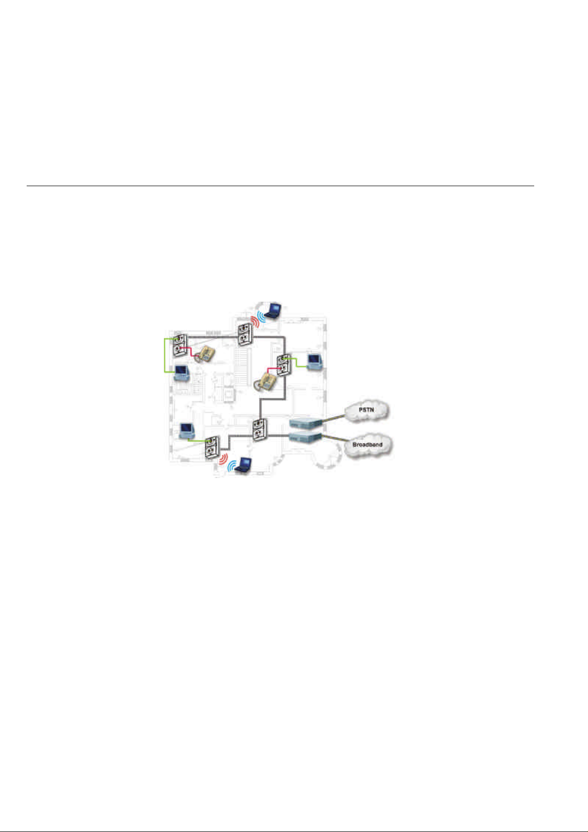
1.1. The NetHome Solution
The SercoNet NetHome network solution distributes residential and SOHO broadband communication to devices such as
PCs, printers, and scanners. The system uses existing phone wires to deliver free-flowing, uninterrupted data, voice, and video
streams at broadband speeds. Simply replacing the home phone jacks with SercoNet Smart Outlets™ automatically creates a
home 10Mbps Ethernet LAN backbone over the home phone wires. This new backbone guarantees the NetHome network’s
high bandwidth and allows the customer to run multimedia applications alongside data services. In addition, customers need
not worry about losing telephone services, since the NetHome system maintains intact telephone services during power
outages.
Figure 1.1. NetHome Smart Outlet Network Diagram
1.1.1. Flexible Interfacing
The NetHome network features various physical interfaces to connect multiple home device types without extra protocol or
interface converters. The NetHome Smart Outlet has the dominant standard 10BaseT interface, enabling customers to directly
connect multiple home devices to the NetHome network’s backbone. Beyond 10BaseT, the NetHome network supports other
standard interfaces like IEEE-802.11b, providing maximum device connectivity and flexibility via interchangeable parts.
1.1.2. Broadband Service Providers’ Extended Reach
The NetHome network suits a wide spectrum of customers:
• Home users who want to share broadband service.
• Installers seeking easy broadband provision.
• Broadband service providers wishing to sell new value-added services over the NetHome network.
NetHome’s house-wall service point enables broadband providers to redefine the border between the customer and service
provider domains. Thus, NetHome integrates the home broadband backbone with the provider’s service equipment. This fusing
of the home backbone with the broadband service provider’s remote-controlled home-networked applications increases
customer loyalty and reduces customer churn.
Also, by using NetHome, broadband service providers can provide maintenance and support for their customers’ home
networking services, a one-stop-shop transparency that paying customers expect and value.
3

1.2. NetHome Wireless Access Point
The NetHome Wireless Access Point adapter employs the IEEE-802.11b standard for wireless communication. The
NetHome Wireless Access Point adapter enables portable devices to be connected to the same Broadband backbone with
maximum mobility and accessibility.
A NetHome Wireless Access Point can be located at any location in the house that has a phone outlet. This means that you
can position the NetHome Wireless Access Point in the location that gives you the optimal coverage. You do not have to
position the access point in the same location as your broadband connection.
Multiple NetHome Wireless Access Points can be connected where one Access Point cannot provide the required coverage.
The robust performance of the wired system enables communication between multiple Access Points without compromising
the performance.
1.3. Benefits
Benefits of the Wireless Access Point adapter include:
• Integrated wired and wireless solutions for home coverage.
• Choice of ideal Access Point location for enhanced performance.
• Communication between multiple Access Points.
• Mobility of portable devices maintained alongside wired connections to desktop devices.
• Enhanced security of the wired segments of the system.
1.4. Implementing the NetHome Wireless Access Point Adapter
NetHome Smart Outlet slots into the NetHome Wireless Access Point adapter, and the resultant unit replaces a standard
phone jack. No new wires are required. You do not need to connect the NetHome Wireless Access Point adapter to a power
outlet.
4

2. Installation
This chapter describes how to install a NetHome Smart Outlet with the Wireless Access Point adapter. The NetHome Smart
Outlet should be installed in a network with the SercoNet Power Unit and any other necessary SercoNet NetHome products,
as described in the SercoNet Smart Outlet Network Technical User Guide.
Possible topology scenarios for NetHome Smart Outlets are described in the SercoNet Smart Outlet Network Technical
User Guide. The Wireless Access Point adapter can be used to adapt any NetHome Smart Outlet in the network.
2.1. What’s in the Box?
SercoNet’s NH10WAP11b - NetHomeIEEE-802.11b Wireless Access Point installation kit is shipped with the following
items:
• The NetHome Wireless Access Point adapter.
• CD containing this user guide and IP locator software.
• 2 mounting screws.
5
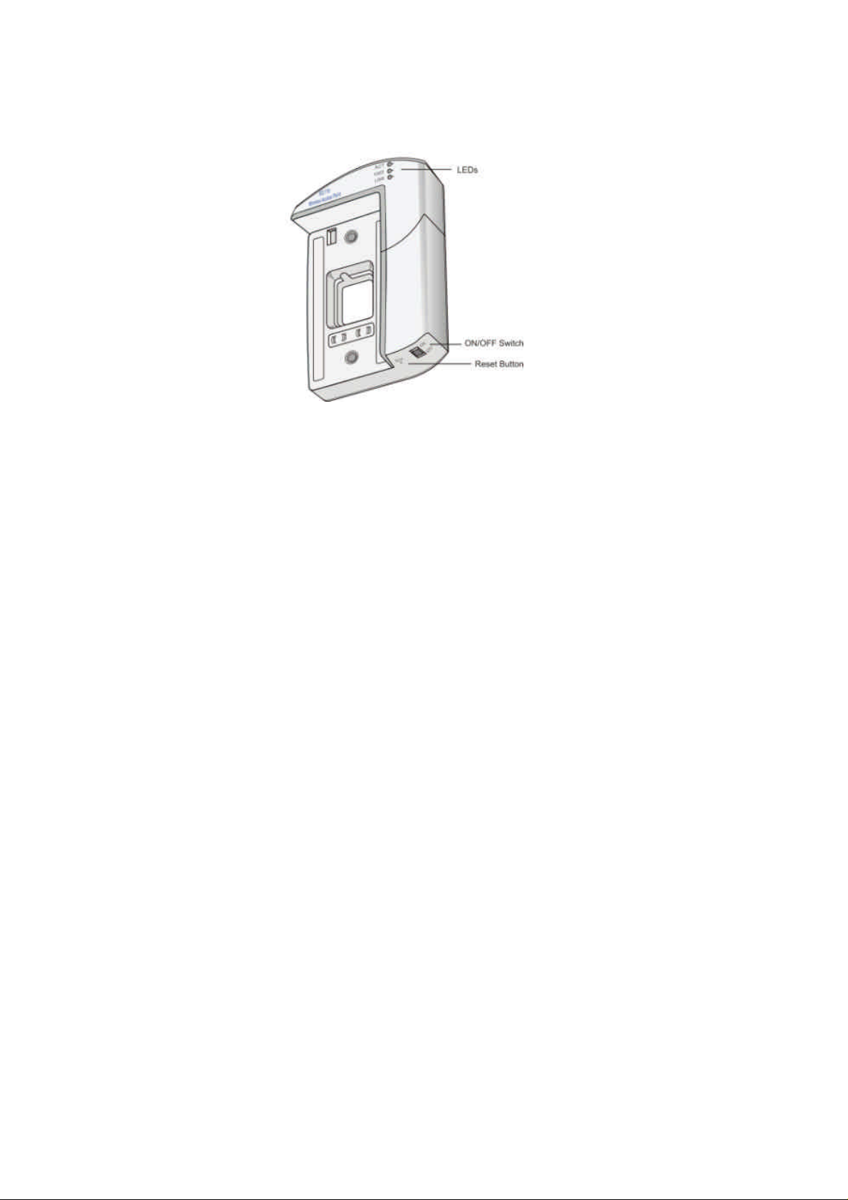
2.1.1. The NetHome Wireless Access Point Adapter
Figure 2.1 shows the NetHome Wireless Access Point adapter.
Figure 2.1 The NetHome Wireless Access Point Adapter
The Wireless Access Point adapter has the following features:
• LEDs – indicate power status and traffic on the access point.
• ON/OFF Switch – enables you to switch the access point off when not in use, saving energy and improving security.
• Reset Button – enables you to reset the configuration of the access point using a thin non-metallic object.
6
2.2. Installing the NetHome Wireless Access Point
Installation of the NetHome Smart Outlet with the Wireless Access Point adapter is simple and requires no special tools. All
you need is a screwdriver.
If you want to use a Wireless Access Point adapter with an existing NetHome network, you will need to remove one of the
Smart Outlets in the network and reinstall that Smart Outlet with the Wireless Access Point adapter.
To install a NetHome Smart Outlet with the Wireless Access Point adapter:
1. If you already have an operational NetHome Smart Outlet network, disconnect the power cord from your SercoNet power
unit to deactivate the network.
Caution: Do not plug the power cable from the NetHome power unit into the AC power outlet until the NetHome
network installation is complete.
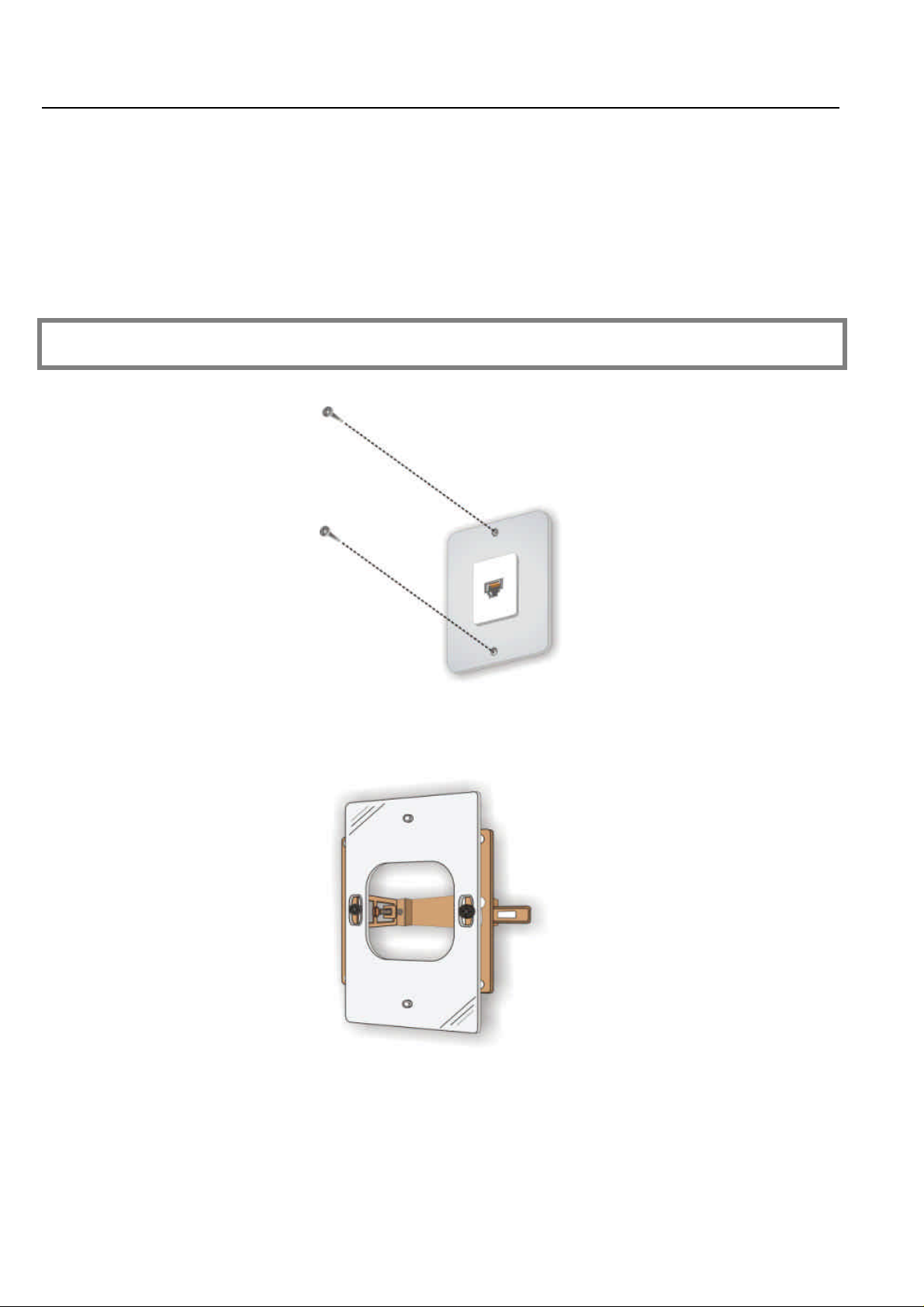
2. Remove either the regular phone jack (Figure 2.2) or pre-installed NetHome Smart Outlet from the wall.
Figure 2.2 Removing a Phone Jack
3. Disconnect the wiring from the rear of the phone jack or NetHome Smart Outlet that you just removed.
4. If you are using a European outlet, insert the supplied adapter plate in place of the outlet you removed (Figure 2.3).
Figure 2.3 European Adapter Plate
5. Connect the wire pair from the Wireless Access Point adapter to terminal block connector P1, P2, or P3 on the rear
panel of the NetHome Smart Outlet (refer to Figure 2.4). To connect each wire to a terminal, loosen the screw of the
terminal, and then insert the wire into the corresponding slot. Fasten the screw to hold the wire in place.
7
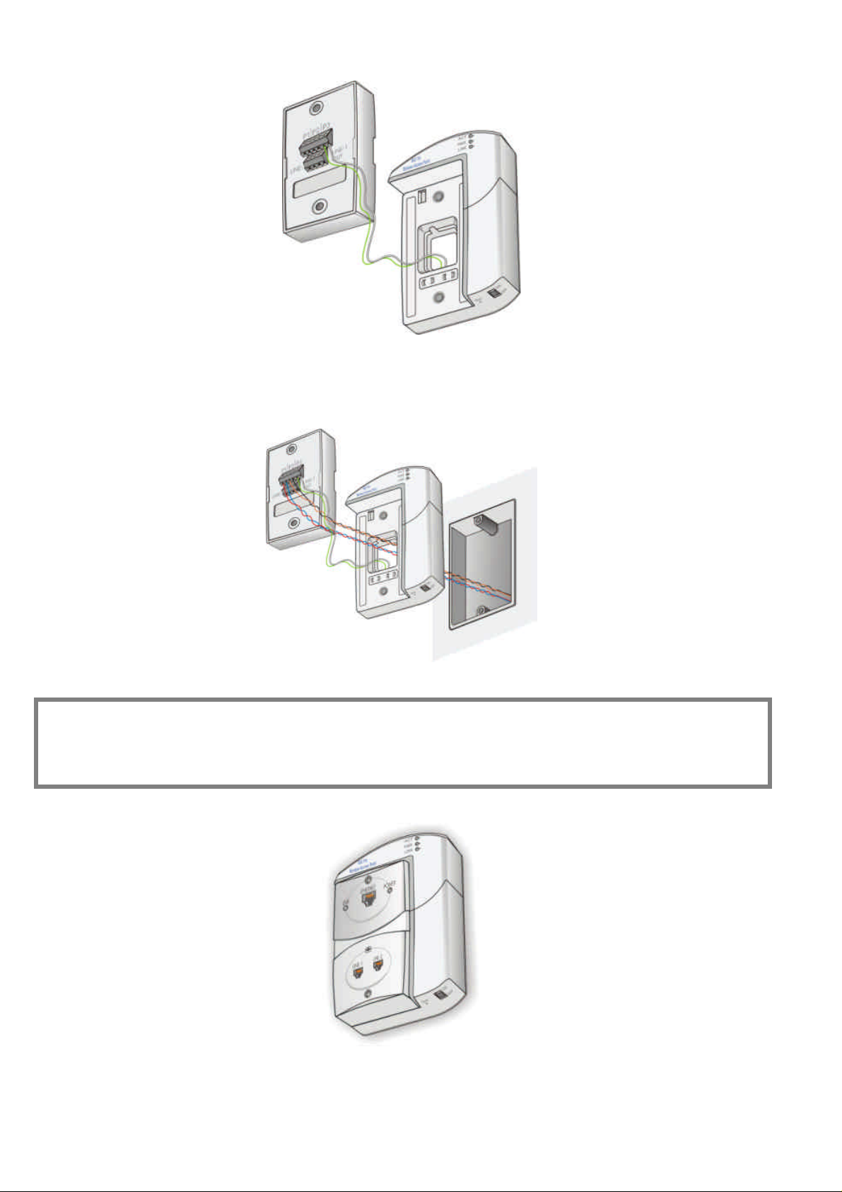
Figure 2.4 Connecting the Wireless Access Point Adapter to the NetHome Smart Outlet
6. Thread the phone wire pairs through the hole in the Wireless Access Point adapter from the back to the front, and
connect each wire pair to a remaining terminal block connector P1, P2, or P3 in the rear panel of the NetHome Smart
Outlet (refer to Figure 2.5).
Figure 2.5 Connecting the Phone Wires to the NetHome Smart Outlet
Note: Make sure to keep wires in a pair juxtaposed. The polarity and sequence of wire pairs within a terminal block is
not important.
In rare cases, some phone sets are polarity sensitive. If the phone set does not function as previously, try switching the
wires within each pair.
7. Fit the NetHome Smart Outlet into the Wireless Access Point adapter (refer to Figure 2.6).
Figure 2.6 The NetHome Smart Outlet Slotted into the Wireless Access Point Adapter
8. Screw the NetHome Smart Outlet and Wireless Access Point adapter into the wall, using the mounting screws provided
(refer to Figure 2.7).
8

Figure 2.7 Screwing the Wireless Access Point into the Wall
9. Reconnect the power cord to your NetHome power unit to restore operation of your NetHome network.
The NetHome Smart Outlet is now installed with the Wireless Access Point adapter.
9

3. OPERATION
The NetHome Wireless Access Point adapter features an on/off switch so that you can deactivate the access point when not in
use. Switching the access point off when not in use increases security and saves energy.
To operate the access point, make sure that the network is powered, by checking that the power cord is plugged into the
SercoNet power unit, and switch the on/off switch (refer to Figure 2.1 on page 6) to the ON position.
If the installation was successful, the LEDs on the NetHome Wireless Access Point adapter front panel operate as described
in Table 3.1.
LED Description
POWER Lights green
ACT Flashes yellow whenever there is wireless
(RF) traffic on the Access Point.
LINK Lights yellow when there is Ethernet traffic
between the Access Point and the NetHome
Ethernet backbone.
Table 3.1 Front Panel LEDs
10

4. SOFTWARE CONFIGURATION
4.1. Configuring the Wireless Access Point
This section describes the basic software configuration you need to perform to start using your access point for wireless
communication. To perform the software configuration, you need a PC with an internet browser and an Ethernet cable.
To configure the NetHome Wireless Access Point:
1. Connect the PC to the Ethernet port of any of the NetHome Smart Outlets on the same network as the Wireless Access
Point, using the Ethernet cable.
2. Open an Internet browser on the PC.
3. Verify that the Wireless Access Point adapter is switched on.
4. Type the IP address of the Wireless Access Point adapter into the Address box, as shown in Figure 4.1. Refer to Finding
the IP address of the Wireless Access Point Adapter on page 14 for information about how to find the IP address of the
Wireless Access Point adapter.
Figure 4.1 Internet Browser Address box
The Enter Network Password dialog box opens (Figure 4.2).
Figure 4.2 Enter Network Password Dialog Box
5. Enter your user name and password in the appropriate fields. By default, the user name and password are blank. If you
don’t remember the user name and password, press the reset button on the Wireless Access Point adapter with a thin
non-metallic object (refer to Figure 2.1 on page 6). This restores the user name and password to their default, blank
values.
6. Press OK. The 802.11b Access Point configuration application opens.
7. Click the Wireless tab. The Wireless Configuration screen appears (Figure 4.3).
11

Figure 4.3 Wireless Configuration Screen
8. In the SSID box, enter an SSID of your choice, or leave the default text “WAP” as the SSID. The SSID is arbitrary, but in
order for any two devices on the network to communicate with each other, they must be assigned the same SSID. The
SSID is case sensitive and limited to 30 characters.
9. From the Channel drop-down box, select the radio channel on which the access point will send and receive data. The
default channel is 6. The channel range available depends on your country (refer to Table 4.1).
Area Standard Permissible
Channels
US FCC 1-11
Europe ETSI 1-13
Japan MKK 13-14
Table 4.1 Channeling Standards
10. Click Save to save your wireless configuration settings.
11. Click the IP Addr tab. The Server Configuration screen appears (Figure 4.4).
Figure 4.4 Server Configuration Screen
12. Select the IP Address Mode:
• Static – the IP address is to be assigned manually.
• DHCP – the IP address is provided automatically by a DHCP server.
13. If the IP Address Mode is set to Static, enter the default IP address to be used by the access point (default: 192.168.0.8.)
into the Default IP address field.
12

14. Click Save to save your server configuration settings.
Note: If the IP address is changed, the Wireless Access Point must be switched off and on again before the new IP
address can be used. Alternatively, press Reboot in the Administration screen (refer to Figure 4.6 on page 14).
15. Click the Security tab. The Security screen appears (Figure 4.5).
Figure 4.5 Security and Encryption Settings Screen
16. In the AP Visibility area, set the Visibility Status to Visible or Invisible. The default is Visible. Setting the AP to Invisible
disables the SSID from being broadcast by the AP. If you set the Visibility Status to Invisible, any client device will need
to be configured with the same SSID as the access point in order to communicate with the access point. This feature
prevents users from finding your AP, unless you provide them the SSID to connect.
17. In the WEP configuration area, check the WEP enabled checkbox if you want to enable WEP (Wireless Encryption
Protection). WEP is a standard for encrypting data to protect your wireless network from unauthorized access. When
WEP is enabled, the device can only communicate with another device configured with the same WEP code.
18. If you checked WEP enabled, set the following parameters:
• WEP key lengths – select a WEP code length from the WEP key lengths drop down box.
• WEP key 1, WEP key 2 … – enter a hexadecimal string code in at least one WEP key box. If you set the WEP key
length to 64 bits, you must enter 10 hexadecimal characters. If you set the WEP key length to 128 bit, you must enter
26 hexadecimal characters.
• WEP key to use – select which WEP key to use for transmitted data.
Note: Hexadecimal characters include digits in the range 0-9 and characters A-F.
19. Click Save to save your security settings.
20. Click the Admin tab. The Administration screen appears (Figure 4.6).
13

Figure 4.6 Administration Screen
21. If you want to restrict the privilege of configuring the access point, set the following parameters:
• User name – enter a user name of your choice. Anyone user wishing to re-enter this application to modify the access
point configuration will need to enter this user name in the Enter Network Password dialog box, shown in Figure 4.2
on page 11.
• Administrator password – enter a password of your choice. Anyone user wishing to re-enter this application to
modify the access point configuration will need to enter this password in the Enter Network Password dialog box,
shown in Figure 4.2 on page 11. Re-enter the same password in the box below for password confirmation.
22. Click Save to save your administration settings.
4.1.1. Finding the IP address of the Wireless Access Point Adapter
You need the IP address for accessing the web-based configuration application. Once you have accessed the application, you
can change the IP address mode in the Server Configuration screen.
The Wireless Access Point adapter is preconfigured in one of two IP address modes:
• Static – the IP address is to be assigned manually. The default is 192.168.0.8.
• DHCP – the IP address is provided automatically by a DHCP server.
The CD shipped in the installation kit provides Device IP Locator software. You can use Device IP Locator to find the IP
address of the Wireless Access Point adapter in cases where the preset IP address mode is DHCP or in cases where you
don’t know the preset IP address mode. You can also use the Device IP Locator to change the IP address.
To find the IP address of the Wireless Access Point adapter:
1. Install Device IP Locator by double clicking first on the "UbicomUCP.dll" icon followed by a double click on the
"Locator" icon
1. Verify that the Wireless Access Point adapter is switched on.
2. Connect the PC to the Ethernet port of any of the Smart Outlets on the same NetHome network as the Wireless Access
Point, using the Ethernet cable.
3. Open the Device IP Locator. The Device IP Locator Window opens (Figure 4.7).
14

Figure 4.7 The Device IP Locator Window
4. Click the Scan toolbar button. The software scans for the IP address of the Wireless Access Point adapter. When the scan
is complete, the Wireless Access Point is listed in the window, and its IP address is displayed in the IP address column.
If the IP address mode is preset to DHCP and there is no active DHCP server available in the same network, the Wireless
Access Point adaptor IP address is automatically assigned the default value of 0.0.0.0. This IP address is invalid. In this case,
change the IP address to a valid IP address using the Device IP Locator. You can also use the Device IP Locator to change a
valid IP address to another valid IP address.
To change the IP address of the Wireless Access Point:
1. Select the Wireless Access Point in the list.
2. Click the Configure toolbar button. The IP Address Properties dialog box opens (Figure 4.8).
Figure 4.8 IP Address Properties dialog box
3. Click Use the following IP address.
4. Type the IP address and Subnet mask you would like to use.
5. Click Apply.
4.2. Configuring Multiple Wireless Access Points
SercoNet’s NetHome system supports more than one wireless access point on the same network. Since the coverage of the
wireless access points may overlap, each Wireless Access Point adapter must be configured with the same SSID but with
different operation channel to prevent interference between them (refer to Figure 4.9). It is recommended to choose
channels that are farther apart for better spectrum separation.
Figure 4.9 Multiple Wireless Access Points with Overlapping Coverage Areas
15

4.3. Configuring a PC to Communicate with the Wireless Access Point
When you have installed a NetHome Smart Outlet with the Wireless Access Point adapter, and configured the access point as
described in section 4.1, any wireless device, such as a laptop computer, fitted with a Wireless Network Card can
communicate with the access point via the NetHome Wireless Access Point adapter. Consult your Wireless Network Card
user manual for instructions for configuring the card for communication with your network.
Desktop devices can be physically connected to the NetHome Smart Outlet via a CAT 5 cable, in the same way as with any
other Smart Outlet in your NetHome network.
Note: On each wireless device communicating with the Wireless Access Point, the following parameters should be set
to be identical to the settings of the same parameters on the Wireless Access Point itself:
♦ SSID
♦ WEP length and code (if enabled)
♦ Channel – most wireless access clients auto sense the channel.
♦ Network type – should be Infrastructure
5. TROUBLESHOOTING
This section provides solutions to try in the event of various troubleshooting scenarios.
The POWER LED on the Wireless Access Point adapter is not lit
The Wireless Access Point adapter is not powered. Try the following:
• Make sure the ON/OFF switch of the Wireless Access Point adapter is in the ON position.
• Verify that the POWER LED lit on the other Smart Outlets on the same network. If only one of the Smart Outlets is not
powered, refer to the SercoNet Smart Outlet Network Technical User Guide.
• If the POWER LED on the Smart Outlet is lit but the POWER LED on the Wireless Access Point adapter is not lit,
check the twisted pair wiring connection between the Wireless Access Point adapter and the attached Smart Outlet. Make
sure the wires are properly connected to P1, P2, or P3 terminal blocks at the back of the Smart Outlet.
• If the Wireless Access Point adapter is properly wired and switched ON, and the POWER LED is still not lit, replace the
Wireless Access Point adapter with another.
The LINK LED on the Wireless Access Point adapter is not lit
The LINK LED indicates an Ethernet connection between the Wireless Access Point adapter and the attached Smart Outlet. If
the LINK Led does not light:
• Make sure the ON/OFF switch of the Wireless Access Point adapter is in the ON position.
• Check that the POWER LED of the Smart Outlet is lit.
• Make sure the wires are properly connected between the Wireless Access Point adapter and P1, P2, or P3 terminal
blocks at the back of the Smart Outlet.
• Press the RESET button with a sharp pin to reset the Wireless Access Point adapter. Use the web-based configuration
application to return the system parameters to the desired setting.
• If after performing the above steps, the LINK LED does not light, replace the Wireless Access Point adapter with
another.
A wireless device cannot communicate through the SercoNet Wireless Access Point adapter
There are various possible causes of failure in wireless communication between a wireless device and the SercoNet Wireless
Access Point adapter. Some of these causes are beyond the scope of this user guide, such as hardware or configuration issues
relating to the wireless device. The following are list of recommended steps taken in order to make sure that the SercoNet
Wireless Access Point adapter is properly configured and function.
• Make sure that the wireless device supports IEEE-802.11b wireless transmission protocol.
• Verify that the ACT LED is lit.
• Verify that the SSID is the same on the Wireless Access Point adapter and on the wireless device.
16

• Verify that the WEP code is enabled or disabled on both Wireless Access Point adapter and the wireless device. If WEP
is enabled, make sure that both devices are using the same WEP code.
• Verify that the Wireless Access Point adapter operation channel matches the operation channel that the wireless device
supports.
• Make sure the ON/OFF switch of the Wireless Access Point adapter is in the ON position.
• Press the RESET button with a sharp pin to reset the Wireless Access Point adapter. Use the web-based configuration
application to return the system parameters to the desired setting.
• Verify that the wireless device is properly configured and functioning.
• Check that the Wireless Access Point adapter can communicate with a different wireless device.
• If after performing the above steps there is no wireless communication, replace the Wireless Access Point adapter with
another.
5.1. Replacing a Faulty Wireless Access Point Adapter
If you need to replace a faulty Wireless Access Point adapter, do the following:
1. Disconnect the power cord from your SercoNet power unit to deactivate the network.
2. Remove the NetHome Smart Outlet together with the Wireless Access Point adapter from the wall.
3. Disconnect the wiring from the rear of the phone jack or NetHome Smart Outlet and the Wireless Access Point adapter
that you just removed.
4. Follow steps 4-9 in Installing the NetHome Wireless Access Point on page 7.
The NetHome Smart Outlet is now installed with the new Wireless Access Point adapter. Using the web-based configuration
application, verify that the new adapter has the same configuration as the previous faulty adapter.
17

6. SPECIFICATIONS
Power 6 watts (equivalent to 2 NH10SO)
Regulatory UL, CUL, FCC B, CE
Wireless Interface Description
Standard IEEE-802.11b
Frequency band 2.4 ~ 2.4835 GHz (subject to local regulation)
Spreading spectrum
standard
Security (North
America)
Operation range Up to 300 feet (100 meters)
Supported bit rate 11Mbps, 5.5Mbps, 2Mbps, 1Mbps Automatic
Effective throughput 5.5Mbps
Active users support 32
Modulation 11Mbps and 5.5Mbps: CCK; 2Mbps: DQPSK;
Number of channels USA and Canada – 11 Europe - 13
Transmit power (North
America)
Antenna system Dual antenna diversity system 2dB gain
Network Management Description
DSSS (Direct Sequence Spread Spectrum)
64 and 128 bit WEP
Scale Fallback Functionality
1Mbps: DBPSK
France - 4 Japan – 1
19.9 dBm
Standard DHCP, ICMP, Web server
Management utility Web based
Network protocols
support
NetHome Interface Description
Standard NetHome (integrated power and Ethernet on
Connection
Mechanical Description
Dimensions (H x D x W) 6.28” x 1.57” x 4.65”
Weight (approximate) 400 gr. (est.)
Operating Temperature 32F to 104F
Operating Humidity 0-85% RH non-condensing
Storage Temperature -4F to 158F
TCP/IP, IPX, NDIS3, NDIS4, NetBEUI
single pair)
1 twisted pair
160 x 40 x 118 mm
0 to 40 C
-20C to 70C
18

A. Approvals
A.1. FCC / PART 15 Compliance Statements
A.1.1 FCC / PART 15 Notification
The FCC Wants You to Know
This equipment has been tested and found to comply with the limits
for a Class B digital device, pursuant to Part 15 of the FCC rules.
These limits are designed to provide reasonable protection against
harmful interference in a residential installation. This equipment
generates, uses and can radiate radio frequency energy and, if not
installed and used in accordance with the instructions, may cause
harmful interference to radio communications. However, there is no
guarantee that interference will not occur in a particular
installation. If this equipment does cause harmful interference to
radio or television reception, which can be determined by turning
the equipment off and on, the user is encouraged to try to correct the
interference by one or more of the following measures:
a.) Reorient or relocate the receiving antenna.
b.) Increase the separation between the equipment and receiver.
c.) Connect the equipment to an outlet on a circuit different from
that to which the receiver is connected.
d.) Consult the dealer or an experienced radio/TV technician.
FCC Warning
Modifications not expressly approved by the manufacturer could
void the user authority to operate the equipment under FCC Rules.
Tested To Comply With FCC Standards
FOR HOME OR OFFICE USE
A.1.2 FCC / PART 15 Compliance Conditions:
This device complies with Part 15 of the FCC Rules.
Operation is subject to the following two conditions:
(1) This device may not cause harmful interference, and
(2) This device must accept any interference received, including interference that may cause undesired
operation.
19

A.1.3 FCC / PART 15 Declaration Of Conformity regarding the Wireless Access Point (WAP)
Unit, Model SRC-10AP802B:
FCC Declaration Of Conformity
We, the undersigned,
Company: SercoNet Inc.
Address: Deerfoot Office Park, 257 Turnpike Road, Suite 340, Southborough,
MA 01772
Country: U.S.A.
Telephone Number: 508-229-3670
Fax Number: 508-229-3671
are the Responsible Party for this Declaration, certify and declare under our sole responsibility that the following
equipment:
Brand Type(model) Product Description
NetHomeTM IEEE-802.11b
Wireless Access Point
of Smart Outlet System
complies with Part 15 of the FCC Rules.
Operation is subject to the following two conditions:
(1) this device may not cause harmful interference, and
(2) this device must accept any interference received, including interference that may cause undesired operation.
Date:
Company Stamp:
Signature:
Name and Function:
A.1.4 FCC / PART 15 Warning regarding the Wireless Access Point (WAP) Unit, Model SRC-10AP802B:
The antenna used for this transmitter must be installed to provide a separation distance of at least 20 cm from
all persons and not be co-located or operating in conjunction with any other antenna or transmitter.
SRC-10AP802B 2.4 GHz Wireless Access Point (WAP)
for LAN Ethernet
20

A.2. FCC / PART 68 Compliance Statements
Responsible Party Name: SerCoNet Ltd.
A.2.1 Customer Information Statement
General Requirements for ALL Equipment:
1. This equipment complies with 47 CFR, Part 68 of the rules.
On the rear side of the SRC-POWERU, SRC-10MPS and SRC-10FRST Units of this equipment is a label that contains,
among other information, the certification number and ringer equivalence number (REN) for this equipment. If
requested, this information must be provided to the telephone company.
2. The Application Certification Jack USOC (Universal Service Order Code) used for the equipment is RJ11C.
3. A compliant telephone cord and modular plug is provided with this equipment. This equipment is designated to be
connected to the telephone network or premises wiring using a compatible modular jack which is Part 68 compliant. See
installation instructions for details.
4. If the terminal equipment Smart Outlet System causes harm to the telephone network, the telephone company will
notify you in advance that temporary discontinuance of service may be required. But if advance notice is not practical,
the telephone company will notify the customer as soon as possible. Also, you will be advised of your right to file a
complaint with the FCC if you believe it is necessary.
5. The telephone company may make changes in it’s facilities, equipment, operations, or procedures that could affect the
operation of the equipment. If this happens the telephone company will provide advance notice in order for you to make
the necessary modifications to maintain uninterrupted services.
6. If trouble is experienced with this equipment Smart Outlet System, for repairs or warranty information, please contact
SercoNet Inc., Deerfoot Office Park, 257 Turnpike Road, Suite 340, Southborough, MA 01772,
Tel. 508-229-3670, Fax. 508-229-3671. If the equipment is causing harm to the telephone network, the telephone
company may request that you disconnect the equipment until the problem is resolved.
7. No repairs can be performed on the Smart Outlet System by the customer (user).
8. The equipment cannot be used on public coin phone services provided by the telephone company. Connection to party
line services is subject to state tariffs. Contact the state public utility commission, public service commission, or
corporate commission for information.
A.2.2 FCC / PART 68 Product Label Sample and Statement
The following is a Short Form representative drawing of the FCC / ACTA Label for the Model SRC-POWERU that appears
at the rear side of the Model SRC-POWERU:
Certification Number: US: AAAHN05BSI010
Model Number: SRC-POWERU
The Complete Form of the above label appears below, as follows:
Complies with 47 CFR Part 68
Certification Number: US: AAAHN05BSI010
Ringer Equivalence Number: 0.5B
Made in Israel
Use USOC Jack: RJ11C
• V indicates the Vendor / Manufacturer Name.
• YY indicate two digits, ranging from 00 to 99, for the Year.
• WW indicate two digits, ranging from 00 to 54, for the Week.
• SSSSS indicate five digits, ranging from 00000 to 99999, for the Serial Number.
21
The structure of the Serial Number appearing at the
above label is as follows:

A.2.3 FCC / PART 68 FIC/ SOC Codes for Analog Equipment Facility Interface Codes and Service Order
Code
FIC Codes for Analog Equipment:
Applies (x)
√√
-
-
-
-
-
-
-
-
FIC Codes Description
02LS2 2-Wire, Local Switched Access, Loop-Start
02GS2 2-Wire, Local Switched Access, Ground-Start
02RV2-0 2-Wire, DID, Customer Originates (only for E911
02RV2-T 2-Wire, Local Switched Access, Reverse Battery,
*04LS2 4-Wire, Local Switched Access, Loop-Start
*04GS2 4-Wire, Local Switched Access, Ground-Start
*04RV2-T 4-Wire, Local Switched Access, Reverse Battery,
02LR2 2-Wire, Private Line Automatic Ring-down
04LR2 4-Wire, Private Line Automatic Ring-down
* Subject to local availability
Identification Service)
Customer Term, DID Ports
Customer Termination
22

SOC Code for Analog Equipment:
Applies (x)
√√
-
-
-
SOC Codes
9.0F Provides full protection to the Network from systems
9.0N Unprotected systems. Requires use of registered
9.0Y Provides full Part 68 protection. Provides signal
7.0Y Provides total protection to the network for
Description
using live voices.
Only registered terminal equipment can be connected
to station ports.
protective couplers or filing of affidavits with the
telco. See Section 68.215 (d) and (e).
limiting for all signal sources
(not just MOH)
connection for private communication systems.
23

Copyright © SercoNet, all rights are reserved. NetHome and Smart Outlet are registered trademarks of SercoNet.
Microsoft Windows 98 (WIN98), Windows ME, Windows 2000 (WIN2000), and Windows NT are trademarks of the
Microsoft Corporation. All other trademarks are registered trademarks or trademarks of their respective holders. All
specifications are subject to change without notice.
24

International Headquarters
SercoNet Ltd.
16 Ha'haroshet St
Ra'anana 43657
Israel
Tel: +972-9-7411833 Tel: (508) 229-3670
Fax: +972-9-7481333 Fax: (508) 229-3671
E-mail: marketing@serconet.net Web Site: www.serconet.net
North America Headquarters
SercoNet Inc.
257 Turnpike Road, Suite 340
Southborough, MA 01772
Toll-free: 1-800-396-9887
25
 Loading...