

Page 1
Advanced Features
fields.
Log This determines whether packets covered by this rule are logged. Select
the desired action.
• Always - always log traffic considered by this rule, whether it
matches or not. (This is useful when debugging your rules.)
• Never - never log traffic considered by this rule, whether it matches
or not.
• Match - Log traffic only it matches this rule. (The action is deter-
mined by this rule.)
• Not Match - Log traffic which is considered by this rule, but does not
match (The action is NOT determined by this rule.)
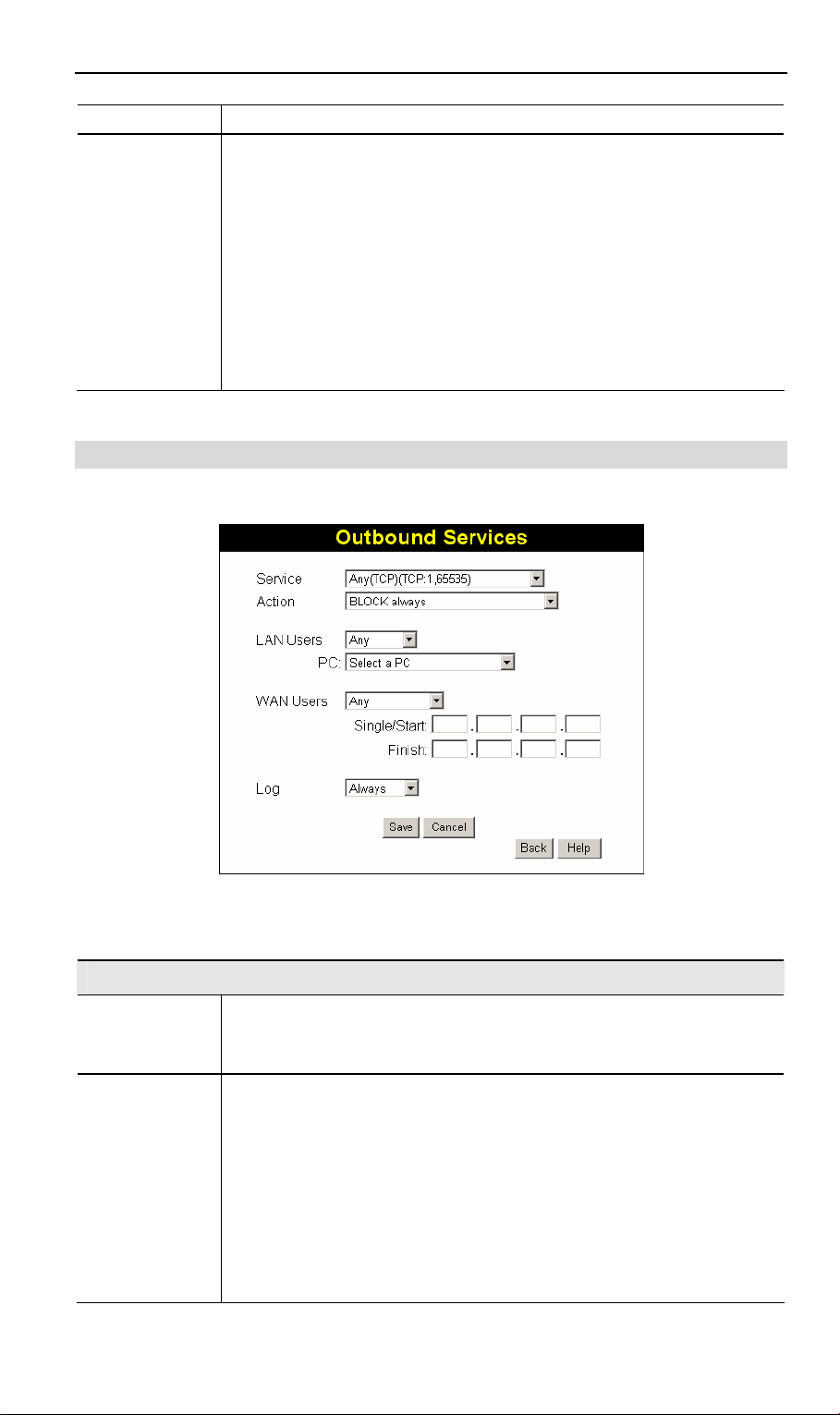
Outgoing Rules (Outbound Services)
This screen is displayed when the "Add" or "Edit" button for Outgoing Rules is clicked.
Figure 46: Outbound Services Screen
Data - Outbound Rules Screen
Outbound Services
Service
Action
Select the desired Service or application to be covered by this rule. If the
desired service or application does not appear in the list, you must define
it using the "Services" menu option
Select the desired action for packets covered by this rule:
• BLOCK always
• BLOCK by schedule, otherwise Allow
• ALLOW always
• ALLOW by schedule, otherwise Block
Note:
• Any outbound traffic which is not blocked by rules you create will
be allowed by the Default rule.
57
Page 2

802.11g ADSL VoIP Gateway User Guide
• ALLOW rules are only useful if the traffic is already covered by a
BLOCK rule. (That is, you wish to allow a subset of traffic which is
currently blocked by another rule.)
• To define the Schedule used in these selections, use the "Schedule"
screen.
LAN Users
WAN Users
Log
Select the desired option to determine which PCs are covered by this rule:
• Any - All PCs are covered by this rule.
• Single PC - Only the selected PC is covered by this rule.
If selected, you must select the PC.
PC - If using Single PC above, select the PC or Server on your LAN
which will be covered by this rule.
These settings determine which packets are covered by the rule, based
on their source (WAN) IP address. Select the desired option:
• Any - All IP addresses are covered by this rule.
• Address range - If this option is selected, you must enter the "Start"
and "Finish" fields.
• Single address - Enter the required address in the "Single/Start"
fields.
This determines whether packets covered by this rule are logged. Select
the desired action.
• Always - always log traffic considered by this rule, whether it
matches or not. (This is useful when debugging your rules.)
• Never - never log traffic considered by this rule, whether it matches
or not.
• Match - Log traffic only it matches this rule. (The action is deter-
mined by this rule.)
• Not Match - Log traffic which is considered by this rule, but does not
match (The action is NOT determined by this rule.)
58
Page 3
Advanced Features
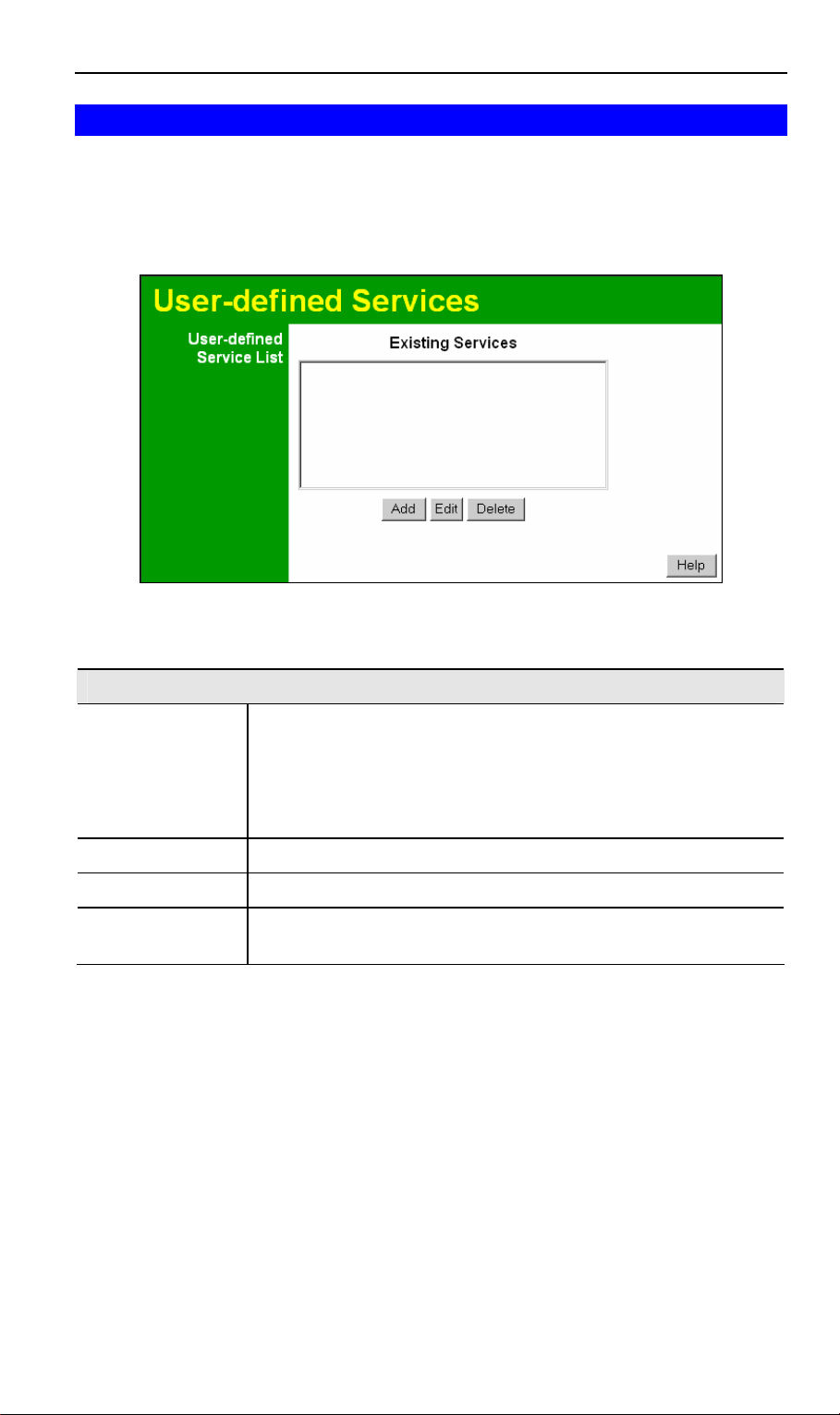
User-defined Services
Services are used when creating Firewall Rules.
If you wish to create a firewall rule, but the required service is not listed in the "Service" list,
you can use this feature to define the required service or services. Once created, these services
will be listed in the "Service" list, and can be used when creating Firewall Rules.
Figure 47: Add Services Screen
Data - User-defined Services
Services
Existing Services This lists any Services you have defined. If you have not defined any
Services, this list will be empty.
Once you define some services, they will be listed here, and also
shown in the Service list used to create Firewall rules. (User -defined
services are at the end of the list, after the pre-defined services.)
Add Use this to open a sub-screen where you can add a new service.
Edit To modify a service, select it, and then click this button.
Delete Use this button to delete the selected service. You can delete any
services you have defined.
59
Page 4
802.11g ADSL VoIP Gateway User Guide
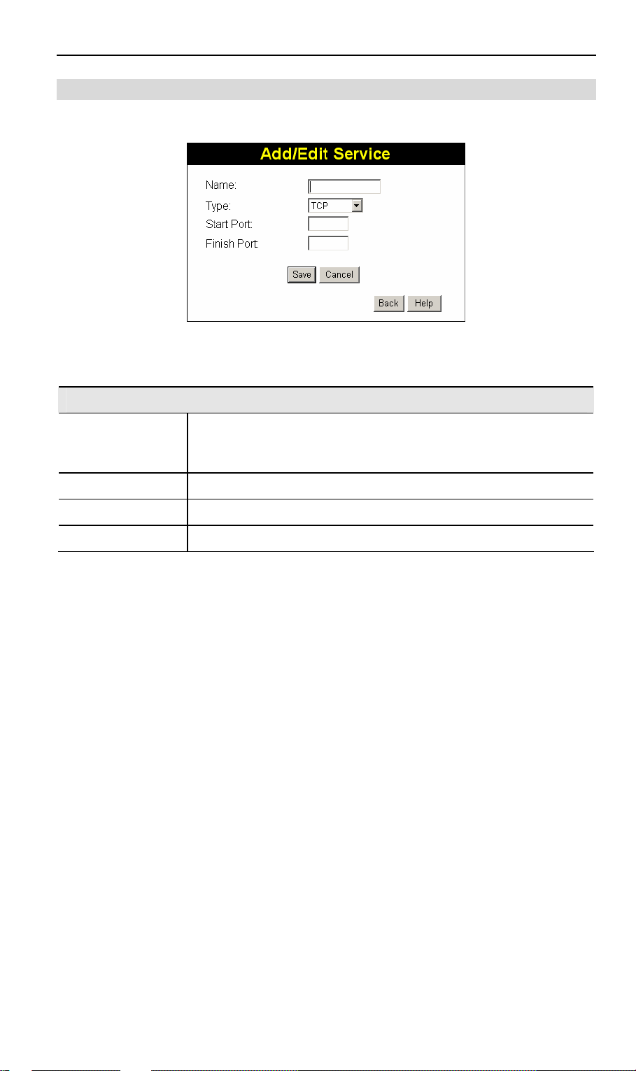
Add/Edit Service
This screen is displayed when the Add or Edit button on the Services screen is clicked.
Figure 48 : Add/Edit Service
Data - Add/Edit Service
Services
Name If editing, this shows the current name of the Service.
If adding a new service, this will be blank, and you should enter a
suitable name.
Type Select the protocol used by the Service.
Start Port Enter the beginning of the port range used by the Service.
Finish Port Enter the end of the port range used by the Service.
60
Page 5
Advanced Features
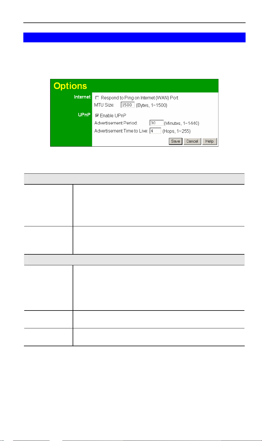
Options
This screen allows advanced users to enter or change a number of settings. For normal oper ation, there is no need to use this screen or change any settings.
An example Options screen is shown below.
Figure 49: Options Screen
Data - Options Screen
Internet
Respond to Ping • If checked, the Wireless Router will repond to Ping (ICMP) packets
received from the Internet.
• If not checked, Ping (ICMP) packets from the Internet will be
ignored. Disabling this option provides a slight increase in security.
MTU Size Enter a value between 1 and 1500.
Note: MTU (Maximum Transmission Unit) size should only be changed
if advised to do so by Technical Support.
UPnP
UPnP • UPnP (Universal Plug and Play) allows automatic discovery and
configuration of equipment attached to your LAN. UPnP is by
supported Windows ME, XP, or later.
• If Enabled, this device will be visible via UPnP.
• If Disabled, this device will not be visible via UPnP.
Advertisement
Period
Advertisement
Time to Live
Enter the desired value, in minutes. The valid range is from 1 to 1440.
Enter the desired value, in hops. The valid range is from 1 to 255.
61
Page 6
802.11g ADSL VoIP Gateway User Guide
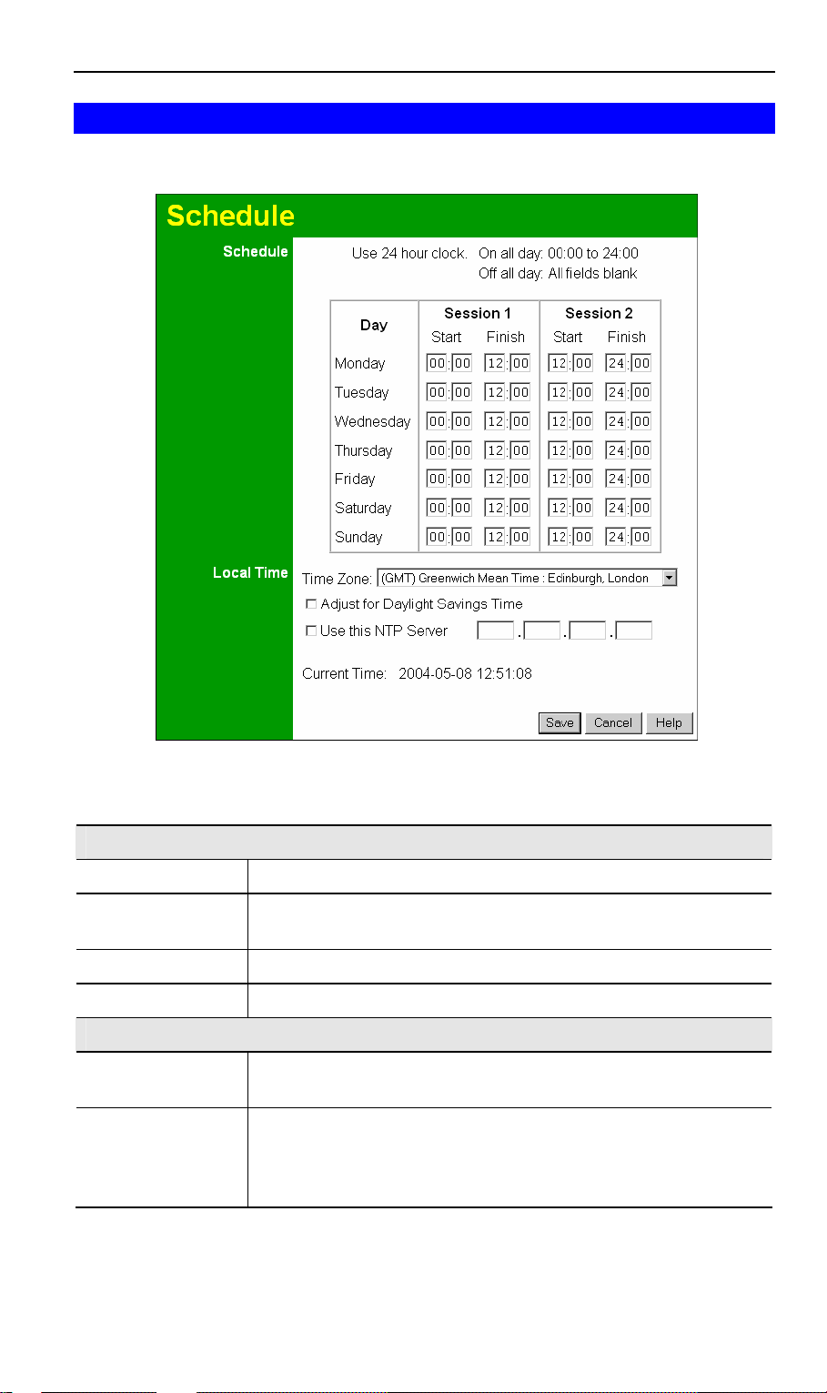
Schedule
This Schedule can be used for the Firewall Rules and the URL filter.
Figure 50: Schedule Screen
Data - Schedule Screen
Schedule
Day Each day of the week can scheduled independently.
Session 1
Session 2
Start Time Enter the start using a 24 hr clock.
Finish Time Enter the finish time using a 24 hr clock.
Local Time
Time Zone In order to display your local time correctly, you must select your
Adjust for Daylight
Savings Time
Two (2) separate sessions or periods can be defined. Session 2 can
be left blank if not required.
"Time Zone" from the list.
If your region uses Daylight Savings Time, you must manually check
"Adjust for Daylight Savings Time" at the beginning of the adjustment period, and uncheck it at the end of the Daylight Savings
period.
62
Page 7

Advanced Features
Use this NTP Server If you prefer to use a particular NTP server as the primary NTP
server, check the checkbox "Use this NTP Server" and enter the
Server's IP address in the fields provided..
If this setting is not enabl ed, the default NTP Servers are used.
Current Time This displays the current time on the 802.11g ADSL VoIP Gateway, at
the time the page is loaded.
63
Page 8
802.11g ADSL VoIP Gateway User Guide
Virtual Servers
This feature, sometimes called Port Forwarding, allows you to make Servers on your LAN
accessible to Internet users. Normally, Internet users would not be able to access a server on
your LAN because:
• Your Server does not have a valid external IP Address.
• Attempts to connect to devices on your LAN are blocked by the firewall in this device.
The "Virtual Server" feature solves these problems and allows Internet users to connect to your
servers, as illustrated below.
Figure 51: Virtual Servers
IP Address seen by Internet Users
Note that, in this illustration, both Internet users are connecting to the same IP Address, but
using different protocols.
To Internet users, all virtual Servers on your LAN have the same IP Address. This
IP Address is allocated by your ISP.
This address should be static, rather than dynamic, to make it easier for Internet users to connect to your Servers.
However, you can use the DDNS (Dynamic DNS) feature to allow users to connect to your
Virtual Ser vers using a URL, instead of an IP Address.
Virtual Servers Screen
• The "Virtual Servers" feature allows Internet Users to access PCs on your LAN.
• The PCs must be running the appropriate Server Software.
64
Page 9
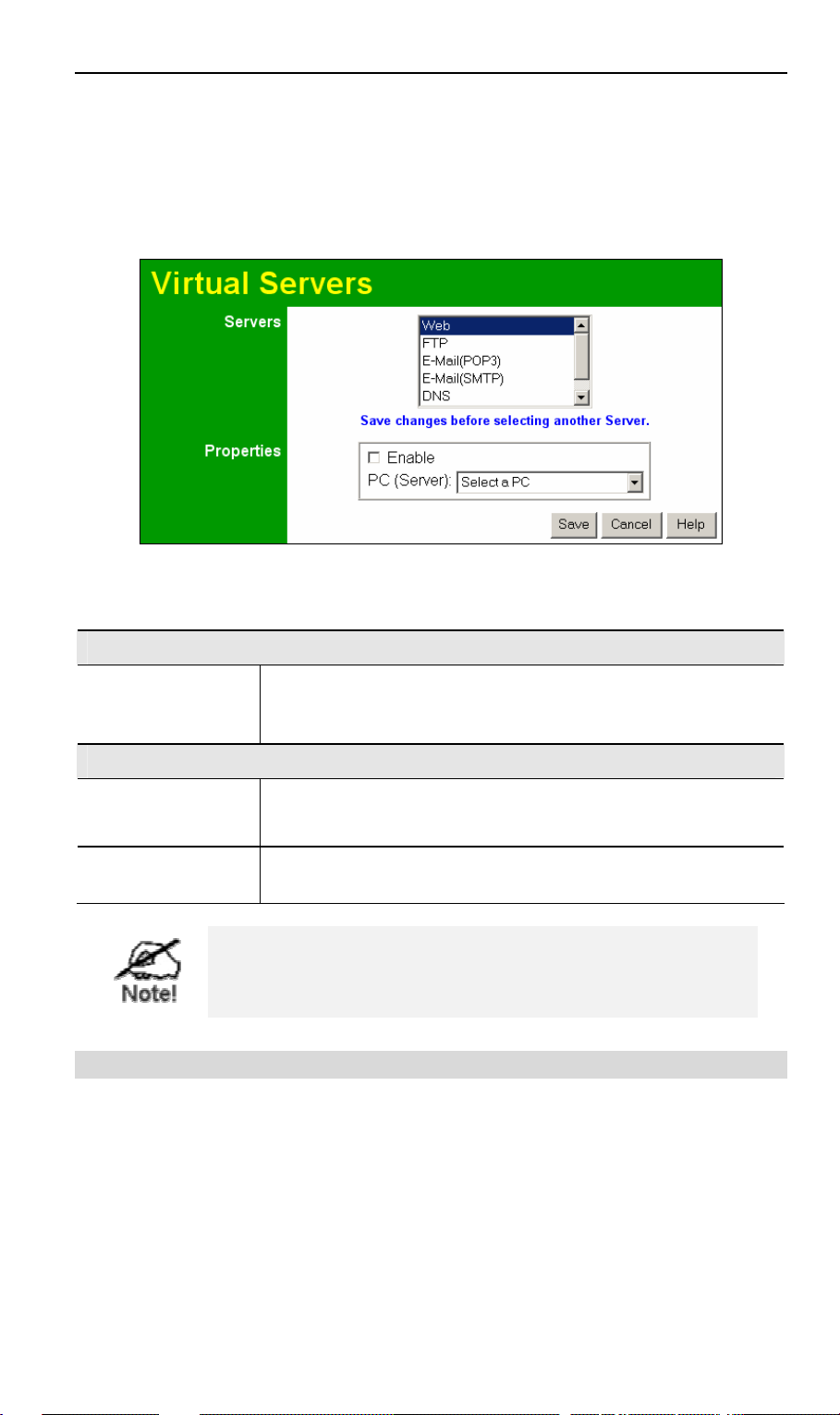
Advanced Features
• For Internet Users, ALL of your Servers have the sa me IP address. This IP address is
allocated by your ISP.
• To make it easier for Internet users to connect to your Servers, you can use the "DDNS"
feature. This allows Internet users to connect to your Servers with a URL, rather than an IP
address. This technology works even if your ISP allocates dynamic IP addresses (IP address is allocated upon connection, so it may change each time you connect).
Figure 52: Virtual Servers Screen
Data - Virtual Servers Screen
Servers
Servers This lists a number of common Server types. If the desired Server
type is not listed, you can create a Firewall Rule to achieve the same
effect as the Virtual Server function.
Properties
Enable Use this to Enable or Disable support for this Server, as required.
If Enabled, you must select the PC to which this traffic will be sent.
PC (Server) Select the PC for this Server. The PC must be running the appr opri-
ate Server software.
For each entry, the PC must be running the appropriate
Server software. If the desired Server type is not listed, you
can define your own Servers, using the Firewall Rules.
Connecting to the Virtual Servers
Once configured, anyone on the Internet can connect to your Virtual Servers. They must use
the Internet IP Address (the IP Address allocated to you by your ISP).
e.g.
http://203.70.212.52
ftp://203.70.212.52
It is more convenient if you are using a Fixed IP Address from your ISP, rather than Dynamic.
However, you can use the Dynamic DNS feature to allow users to connect to your Virtual
Servers using a URL, rather than an IP Address.
65
Page 10

802.11g ADSL VoIP Gateway User Guide
Note:
From the Internet, ALL Virtual Servers have the IP Address allocated by your ISP.
66
Page 11
Advanced Features
VoIP
To use the VoIP feature requires the following:
• Standard Phone
A standard analogue Phone must be connected to the Phone socket.
• VoIP (SIP Server) Account
Generally, you will need a SIP Server account from a VoIP service provider. The account details should include the SIP Register address, SIP Proxy address, SIP register port, SIP
Proxy port, username, password and telephone number. (Many providers use the same
proxy server for both Proxy and Register.)
• VoIP Configuration
• Your VoIP service provider may perform the configuration for you.
• If not, refer to the following sections, which describe how to conf igure the Wireless
VoIP Gateway.
Refer to Chapter 7 - Operation and Status for details on using VoIP once configuration has
been com pleted.
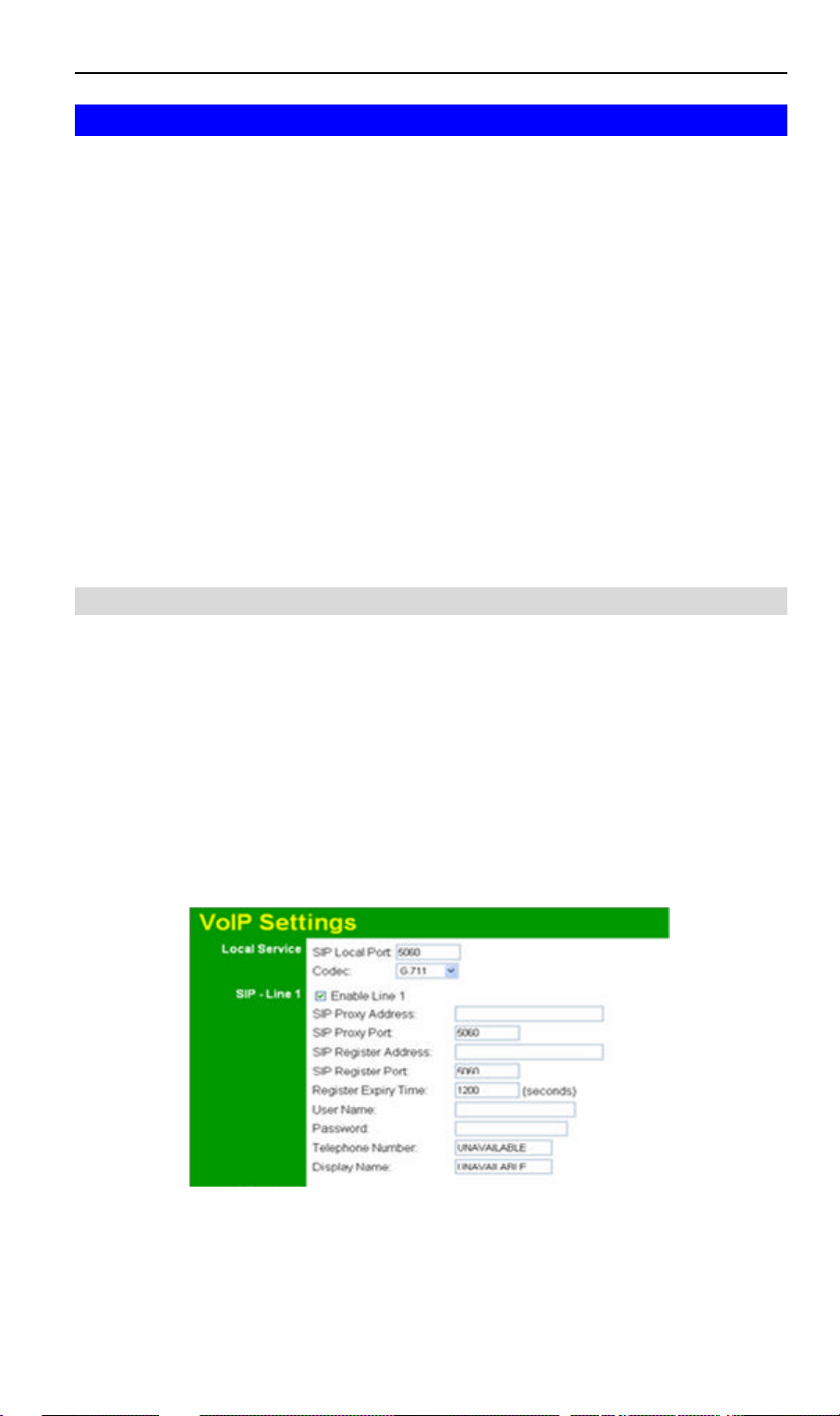
VoIP Setup Screen
The VoIP setup screen is not on the menu; the VoIP link on the menu displays the VoIP Status
screen, described later in this chapter.
To view the VoIP Setup Screen:
1. Connect to the 802.11g ADSL VoIP Gateway using its IP address and the path to the VoIP
Setup screen ( /set_voip.htm ). For example, if the default IP address has not been changed,
use the following:
http://192.168.0.1/set_voip.htm
2. You will see the VoIP Settings screen, like the example below. This screen allows input of
the data necessary to establish a connection to the SIP Server.
Note that the Line 2 settings are the same as Line 1; only Line 1 is shown below.
Figure 53: VoIP Settings
67
Page 12

802.11g ADSL VoIP Gateway User Guide
VoIP Settings
Local Service
SIP Local Port This port is used for peer -to-peer (direct) connections to another
device, when no SIP server is used.
Normally, this should be left at the default value. Any other devices
you wish to connect to must use the same port number.
SIP - Line 1 & Line 2
Enable Line1 Check this if you wish to connect to a SIP Server. If enabled, you
must provide the following data.
SIP Proxy ad dress Enter the address of the SIP Proxy (Server) used by your VoIP pr o-
vider.
SIP Proxy port Enter the port used for connections to the Server above.
SIP register ad-
dress
SIP register port Enter the port used for "Register" connections to the Server above.
Register
Expiry Time
User Name Enter the login name for connections to the SIP Server.
Password Enter the password associated with the login name above.
Telephone
Number
Display Name This name is used by the SIP Server, and may be visible to cal lers.
Enter the address of the SIP Register (Server) used by your VoIP
provider. This may be the same server as the "Proxy" above.
This sets the "Idle Timeout" for the SIP Server Login. An Idle connection will be terminated after this time period. Enter the desired value.
Enter the telephone number provided to you by the VoIP Service
provider. If you have a range of numbers, enter the number you wish
to use for this line.
68
Page 13
Advanced Features
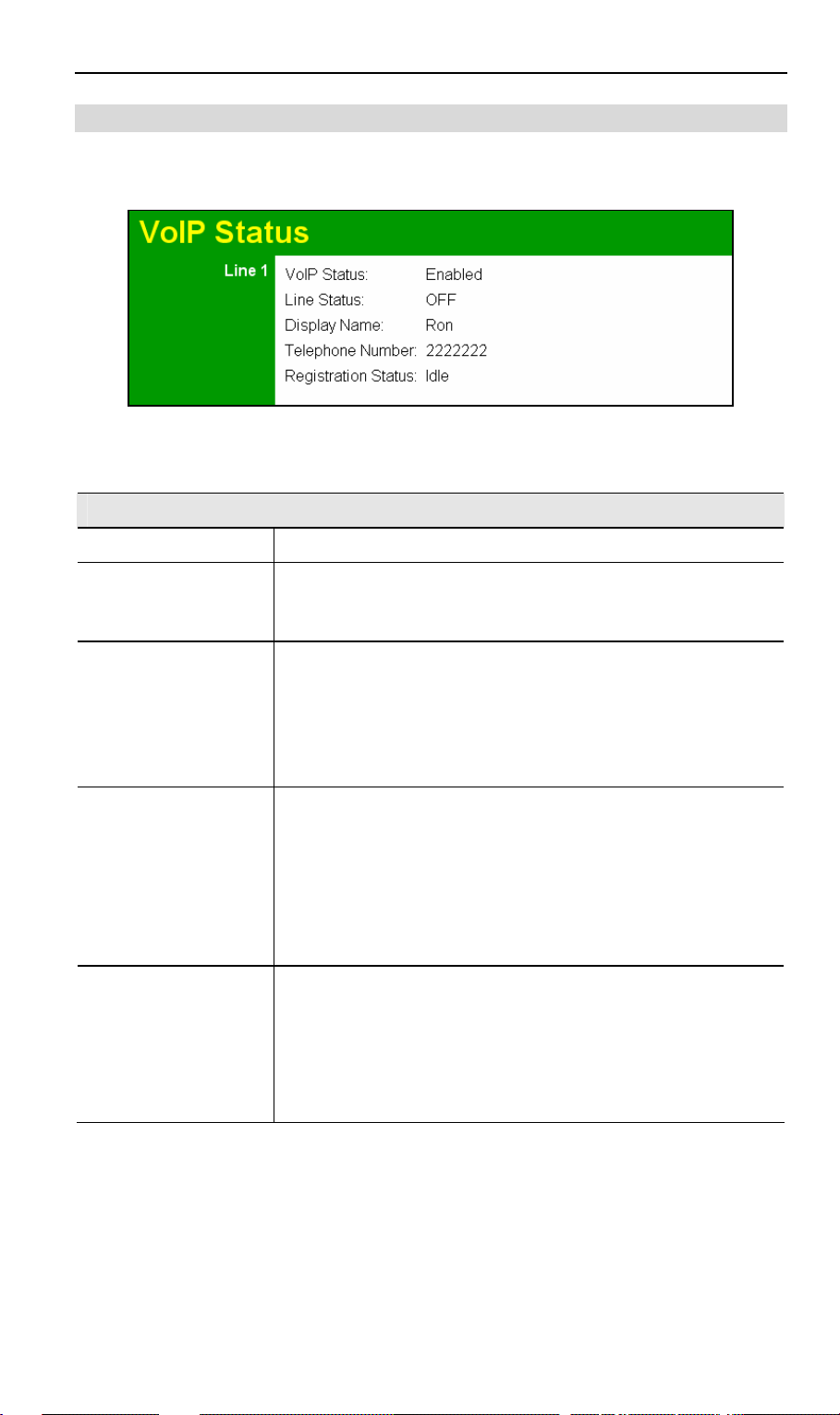
VoIP Status Screen
This screen allows you to check the status of the connection to the SIP Server. It is accessed
via the VoIP link on the Advanced menu. Status information for each line is shown.
Figure 54: VoIP Status Screen
VoIP Status
Line 1 & Line 2
VoIP Status This indicates if VoIP is enabled or disabled.
Line Status Sometimes called "Hook Status"; this indicates the status on the
telephone line. ON indicates the receiver is "on-the-hook", while
OFF indicates the receiver is "off-the-hook".
Display Name This is the name you chose when you first opened your account.
Your "Display Name" will be visible to other individuals with caller
ID.
If your display name appears as "UNAVAILABLE", either your
VoIP account has not been established or your router has been
unable to connect to the VoIP Server.
Telephone Number The telephone number associated with this line. This is the tel e-
phone number other people will use when they call you. This
number was assigned to you when you first established your
account. Each line can have a different telephone number.
If this displays "UNAVAILABLE", either your VoIP account has
not been established or this device was unable to connect to the
SIP server.
Registration Status This shows the status of the connection to the SIP Server. When
your router has successful ly connected, the status will be displayed as "Success".
However, if you do not have VoIP account or if the router could
not connect to the VoIP server, the status will be displayed as
"Idle".
69
Page 14
802.11g ADSL VoIP Gateway User Guide
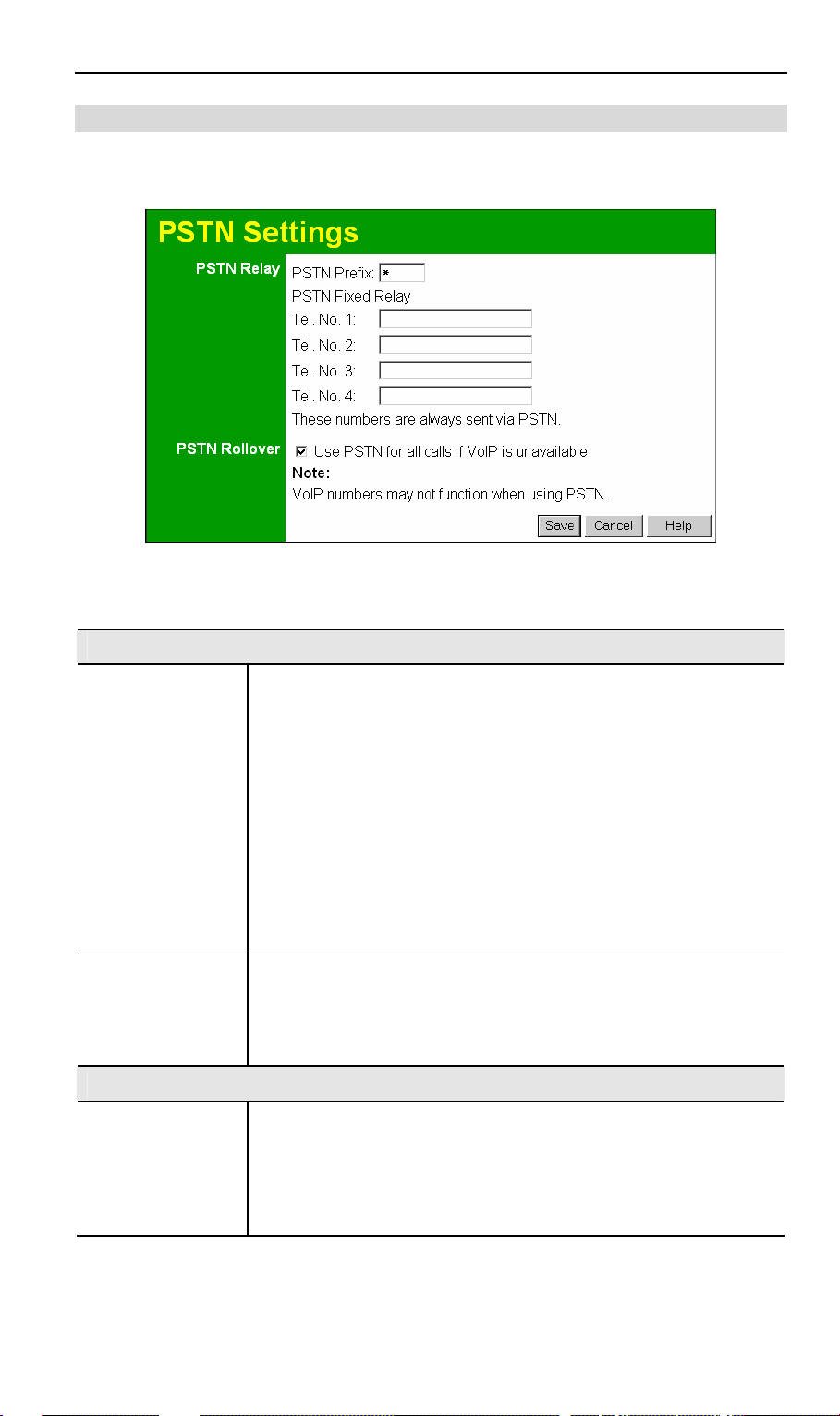
PSTN Settings Screen
This screen has some additional settings related to the use of the PSTN line, assuming the
PSTN line is connected, which is strongly recommended.
Figure 55: PSTN Screen
PSTN Settings
PSTN Relay
PSTN Prefix The PSTN Relay allow certain calls to be diverted to the PSTN link,
even though VoIP is working properly.
This PSTN prefix means that any number beginning with this prefix
will be diverted to PSTN (the prefix itself is deleted, then the remainder
of the number is dialed via PSTN).
• If the prefix is a single character, that character must be *
• If the prefix is multiple characters, all characters after the 1st
character must be digits. The 1st char character can be * or a digit.
Note: When dialing, do not wait for a 2nd dial tone for the PSTN; there
is no 2nd dial tone. Just dial the PSTN prefix and the desired phone
number.
PSTN Fixed Relay This provides another method of diverting calls to the PSTN link. Any
Telephone numbers listed in this table will always be dialed via PSTN.
This feature should be used to direct emergency numbers to the
PSTN.
PSTN Rollover
Use PSTN… If enabled, then when VoIP is unavailable, all calls from the handset
will be sent via PSTN. (This is the same effect as occurs when the
power is off.) However, note that VoIP phone numbers (beginning
with are often unreachable via PSTN.
Normally, this setting should be Enabled .
70
Page 15

6
Chapter 6
Advanced Administration
This Chapter explains the settings available via the "Administration" section
of the menu.
Overview
Normally, it is not necessary to use these screens, or change any settings. These screens and
settings are provided to deal with non-standard situations, or to provide additional options for
advanced users.
The available settings and features are:
PC Database This is the list of PCs shown when you select the "DMZ PC" or a
"Virtual Server". This database is maintained automatically, but
you can add and delete entries for PCs which use a Fixed (Static)
IP Address.
Config File Backup or restore the configuration file for the 802.11g ADSL VoIP
Gateway. This file contains all the configuration data.
Logging & Email View or clear all logs, set E -Mailing of log files and alerts.
Diagnostics Perform a Ping or DNS Lookup.
Remote Admin Allow settings to be changed from the Internet..
Routing Only required if your LAN has other Routers or Gateways.
Upgrade Firmware Upgrade the Firmware (software) installed in your 802.11g ADSL
VoIP Gateway.
71
Page 16

802.11g ADSL VoIP Gateway User Guide
PC Database
The PC Database is used whenever you need to select a PC (e.g. for the "DMZ" PC).
• It elim inates the need to enter IP addresses.
• Also, you do not need to use fixed IP addresses on your LAN.
However, if you do use a fixed IP address on some devices on your LAN, you should enter
details of each such device into the PC database, using the PC Database screen.
PC Database Screen
An example PC Database screen is shown below.
Figure 56: PC Database
• PCs which are "DHCP Clients" are automatically added to the database, and updated as
required.
• By default, non-Server versions of Window s act as "DHCP Clients"; this setting is called
"Obtain an IP Address automatically".
• The 802.11g ADSL VoIP Gateway uses the "Hardware Address" to identify each PC, not
the name or IP address. The "Hardware Address" can only change if you change the PC's
network card or adapter.
• This system means you do NOT need to use Fixed (static) IP addresses on your LAN.
However, you can add PCs using Fixed (static) IP Addresses to the PC database if required.
72
Page 17

PC Configuration
Data - PC Database Screen
Known PCs This lists all current entries. Data displayed is name (IP Address) type.
The "type" indicates whether the PC is connected to the LAN.
Name If adding a new PC to the list, enter its name here. It is best if this
matches the PC's "hostname".
IP Address Enter the IP Address of the PC. The PC will be sent a "ping" to deter-
mine its hardware address. If the PC is not available (not connected, or
not powered On) you will not be able to add it.
Buttons
Add This will add the new PC to the list. The PC will be sent a "ping" to
determine its hardware address. If the PC is not available (not connected, or not powered On) you will not be able to add it.
Delete Delete the selected PC from the list. This should be done in 2 situations:
• The PC has been removed from your LAN.
• The entry is incorrect.
Refresh Update the data on screen.
Generate Report Display a read-only list showing full details of all entries in the PC
database.
Advanced
Administration
View the Advanced version of the PC database screen - PC Database
(Admin). See below for details.
73
Page 18

802.11g ADSL VoIP Gateway User Guide
PC Database - Advanced
This screen is displayed if the "Advanced Administration" button on the PC Database is
clicked. It provides more control than the standard PC Database screen.
Figure 57: PC Database (Admin)
Data - Advanced PC Database
Known PCs This lists all current entries. Data displayed is name (IP Address) type.
The "type" indicates whether the PC is connected to the LAN.
PC Properties
Name If adding a new PC to the list, enter its name here. It is best if this
matches the PC's "hostname".
IP Address Select the appropriate option:
• Automatic - The PC is set to be a DHCP client (Windows: "O btain
an IP address automatically"). The 802.11g ADSL VoIP Gateway
will allocate an IP address to this PC when requested to do so. The
IP address could change, but normally won't.
• DCHP Client - Reserved IP Address - Select this if the PC is set to
be a DCHP client, and you wish to guarantee that the 802.11g
ADSL VoIP Gateway will always allocate the same IP Address to
this PC.
Enter the required IP address.
• Fixed IP Address - Select this if the PC is using a Fixed (Static) IP
address. Enter the IP address allocated to the PC. (The PC itself
must be configured to use this IP address.)
74
Page 19

PC Configuration
MAC Address Select the appropriate option
• Automatic discovery - Select this to have the 802.11g ADSL VoIP
Gateway contact the PC and find its MAC address. This is only
possible if the PC is connected to the LAN and powered On.
• MAC address is - Enter the MAC address on the PC. The MAC
address is also called the "Hardware Address", "Physical Address", or "Network Adapter Address". The 802.11g ADSL VoIP
Gateway uses this to provide a unique identifier for each PC. Because of this, the MAC address can NOT be left blank.
Buttons
Add as New Entry Add a new PC to the list, using the data in the "Properties" box.
If "Automatic discovery" (for MAC address) is selected, the PC will be
sent a "ping" to determine its hardware address. This will fail unless the
PC is connected to the LAN, and powered on.
Update Selected
Update (modify) the selected PC, using the data in the "Properties" box.
PC
Clear Form Clear the "Properties" box, ready for entering data for a new PC.
Refresh Update the data on screen.
Generate Report Display a read-only list showing full details of all entries in the PC
database.
Standard Screen Click this to view the standard PC Database screen.
75
Page 20

802.11g ADSL VoIP Gateway User Guide
Config File
This feature allows you to download the current settings from the 802.11g ADSL VoIP Gateway,
and save them to a file on your PC.
You can restore a previously-downloaded configuration file to the 802.11g ADSL VoIP Gateway,
by uploading it to the 802.11g ADSL VoIP Gateway.
This screen also allows you to set the 802.11g ADSL VoIP Gateway back to its factory default
configuration. Any existing settings will be deleted.
An example Config File screen is shown below.
Figure 58: Config File Screen
Data - Config File Screen
Backup Config Use this to download a copy of the current configuration, and stor e the
file on your PC. Click Download to start the download.
Restore Config This allows you to restore a previously-saved configuration file back to
the 802.11g ADSL VoIP Gateway.
Click Browse to select the configuration file, then click Restore to
upload the configuration file.
WARNING !
Uploading a configuration file will destroy (overwrite) ALL of the
existing settings.
Default Config Clicking the Factory Defaults button will reset the 802.11g ADSL VoIP
Gateway to its factory default settings.
WARNING !
This will delete ALL of the existing settings.
76
Page 21

PC Configuration
Logs
The Logs record various types of activity on the 802.11g ADSL VoIP Gateway. This data is
useful for troubleshooting, but enabling all logs will generate a large amount of data and adversely affect performance.
Since only a limited amount of log data can be stored in the 802.11g ADSL VoIP Gateway, log
data can also be E -mailed to your PC. Use the E-mail screen to configure this feature.
Figure 59: Logs Screen
Data - Logs Screen
Logs
Current Time The current time on the 802.11g ADSL VoIP Gateway is di splayed.
Log Data Current log data is displayed in this panel.
Buttons There are three (3) buttons
• Refresh - Update the log data.
• Clear Log - Clear the log, and restart it. This makes new
messages easier to read.
• Send Log - E -mail the log immediately. This is only functional
if the E-mail screen has been configured.
77
Page 22

802.11g ADSL VoIP Gateway User Guide
Logs
Include (Checkboxes) Use these checkboxes to determine which events are included in
the log. Checking all options will increase the size of the log, so it
is good practice to disable any events which are not really required.
• Attempted access to blocked sites - If checked, attempted
Internet accesses which were blocked are logged.
• Connections to the Web -based interface of this Router - If
checked, this will log connections TO this Router, rather than
through this Router to the Internet.
• Router operation - If checked, other Router operations (not
covered by the selections above) will be logged.
• Known DoS attacks and Port Scans - If checked, Denial of
Service attacks, as well as port scans, will be logged.
Syslog
Disable Data is not sent to a Syslog Server.
Broadcast on LAN The Syslog data is broadcast, rather than sent to a specific Syslog
server. Use this if your Syslog Server does not have a fixed IP
address.
Syslog If your Syslog server has a fixed IP address, select this option, and
enter the IP address of your Syslog server.
78
Page 23

PC Configuration
E-mail
This screen allows you to E -mail Logs and Alerts. A sample screen is shown below.
Figure 60: E -mail Screen
Data - E-mail Screen
E-Mail Notification
Turn E -mail Notification on
Send to this E -mail
address
Outgoing (SMTP)
Mail Server
My SMTP Mail
Server requires
authentication
User Name If you have enabled "My SMTP Mail Server requires authentication"
Password If you have enabled "My SMTP Mail Server requires authentication"
Check this box to enable this feature. If enabled, the E -mail address
information (below) must be provided.
Enter the E -mail address the Log is to be sent to. The E-mail will also
show this address as the Sender's address.
Enter the address or IP address of the SMTP (Simple Mail Transport
Protocol) Server you use for outgoing E -mail.
To stop spanners, many SMTP mail servers requi re you to log in to
send mail. In this case, enable this checkbox, and enter the login
information (User name and Password) in the fields below.
above, enter the User Name required to login to your SMTP Server.
above, enter the password required to login to your SMTP Server.
79
Page 24

802.11g ADSL VoIP Gateway User Guide
E-mail Alerts
Send E -mail alerts
immediately
You can choose to have alerts E -mailed to you, by checking the
desired checkboxes. The Broadband ADSL Router can send an
immediate alert when it detects a significant security incident such as
• A known hacker attack is directed at your IP address
• A computer on the Internet scans your IP address for open ports
• Someone on your LAN (Local Area Network) tries to visit a
blocked site.
E-mail Logs
Send Logs Select the desired option for sending the log by E -mail.
• Never (default) - This feature is disabled; Logs are not sent.
• When log is full - The time is not fixed. The log will be sent when
the log is full, which will depend on the volume of traffic.
• Hourly, Daily, Weekly... - The log is sent on the interval speci-
fied.
• If Daily is selected, the log is sent at the time specified.
Select the time of day you wish the E -mail to be sent.
• If Weekly is selected, the log is sent once per week, on the
specified day, at the specified time.
Select the day and the time of day you wish the E -mail to be
sent.
Note:
If the log is full before the time specified to send it, it will be sent
regardless of the day and time specified.
80
Page 25

PC Configuration
Diagnostics
This screen allows you to perform a "Ping" or a "DNS lookup". These activities can be useful in
solving network problems.
An example Network Diagnostics screen is shown below.
Figure 61: Network Diagnostics Screen
Data - Network Diagnostics Screen
Ping
Ping this
IP Ad dress
Ping Button After entering the IP address, click this button to start the "Ping"
DNS Lookup
Internet name Enter the Domain name or URL for which you want a DNS (Domain
Lookup Button After entering the Domain name/URL, click this button to start the
Routing
Display Click this button to display the internal routing table. This inform ation
Enter the IP address you wish to ping. The IP address can be on your
LAN, or on the Internet. Note that if the address is on the Internet,
and no connection currently exists, you could get a "Timeout" error.
In that case, wait a few seconds and try again.
procedure. The results will be displayed in the Ping Results pane.
Name Server) lookup. Note that if the address in on the Internet, and
no connection currently exists, you could get a "Timeout" error. In
that case, wait a few seconds and try again.
"DNS Lookup" procedure.
can be used by Technical Support and other staff who understand
Routing Tables.
81
Page 26

802.11g ADSL VoIP Gateway User Guide
Remote Administration
If enabled, this feature allows you to manage the 802.11g ADSL VoIP Gateway via the Internet.
Figure 62: Remote Administration Screen
Data - Remote Administration Screen
Remote Administration
Enable Remote
Management
Current
IP Ad dress
Port Number Enter a port number between 1 and 65535. The default for HTTP
Access Permission
Allow Remote
Access
Check to allow administration/management via the Internet. (To
connect, see below).
If Disabled, this device will ignore Administration connection attempts from the Internet.
This is the current address you will use when accessing this device
from the Internet. To connect, see details and an example below.
(Web) connections is port 80, but using port 80 will prevent the use of
a Web "Virtual Server" on your LAN. So using a different port number is recommended. The default value is 8080.
The port number must be specified in your Browser when you connect. See the following section for details.
Select the desired option.
• Everyone - allow access by everyone on the Internet.
• Only This Computer - allow access by only one IP address. Enter
the desired IP address.
• IP Address Range - allow access from a range of IP addresses on
the Internet. Enter a beginning and ending IP address to define
the allowed range.
For security, you should restrict access to as few external IP addresses as practical.
82
Page 27

PC Configuration
To connect from a remote PC via the Internet
1. Ensure your Internet connection is established, and start your Web Browser.
2. In the "Address" bar, enter "HTTP://" followed by the Internet IP Address of the 802.11g
ADSL VoIP Gateway. If the port number is not 80, the port number is also required. (After
the IP Address, enter ":" followed by the port number.)
e.g.
HTTP://123.123.123.123:8080
This example assumes the WAN IP Address is 123.123.123.123, and the port number is 8080.
3. You will then be prompted for the login name and password for this device.
83
Page 28

802.11g ADSL VoIP Gateway User Guide
Routing
Overview
• If you don't have other Routers or Gateways on your LAN, you can ignore the "Routing"
page completely.
• If the 802.11g ADSL VoIP Gateway is only acting as a Gateway for the local LAN segment,
ignore the "Routing" page even if your LAN has other Routers.
• If your LAN has a standard Router (e.g. Cisco) on your LAN, and the 802.11g ADSL VoIP
Gateway is to act as a Gateway for all LAN segments, enable RIP (Routing Inform ation Protocol) and ignore the Static Routing table.
• If your LAN has other Gateways and Routers, and you wish to control which LAN seg-
ments use each Gateway, do NOT enable RIP (Routing Information Protocol). Configure the
Static Routing table instead. (You also need to configure the other Routers.)
• If using Windows 2000 Data center Server as a software Router, enable RIP on the 802.11g
ADSL VoIP Gateway, and ensure the following Windows 2000 settings are correct:
• Open Routing and Remote Access
• In the console tree, select Routing and Remote Access , [server name], IP Routing,
RIP
• In the "Details" pane, right-click the interface you want to configure for RIP version 2,
and then click "Properties".
• On the "General" tab, set Outgoing packet protocol to "RIP version 2 broadcast", and
Incoming packet protocol to "RIP version 1 and 2".
Routing Screen
The routing table is accessed by the Routing link on the Administration menu.
Using this Screen
Generally, you will use either RIP (Routing Information Protocol) OR the Static Routing Table,
as explained above, although is it possible to use both methods simultaneously.
Static Routing Table
• If RIP is not used, an entry in the routing table is required for each LAN segment on your
Network, other than the segment to which this device is attached.
• The other Routers must also be configured. See Configuring Other Routers on your LAN
later in this chapter for further details and an example.
84
Page 29

PC Configuration
Data - Routing Screen
Figure 63: Routing Screen
RIP
RIP Direction Select the desired RIP Direction.
RIP Version Choose the RIP Version for the Server.
Static Routing
Static Routing
Table Entries
Buttons
Add Add a new entry to the Static Routing table, using the data shown in
Edit Update the current Static Routing Table entry, using the data shown
Delete Delete the current Static Routing Table entry.
Save Save the RIP setting. This has no effect on the Static Routing Table.
This list shows all entries in the Routing Table.
• This area shows details of the selected item in the list.
• Change any the properties as required, then click the "Edit"
button to save the changes to the selected entry.
the "Properties" area on screen. The entry selected in the list is
ignored, and has no effect.
in the table area on screen.
Configuring Other Routers on your LAN
It is essential that all IP packets for devices not on the local LAN be passed to the 802.11g
ADSL VoIP Gateway, so that they can be forwarded to the external LAN, WAN, or Internet. To
achieve this, the local LAN must be configured to use the 802.11g ADSL VoIP Gateway as the
Default Route or Default Gateway.
85
Page 30

802.11g ADSL VoIP Gateway User Guide
Local Router
The local router is the Router installed on the same LAN segment as the 802.11g ADSL VoIP
Gateway. This router requires that the Default Route is the 802.11g ADSL VoIP Gateway itself.
Typically, routers have a special entry for the Default Route. It should be configured as follows.
Destination IP Address Normally 0.0.0.0, but check your router documentation.
Network Mask Normally 0.0.0.0, but check your router documentation.
Gateway IP Address The IP Address of the 802.11g ADSL VoIP Gateway.
Metric 1
Other Routers on the Local LAN
Other routers on the local LAN must use the 802.11g ADSL VoIP Gateway's Local Router as the
Default Route. The entries will be the same as the 802.11g ADSL VoIP Gateway's local router,
with the exception of the Gateway IP Address.
• For a router with a direct connection to the 802.11g ADSL VoIP Gateway's local Router, the
Gateway IP Address is the address of the 802.11g ADSL VoIP Gateway's local router.
• For routers which must forward packets to another router before reaching the 802.11g
ADSL VoIP Gateway's local router, the Gateway IP Address is the address of the interm ediate router.
Static Routing - Example
Figure 64: Routing Example
For the 802.11g ADSL VoIP Gateway's Routing Table
For the LAN shown above, with 2 routers and 3 LAN segments, the 802.11g ADSL VoIP
Gateway requires 2 entries as follows.
Entry 1 (Segment 1)
Destination IP Address 192.168.1.0
Network Mask 255.255.255.0 (Standard Class C)
86
Page 31

PC Configuration
Gateway IP Address 192.168.0.100 (802.11g ADSL VoIP Gateway's
Metric 2
Entry 2 (Segment 2)
Destination IP Address 192.168.2.0
Network Mask 255.255.255.0 (Standard Class C)
Gateway IP Address 192.168.0.100
Metric 3
For Router A's Default Route
Destination IP Address 0.0.0.0
Network Mask 0.0.0.0
Gateway IP Address 192.168.0.1 (802.11g ADSL VoIP Gateway's IP
For Router B's Default Route
Destination IP Address 0.0.0.0
local Router)
Address)
Network Mask 0.0.0.0
Gateway IP Address 192.168.1.80 (802.11g ADSL VoIP Gateway's
local router)
87
Page 32

802.11g ADSL VoIP Gateway User Guide
Upgrade Firmware
The firmware (software) in the 802.11g ADSL VoIP Gateway can be upgraded using your Web
Browser.
You must first download the upgrade file, then select Upgrade Firmware on the Administration
menu. You will see a screen like the following.
Figure 65: Router Upgrade Screen
To perform the Firmware Upgrade:
1. Click the Browse button and navigate to the location of the upgrade file.
2. Select the upgrade file. Its name will appear in the Upgrade File field.
3. Click the Upload button to commence the firmware upgrade.
The 802.11g ADSL VoIP Gateway is unavailable during
the upgrade process, and must restart when the upgrade
is completed. Any connections to or through the 802.11g
ADSL VoIP Gateway will be lost.
88
Page 33

7
Chapter 7
Operation and Status
This Chapter details the operation of the 802.11g ADSL VoIP Gateway and
the status screens.
Operation
Once both the 802.11g ADSL VoIP Gateway and the PCs are configured, operation is automatic.
However, there are some situations where additional Internet configuration may be required.
Refer to Chapter 5 - Advanced Features for further details.
Status Screen
Use the Status link on the main m enu to view this screen.
Figure 66: Status Screen
89
Page 34

802.11g ADSL VoIP Gateway User Guide
Data - Status Screen
System
Device Name The current name of the Router. This name is also the "hostname"
for users with an "@Home" type connection.
Firmware Version The version of the current firmware installed.
ADSL
Modem Status This indicates the status of the ADSL modem component.
DownStream
Connection Speed
UpStream Connection
Speed
VC 1 Status The current VCI setting.
VPI The current VPI setting.
ADSL
Details
Internet (VC1)
Connection Method Displays the current connection method, as set in the Setup
Connection Status This indicates the current status of the Internet Connection
Displays the speed for the DownStream Connection.
If connected, displays the speed for the Up Stream (upload) ADSL
Connection.
Click this button to open a sub-window and view the details of
each VC (Virtual Circuit).
Wizard.
• Active - Connection exists
• Idle - No current connection, but no error has been detected.
This condition normally arises when an idle connection is
automatically terminated.
• Failed - The connection was terminated abnormally. This
could be caused by Modem failure, or the loss of the connection to the ISP's server.
If there is an error, you can click the "Connection Details" button
to find out more information.
Internet IP Address This IP Address is allocated by the ISP (Internet Service Provider).
If using a dynamic IP address, and no connection currently exists,
this information is unavailable.
Connection Details Click this button to open a sub-window and view a detailed
description of the current connection. Depending on the type of
connection, a "log" may also be available.
LAN
IP Address The IP Address of the 802.11g ADSL VoIP Gateway.
Network Mask The Network Mask (Subnet Mask) for the IP Address above.
DHCP Server This shows the status of the DHCP Server function. The value will
be "Enabled" or "Disabled".
MAC Address This shows the MAC Address for the 802.11g ADSL VoIP Gate-
way, as seen on the LAN interface.
90
Page 35

Advanced Administration
Wireless
Name (SSID) If using an ESS (Extended Service Set, with multiple access points)
this ID is called an ESSID (Extended Service Set Identifier).
Region The current region, as set on the Wireless screen.
Channel This shows the Channel currently used, as set on the Wireless
screen.
Wireless AP This indicates whether or not the Wireless Access Point feature is
enabled.
Broadcast Name This indicates whether or not the SSID is Broadcast. This setting
is on the Wireless screen.
Buttons
ADSL Details View the details of each VC (Virtual Circuit).
Connection Details Click this button to open a sub-window and view a detai led
description of the current connection.
Attached Devices This will open a sub-window, showing all LAN and Wireless
devices currently on the network.
Refresh Screen Update the data displayed on screen.
91
Page 36

802.11g ADSL VoIP Gateway User Guide
Connection Status - PPPoE & PPPoA
If using PPPoE (PPP over Ethernet) or PPPoA (PPP over ATM), a scren like the following
example will be di splayed when the "Connection Details" button is clicked.
Figure 67: PPPoE Status Screen
Data - PPPoE/PPPoA Screen
Connection Time This indicates how long the current connection has been estab-
lished.
PPPoE Link Status This indicates whether or not the connection is currently estab-
lished.
• If the connection does not exist, the "Connect" button can be
used to establish a connection.
• If the connection currently exists, the "Disconnect" button
can be used to break the connection.
Negotiation This indicates the status of the PPPoE Server login.
IP Address The IP Address of this device, as seen by Internet users. This
address is allocated by your ISP (Internet Service Provider).
Network Mask The Network Mask associated with the IP Address above.
Buttons
Connect If not connected, establish a connection to your ISP.
Disconnect If connected to your ISP, hang up the connection.
Close Close this window.
92
Page 37

Advanced Administration
Connection Details - Dynamic IP Address
If your access method is "Direct" (no login), with a Dynamic IP address, a screen like the
following example will be displayed when the "Connection Details" button is clicked.
Figure 68: Connection Details - Fixed/Dynamic IP Address
Data - Dynamic IP address
Internet
IP Address The current IP Address of this device, as seen by Internet users. This
address is allocated by your ISP (Internet Service Provider).
Network Mask The Network Mask associated with the IP Address above.
Default Gateway The IP address of the remote Gateway or Router associated with the
IP Address above.
DHCP Server The IP address of your ISP's DHCP Server.
DNS Server The IP address of the Domain Name Server which is currently used.
Lease Obtained
Lease Expires
Buttons
Release If an IP Address has been allocated to the 802.11g AD SL VoIP Gate-
Renew If the ISP's DHCP Server has NOT allocated an IP Address for the
This indicates when the current IP address was obtained, and how
long before this IP address allocation (the DCHP lease) expires.
way (by the ISP's DHCP Server, clicking the "Release" button will
break the connection and release the IP Address.
802.11g ADSL VoIP Gateway, clicking the "Renew" button will attempt to re-establish the connection and obtain an IP Address from
the ISP's DHCP Server.
Close Close this window.
93
Page 38

802.11g ADSL VoIP Gateway User Guide
Connection Details - Fixed IP Address
If your access method is "Direct" (no login), with a fixed IP address, a screen like the following
example will be displayed when the "Connection Details" button is clicked.
Figure 69: Connection Details - Fixed/Dynamic IP Address
Data - Fixed IP address Screen
Internet
IP Address The IP Address of this device, as seen by Internet users. This ad-
dress is allocated by your ISP (Internet Service Provider).
Network Mask The Network Mask associated with the IP Address above.
Default Gateway The IP Address of the remote Gateway or Router associated with the
IP Address above.
DNS Server The IP Address of the Domain Name Server which is currently used.
94
Page 39

Advanced Administration
Using VoIP
VoIP cannot be used until configuration has been completed. See the VoIP topic in Chapter 5 Advanced Features for details of VoIP configuration.
Normal Operation
• Y our Internet connection should be configured to keep the Internet connection active as
much as possible (Keep Alive).
• Once logged in to the SIP server, you can dial any number using the procedure specified
by your VoIP Service provider.
• You can dial any number via the PSTN (provided the PSTN line is connected) by first
dialing the PSTN Prefix specified on the PSTN screen.
Note: Do not wait for a 2nd dial tone for the PSTN; there is no 2nd dial tone.
Just dial the PSTN prefix and the desired tel ephone number.
• If there is no Internet connection, you can still use the phone provided the PSTN setting
Use PSTN for all calls if VoIP is unavailable is Enabled . (This setting is on the PSTN
screen.) In this case, the call will go via PSTN and you will be charged accordingly by your
telephone company.
• If there is no power, you can still use the phone provided the PSTN line is connected. In
this case, the call will go via PSTN and you will be charged accordingly by your telephone
company.
Advanced Call Features
The 802.11g ADSL VoIP Gateway supports Call Waiting and 3-Way Conference calls.
Note: The instruction below refer to the "flash hook" button. This may be labeled "Recall" on
your phone. If you phone does not have a "flash hook" button, you can instead briefly press
the button or pad used to hang up the phone.
Call Waiting
Call waiting alerts you to another incoming call when you are already having a telephone
conversation, and allows you to answer the incoming call:
• Your phone will ring.
• Press "flash hook" to answer the incoming call. The other caller will be placed on hold.
• Press "flash hook" to swap between the two calls.
If you hang up when finished speaking to one caller, your phone will ring if the other caller is
still on-line.
Note: You can disable the Call Waiting feature by dialing *70
You will hear the dial tone and can dial the required number. This ensures the call will not be
interrupted by an incoming call.
3-Way Conference Calls
This feature allows you to speak to 2 other people simultaneously. To use this feature:
• Establish the first call.
• Press "flash hook"
• Dial the 2nd person
95
Page 40

A
Appendix A
Troubleshooting
This Appendix covers the most likely problems and their solutions.
Overview
This section covers some common problems that may be encountered while using the 802.11g
ADSL VoIP Gateway and some possible solutions to them. If you follow the suggested steps
and the 802.11g ADSL VoIP Gateway still does not function properly, contact your dealer for
further advice.
General Problems
Problem 1: Can't connect to the 802.11g ADSL VoIP Gateway to configure it.
Solution 1: Check the following:
• The 802.11g ADSL VoIP Gateway is properly installed, LAN connections
are OK, and it is powered ON.
• Ensure that your PC and the 802.11g ADSL VoIP Gateway are on the
same network segment. (If you don't have a router, this must be the
case.)
• If your PC is set to "Obtain an IP Address automatically" (DHCP client),
restart it.
• If your PC uses a Fixed (Static) IP address, ensure that it is using an IP
Address within the range 192.168.0.2 to 192.168.0.254 and thus com patible with the 802.11g ADSL VoIP Gateway's default IP Address of
192.168.0.1.
Also, the Network Mask should be set to 255.255.255.0 to match the
802.11g ADSL VoIP Gateway.
In Windows, you can check these setti ngs by using Control Panel-
Network to check the Properties for the TCP/IP protocol.
Internet Access
Problem 1: When I enter a URL or IP address I get a time out error.
Solution 1: A number of things could be causing this. Try the following troubleshooting
steps.
• Check if other PCs work. If they do, ensure that your PCs IP settings are
correct. If using a Fixed (Static) IP Address, check the Network Mask,
Default gateway and DNS as well as the IP Address.
• If the PCs are configured correctly, but still not working, check the
802.11g ADSL VoIP Gateway. Ensure that it is connected and ON. Connect to it and check its settings. (If you can't connect to it, check the
LAN and power connections.)
• Check the 802.11g ADSL VoIP Gateway's status screen to see if it is
96
Page 41

Appendix A - Troubleshooting
working correctly.
Problem 2: Some applications do not run properly when using the 802.11g ADSL VoIP
Gateway.
Solution 2: The 802.11g ADSL VoIP Gateway processes the data passing through it, so it
is not transparent.
For incoming connections, you must use the Virtual Server or Firewall Rules
to specify the PC which will receive the incoming traffic.
You can also use the DMZ function. This should work with almost every
application, but:
• It is a security risk, since the firewall is disabled.
• Only one (1) PC can use this feature.
Wireless Access
Problem 1: My PC can't locate the Wireless Access Point.
Solution 1: Check the following.
• Your PC is set to Infrastructure Mode. (Access Points are always in
Infrastructure Mode)
• The SSID on your PC and the Wirel ess Access Point are the same.
Remember that the SSID is case -sensitive. So, for example "Workgroup"
does NOT match "workgroup".
• Both your PC and the 802.11g ADSL VoIP Gateway must have the same
setting for WEP. The default setting for the 802.11g ADSL VoI P Gateway
is disabled, so your wireless station should also have WEP disabled.
• If WEP is enabled on the 802.11g ADSL VoIP Gateway, your PC must
have WEP enabled, and the key must match.
• If the 802.11g ADSL VoIP Gateway's Wireless screen is set to Allow
Trusted PCs only, then each of your Wireless stations must have been
designated as "Trusted", or the Wireless station will be blocked.
• To see if radio interference is causing a problem, see if connection is
possible when close to the 802.11g ADSL VoIP Gateway.
Remember that the connection range can be as little as 100 feet in poor
environments.
Problem 2: Wireless connection speed is very slow.
Solution 2: The wireless system will connect at the highest possible speed, depending
on the distance and the environment. To obtain the highest possible connection speed, you can experiment with the following:
• 802.11g ADSL VoIP Gateway location.
Try adjusting the location and orientation of the 802.11g ADSL VoIP
Gateway.
• Wireless Channel
If interference is the problem, changing to another channel may show a
marked improvement.
• Radio Interference
Other devices may be causing interference. You can experiment by
switching other devices Off, and see if this helps. Any "noisy" devices
should be shielded or relocated.
97
Page 42

802.11g ADSL VoIP Gateway User Guide
• RF Shielding
Your environment may tend to block transmission between the wireless
stations. This will mean high access speed is only possible when close
to the 802.11g ADSL VoIP Gateway.
98
Page 43

B
Appendix B
About Wireless LANs
This Appendix provides some background information about using Wireless
LANs (WLANs).
Modes
Wireless LANs can work in either of two (2) modes:
• Ad-hoc
• Infrastructure
Ad-hoc Mode
Ad-hoc mode does not require an Access Point or a wired (Ethernet) LAN. Wireless Stations (e.g. notebook PCs with wireless cards) communicate directly with each other.
Infrastructure Mode
In Infrastructure Mode, one or more Access Points are used to connect Wireless Stations
(e.g. Notebook PCs with wireless cards) to a wired (Ethernet) LAN. The Wireless Stations
can then access all LAN resources.
Access Points can only function in "Infrastructure" mode, and
can communicate only with Wireless Stations which are set
to "Infrastructure" mode.
BSS/ESS
BSS
A group of Wireless Stations and a single Access Point, all using the same ID (SSID), form a
Basic Service Set (BSS).
Using the same SSID is essential. Devices with different SSIDs are unable to communicate with
each other.
ESS
A group of Wireless Stations, and multiple Access Points, all using the same ID (ESSID), form
an Extended Service Set (ESS).
Different Access Points within an ESS can use different Channels. In fact, to reduce interference,
it is recommended that adjacent Access Points SHOULD use different channels.
As Wireless Stations are physically moved through the area covered by an ESS, they will
automatically change to the Access Point which has the least interference or best performance.
This capability is called Roaming. (Access Points do not have or require Roaming capabilities.)
99
Page 44

802.11g ADSL VoIP Gateway User Guide
Channels
The Wireless Channel sets the radio frequency used for communication.
• Access Points use a fixed Channel. You can select the Channel used. This allows you to
choose a Channel which provides the least interference and best performance. In the USA
and Canada, 11 channel are available. If using multiple Access Points, it is better if adj acent
Access Points use different Channels to reduce interference.
• In "Infrastructure" mode, Wireless Stations normally scan all Channels, looking for an
Access Point. If more than one Access Point can be used, the one with the strongest signal
is used. (This can only happen within an ESS.)
• If using "Ad-hoc" mode (no Access Point), all Wireless stations should be set to use the
same Channel. However, most Wireless stations will still scan all Channels to see if there is
an existing "Ad-hoc" group they can join.
WEP
WEP (Wired Equivalent Privacy) is a standard for encrypting data before it is transmitted.
This is desirable because it is impossible to prevent snoopers from receiving any data which is
transmitted by your Wireless Stations. But if the data is encrypted, then it is meaningless
unless the receiver can decrypt it.
If WEP is used, the Wireless Stations and the Access Point must have the same settings for
each of the following:
WEP Off, 64 Bit, 128 Bit
Key For 64 Bit encryption, the Key value must match.
For 128 Bit encryption, the Key value must match
WEP Authentication Open System or Shared Key.
WPA-PSK
WPA-PSK is another standard for encrypting data before it is transmitted. This is a later standard than WEP (Wired Equivalent Privacy), and provides greater security for your data. Data is
encrypted using a 256Bit key which is automatically generated and changed often.
If all your Wireless stations support WPA-PSK, you should use this instead of WEP.
If WPA-PSK is used, the Wireless Stations and the Access Point must have the same se ttings
for each of the following:
WPA PSK
(Pre-shared Key)
Enter the same value on every station and the AP. The PSK
must be from 8 to 63 characters in length. The 256Bit key
used for the actual encryption is derived from this key.
Encryption The same encryption method must be used. The most
common encryption method is TKIP. Another widelysupported method is AES.
100
Page 45

Appendix B - About Wireless LANs
Wireless LAN Configuration
To allow Wireless Stations to use the Access Point, the Wireless Stations and the Access Point
must use the same settings, as follows:
Mode On client Wireless Stations, the mode must be set to "Infrastructure".
(The Access Point is always in "Infrastructure" mode.)
SSID (ESSID) Wireless Stations should use the same SSID (ESSID) as the Access
Point they wish to connect to. Alternatively, the SSID can be set to
"any" or null (blank) to allow connection to any Access Point.
Wireless
Security
The Wireless Stations and the Access Point must use the same settings
for Wireless security. (None, WEP, WPA-PSK).
WEP: If WEP is used, the Key size (64Bit, 128Bit), Key value, and
Authentication settings must be the same on the Wireless Stations and
the Access Point.
WPA-PSK: If WPA-PSK is used, all Wireless Stations must be set to
use WPA-PSK, and have the same Pre-shared Key and encryption
system.
For Ad -hoc networks (no Access Point), all Wireless stations must use
the same security settings.
101
Page 46

C
Appendix C
Specifications
802.11g ADSL VoIP Gateway
Model 802.11g ADSL VoIP Gateway
Dimensions 183mm(W) * 125mm(D) * 31mm(H)
Operating Temper ature 0° C to 40° C
Storage Temperature -10° C to 70° C
Network Protocol: TCP/IP
ADSL Interface 1 * RJ11 connector
T1.413, G.DMT, G.lite, multi -mode
Ethernet Interface:
Phone Line Interface 1 * RJ11 connector for PSTN Phone Line
LEDs 16
Power Adapter 15 V DC External
1 * 10/100BaseT (RJ45) LAN port
2 * RJ11 connector for standard analog telephone
Wireless Interface
Standards IEEE802.11b, IEEE802.11g WLAN
Frequency 2.4 to 2.4835GHz (Industrial Scientific Medical Band )
Channels Maximum 14 Channels, depending on regulatory author ities
Modulation CCK, DQPSK, DBPSK, OFDM/CCK
Data Rate Up to 54 Mbps (802.11g)
Security WEP 64Bit, WPA 128Bit, WPA-PSK, MAC address checking
Output Power 13dBm (typical)
Receiver Sensiti vity -80dBm Min.
102
Page 47

Regulatory Approvals
FCC Statement
This equipment has been tested and found to comply with the limits for a Class B digital
device, pursuant to Part 15 of the FCC Rules. These limits are designed to provide reasonable
protection against harmful interference in a residential installation.
This equipment generates, uses and can radiate radio frequency energy and, if not installed and
used in accordance with the instructions, may cause harmful interference to radio communications. However, there is no guarantee that interference will not occur in a particular installation.
If this equipment does cause harmful interference to radio or television reception, which can be
determined by turning the equipment off and on, the user is encouraged to try to correct the
interference by one of the following measures:
Reorient or relocate the receiving antenna.
Increase the separation between the equipment and receiver.
Connect the equipment into an outlet on a circuit different from that to which the receiver
is connected.
Consult the dealer or an experienced radio/TV technician for help.
To assure continued compliance, any changes or modifications not expressly approved by the
party responsible for compliance could void the user's authority to operate this equipment.
(Example - use only shielded interface cables when connecting to computer or peripheral
devices).
FCC Radiation Exposure Statement
This equipment complies with FCC RF radiation exposure limits set forth for an uncontrolled
environment. This equipment should be installed and operated with a minimum distance of 20
centimeters between the radiator and your body.
This device complies with Part 15 of the FCC Rules. Operation is subject to the following two
conditions:
(1) This device may not cause harmful interference, and
(2) This device must accept any interference received, including interference that may cause
undesired operation.
This transmitter must not be co-located or operating in conjunction with any other antenna or
transmitter.
The antennas used for this transmitter must be installed to provide a separation distance of at
least 20 cm from all persons and must not be co-located or operating in conjunction with any
other antenna or transmitter.
Channel
The Wireless Channel sets the radio frequency used for communication.
•Access Points use a fixed Channel. You can select the Channel used. This allows you to
choose a Channel which provides the least interference and best performance. In the USA
and Canada, 11 channel are available. If using multiple Access Points, it is better if adjacent
Access Points use different Channels to reduce interference.
• In "Infrastructure" mode, Wireless Stations normally scan all Channels, looking for an
Access Point. If more than one Access Point can be used, the one with the strongest
signal is used. (This can only happen within an ESS.)
• If using "Ad-hoc" mode (no Access Point), all Wireless stations should be set to use the
same Channel. However, most Wireless stations will still scan all Channels to see if there
is an existing "Ad-hoc" group they can join.
CAUTION:
1) To comply with FCC RF exposure compliance requirements, a separation
distance of at least 20 cm must be maintained between the antenna of this
device and all persons.
2) This transmitter must not be co-located or operating in conjunction with
any other antenna or transmitter.
 Loading...