

Page 1
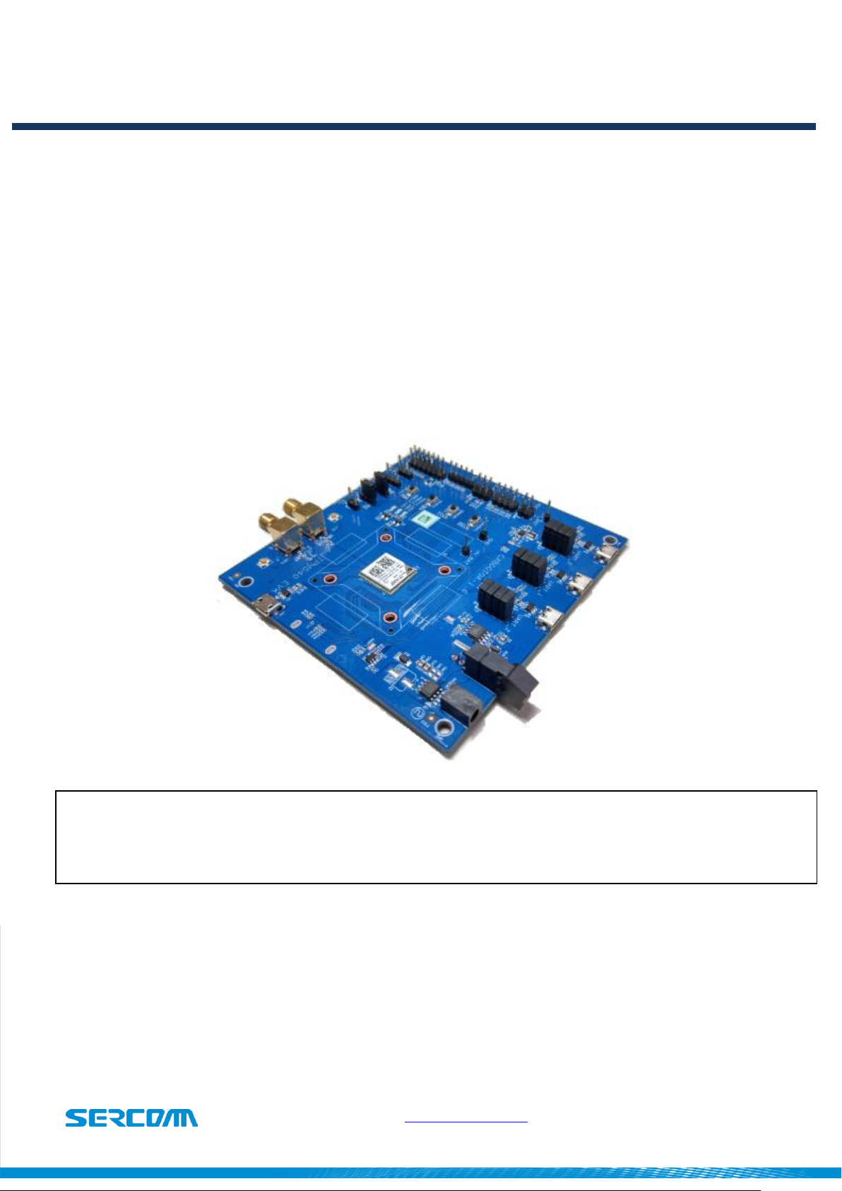
TPM540 EVK
Cat-M1/NB1 Module
Ver 1.0
TPM540 EVK
USER GUIDE
Specifications are subject to change without notice and should not be
construed as a commitment by Sercomm Corporation
Copyright 2017 by Sercomm Corporation All rights reserved.
www.sercomm.com DOC- 1
Page 2

TPM540 EVK
Cat-M1/NB1 Module
Revision History
Rev
Date
Description
V1.0
04/11/2017
Initial Release V1.0
Document Revision History
www.sercomm.com DOC-669671v1 2
Page 3

TPM540 EVK
Cat-M1/NB1 Module
Table of contents
1. Introduction ........................................................................................................................................................................ 4
1.1. Document Purpose .............................................................................................................................................. 4
1.2. Kit contents ........................................................................................................................................................ 4
2. EVK functions introduce ........................................................................................................................................................ 5
2.1. EVK Block Diagram .............................................................................................................................................. 5
2.2. EVK Interfaces ..................................................................................................................................................... 6
3. Starting with TPM540 EVK ..................................................................................................................................................... 7
3.1. Hardware preparation and setup .......................................................................................................................... 7
3.2. Software preparation and setup ............................................................................................................................ 8
3.3. Starting to access EVK and TPM540 ....................................................................................................................... 8
4. Button introduce .................................................................................................................................................................. 9
4.1. RECOVERY button:............................................................................................................................................... 9
4.2. WAKEUP button: ................................................................................................................................................. 9
4.3. RESET button: ..................................................................................................................................................... 9
4.4. STATUS button: ................................................................................................................................................... 9
5. LED status ..........................................................................................................................................................................10
5.1. Module_PWR1 LED: ............................................................................................................................................10
5.2. Module_LED1: ...................................................................................................................................................10
5.3. Module_LED2: ...................................................................................................................................................10
6. Special hardware configuration pins ......................................................................................................................................11
6.1. SWD(JP17): TBD .................................................................................................................................................11
6.2. Isolation control(JP3): .........................................................................................................................................11
6.3. Debug Selection(JP12): .......................................................................................................................................11
6.4. Anti Tamper(JP11): TBD ......................................................................................................................................11
7. Firmware Upgrade ...............................................................................................................................................................12
www.sercomm.com DOC-669671v1 3
Page 4

TPM540 EVK
Cat-M1/NB1 Module
1. Introduction
1.1. Document Purpose
The purpose of this document is to introduce TPM540 EVK and to provide a design reference.
EVK also enables users to make a prototype on TPM540 platform which resembles the actual
target during the design and build phases of a project. It makes the design efforts of a user
simple, cost-effective and fast. Various interfaces which is included on the board make the
development board ideal for a wide variety of applications. The EVK leverages the capability of
the TPM540 LTE Cat. M1 cellular module and provides access to a variety of interfaces including
UART, USB, USIM.
1.2. Kit contents
Three USB to Micro USB Cables
TPM540 EVK
One SMA-type Antenna
www.sercomm.com DOC-669671v1 4
Page 5
TPM540 EVK
Cat-M1/NB1 Module
2. EVK functions introduce
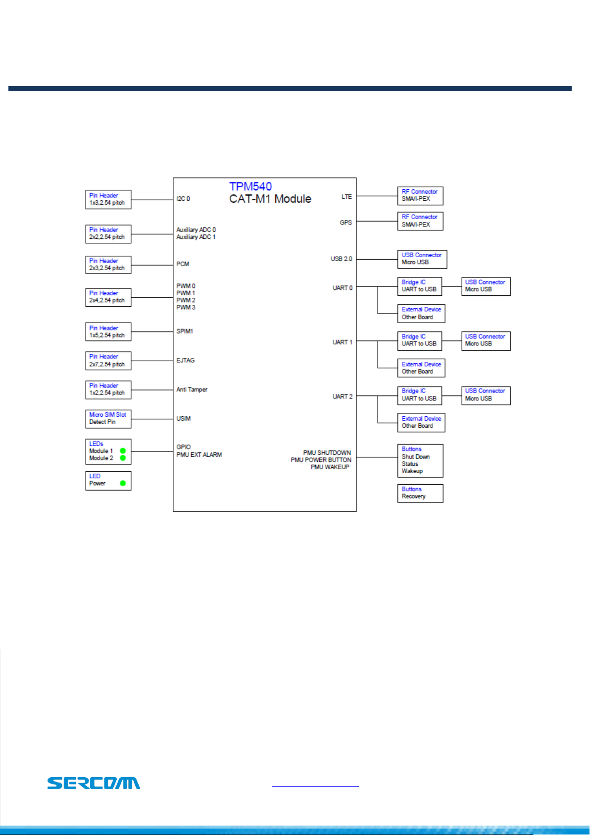
2.1. EVK Block Diagram
Figure 2.1 illustrates TPM540 EVK Block diagram and shows available interfaces for reference .
www.sercomm.com DOC-669671v1 5
Figure 2.1
Page 6

TPM540 EVK
Cat-M1/NB1 Module
Interface
Note
UART0/J3
AT commands UART interface, default baud rate: 115200
UART1/J2
Console Log UART interface, default baud rate: 115200
UART2/J7
CLI/Firmware upgrade UART interface, default baud rate: 115200
USIM/J17
SIM card solt, supports 3FF, micro SIM card
JP5
UART0 to USB/external MCU switch jump.
JP2
UART1 to USB/external MCU switch jump.
JP1
UART2 to USB/external MCU switch jump.
J19
TPM540 USB interface
S2
Power switch
J8/J21
RF_GNSS interface
J6/J11
RF_LTE interface
J1
5V DC input
2.2. EVK Interfaces
Table 2.2 lists TPM540 available interfaces on EVK for reference .
Table 2.2
www.sercomm.com DOC-669671v1 6
Page 7

TPM540 EVK
Cat-M1/NB1 Module
3. Starting with TPM540 EVK
3.1. Hardware preparation and setup
Attach the included antenna to the SMA connectorJ21
Plug-in the included DC adapter to DC Jack J1
Or each UART to USB cable.
Plug-in 3FF SIM card to J17(back side of EVK)
Switch on S2(Power switch) to turn on TPM540.
There is no need to turn on S2 while using USB cable to power up EVK
Figure 3.1
Module PWR1 LED will be lighted when turning on EVK successfully.
www.sercomm.com DOC-669671v1 7
Page 8

TPM540 EVK
Cat-M1/NB1 Module
3.2. Software preparation and setup
Prepare and install Silicon Lab CP210X UART to USB Driver, Version 6.7
(Please access Silicon Lab website to download driver.)
Prepare Serial Port Terminal Tool (Putty, SecureCRT, Teraterm..etc)
3.3. Starting to access EVK and TPM540
Turn on EVK
Connect UART0 to PC via USB cable.
Setup Terminal tools, please refer figure 3.3
COM port: com port will be enumerated on Windows device manager
Setting Baud rate for UART0: default is 115200.
Figure 3.3 for putty setting.
Opening terminal tools and sending AT command from UART.
www.sercomm.com DOC-669671v1 8
Page 9

TPM540 EVK
Cat-M1/NB1 Module
4. Button introduce
4.1. RECOVERY button:
This button is used to enter boot ROM mode for firmware upgrade and recovery system
when device cannot boot up by some reason.
Please visit Sercomm technical support website and issue a ticket when you have problem
with boot up your TPM540.
4.2. WAKEUP button:
This button is connecting to PMU_WAKEUP ping and used to wakeup TPM540 while device is
under power saving mode.
When there is no traffic, TPM540 will get into power saving mode immediately and TPM540
cannot receive and deal any commands from host. Please push the button to wakeup
module and send AT commands.
4.3. RESET button:
This button is connecting to PMU_SHUTDOWN pin for initiating power cycle that resets the
device or shutdowns device. (For reset function, please pull low button at least 100ms)
4.4. STATUS button:
This button is connecting to PMU_POWER_BUTTON pin and it can be used to either go into
power down mode when device is awake or waking up the device from low power mode.
While PMU_SHUTDOWN and PMU_WAKEUP cause an immediate action,
PMU_POWER_BUTTON reaction is not immediate and involves SW response.
www.sercomm.com DOC-669671v1 9
Page 10

TPM540 EVK
Cat-M1/NB1 Module
5. LED status
5.1. Module_PWR1 LED:
For VCC status indication.
ON: VCC is present.
OFF: VCC is absent.
VCC is provided by 5V to 3.3V LDO.
5.2. Module_LED1:
This LED is controlled by PMU_EXT_ALARM pin, it can be used for alarming an external
host.
TBD
5.3. Module_LED2:
TBD
www.sercomm.com DOC-669671v1 10
Page 11

TPM540 EVK
Cat-M1/NB1 Module
6. Special hardware configuration pins
6.1. SWD(JP17): TBD
SWDAT and SWCLK switch
6.2. Isolation control(JP3):
3.3V to 1.8V level shift ICs(U3,U10,U11) control.
H: Turn off level shift ICs
L: Turn on level shift ICs
Defualt is connected to Low.
6.3. Debug Selection(JP12):
HW pin for EJTAG chain select:
PD for MIPS chain.
PU for ARM chain.
Default setting is internal PD in TPM540.
6.4. Anti Tamper(JP11): TBD
User can connect PMU_AT_OUT to PMU_AT_IN in order to protect its device or module from
tampering.
Default setting is floating on EVK.
www.sercomm.com DOC-669671v1 11
Page 12

TPM540 EVK
Cat-M1/NB1 Module
7. Firmware Upgrade
TBD
www.sercomm.com DOC-669671v1 12
Page 13

TPM540 EVK
Cat-M1/NB1 Module
8. Federal Communication Commission Interference Statement
This device complies with Part 15 of the FCC Rules. Operation is subject to the following two
conditions: (1) This device may not cause harmful interference, and (2) this device must accept any
interference received, including interference that may cause undesired operation.
This equipment has been tested and found to comply with the limits for a Class B digital device,
pursuant to Part 15 of the FCC Rules. These limits are designed to provide reasonable protection
against harmful interference in a residential installation. This equipment generates, uses and can
radiate radio frequency energy and, if not installed and used in accordance with the instructions, may
cause harmful interference to radio communications. However, there is no guarantee that interference
will not occur in a particular installation. If this equipment does cause harmful interference to radio or
television reception, which can be determined by turning the equipment off and on, the user is
encouraged to try to correct the interference by one of the following measures:
Reorient or relocate the receiving antenna.
Increase the separation between the equipment and receiver.
Connect the equipment into an outlet on a circuit different from that to which the receiver is
connected.
Consult the dealer or an experienced radio/TV technician for help.
FCC Caution:
Any changes or modifications not expressly approved by the party responsible for compliance could
void the user's authority to operate this equipment.
This transmitter must not be co-located or operating in conjunction with any other antenna or
transmitter.
Radiation Exposure Statement:
This equipment complies with FCC radiation exposure limits set forth for an uncontrolled environment.
This equipment should be installed and operated with minimum distance 20cm between the radiator &
your body.
This device is intended only for OEM integrators under the following conditions:
1) The antenna must be installed such that 20 cm is maintained between the antenna and users,
and
2) The transmitter module may not be co-located with any other transmitter or antenna.
As long as 2 conditions above are met, further transmitter test will not be required. However, the OEM
integrator is still responsible for testing their end-product for any additional compliance requirements
required with this module installed
IMPORTANT NOTE: In the event that these conditions can not be met (for example certain laptop
configurations or co-location with another transmitter), then the FCC authorization is no longer
considered valid and the FCC ID can not be used on the final product. In these circumstances, the
OEM integrator will be responsible for re-evaluating the end product (including the transmitter) and
www.sercomm.com DOC-669671v1 13
Page 14

TPM540 EVK
Cat-M1/NB1 Module
obtaining a separate FCC authorization.
End Product Labeling
This transmitter module is authorized only for use in device where the antenna may be installed such
that 20 cm may be maintained between the antenna and users. The final end product must be labeled
in a visible area with the following: “Contains FCC ID: P27-TPM540”. The grantee's FCC ID can be
used only when all FCC compliance requirements are met.
Manual Information To the End User
The OEM integrator has to be aware not to provide information to the end user regarding how to install
or remove this RF module in the user’s manual of the end product which integrates this module. The
end user manual shall include all required regulatory information/warning as show in this manual.
This module can only be used with a host antenna circuit trace layout design in strict compliance with
the OEM instructions provided.
www.sercomm.com DOC-669671v1 14
 Loading...