

Page 1
Verizon LTE
UE Tester
Model: INTTP20213425
Quick Installation Guide
Manufacture By:
Sercomm Corporation
8F, No. 3-1, YuanQu Street, Nankang,
Taipei 115, Taiwan, R.O.C.
Page 2

Page 3

Table of Contents
CHAPTER 1 INTRODUCTION .............................................................................................. 1
Package Contents .............................................................................................................. 1
Key Feature ........................................................................................................................ 1
LEDs ................................................................................................................................... 2
Rear Panel .......................................................................................................................... 3
CHAPTER 2 INITIAL INSTALLATION............................................................................... 4
Procedure ........................................................................................................................... 4
CHAPTER 3 SPECIFICATIONS ............................................................................................ 5
General Specification ........................................................................................................ 5
RF Characteristics ............................................................................................................. 5
Regulatory Requirements ................................................................................................. 6
Safety Information............................................................................................................. 7
Device Surface Cleaning ................................................................................................... 9
Accessories ....................................................................................................................... 10
i
Page 4

Page 5
1
Chapter 1
Introduction
This Chapter provides an overview of the device's features and capabilities.
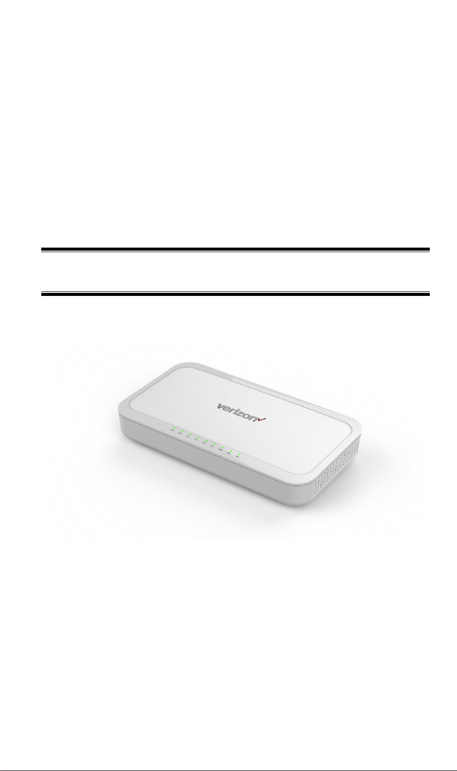
The LTE INTTP20213425 series UE Tester is a Desktop Small Cell LTE Device Tester
handles multiple scenarios, running different protocols simultaneously, and provides a complete,
independent solution.
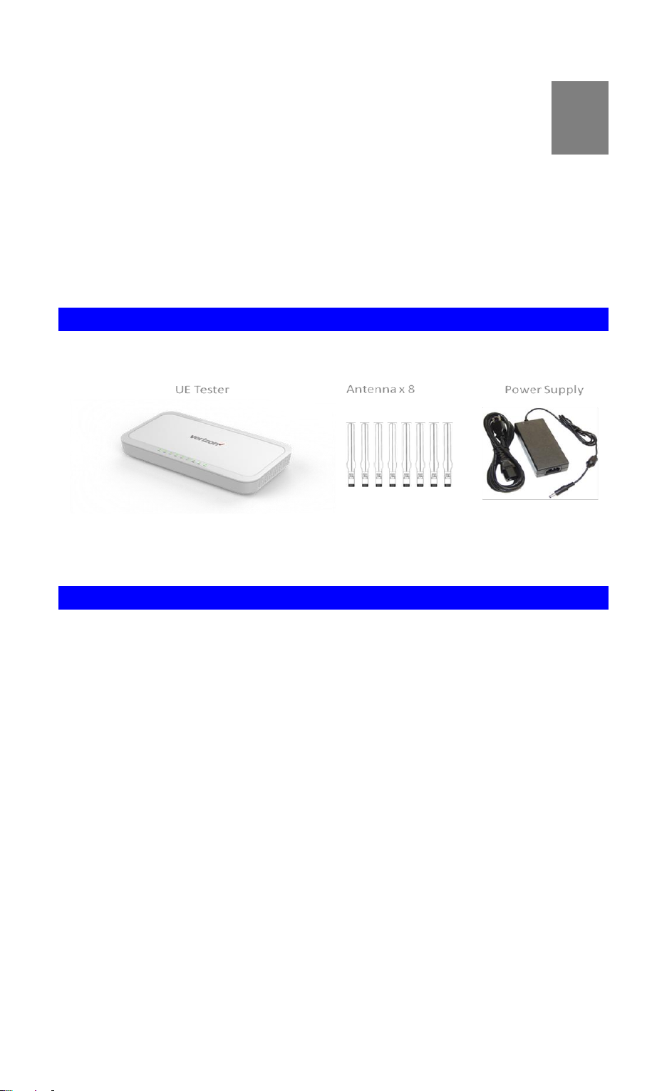
Package Contents
The following items should be included:
If any of the above items are damaged or missing, please contact your dealer immediately.
Key Feature
Designed for indoor lab test equipment deployment
Dual Intel T3100 chipset
Total 2GB RAM (1 GB RAM per each T3100)
Support up to 4 concurrent LTE bands
Support 4 Gigabit Ethernet Ports with RJ45 connector
Support 8 External RF antenna with Transmission output at 17dBm per RF ports
Support 2 External RF GPS antenna
1
Page 6

POWER (Red)
On - Power On/Normal Operation
Off - Power off
WAN1 (Red/Green)
On Green - CPU1 LAN active
On Red - CPU1 LAN inactive
WAN2 (Red/Green)
On Green – CPU2 LAN active
On Red – CPU2 LAN inactive
RF1 (Red/Green)
On Green – Band RF1 in service
On Red – Band RF2 RF not in service
RF2 (Red/Green)
On Green – Band RF2 in service
On Red – Band RF2 RF not in service
RF3 (Red/Green)
On Green – Band RF3 in service
On Red – Band RF3 RF not in service
RF4 (Red/Green)
On Green – Band RF4 in service
On Red – Band RF4 RF not in service
GPS1 (Red/Green)
On Green – GPS in service
On Red – GPS RF not in service
GPS2 (Red/Green)
On Green – GPS in service
On Red – GPS RF not in service
LEDs
Top-mounted LED
2
Page 7

Power
Input: 12 Vdc, 9A, Power Jack to Power Adaptor
Reset 1
This button is used to reset or restore to factory default for CPU1
Reset 2
This button is used to reset or restore to factory default for CPU1
Ethernet
Use standard LAN cable (RJ45 connectors) to connect to backhaul
/broadband router
RF1 Band
SMA connection for Band RF1 External Antennas
RF2 Band
SMA connection for Band RF2 External Antennas
RF3 Band
SMA connection for Band RF3 External Antennas
RF4 Band
SMA connection for Band RF4 External Antennas
GPS1
SMA connection for GPS1 External Antennas
GPS2
SMA connection for GPS2 External Antennas
Rear Panel
3
Page 8

2
Chapter 2
Initial Installation
This Chapter covers the software installation of the device.
Procedure
1. External Antenna
Connect the external antennas (total 8 included in the package) to antenna connector
ports.
2. Power Up
Connect the supplied power adapter to the UE Tester. Use only the power adapter provided. Using a different one may cause hardware damage.
3. Connect LAN Cable
Use a standard LAN cable to connect the device to the Ethernet port on the UE Tester
and to LAN/PC
4. Check the LEDs
The Power LED should be ON.
WAN1, WAN2 LED should be ON
RF1/RF2/RF3/RF4 should be ON depend on the UE test case scenario
4
Page 9

Connectivity
- 10x SMA RF connector for External Antennas
- Four Gigabit Ethernet LAN ports
Power Supply
External Power Adapter:
Input: AC100~240V~1.6A, 50Hz/60Hz, Altitude 0 to 5000
Meters
Output: 12 Vdc, 9A
Operating Requirement
Operating Temp. 0ºC to 40ºC
Storage Temp. -5ºC to 45ºC
Operating Humidity 5% to 90% Non-Condensing
Storage Humidity 5% to 95% Non-Condensing
Reset button
Two
LED
9 LED for Status.
Housing
426mm(W)x236mm(H)x65mm(D)
Parameter
UMTS
Frequency
FDD:
Band 13: DL/UL: 746~756MHz /777~787MHz
Band 4: DL/UL: 2100~2155MHz / 1710~1755MHz
Band 2(DL/UL: 1930~1990MHz / 1850~1990MHz)
Band 5(DL/UL: 869~894MHz / 824~849MHz)
Bandwidth
CPU1:
CA Band RF1 + Band RF2
CPU2:
CA Band RF3 + Band RF4
Beamwidth
External Omni Antennas
Power rating
+17dBm (50mW) per Antenna.
3
Chapter 3
Specifications
General Specification
RF Characteristics
5
Page 10

類別
Area
Standard
Note
EMC
USA
FCC Part 15B
RF
USA
FCC Part
24E/27/22H/27F
Regulatory Requirements
FCC Statement
This device complies with Part 15 of the FCC Rules. Operation is subject to the following two
conditions:
(1) This device may not cause harmful interference, and
(2) This device must accept any interference received, including interference that may cause
undesired operation.
This equipment generates uses and can radiate radio frequency energy and, if not installed and
used in accordance with the instructions, may cause harmful interference to radio communications. However, there is no guarantee that interference will not occur in a particular installation.
If this equipment does cause harmful interference to radio or television reception, which can be
determined by turning the equipment off and on, the user is encouraged to try to correct the
interference by one of the following measures:
Reorient or relocate the receiving antenna.
Increase the separation between the equipment and receiver.
Connect the equipment into an outlet on a circuit different from that to which the receiver
is connected.
Consult the dealer or an experienced radio/TV technician for help.
To assure continued compliance, any changes or modifications not expressly approved by the
party responsible for compliance could void the user's authority to operate this equipment.
(Example - use only shielded interface cables when connecting to computer or peripheral
devices).
This transmitter must not be co-located or operating in conjunction with any other antenna or
transmitter.
FCC Radiation Exposure Statement
This equipment complies with FCC RF radiation exposure limits set forth for an uncontrolled
environment. This equipment should be installed and operated with a minimum distance of 20
centimeters between the radiator and your body.
6
Page 11

Signal word
Meaning
DANGER
Indicates an extremely hazardous situation which, if not avoided, will
result in death or serious injury.
WARNING
Indicates a hazardous situation which, if not avoided, could result in
death or serious injury.
CAUTION
Indicates a hazardous situation which, if not avoided, could result in
minor or moderate injury.
NOTICE
Indicates a hazardous situation not related to personal injury.
Safety Information
All instructions, warning and caution statements that accompany this equipment must be strictly
followed at all times to ensure its safe use. Observe all warning and caution symbols that are
fixed to this equipment. This electrical equipment is designed with the utmost care for the
safety of those who install and use it. However, when using this device, basic safety precautions
should always be followed to reduce the risk of fire and injury to persons, and the dangers of
electric shock and static electricity. Do not cover the device or block the airflow to the device
with any other objects. This product was qualified under test conditions that included the use of
the supplied cables between system components. To be in compliance with regulations, the user
must use the cables supplied with the unit and install them properly. This includes the power
adapter that is provided. Place the unit to allow for easy access when disconnecting the power
adapter from the mains wall outlet. Operate this product only with the type of power source
indicated on the marking label. If you are not sure of the type of power supplied to your home,
consult your dealer or local electricity company. Do not use this product near water, for example a swimming pool or a bathroom. Keep the device away from excessive heat and humidity
and keep the device free from vibration and dust. Wipe the unit with a clean, dry cloth. Never
use cleaning fluid or similar chemicals. Do not spray cleaners directly on the unit or use forced
air to remove dust. Avoid installing or using this product during an electrical storm. There may
be remote risk of electric shock from lightning. During a lightning storm for added protection
please unplug it from the wall outlet and disconnect all cables. This will prevent damage due to
lightning and power surges. For safety reasons, only authorized service technicians should open
the device. If the device is opened the warranty will become void. The device may affect
medical equipment and so please take account of any technology restrictions with this equipment. This device, like other radio devices, emits radio frequency electromagnetic energy, but
operates within the guidelines found in radio frequency safety standards and recommendations.
It is recommended that the minimum operating distance from the installed Access Point to
persons is 20cm.
General Hazard Statement
Safety notes are marked with symbols. Ignoring the safety notes may lead to personal injury,
damage to the instrument and malfunctions.
Signal Words identify the hazard severity level as follow:
Contact with energized parts can cause serious injury.
7
Page 12

At least one other trained person must be in attendance, who can immediately and safely
disconnect the system if necessary.
This second person must be trained in first aid for emergency purposes
Some parts of all electrical installations are energized. Failure to follow safe work
Practices and the safety warnings may lead to bodily injury and property damage.
For this reason, only trained and qualified personnel (electrical workers as defined in
IEC 60215 or EN 60215 + A1 or in the National Electrical Code or in ANSI/NFPA No. 10)
may install or service the installation.
Risk of electric shock
a) Do not open the AC adaptor housing. Make sure that the AC adapter does ot come in
contact with liquids.
b) Use Only the 3-pin power cord with equipment grounding conductor which was supplied
with your instrument and only on 3-pin grounded outlet must be used.
The Cooling vents at the right & left of the enclosure can become obstructed, preventing
ventilation of the enclosure.
Make sure that the air vent is not obstructed and remains clear at all times.
8
Page 13

Device Surface Cleaning
You may clean the device case using a cloth dampened with mild liquid detergent (such
as Dawn) and water.
Always unplug/disconnect power before apply any cleaning to 13245 UE Tester.
Warning Do not submerse the 13245 UE Tester or its accessories in water or allow wa-
ter to enter into the case; this may lead to electrical shock and/or damage
9
Page 14

Item
Description
P/N
AC/DC Adapter (without power core)
AC100~240V~1.6A, 50Hz/60Hz auto switching, 12
V DC, 9A
919902120PH
3-Pin Power Supply Cord US, with grounding conductor
459000B0IS
External Antenna
617202CPWY
Accessories
10
 Loading...