

SZ-DWS01
ZigBee Door Window Sensor
User Guide

Table of Contents
CHAPTER 1 INTRODUCTION...................................................................................... 1
Package Contents ................................................................................................1
Specfication .......................................................................................................... 1
CHAPTER 2 DEVICE DESCRIPTION .......................................................................... 2
Installation............................................................................................................. 2
Operation .............................................................................................................. 4
External contact wiring (Optional)...................................................................... 5
CHAPTER 3 REGULATORY APPROVAL................................................................... 7
Copyright 201 2. All Rights Reserved.
Document Version: 1.0
All trademarks and trade names are the properties of their respective owners.
ii
Chapter 1
Introduction
This Chapter provides an overview of the ZigBee Door/Window Sensor features
and capabilities.
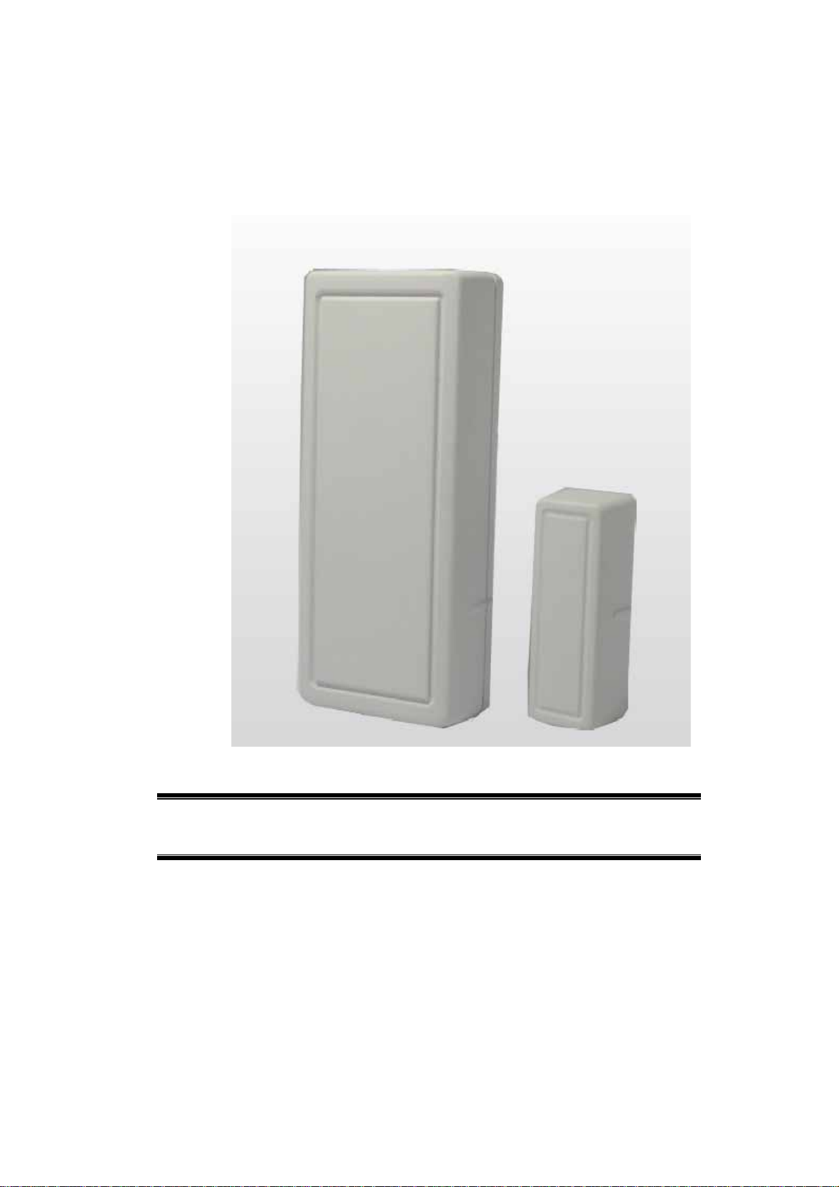
Congratulations on the purchase of your new ZigBee Door/Window Sensor. The ZigBee
Door/Window Sensor is a consumer electronic device, which is used for home monitoring and
security.
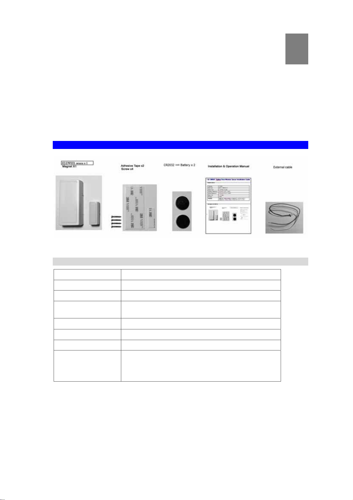
Package Contents
1
Specification
Frequency 2.4GHz
Batter Type DC 3V, CR2032 x 2
Magnet Type < 1.27 cm ( 0.5 inch )
Operating
Temperature
Storage Temperature
Battery Life 1 ~ 2 years
RF Range 100M
Dimention Main Unit: 13 mm x 20 mm x 115 mm (0.51" x 0.78" x
0° C to 50° C (32° - 122°F)
-20° C to 70° C (-4° - 158°F)
4.52")
Magnet Unit: 10 mm x 12mm x 47 mm (0.39" x 0.47" x
1.85")
1

Chapter 2
Device Description
This Chapter provides device description for the ZigBee Door/Window Sensor.
Installation
NOTE: Please make sure that the sensor and magnet is located less then 1.27cm (0.5 inch)
from each other.
2
Intallation
1. Hold the sensor near the top of the door, close to the opening edge of the door. This is the
mounting location for the sensor.
2. Using a flat head screw driver insert into the notch located on the case and gently twist to
open.
2

3. Insert CR2032 Battery
Use care when installing the battery and observe the correct polarity when the battery is inserted. Use only CR2032
batteries for replacement.
WARNING!: Battery may explode if mistreated. Do not recharge, disassemble or dispose of in fire.
4. Use either one of the following methods to install the sensor:
• Remove the back plate of the sensor; use this as the mounting bracket. Use the
screwdriver to secure the back plate to the wall with the screws provided.
• Use provided adhesive on the sensor. Attach the sensor to the door. Press firmly and
hold in place for a few seconds.
3

Magnet Setup
1. Attach the magnet on the location next to the sensor by using either one of the following
methods:
• Remove the back plate of the magnet; use this as the mounting bracket. Use the
screwdriver to secure the back plate to the wall with the screws provided.
• Use provided adhesive on the magnet. Attach the sensor to the door. Press firmly and
hold in place for a few seconds.
2. Make sure the alignment marks of both devices are facing each other.
Operation
4

• Join Function
For "Join" a network, please do the following instruction:
• Press the Join/Leave button for less than 1 second. The LED is blinking while
processing. If the sensor has been joined with the controller successfully, the Green
LED will be on for 2 seconds and then off. The Green LED will be off instantly if failed.
• Leave Function
For "Leave" a network, please do the following instruction:
• Press Join/Leave button for 3 seconds to let the sensor disassociate from the controller.
• The LED will stay off during the normal operation.
• The sensor is equipped with a tamper switch. If the cover of sensor is removed, the sensor
will send an alarm to the ZigBee controller. The sensor will be in "Awake" mode before
replacing
External contact wiring (Optional)
1.remove screw
2.Plug two-pin connector.
3.close screw
4. Connect wire to N/C dry reed switch device. (Option)
5

Use the following specifications for the external reed switch device.
• Maximum wire length:1 m
6

Chapter 3
This equipment has been tested and found to comply with the limits for a Class B digital device, pursuant to part 15 of
the FCC
rules. These limits are designed to provide reasonable protection against harmful interference in a residential
installation. This
equipment generates, uses and can radiate radio frequency energy and, if not installed and used in accordance with the
instructions, may cause harmful interference to radio communications. However, there is no guarantee that
interference will not
occur in a particular installation. If this equipment does cause harmful interference to radio or television reception,
which can be
determined by turning the equipment off and on, the user is encouraged to try to correct the interference by one or
more of the
following measures:
-Reorient or relocate the receiving antenna.
-Increase the separation between the equipment and receiver.
You are cautioned that changes or modifications not expressly approved by the party responsible for compliance could void your
authority to operate the equipment.
This device complies with Part 15 of the FCC Rules. Operation is subject to the following two conditions: (1) this device may
not cause harmful interference and (2) this device must accept any interference received, including interference that may cause
undesired operation
This Transmitter must not be co-located or operating in conjunction with any other antenna or transmitter.
This equipment complies with FCC RF radiation exposure limits set forth for an uncontrolled environment . This
equipment should be installed and operated with a minimum distance of 20 centimeters between the radiator and your
body.
REGULATOR Y APPROVAL
The FCC Statement
FCC Radiation Exposure Statement
7

CE Approval
CE Standards
This product complies with the 99/5/EEC directives, including the following safety and EMC
standards:
• EN30 0328-2
• EN30 1489-1/-17
CE Marking Warning
This is a Class B product. In a domestic environment this product may cause radio interference
in which case the user may be required to take adequate measures.
UL Notices: This device complies with UL Standard UL634.
8
 Loading...