

Page 1
FCC ID:P27SCE2R0
SCE2R0-29
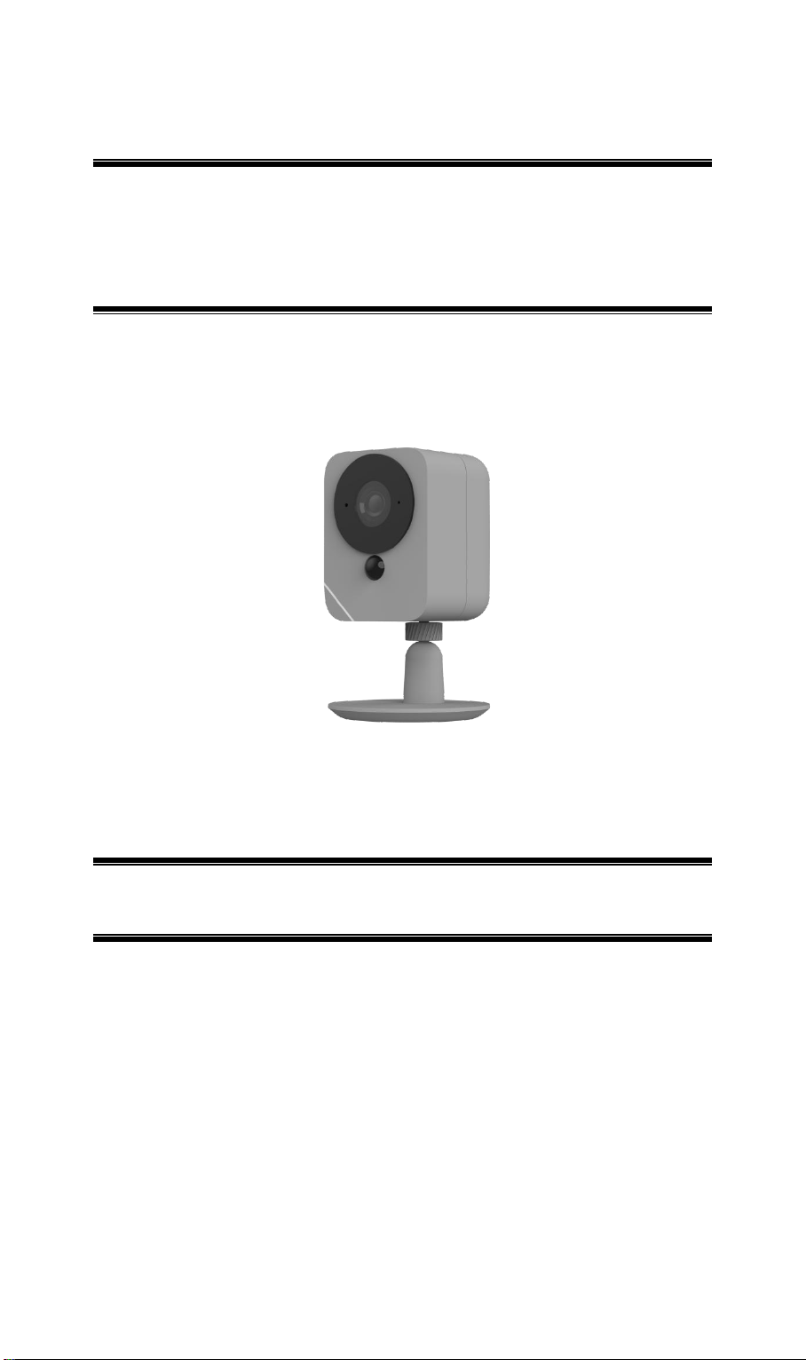
Outdoor Camera
Setup Guide
Document Version: 1.0
Page 2

CC ID:P27SCE2R0
F
Table of Contents
Chapter 1 Introduction .......................................................................................................... 1
Package Contents .............................................................................................................. 1
Chapter 2 Setup ...................................................................................................................... 2
System Requirements ........................................................................................................ 2
Physical Details – Smart Video Camera .......................................................................... 2
Pre-Installation ................................................................................................ .................. 5
Installation ......................................................................................................................... 7
Mounting Installation........................................................................................................ 7
Chapter 3 Viewing Live Video ............................................................................................. 8
Overview ............................................................................................................................ 8
Requirements ..................................................................................................................... 8
Connecting to a Camera on your LAN ............................................................................ 8
Appendix A Specifications ................................................................................................. 10
SCE2R0-29 Battery Camera .......................................................................................... 10
Regulatory Approvals ..................................................................................................... 11
CC ID:P27SCE2R0
F
Page 3
1
CC ID:P27SCE2R0
F
Chapter 1
Introduction
Package Contents
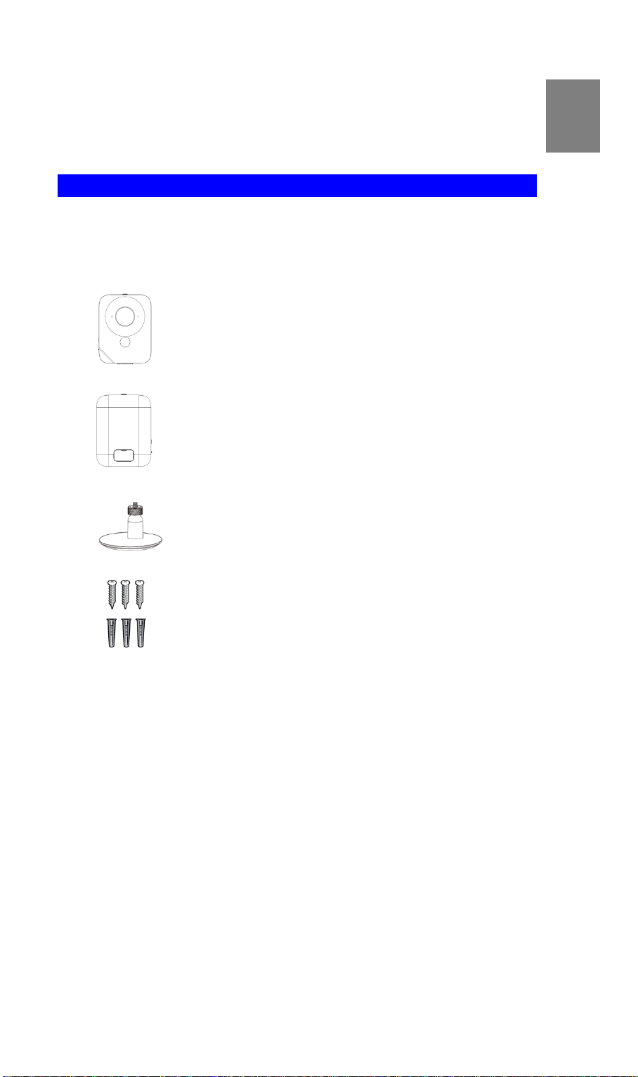
The following items should be included: If any of these items are damaged or missing, please
contact your dealer immediately.
1. SCE2R0-29 Battery Camera x 1
2. Battery Pack x 1
3. Mounting Stand x 1
4. Screw/Anchor x 3
1
Page 4
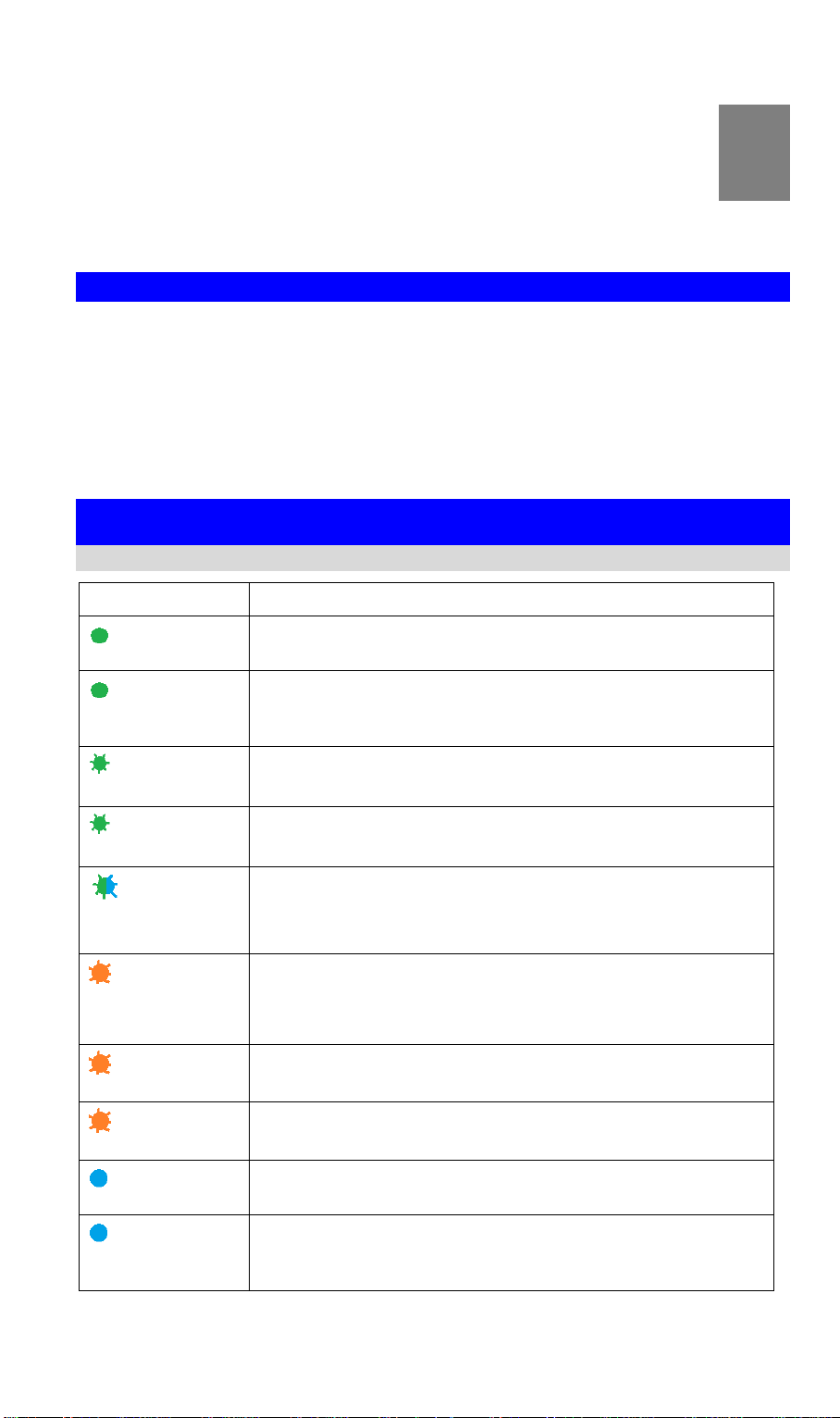
Color
Status
Solid Green
The camera is registered and connected to the network.
Solid Green
(5 seconds)
WPS pairing is failed. The camera can not access to the Wi-Fi
network.
Blinking Green
WPS pairing (PBC code mode)
Fast Blinking Green
WPS pairing (pin code mode)
Blinking
Green/Blue
The camera is receiving a firmware/MCU upgrade.
Blinking Red
The camera is connecting to the network and cloud.
The camera cannot access to the network and cloud.
Low Battery alarm: once blinking per 2 seconds.
Slow Blinking Red
The SD card is invalid.
Fast Blinking Red
When the Reset button is pressed for 10 seconds, the LED will
blink red indicating the start of the reboot/factory reset.
Solid Blue
The camera is powering on.
Solid Blue
(1 second)
The PIR is triggered.
2
CC ID:P27SCE2R0
F
Chapter 2
Setup
This Chapter provides details on how to install and configure the Battery
Camera.
System Requirements
A computer or mobile device with Internet access
You can use the following web browser while using a computer:
• Internet Explorer 7 or later
• Firefox 3
• Safari 4
• Chrome
Physical Details – Smart Video Camera
LED
2
Page 5

Front Panel
Microphone
The built-in microphone is useful for bi-direction voice
conversation.
Light Sensor
This is hardware sensor to detect LUX.
Lens
No physical adjustment is required or possible for the lens, but
you should ensure that the lens cover remains clean. The image
quality is degraded if the lens cover is dirty or smudged.
IR LEDs
They are used to provide illumination for night time.
PIR Sensor
This is hardware sensor for detecting motion.
Micro USB Connector
This connector is used for charging the power. Connect the
Micro USB cable to this port.
CC ID:P27SCE2R0
F
Rear Panel
3
Page 6

Side Panel
Reset/WPS
This button has two functions:
WPS:
-WPS PBC Mode: When pressed and released (less then 3
seconds), the Camera will be in the WPS PBC mode (Auto
link mode).
-WPS Pin Code Mode: When pressed and held for over 3
seconds, the Camera will be in the WPS Pin Code mode.
Reset: When pressed and held over 10 seconds, the LED will
be flashing red, which means the settings of Camera will be
set to their default values.
SD Card Slot
Insert the SD card for external storage. Use a screwdriver to remove
the screw and open the cover to insert the SD card if needed.
CC ID:P27SCE2R0
F
CAUTION:
Risk of fire and burns under certain conditions
Do not open, crush, short circuit and keep away from heat.
Risk of explosion if the battery replaced by in incorrect type
Follow instructions while using the battery
Dispose of used batteries according to the instructions
This product is intended to be supplied by a Listed Power Adapter or DC power source,
whose output meets LPS, rated 5Vdc, 2A minimum and Tma 50 degree C, if need further
assistance with purchasing the power source please contact Sercomm Corp. for further
information.
4
Page 7

Pre-Installation
CC ID:P27SCE2R0
F
Insert the Battery Pack
Align the battery contacts and then insert the battery pack into the camera.
Note: Be sure to charge the battery when use it for the first time.
5
Page 8

Color
Status
Solid Green
The charging is complete.
Solid Red
The battery pack is charging.
CC ID:P27SCE2R0
F
Battery Pack Charging
You can charge your camera battery indoors using the Micro USB cable.
Note: For safety reasons, the battery charging temperatures are from 5°C to 35°C.
1. Put the battery pack into the camera.
2. Connect the power Micro USB cable to the USB port of the camera.
3. Plug the other end of power Micro USB cable into power adaptor for charging.
Battery Pack LED
Remove the Battery Pack
1. Push the button.
2. Remove the battery pack from the camera.
6
Page 9

CC ID:P27SCE2R0
F
Installation
1. Move the camera to where it is to be placed.
2. Check the LED:
The LED light bar should be solid blue when the camera is powering on.
Mounting Installation
Place the camera in a flat surface or mount it on the wall/ceiling.
Check the network signal strength in the place where you want to locate the camera.
Avoid placing the camera in an area that gets a lot of light directly into the camera lens.
Wall Mounting
1. Identify the location for mounting the Camera.
2. Place the mounting plate and secure it with three screws.
Note: Use anchors if necessary.
3. Attach the camera onto the camera stand.
7
Page 10

3
CC ID:P27SCE2R0
F
Chapter 3
Viewing Live Video
This Chapter provides basic information about viewing live video.
Overview
This Chapter has details of viewing live video using Internet Explorer.
Requirements
To view the live video stream generated by Battery Camera, you need to meet the following
requirements:
Windows XP, 32-bit Windows Vista/Windows 7.
Internet Explorer 7 or later, Firefox 3.0 or later.
Connecting to a Camera on your LAN
To establish a connection from your PC to Battery Camera:
1. Start Internet Explorer.
2. In the Address box, enter "HTTP://" and the IP Address of Battery Camera.
3. You will then be prompted for a username and password.
If using the default values, enter administrator for the name, and leave the
password blank.
Otherwise, enter the Administrator ID and Administrator Password set on the
Maintenance screen.
4. When you connect, the following screen will be displayed.
5. Click View Video.
6. If the Administrator has restricted access to known users, you will then be prompted for a
Figure 1: Home Screen
username and password.
Enter the name and password assigned to you by Battery Camera administrator.
8
Page 11

CC ID:P27SCE2R0
F
7. The first time you connect to the camera, you will be prompted to install decoders.
Choose "I accept the terms of the license agreement" and click "OK".
8. Video will start playing automatically. There may be a delay of a few seconds while the
video stream is buffered.
9
Page 12

Appendix A
Model
Dimensions
(H x W x D)
72mm x 93mm x 71.35mm
Operating Temperature
-10 C to 50 C
Charging Temperature
5 C to 35 C
Storage Temperature
-20 C to 50 C
Network Protocols
TCP/IP, HTTP, HTTPS, DHCP, NTP, RTP, RTCP, RTSP, DNS
Network Interface
IEEE 802.11b/g/n
IR LED
2
LEDs
3
Microphone
1 built-in Microphone
Button
1
Micro-SD Card slot
1 (w/o Micro-SD inside)
Speaker
1
Power Adapter
5V / 2A, 100 - 240V
Battery (C1-04)
1, Minimum capacity 6140 mAh (22.2Wh)
Micro-USB Cable
1M Cable
Specifications
SCE2R0-29 Battery Camera
SCE2R0-29
C ID:P27SCE2R0
FC
● Any changes or modifications not expressly approved by the party responsible for
compliance could void the authority to operate equipment.
● This device and its antenna must not be co-located or operating in conjunction with any other
antenna or transmitter.
● For product available in the USA/Canada market, only channel 1~11 can be operated.
Selection of other channels is not possible
10
Page 13

CC ID:P27SCE2R0
F
Regulatory Approvals
FCC Statement
This equipment generates, uses and can radiate radio frequency energy and, if not installed and
used in accordance with the instructions, may cause harmful interference to radio
communications. However, there is no guarantee that interference will not occur in a particular
installation. If this equipment does cause harmful interference to radio or television reception,
which can be determined by turning the equipment off and on, the user is encouraged to try to
correct the interference by one of the following measures:
Reorient or relocate the receiving antenna.
Increase the separation between the equipment and receiver.
Connect the equipment into an outlet on a circuit different from that to which the receiver
is connected.
Consult the dealer or an experienced radio/TV technician for help.
To assure continued compliance, any changes or modifications not expressly approved by the
party responsible for compliance could void the user's authority to operate this equipment.
(Example - use only shielded interface cables when connecting to computer or peripheral
devices).
FCC Radiation Exposure Statement
This equipment complies with FCC RF radiation exposure limits set forth for an uncontrolled
environment. This equipment should be installed and operated with a minimum distance of 20
centimeters between the radiator and your body.
This device complies with Part 15 of the FCC Rules. Operation is subject to the following two
conditions:
(1) This device may not cause harmful interference, and
(2) This device must accept any interference received, including interference that may cause
undesired operation.
This transmitter must not be co-located or operating in conjunction with any other antenna or
transmitter.
11
 Loading...