

Page 1
SCB1R0-29xxxxx(the 1st x
should be "blank" or "-";
the rest x could be 0 to 9, A
to Z, a to z, "blank" or "-",
for the marketing purpose)
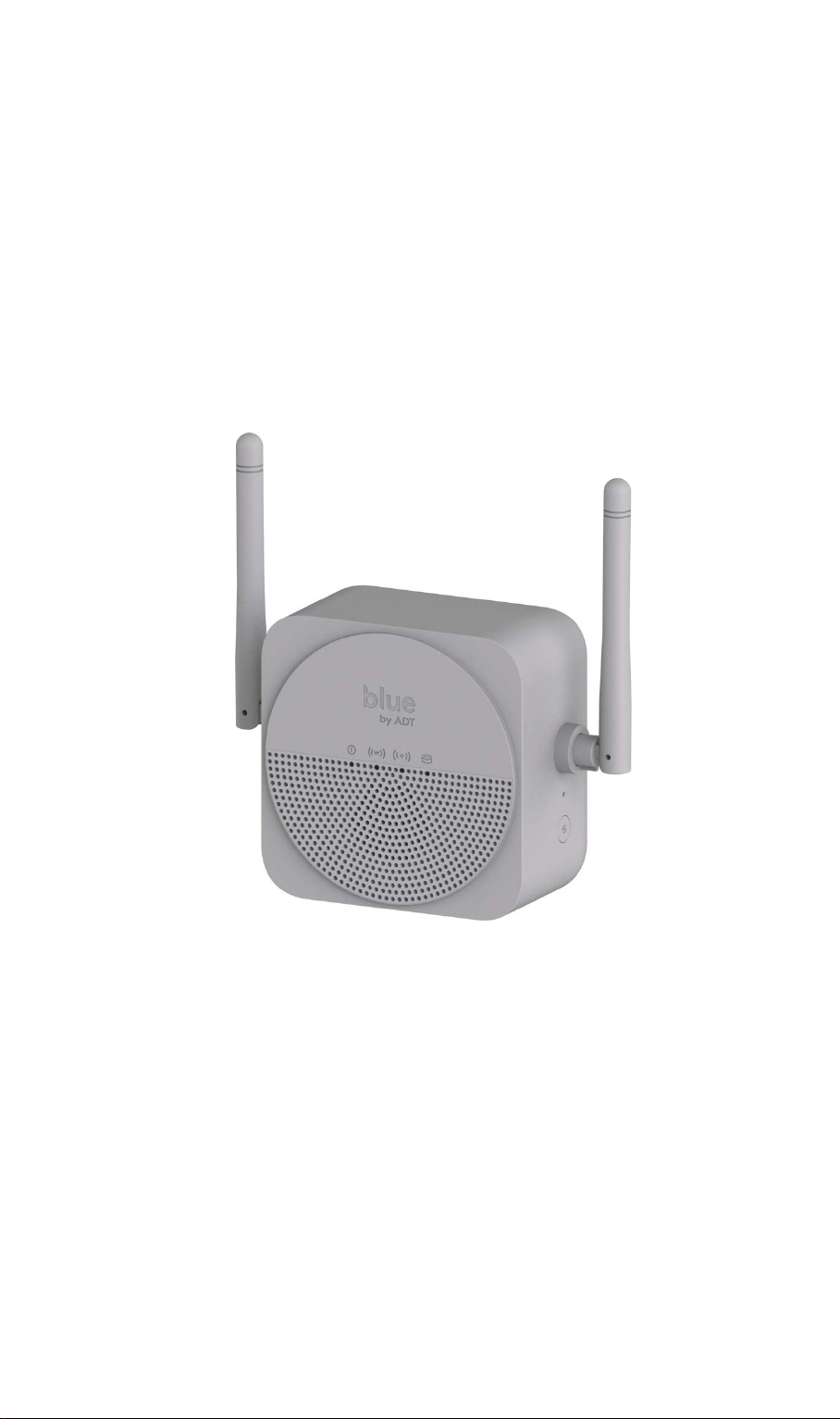
Camera Hub
(WiFi Extender)
FCC ID: P27SCB1R0
i
Page 2

FCC ID: P27SCB1R0
User Guide
Table of Contents
CHAPTER 1 INTRODUCTION.............................................................................................. 3
Package Contents .............................................................................................................. 3
Features .............................................................................................................................. 3
LEDs ................................................................................................................................... 4
CHAPTER 2 INITIAL INSTALLATION .............................................................................. 6
Requirements ..................................................................................................................... 6
Procedure ........................................................................................................................... 6
CHAPTER 3 CONFIGURATION ........................................................................................... 7
Configuration ..................................................................................................................... 7
APPENDIX A SPECIFICATIONS .......................................................................................... 8
Camera Hub ....................................................................................................................... 8
Regulatory Approvals ....................................................................................................... 9
opyright 2019. All Rights Reserved.
C
Document Version: 1.0
All trademarks and trade names are the properties of their respective owners.
ii
Page 3

FCC ID: P27SCB1R0
1
Chapter 1
Introduction
This Chapter provides an overview of the Camera Hub’s features and capabilities.
Congratulations on the purchase of your new Camera Hub (WiFi extender). The WiFi extender
is a consumer electronic device, which is designed to extend the WiFi signal for all appliances
of your home, major from IP cameras, and video doorbells. It allows you to increase WiFi
speed and range by taking the signal from a home router and retransmit to the furthest corner of
your house. Most of the devices can be paired with the extender by just pressing one button.
Package Contents
The following items should be included:
Camera Hub Unit x 1
I
f any of the above items are damaged or missing, please contact your dealer immediately.
Features
MT7620DA processor with 32MB Flash and 64MB RAM
Bluetooth 4.2
Extend WiFi Range
Smart LED Indicators
Two External Antennas
WPS Function
Easy to Install
Compact Design
3
Page 4

LEDs
Front Panel
The Camera Hub has 4 LEDs.
FCC ID: P27SCB1R0
POWER (Blue)
On - Power On/Normal Operation
Off - Power Off
Flashing - Booting
LAN (Blue) On - WiFi normal operation
Off - WiFi disable
Flashing - WPS active (follow WiFi standard) or WiFi
T
raffic
WAN (Blue) On - Connected to the Internet
Off - Not connected to the Internet
Flashing - Connecting to the Internet
DEVICE (Blue) On - Connected to a IP Camera or a Doorbell device
Off - Not connected to a device
Flashing - Paring to a new device
4
Page 5

Appendix B - About Wireless LANs
Push the WPS button more than 3 seconds to trigger WPS pairing
successfully connected.
Rear/Side Panel
ower Plug Connect the power plug to a wall socket.
P
Reset This button has two (2) functions:
• Reboot. When pressed and released, the Camera Hub will reboot
(restart).
• Clear All Data. This button can also be used to clear ALL dat
a
nd restore ALL settings to the factory default values.
To Clear All Date and restore the factory default values:
1. Power On.
2. Keep holding the Reset But t on down for 3 seconds.
Release the Reset Button. The Camera Hub is now using the factory
default values.
WPS Button
process with voice (PBC mode).
During the pairing process, the LAN LED will fast blink until WiFi is
a
5
Page 6

FCC ID: P27SCB1R0
2
Chapter 2
Initial Installation
This Chapter covers the device installation of the WiFi extender.
Requirements
• None of cables required for the installation.
Procedure
1. Choose an Installation Site
Select a suitable place to install the Camera Hub.
2. Power Up
Place the extender near the existing router. Provide the power to the extender so plug it into a wall socket or a power strip. The LEDs light will be ON and make a welcome sound to
notice the extender is boot up successfully.
3. Check the LEDs
• All 4 LEDs shall be ON when the power is supplied to the extender.
• The Power LED should be ON
• The LAN LED should be ON
• The WAN LED should be ON
• The Device LED should be ON
6
Page 7

Appendix B - About Wireless LANs
3
Chapter 3
Configuration
This Chapter provides Setup details of the WiFi extender.
Configuration
The WiFi extender can offer customers with extending wireless communication between
devices and the router wherever at home. This extender is designed to provide reachable
network connection with all certified devices especially for IP cameras, security doorbells and
other WiFi devices.
Configuring WiFi extender via WPS Button
In this case, make sure an existing router. Follow the steps given below.
• Allocate the extender to a near router or an AP. Power on the extender; plug it into the
wall socket or a power strip. It is recommended to press the WP S button on the extender
within 2 minutes after you have pressed the WPS button on your router or AP.
• To confirm the pairing process done successfully, check the LAN LED light is fast blink-
ing. Also see the WPS LED light on your router, it will stark blinking.
• It will take for a while (about 2 minutes) then will get connected to the router. The extend-
er WAN LED light up after successful Internet connection between the two devices.
7
Page 8

Appendix A
A
Specifications
Camera Hub
Model Camera Hub (WiFi Extender with Chime)
Dimensions 130mm (H) x 128mm (W) x 72mm (D)
FCC ID: P27SCB1R0
Operating Temperature
Buttons 2 (1 Reset, 1 WPS button)
Network Protocol: TCP/IP, 802.11 b/g/n
Bluetooth
LEDs 4
Power Input 100~120VAC, 60Hz
0°C - 40°C (32°F - 104°F)
4.2
8
Page 9

Regulatory Approvals
FCC Statement
Federal Communication Commission Interference Statement
This equipment has been tested and found to comply with the limits for a Class B digital device,
pursuant to Part 15 of the FCC Rules. These limits are designed to provide reasonable protection against harmful interference in a residential installation. This equipment generates, uses
and can radiate radio frequency energy and, if not installed and used in accordance with the
instructions, may cause harmful interference to radio communications. However, there is no
guarantee that interference will not occur in a particular installation. If this equipment does
cause harmful interfe re nc e to radio or television reception, which can be determined by turning
the equipment off and on, the user is encouraged to try to correct the interference by one of the
following measures:
- Reorient or relocate the receiving antenna.
- Increase the separation between the equipment and receiver.
- Connect the equipment into an outlet on a circuit different from that to which the
receiver is connected.
- Consult the dealer or an experienced radio/TV technician for help.
FCC Caution: Any changes or modifications not expressly approved by the party responsible
for compliance could void the user's authority to operate this equipment.
This device complies with Part 15 of the FCC Rules. Operation is subject to the following two
conditions: (1) This device may not cause harmful interference, and (2) this device must accept
any interference received, including interference that may cause undesired operation.
IMPORTANT NOTE:
Radiation Exposure Statement:
This equipment complies with FCC radiation exposure limits set forth for an uncontrolled
environment. This equipment should be installed and operated with minimum distance 20cm
between the radiator & your body.
This transmitter must not be co-located or operating in conjunction with any other antenna or
transmitter.
Country Code selection feature to be disabled for products m a rke ted to the US/CANADA
Operation of this device is restricted to indoor use only
9
Page 10

FCC ID: P27SCB1R0
● FCC RF Radiation Exposure Statement
This equipment complies with FCC radiation exposure limits set forth for an uncontrolled
environment. This equipment should be installed and operated with minimum distance 20cm
between the radiator & your body.
10
 Loading...