

Page 1
WiFi IP Camera
User’s Guide
Page 2

Page 3

Table of Contents
CHAPTER 1 INTRODUCTION.............................................................................................. 1
Overview ............................................................................................................................ 1
Physical Details - WiFi IP Camera .................................................................................. 2
Package Contents .............................................................................................................. 4
CHAPTER 2 BASIC SETUP ................................................................................................... 5
System Requirements ........................................................................................................ 5
Installation ......................................................................................................................... 5
Wall Mounting ................................................................................................................... 7
CHAPTER 3 VIEWING LIVE VIDEO ................................................................................ 10
Overview .......................................................................................................................... 10
Requirements ................................................................................................................... 10
Connecting to a Camera on your LAN .......................................................................... 10
APPENDIX A SPECIFICATIONS ........................................................................................ 12
WiFi IP Camera............................................................................................................... 12
Regulatory Approvals ..................................................................................................... 12
Copyright 2015. All Rights Reserved.
Document Version: 2.0
All trademarks and trade names are the properties of their respective owners.
i
Page 4

Page 5

1
Chapter 1
Introduction
This Chapter provides information of the WiFi IP Camera's features,
components and capabilities.
Overview
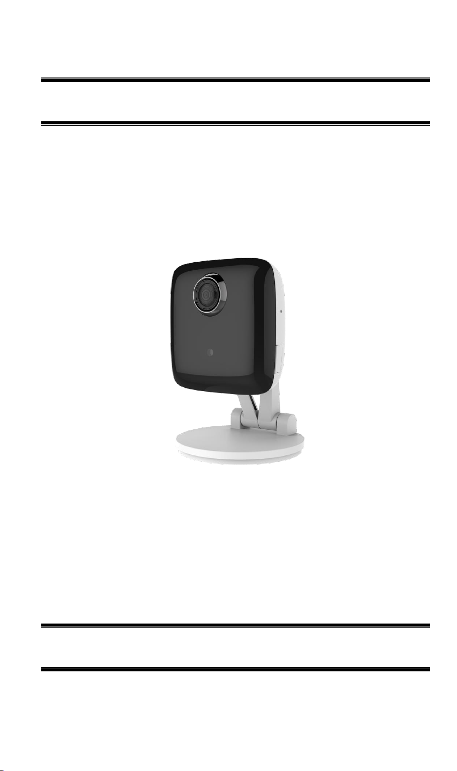
Congratulations on the purchase of your new WiFi IP Camera. The WiFi IP Camera is a
Day/Night WiFi IP Camera with 1080p resolution and 802.11ac WiFi connectivity. With builtin White Light LEDs, the WiFi IP Camera can provide illumination around 5 meters long
under low light conditions in a simple, economical manner.
The WiFi IP Camera also comes with smart zoom feature, which allows images to be zoomed
without losing picture quality. The central part of the picture is trimmed and enlarged without
image processing.
Moreover, the duo-hinge and compact design of the camera can be extended from the wall and
easily moved around, while still being firm enough to hold for odd angles.
Features
Standalone Design. The WiFi IP Camera is a standalone system with built-in CPU and
Video encoder. It requires only a power source and a connection to your Wireless iHub.
Dual Video Support. The WiFi IP Camera can support H.264 and MJEPG video for
different image compression.
Suitable for Home, Business or Public Facilities. Whether for Home, Business or
Public Facility surveillance, or just for entertainment and fun, the WiFi IP Camera has the
features you need.
IR LED Support. Each WiFi IP Camera has two infrared LEDs. The LEDs can provide
illumination around 5 meters long, that can help to output a better video quality while
under low-light conditions such as on cloudy days, or in the morning or evening.
Smart Zoom Support. With its 16x (QHD) optical zoom, you can move closer without
taking a single step, and the pictures captured by the image sensor of the camera are
enlarged without losing quality.
Wireless Features
Supports 802.11ac Wireless Standard. The 802.11ac standard provides backward
compatibility with the 802.11n standards. The WiFi IP Camera can work with all
802.11ac, 802.11n, 802.11b and 802.11g Wireless stations.
Supports WPS. WPS (Wi-Fi Protected Setup) can simplify the process of connecting you
WiFi IP Camera to your wireless network by using the push button configuration (PBC) on
the Wireless Access Point, or entering a PIN code if there's no button.
Wired and Wireless Network. The WiFi IP Camera can be connected either with wire
WPS Support. WPS (WiFi Protected Setup) can simplify the process of connecting any
or wirelessly to your network.
device to the wireless network by using the push button configuration (PBC) on the
Waterproof HD IP Camera, or entering a PIN code if there's no button.
1
Page 6
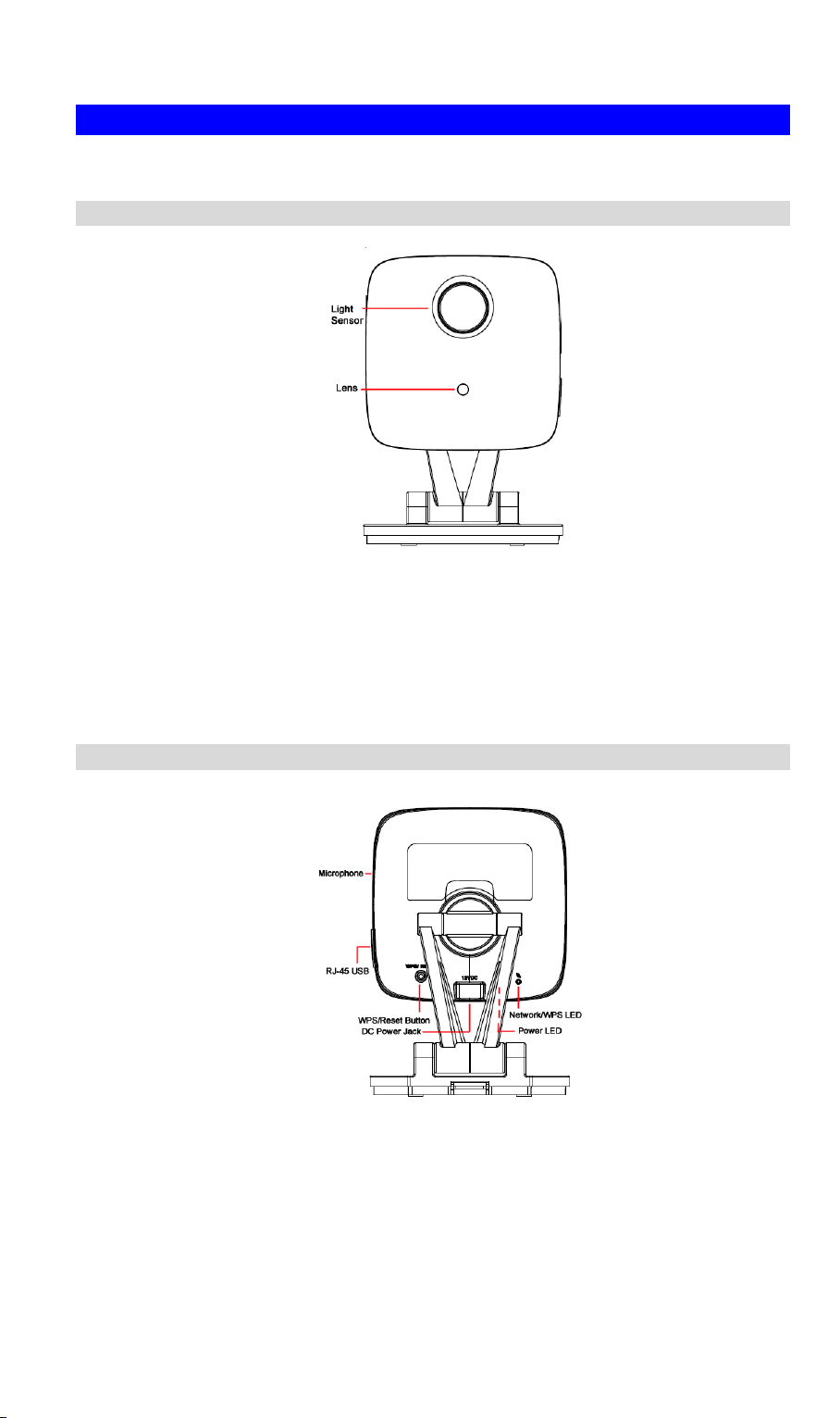
Light Sensor
This is hardware sensor to detect LUX.
Lens
No physical adjustment is required or possible for the lens, but you
should ensure that the lens cover remain clean. The image quality is
degraded if the lens cover is dirty or smudged.
Microphone
The built-in microphone is useful for bi-direction voice
conversation.
Physical Details - WiFi IP Camera
Front Panel
Figure 1: Front Panel
Rear Panel
Figure 2: Rear Panel
2
Page 7

LAN port
Use the provided RJ-45 USB cable to connect your WiFi IP Camera
to a 10/100BaseT hub or switch.
Note:
Plugging in the RJ-45 USB cable will disable the Wireless
interface. Only 1 interface can be active at any time.
The RJ-45 USB cable should only be connected or disconnected
when the camera is powered OFF. Attaching or detaching the
RJ-45 USB cable while the camera is powered on does NOT
switch the interface between wired and wireless.
WPS/Reset Button
Push the WPS button on the device and on your other wireless
device to perform WPS function that easily creates an encryptionsecured wireless connection automatically.
WPS PBC Mode. When pressed and released (less then 3
seconds), the WiFi IP Camera will be in the WPS PBC mode
(Auto link mode).
WPS Pin Code Mode. When pressed and held for over 3
seconds, the WiFi IP Camera will be in the WPS Pin Code
mode.
Reset to manufacturer default valued and reboot. When
pressed and held over 10 seconds, the settings of WiFi IP
Camera will be set to their default values.
DC Power Input
Connect the supplied 12V power adapter here. Do not use other
power adapters; doing so may damage the camera.
Power LED
Network/WPS LED
3
Page 8

Package Contents
The following items should be included in the package: If any of these items are damaged or
missing, please contact your dealer immediately.
.
4
Page 9

Mode: Infrastructure
SSID: ANY
Wireless Security: Disabled
Domain: USA
Channel No.: Auto
2
Chapter 2
Basic Setup
This Chapter provides information on how to install and configure the WiFi
IP Camera.
System Requirements
To use the Wireless interface on the wireless model, other Wireless devices must be
compliant with the IEEE802.11ac, IEEE802.11n, IEEE802.11a, IEEE802.11b or
IEEE802.11g specifications. All Wireless stations must use compatible settings.
Installation
1. Find the Location
Identify the location for the WiFi IP Camera.
2. Connect the LAN Cable
Connect the WiFi IP Camera to a 10/100BaseT hub or switch, using the supplied
RJ-45 USB cable and a standard LAN cable.
5
Page 10

For this Model, it will disable the Wireless Interface. The
Wireless and LAN interfaces cannot be used simultaneously.
Using the LAN interface is recommended for initial
configuration. After the Wireless settings are correct, the
Wireless interface can be used.
The first time you connect to the camera, you should connect
the RJ-45 USB cable and configure the WiFi IP Camera with
appropriate settings. Then you can unplug the RJ-45 USB
cable and power off the camera. The WiFi IP Camera will be in
wireless interface when you power on the camera again.
3. Power Up
Connect the supplied 12Vpower adapter to the WiFi IP Camera and power up. Use only
the power adapter provided. Using a different one may cause hardware damage.
4. Check the LEDs
The Power LED will turn on briefly, then start blinking. It will blink during startup, which
will take 55 to 57 seconds. After startup is completed, the Power LED should remain ON.
The Network/WPS LED should be ON.
6
Page 11

Wall Mounting
*Note: Please ensure that the WiFi IP Camera is configured and added to the network before
mounting it.
1. Push up to release the mounting plate from the stand
2. Identify the location for mounting the WiFi IP Camera.
3. Install and drive two screws 2/3 of the way into the wall.
4. Align the two mounting holes at the bottom of the camera stand with the two screws, and
mount the mounting plate onto the screws.
a. Mount the mounting plate with the screw first.
b. Adjust the angel by moving the opening of the wall. Install the other screw after the
adjustment.
7
Page 12

Use only the power adapter provided. Using a
different one may lead to hardware damage.
5. Attached the WiFi IP Camera to the mounting plate.
6. Connect the USB to RJ-45 cable to the USB port of the WiFi IP Camera. Then use a
standard LAN cable to connect an available port on your router.
7. Connect the power cable into the back of the camera and plug the adapter end into a power
outlet.
8. Adjust the WiFi IP Camera to a desired position and secure it firmly.
8
Page 13

Multiple Use for Wall/Ceiling Mounting
With the duo-hinge and compact design of the camera, it can offer users of added performance,
smooth operation and installation convenience. Furthermore, the extension arm and smooth
rotation can be adjusted to all angles for a dynamic point of view. Users can choose the desired
angle to fulfill their needs, no matter either in wall mounting or ceiling mounting.
Wall/Ceiling Mounting Scenario
Note: Please try the angle measurement of the camera before installation, since there are still
some limitations for wall/ceiling mounting.
9
Page 14

3
Chapter 3
Viewing Live Video
This Chapter provides basic information about viewing live video.
Overview
After finishing setup via the Windows-based Wizard, all LAN users can view live video using
Internet Explorer on Windows.
This chapter has details of viewing live video using Internet Explorer.
But many other powerful features and options are available:
The camera administrator can also adjust the Video Stream, and restrict access to the
video stream to known users by requiring viewers to supply a username and password.
To make Live Video from the camera available via the Internet, your Internet Gateway or
Router must be configured correctly.
Requirements
To view the live video stream generated by the WiFi IP Camera, you need to meet the
following requirements:
Windows XP, 32-bit Windows Vista, Windows 7/8/9.
Internet Explorer 7 or later, Firefox 3.0 or later.
Connecting to a Camera on your LAN
To establish a connection from your PC to the WiFi IP Camera:
1. Start Internet Explorer.
2. In the Address box, enter "HTTP://" and the IP Address of the WiFi IP Camera.
3. When you connect, the following screen will be displayed.
10
Page 15

Figure 3: Home Screen
4. Click View Video.
5. If the Administrator has restricted access to known users, you will then be prompted for a
username and password.
Enter the name and password assigned to you by the WiFi IP Camera administrator.
6. The first time you connect to the camera, you will be prompted to install decoders.
Choose "I accept the terms of the license agreement" and click "OK".
7. Video will start playing automatically. There may be a delay of a few seconds while the
video stream is buffered.
11
Page 16

Model
WiFi IP Camera
Dimensions
72mm (W) x 68mm (H) x 30.5mm (D) (without Stand)
Operating Temperature
0 C to 45 C
Video compression
H.264 Main Profile and MJPEG
Image resolution
1080p (1920*1080),720p (1280*720), QHD (640*360), VGA
(640*480), QVGA (320*240)
Storage Temperature
-20 C to 70 C
Network Protocols
TCP/IP, HTTP, HTTPS, DHCP, UPnP, NTP, RTP, RTCP,
RTSP, DNS
Network Interface
1 RJ-45 LAN connection for Ethernet through Micro USB to
Ethernet Cable
Wireless interface
IEEE 802.11ac/802.11n/802.11a/802.11b/802.11g compatible,
WEP 64/128 bit, WPA/WPA2 personal security support
LEDs
2
IR LEDs
2
Power Adapter
12V/1A, 100~240 VAC
A
Appendix A
Specifications
WiFi IP Camera
Regulatory Approvals
FCC Interference Statement
This equipment has been tested and found to comply with the limits for a Class B digital
device, pursuant to Part 15 of the FCC Rules. These limits are designed to provide
reasonable protection against harmful interference in a residential installation. This
equipment generates, uses and can radiate radio frequency energy and, if not installed and
used in accordance with the instructions, may cause harmful interference to radio
communications. However, there is no guarantee that interference will not occur in a
particular installation. If this equipment does cause harmful interference to radio or
television reception, which can be determined by turning the equipment off and on, the
user is encouraged to try to correct the interference by one of the following measures:
12
Page 17

Reorient or relocate the receiving antenna.
Increase the separation between the equipment and receiver.
Connect the equipment into an outlet on a circuit different from that to which the receiver
is connected.
Consult the dealer or an experienced radio/TV technician for help.
FCC Caution: Any changes or modifications not expressly approved by the party
responsible for compliance could void the user's authority to operate this equipment.
This device complies with Part 15 of the FCC Rules. Operation is subject to the following
two conditions: (1) This device may not cause harmful interference, and (2) this device
must accept any interference received, including interference that may cause undesired
operation.
IMPORTANT NOTE:
Radiation Exposure Statement:
This equipment complies with FCC radiation exposure limits set forth for an uncontrolled
environment. This equipment should be installed and operated with minimum distance
22cm between the radiator & your body.
This transmitter must not be co-located or operating in conjunction with any other antenna
or transmitter.
Country Code selection feature to be disabled for products marketed to the US/CANADA
Operation of this device is restricted to indoor use only
13
 Loading...