

Page 1
User Guide
P208
CBRS Outdoor Small Cell
Page:
1/11
User Guide
Copyright © 2017 SerComm Corporation. All Rights Reserved. SerComm Corporation reserves the right
to make changes to this document without notice. SerComm Corporation makes no warranty,
representation or guarantee regarding the suitability of its products for any particular purpose.
SerComm Corporation assumes no liability arising out of the application or use of any product or circuit.
SerComm Corporation specifically disclaims any and all liability, including without limitation
consequential or incidental damages; neither does it convey any license under its patent rights, nor the
rights of others.
Page 2

User Guide
Page:
2/11
IMPORTANT SAFETY AND INSTALLATION WARNINGS
WARNING: DO NOT ATTEMPT TO SERVICE THIS PRODUCT
YOURSELF
AS OPENING OR REMOVING COVERS MAY EXPOSE YOU TO
DANGEROUS VOLTAGES OR OTHER HAZARDS. REFER ALL
SERVICING TO QUALIFIED SERVICE PERSONNEL.
MOUNTING:
Mount this device only as described in the installation instructions, otherwise
it may fall causing serious personal injury and/or damage the device. Use
only with the brackets supplied with the device. Do not use attachments not
recommended for this device as they may cause hazards.
SERVICING:
Remove power from this device and refer servicing to qualified personnel
under the following conditions:
1. If the inside of the device has been exposed to rain or water.
2. If the device does not operate normally by following the operating
instructions. Adjust only those controls that are covered by the
operating instructions as an improper adjustment of the controls may
result in damage and will often require extensive work by a qualified
technician to restore the device to its normal operation.
3. If the device has been dropped or the chassis has been damaged.
4. If the device exhibits a distinct change in performance.
REPLACEMENT PARTS:
When replacement parts are required, be sure the service technician has
used replacement parts specified by the manufacturer or have the same
characteristics as the original part. Unauthorized substitutions may result in
f ire, electric shock or other hazards.
Page 3

User Guide
Page:
3/11
1 Product Overview
1.1 Introduction
This manual is written to help service personnel understand and install the
Sercomm P208 (P208-TP or P208-OP) Citizen Broadband Radio Service
(CBRS) outdoor Small Cell. This first section gives a full product description
and a block diagram. The remaining sections provide component
identification diagrams, installation instructions, and specifications.
1.2 General Description
This Small Cell is a PoE++ power device that receives power around 30W
from a PoE power source equipment through all four fairs of Ethernet. The
device operates at CBRS band or LTE band 48. Its operating frequency
range is from 3550MHz to 3700MHz. The device supports 2x2 MIMO and
has 6W EIRP. The antennae of device is embedded. The backhaul of the
Small Cell is Ethernet.
The device can be managed or monitored by Bluetooth or a HeMS server .
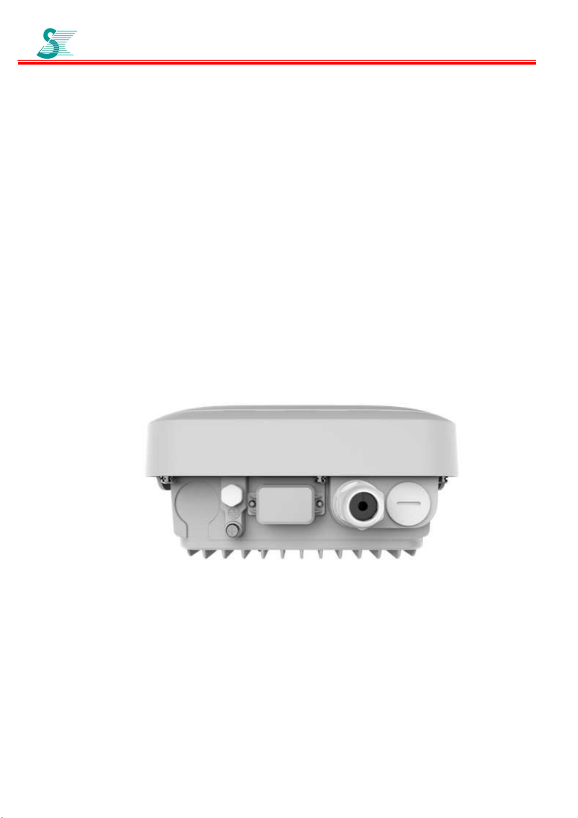
1.3 Housing
A rugged die cast aluminum on the bottom of the housing is designed. The
device has wireless antennae and aluminum or metal will block wireless
transceiver. Externally, the housing base has installation mounts, a
ventilation valve, a connector, a grounding bolt:
• A weather-tight RJ45 jack for connection from a PoE source equipment
device to provide power and backhaul to the Small Cell.
• A waterproof, dustproof ventilation valve. Its purpose is to prevent invasive
moisture, dust and other chemical crystals from entering electronics,
electrical equipment and applies the characteristic of the highly
microporous PTFE membrane to expel pressure generated by moisture
and excess heat, to avoid too large internal pressure aggregation to
damage seal housing and internal electronic components, thereby extend
the life of equipment.
The valve is setup completed before shipping. Don’t have to do anything in
Page 4

User Guide
Page:
4/11
installation for that.
• A ground bolt is to connect ground with a ground cable.
Ventilation valve
Ground bolt RJ45 Jack
1.4 Major Components
Internally, the housing bottom harbors the PCBA of the Small Cell including
bluetooth. The housing top harbors the LTE omni operating CBRS antennae
and network listening band 41 antenna.
Seal Ring
Bottom box
Shielding
Main board
Ethernet with PoE
Bluetooth
Page 5

GPS Antenna
For Pole Mount
Antenna board
User Guide
N-type Cover
Page:
GPS Antenna for Strand Antenna box
Network Listening Antenna
5/11
LTE Antenna 1
LTE Antenna 2
2 INSTALLATION
Installation of the outdoor Small Cell is similar to the installation of an outdoor WiFi AP.
2.1 Pre-Installation
Upon receipt of the CBRS Small Cell, inspect the carton for any external damage. If damage is
present inspect the Small Cell exterior for damage. Report any apparent damage to the shipping
agent and Sercomm sales office.
2.2 Power Requirements
The CBRS Small Cell needs 30W power from a PoE source equipment like a DOCSIS Gateway
through a Cat 5 cable.
Page 6

User Guide
2.3 Installation Diagrams
Strand Mount
Page:
6/11
Screw mounting kit up
to the Small Cell
Make strand through mounting kit clamps and then screw the bolts on the
clamps to lock the strand. Finally, it will look like below:
Strand Clamps
Hardline Strand
Page 7

Pole Mount
User Guide
Page:
7/11
Loose the screws to clamp the pole by re-screwing the screws.
Strand Mount with DOCSIS Gateway
Strand
Strand
Clamps
Hardline
75 ohm
Coax
DOCSIS
Small Cell
Coupler
Cat 5
Gateway
Page 8

User Guide
Page:
8/11
2.4 Installation
Installing the device requires professional training. The device must be
professionally installed by a qualified engineer familiar with system.
Failure to properly install this product may result in physical injury and/or
damage to property.
1. Before installing the device, please make sure the PoE source equipment
(like a DOSCIS gateway that provides PoE power source) has been
installed.
2. Using the diagrams in this section as guide, mount the Small Cell at its
final location.
3. Attach the shielded Ethernet outdoor CAT 5 cable from PoE source
equipment to the device as shown in section 3.5.like below diagram.
Fiexed Housing
holder
Rubber
Compression Nut
2.5 Attaching the Ethernet Cable
1. Loosen the compression nut, rubber, holder and fixed housing completely.
2. Insert the cable, with pre-installed RJ45 connector, through the nut,
rubber holder and fixed housing to the device.
3. Screw the entire compressed nut into the fixed housing, which is
already mounted on the enclosure. The rubber gasket should be
between the fixed housing and the holder. Tighten the holder and rubber to
create a seal.
Page 9

User Guide
3 Small Cell Specifications
3.1 HOUSING DIMENSIONS
Page:
9/11
Page 10

User Guide
3.2 Table of Specifications
Key Item Specification
Small Cell Type Outdoor
Working LTE Band/frequency Band48/CBRS band /3550~3700MHz
Listening bands Band 48 & Band 41
3GPP Release Release 9
TDD Configuration 1,2
Bandwidth Supported
Total Tx Output Power
Transmit dynamic range of the UUT (in EIRP,
dBm/MHz).
Transmission Mode Support TM2, TM3, TM4
MIMO 2x2 MIMO Support
5, 10, 15, 20 MHz and bandwidh of air sniffing is
EIRP Dynamic Range / MHz: [-36dbm, 30dbm]
10/11
Page:
10 or 20MHz
6W EIRP
LTE Antennae Internal Antenna
GPS antenna Internal Antenna
Active user number 64
Number of UEs in RRC Connected 96
Time Synchronization OTA, GPS & IEEE1588v2
VoLTE with QoS Support
Backhaul port 1 x Giga Ethernet
TR-69
IPSec
SSH over Public IP Address Support
SAS WINNF-TS Support
SON SuperSONTM Support
HeMS
Local wireless maintenance port Bluetooth
Input Power Requirement From PoE
Operating temperature -20oC ~ +55oC
Mount Strand mount or Pole mount
Support TR069 standard HeMS or
Sercomm’s SuperSONTM
Support
Support
Enclosure rate IP65
Physical Size
Weight Around 9.9 lbs (4.5kg)
339 x 232 x 119 mm (13.3 x 9.1 x 4.7 in)
Page 11

User Guide
Page:
11/11
Federal Communication Commission Interference Statement
This device complies with Part 15 of the FCC Rules. Operation is subject to the following two conditions: (1) This
device may not cause harmful interference, and (2) this device must accept any interference received, including
interference that may cause undesired operation.
This equipment has been tested and found to comply with the limits for a Class B digital device, pursuant to Part 15
of the FCC Rules. These limits are designed to provide reasonable protection against harmful interference in a
residential installation. This equipment generates, uses and can radiate radio frequency energy and, if not installed
and used in accordance with the instructions, may cause harmful interference to radio communications. However,
there is no guarantee that interference will not occur in a particular installation. If this equipment does cause
harmful interference to radio or television reception, which can be determined by turning the equipment off and on,
the user is encouraged to try to correct the interference by one of the following measures:
- Reorient or relocate the receiving antenna.
- Increase the separation between the equipment and receiver.
- Connect the equipment into an outlet on a circuit different from that to which the receiver is connected.
- Consult the dealer or an experienced radio/TV technician for help.
FCC Caution: Any changes or modifications not expressly approved by the party responsible for compliance could
void the user's authority to operate this equipment.
This transmitter must not be co-located or operating in conjunction with any other antenna or transmitter.
Radiation Exposure Statement:
This equipment complies with FCC radiation exposure limits set forth for an uncontrolled environment. This
equipment should be installed and operated with minimum distance 22cm between the radiator & your body.
Professional installation instruction
1. Installation personal
This product is designed for specific application and needs to be installed by a qualified personal who has RF and
related rule knowledge. The general user shall not attempt to install or change the setting.
2. Installation location
The product shall be installed at a location where the radiating antenna can be kept 22cm from nearby person in
normal operation condition to meet regulatory RF exposure requirement.
3. Installation procedure
Please refer to user’s manual for the detail.
4. Warning
Please carefully select the installation position and make sure that the final output power does not exceed the limit
set force in relevant rules. The violation of the rule could lead to serious federal penalty.
 Loading...