


Ver 1.6a
CONFIDENTIAL
Ninja LTE mini PCIe Module
LC4R-T
User Guide
Version 1.6a
This document contains information of a proprietary nature. ALL INFORMATION CONTAINED
HEREIN SHALL BE KEPT IN STRICT CONFIDENTIAL.
divulged to persons other than SerComm employees authorized by the nature of their duties to
receive information, or individuals and organizations authorized by SerComm in accordance
with existing policy regarding release of company information.
None of this information shall be
8F, No. 3-1, YuanQu St.,
Nan-Kang Taipei 115, Taiwan, R.O.C.
SerComm Corp.

CONFIDENTIAL
Change List
Revision Date Author Change descriptions
1.0 2015/10/14 Alex Tu Initial release
1.1 2015/10/14 Alex Tu Add CDD ON/OFF
1.2 2015/10/21 Alex Tu
1.3 2015/10/23 Alex Tu
1.4 2015/11/23 Alex Tu Add more AT commands
1.5 2016/4/1 Alex Tu Upgrade content update
1.6a 2016/6/6 Alex Tu Add FCC statement
Add NAS enable
Firmware upgrade
Replace 0,0,0 with null after APNNAME in AT+CGDCONT
command
2

CONFIDENTIAL
Table of Contents
Change List ................................................................................................................................................................................... 2
Table of Contents .......................................................................................................................................................................... 3
1 Product Overview ....................................................................................................................................................................... 7
1.1 Introduction ......................................................................................................................................................................... 7
1.2 System Structure ................................................................................................................................................................ 7
1.3 Network structure ................................................................................................................................................................ 8
1.4 Federal Communication Commission Interference Statement ......................................................................................... 10
Radiation Exposure Statement: .................................................................................................................................................. 10
2 DM mode.................................................................................................................................................................................. 12
2.1 Read Band Scan List ........................................................................................................................................................ 12
2.2 Write Band Scan List ........................................................................................................................................................ 12
2.3 Update Non-Volatile .......................................................................................................................................................... 12
2.4 Configure PCI Black List ................................................................................................................................................... 12
2.5 Show PCI Black List .......................................................................................................................................................... 13
3 UCFG commands .................................................................................................................................................................... 14
3.1 Connection Manager Selection ......................................................................................................................................... 14
3.2 PLMN Search Type ........................................................................................................................................................... 14
3.3 Set AutoCM Mode ............................................................................................................................................................. 14
3.4 Set ATCM Mode ............................................................................................................................................................... 15
3.5 USB Ethernet Interface Enable ......................................................................................................................................... 15
3.6 USB Ethernet Interface Disable ........................................................................................................................................ 15
3.7 USB Ethernet Interface Mode ........................................................................................................................................... 15
3.8 List of PLMN Search Type ................................................................................................................................................ 15
4 AT Commands ......................................................................................................................................................................... 16
4.1 Request information commands ....................................................................................................................................... 16
4.1.1 AT+CGMI Request manufacture identification ........................................................................................................... 16
4.1.2 AT+CGMM Request model identification ............................................................................................................... 16
4.1.3 AT+CGMR Request revision identification ................................................................................................................. 16
4.1.4 AT+CGSN Request product serial number identification ........................................................................................... 16
4.1.5 AT+CSCS Request TE character set ......................................................................................................................... 16
4.1.6 AT+CIMI Request international mobile subscriber identity .............................................................................. .......... 17
4.2 Network service related commands .................................................................................................................................. 18
4.2.1 AT+COPS PLMN selection ........................................................................................................................................ 18
3

CONFIDENTIAL
4.2.2 AT+CLCK Facility lock ................................................................................................................................................ 18
4.2.1 AT+CPWD Change password ............................................................................................................... ..................... 19
4.2.2 AT+CPOL Preferred PLMN list ................................................................................................................................... 19
4.2.3 AT+CPLS Selection of preferred PLMN list ............................................................................................................... 21
4.3 Mobile Termination control and status commands ........................................................................................................... 21
4.3.1 AT+CPAS Phone activity status ................................................................................................................................. 21
4.3.2 AT+CFUN Set phone functionality ............................................................................................................................. 22
4.3.3 AT+CPIN Enter PIN .................................................................................................................................................... 22
4.3.4 AT+CPUK Unblock PIN2 ............................................................................................................................................ 23
4.3.5 AT+CSQ Signal Quality .............................................................................................................................................. 23
4.3.6 AT+CCLK Clock ......................................................................................................................................................... 24
4.3.7 AT+CSIM Generic SIM access ................................................................................................................................... 24
4.3.8 AT+CRSM Restricted SIM access ............................................................................................................................. 25
4.3.9 AT+CLAC List all available AT commands ................................................................................................................ 26
4.3.10 AT+CPINC PIN remaining attempt number ............................................................................................................. 26
4.3.11 AT+CPINR Remaining PIN retries ........................................................................................................................... 27
4.4 Commands for packet Domain ................................................................................................ ......................................... 27
4.4.1 AT+CGDCONT Define PDP (Packet Data Protocol) Context .................................................................................... 27
4.4.2 AT+CGDSCONT Define Secondary PDP Context ..................................................................................................... 29
4.4.3 AT+CGTFT Traffic Flow Template ............................................................................................................................ 30
4.4.4 AT+CGATT PS attach or detach ................................................................................................................................ 32
4.4.5 AT+CGACT PDP Context Activate or Deactivate ..................................................................................................... 33
4.4.6 AT+CGCMOD PDP Context Modify .............................................................................................................................. 33
4.4.7 AT+CGDATA Enter data rate .................................................................................................................................... 33
4.4.8 AT+CGPADDR Show PDP (IP) address .................................................................................................................... 34
4.4.9 AT+CGEREP Packet Domain event reporting ........................................................................................................... 34
4.4.10 AT+CEREG EPS network registration status .......................................................................................................... 35
4.4.11 AT+CGCONTRDP PDP Context Read Dynamic Parameters ................................................................................ 36
4.4.12 AT+CGSCONTRDP Secondary PDP Context Read Dynamic Parameters............................................................ 37
4.4.13 AT+CGTFTRDP Traffic Flow Template Read Dynamic parameters ....................................................................... 37
4.4.14 AT+CGEQOS Define EPS Quality of Service .......................................................................................................... 39
4.4.15 AT+CGEQOSRDP EPS Quality of Service Read Dynamic Parameters .................................................................... 40
4.5 SMS Commands ............................................................................................................................................................... 41
4.5.1 AT+CSMS ...................................................................................................................................................................... 41
4.5.2 AT+CPMS ...................................................................................................................................................................... 41
4.5.3 AT+CMGF ...................................................................................................................................................................... 41
4.5.4 AT+CSCA ...................................................................................................................................................................... 41
4.5.5 AT+CSMP ...................................................................................................................................................................... 42
4

CONFIDENTIAL
4.5.6 AT+CMGL ...................................................................................................................................................................... 42
4.5.7 AT+CMGR ..................................................................................................................................................................... 44
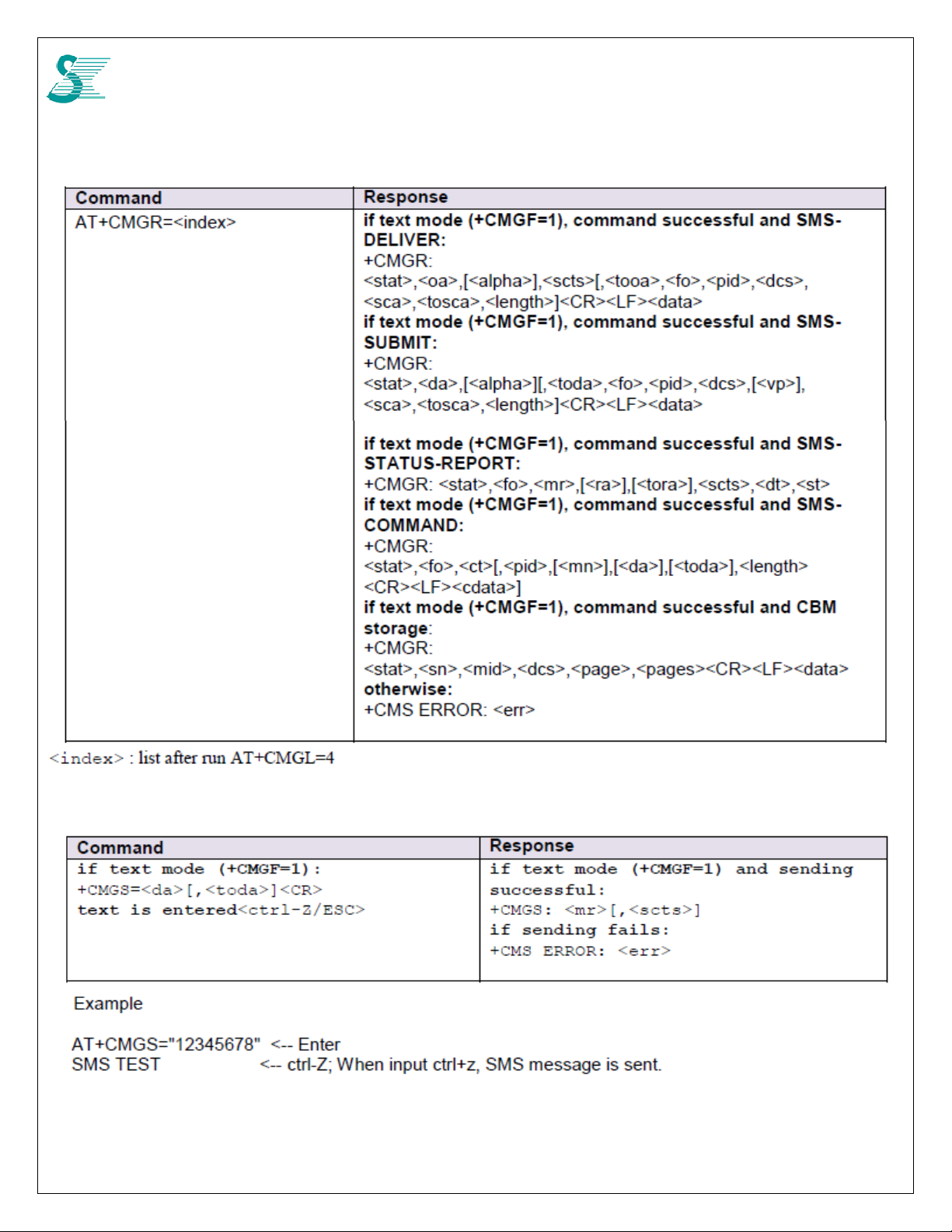
4.5.8 AT+CMGS ...................................................................................................................................................................... 44
4.5.9 AT+CMSS ...................................................................................................................................................................... 45
4.5.10 AT+CMGW ................................................................................................................................................................... 45
4.5.11 AT+CMGD ................................................................................................................................................................... 45
4.5.12 AT+CMGC ................................................................................................................................................................... 46
5 Other commands ..................................................................................................................................................................... 47
5.1 CDD .................................................................................................................................................................................. 47
5.1.1 CDD ON (2 Tx) .............................................................................................................................................................. 47
5.1.2 CDD OFF (1 Tx) ............................................................................................................................................................. 47
5.2 Q Log Message ................................................................................................................................................................. 48
5.2.1 PERF: CPU Usage Profile ............................................................................................................................................. 48
5.2.2 FRAME: LTE Radio Frame Information ......................................................................................................................... 49
5.2.3 RF: RF Metric ................................................................................................................................................................. 49
5.2.4 CHAN: Channel Information .......................................................................................................................................... 50
5.2.5 MEAS: Measurement Result of a Serving Cell .............................................................................................................. 51
5.2.6 NMEAS: Measurement Result of a Neighbor Cell ......................................................................................................... 52
5.2.7 L1D: PHY DL statistics ................................................................................................................................................... 52
5.2.8 L1U: PHY UL Statistics .................................................................................................................................................. 55
5.2.9 MCS: DL/UL MCS statistics ........................................................................................................................................... 56
5.2.10 CSI: Channel State Information ................................................................................................................................... 57
5.2.11 TP: Throughput Statistics ............................................................................................................................................ 58
5.2.12 MAC ............................................................................................................................................................................. 58
5.2.13 RLC .............................................................................................................................................................................. 58
5.2.14 DP: Data-path statistics ............................................................................................................................................... 59
5.2.15 CIP: Cipher Integrity Statistics ..................................................................................................................................... 59
5.3 NAS Protocol Binary Decode ............................................................................................................................................ 60
5.3.1 Install decoder ................................................................................................................................................................ 60
5.3.2 Copy NAS Data .............................................................................................................................................................. 60
5.3.3 Paste to Decoder ........................................................................................................................................................... 60
6 Network Connection Examples ................................................................................................................................................ 61
6.1 Auto connection (Three bands) ........................................................................................................................................ 61
6.2 Auto connection (One band, B41 for example) ................................................................................................................ 61
6.3 Manual Connection (Three bands) ................................................................................................................................... 61
6.4 Manual Connection (One band only) ................................................................................................................................ 62
6.5 Disconnect ........................................................................................................................................................................ 62
5

CONFIDENTIAL
6.6 Get IP Address .................................................................................................................................................................. 62
7 FW Upgrade ............................................................................................................................................................................. 63
7.1 Using JIG board or CPE board ......................................................................................................................................... 63
6
CONFIDENTIAL
1 Product Overview
1.1 Introduction
LC4R module uses GCT GDM7243Q chipset which is a wireless LTE FDD/TDD solution. The
chipset inside the module owns a dual core CPU. One of CPU (ARM1) is designed to run LTE
modem job; the other CPU (ARM0) is designed for router or other application.
In order to get full control, GCT designs three kinds of command sets.
AT commands : 3GPP standard compatible commands to control network connection
DM commands : GCT proprietary commands for calibration and NVM configuration
UCFG commands : GCT proprietary application that manages LTE NVM (Non-Volatile
Memory) block used as command based interface at GDM7243 Linux kernel environment.
We will use them for different purposes.
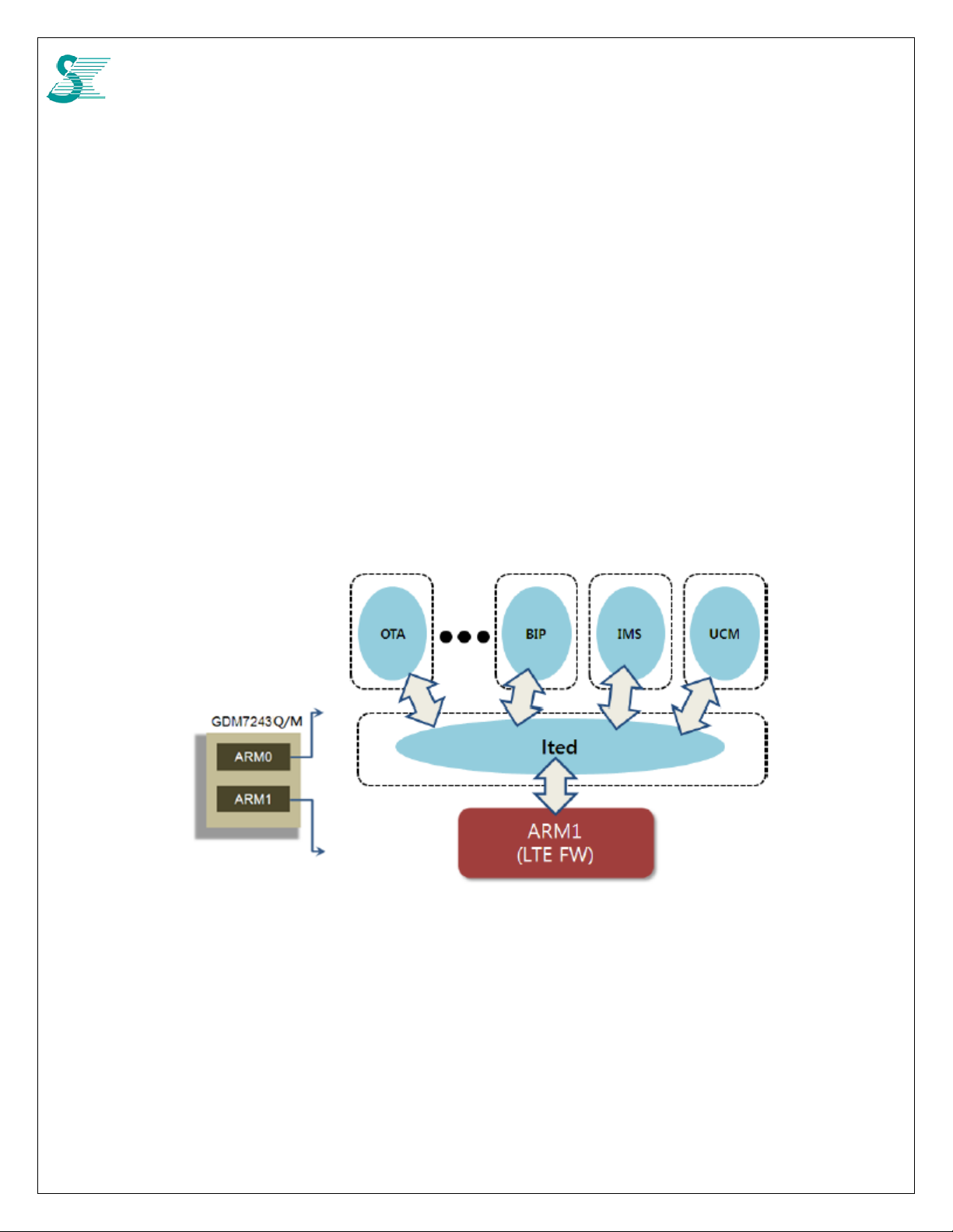
1.2 System Structure
Figure 1: Device Application for CPE
From above diagram, there is an UCM (Unify Connection Manager) application running in ARM0
for connnection function. To simply dial process, using it is good suggestion, and AT commands are
required. If more specific dial requirement required, DM/UCFG commands are needed.
7
CONFIDENTIAL
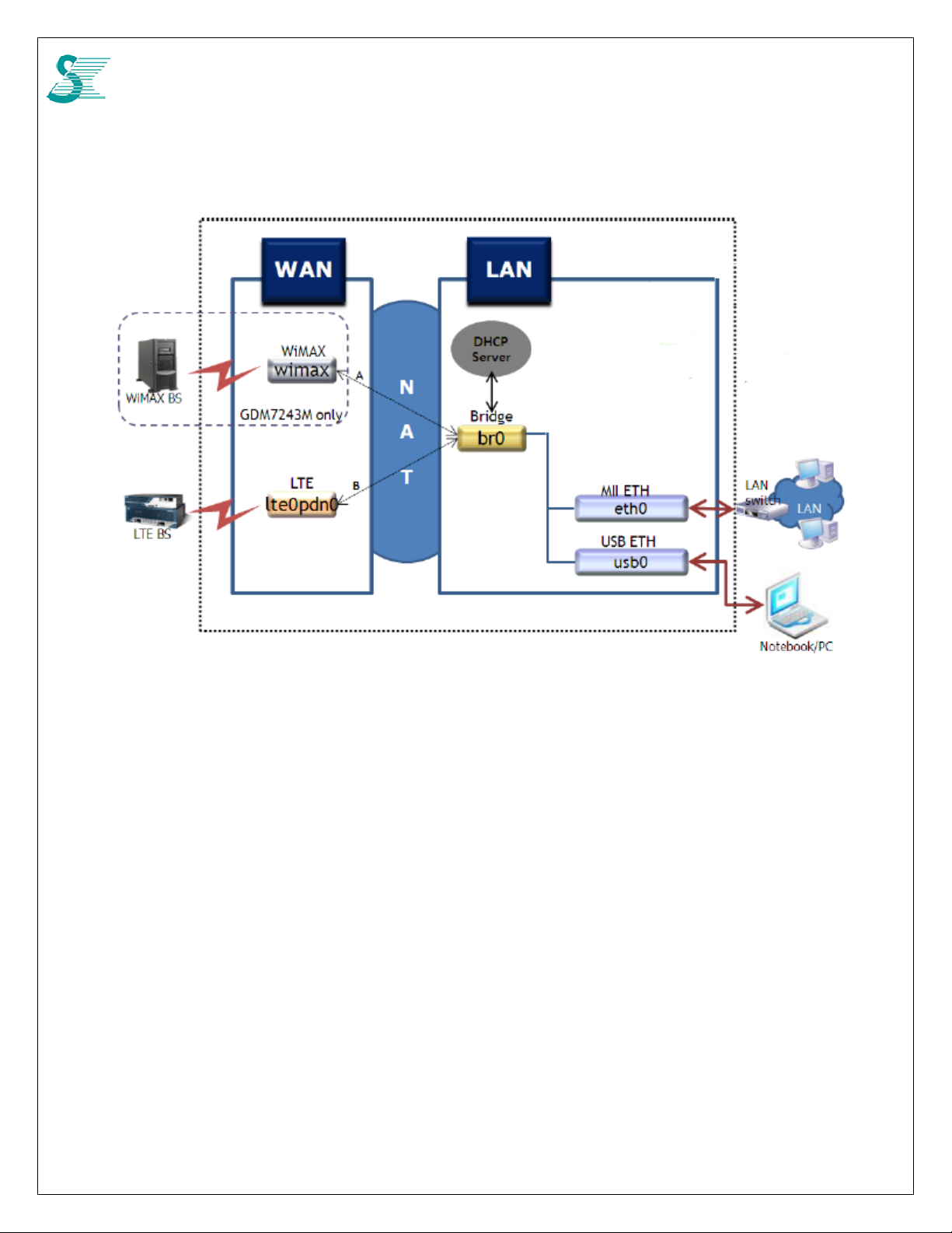
1.3 Network structure
GDM7243M network block diagram
LC4R chipset, GDM7243Q, doesn’t have WiMAX function. MII ETH is not used either due to mini
PCIe form factor, so usb0 is the only interface for network communication.
When NAT is enabled, notebook/PC will get IP from DHCP server on br0 interface, it will be like
192.168.0.10. br0 IP is 192.168.0.1. ltepdn0 IP can be retrieved by AT command or DM command Host
Interface.
LC4R uses USB 2.0 for data communication. USB interface need to be enabled and usb
mode need to be configured for different condition.
Connect to test board and Windows PC Auto or RNDIS mode
Connect to Linux OS CDC-EEM or CDC-ECM mode
ACM port is a virtual port on USB for AT command access only. We suggested using this
interface for AT command because there is no console dump data which mixes with AT
command response. Device can be found at /dev/ttyACM0.
8
CONFIDENTIAL
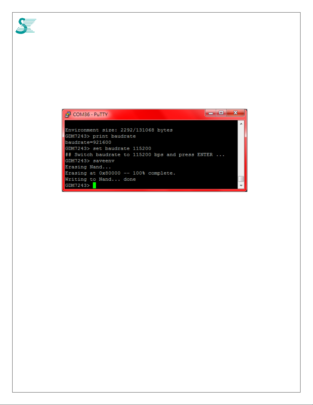
Modem control and monitor are done by UART which is defined in reserved pin 17 & 19 of
mini PCIe interface. UART0_TXD and UART0_RXD voltage is 1.8V. Default baud rate is
921600/n/8/1. If CPE board baud rate cannot support such high bit rate, reducing baud rate is
doable from UART at boot loader mode or by pre-configuration.
To update UART port baudrate, go to boot loader (reboot and press enter key during booting), and follow the
commands to update new value. Reboot is still required to take new baudrate working.
9

CONFIDENTIAL
1.4 Federal Communication Commission Interference Statement
This device complies with Part 15 of the FCC Rules. Operation is subject to the following two conditions: (1) This device
may not cause harmful interference, and (2) this device must accept any interference received, including interference
that may cause undesired operation.
This equipment has been tested and found to comply with the limits for a Class B digital device, pursuant to Part 15 of
the FCC Rules. These limits are designed to provide reasonable protection against harmf ul interference in a resid ential
installation. This equipment generates, uses and can radiate radio frequency energy and, if not installed and used in
accordance with the instructions, may cause harmful interference to radio communications. However, there is no
guarantee that interference will not occur in a particular installation. If this equipment does cause harmful interference
to radio or television reception, which can be determined by turning the equipment off and on, the user is encouraged to
try to correct the interference by one of the following measures:
Reorient or relocate the receiving antenna.
Increase the separation between the equipment and receiver.
Connect the equipment into an outlet on a circuit different from that
to which the receiver is connected.
Consult the dealer or an experienced radio/TV technician for help.
FCC Caution:
Any changes or modifications not expressly approved by the party responsible for compliance could void the
user's authority to operate this equipment.
This transmitter must not be co-located or operating in conjunction with any other antenna or transmitter.
Radiation Exposure Statement:
This equipment complies with FCC radiation exposure limits set forth for an uncontrolled environment. This equipment
should be installed and operated with minimum distance 21cm
This device is intended only for OEM integrators under the following conditions:
1) The antenna must be installed such that 21 cm is maintained between the antenna and
users, and
2) The transmitter module may not be co-located with any other transmitter or antenna.
As long as 2 conditions above are met, further transmitter
responsible for testing their end-product for any additional compliance requirements required with this module installed
IMPORTANT NOTE: In the event that these conditions can not be met
location with another transmitter), then the FCC authorization is no longer considered valid and the FCC ID can not
used on the final product. In these circumstances, the OEM integrator will be responsible for re-evaluating the end
product (including the transmitter) and obtaining a separate FCC authorization.
End Product Labeling
This transmitter module is authorized only for use in device where the antenna may be installed such that 21 cm may
be maintained between the antenna and users. The final end product must be labeled in a visible area with the
following: “Contains FCC ID: P27LC4RT1”. The grantee's FCC ID can be used only when all FCC compliance
requirements are met.
Manual Information To the End User
between the radiator & your body.
test will not be required. However, the OEM integrator is still
(for example certain laptop configurations or co-
be
10

CONFIDENTIAL
The OEM integrator has to be aware not to provide information to the end user regarding how to install or remove this
RF module in the user’s manual of the end product which integrates this module. The end user manual shall include all
required regulatory information/warning as show in this manual.
11
CONFIDENTIAL
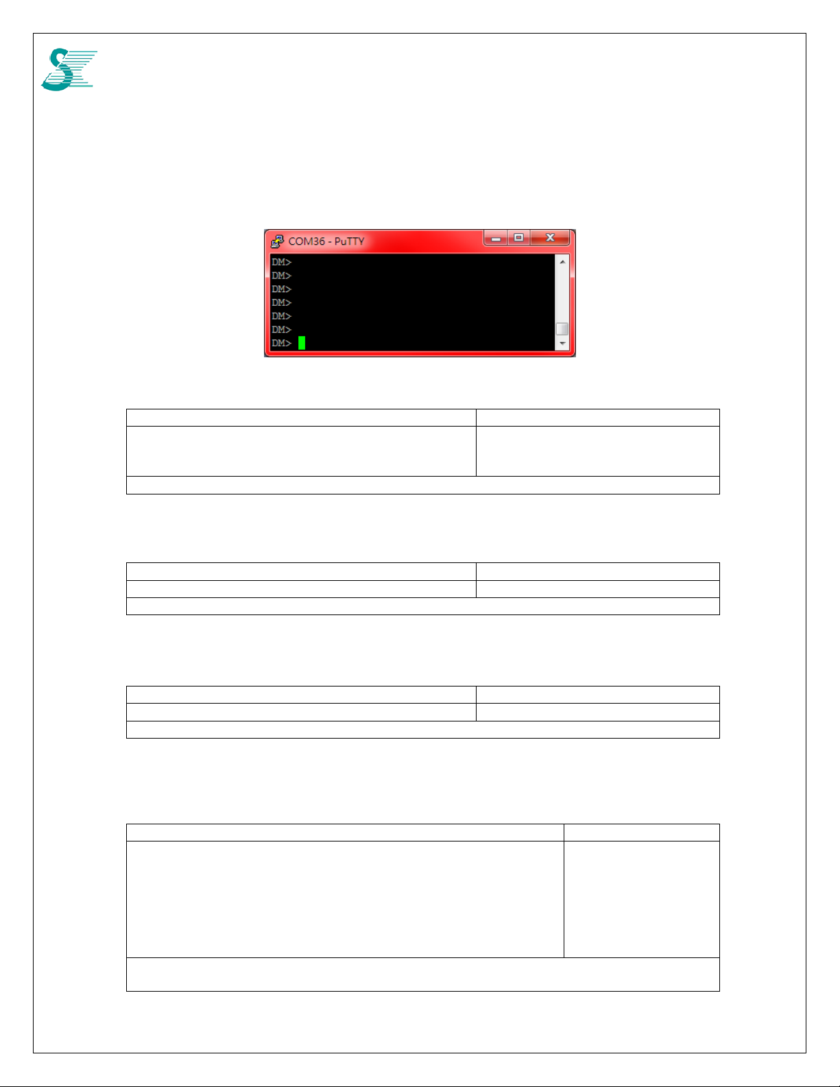
2 DM mode
When system boots up, ”DM>” prompt will be seen, then DM mode is active. Some of commands
will be introduced in the following section.
2.1 Read Band Scan List
Command Response
nv bcfgr <cmd=49> <port=0> 0 0 0 0 0 0 0 0 0 0 0 0 0 0 0 0 0 0 0
0 0 0 0 0 0 0 0 0 0 0 0 0
OK
Example: nv bcfgr 49 0
2.2 Write Band Scan List
Command Response
nv bcfgw <cmd=49> <port=0> <band=41 25 26> OK
Example: nv bcfgw 49 0 41 25 26
2.3 Update Non-Volatile
Command Response
nv bcfgsv <cmd=1> OK
Example: nv bcfgsv 1
2.4 Configure PCI Black List
This command sets cell black list.
Command Response
rrc dm cell block [[<earfcn> <pci>]]
rrc dm cell block < 'a' or 'd'> [[<earfcn> <start pci> <end pci>]]
'a' : add a cell to the list
'd' : delete a cell from the list
start pci : low PCI of the range
end pci : high PCI of the range
Notice: total 48 records
Example: rrc dm cell block a 39650 0 100
rrc dm cell block d 39650 0 100
12

CONFIDENTIAL
2.5 Show PCI Black List
Command Response
rrc dm cell block ?
Cell Black List : 2 (use SIB9:0)
>> earfcn: 39950, pci: 0 ~ 100
>> earfcn: 38950, pci: 0 ~ 100
13
CONFIDENTIAL
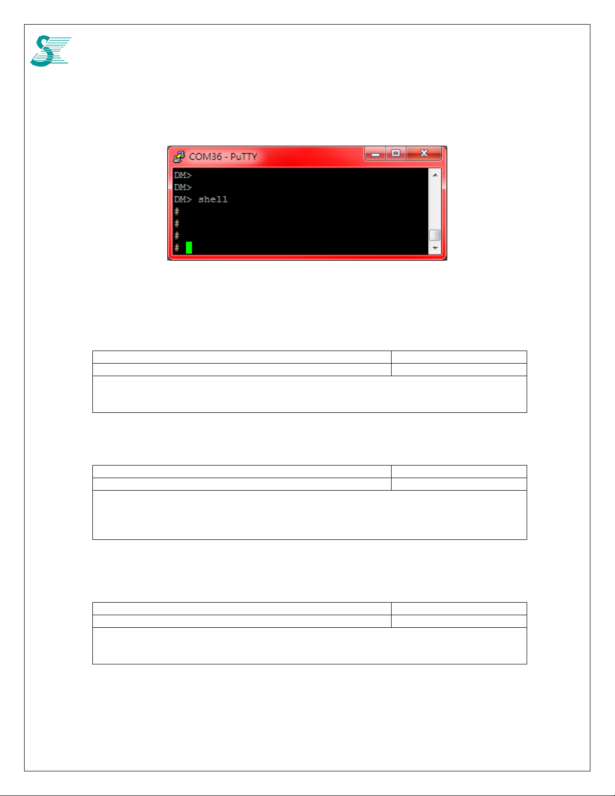
3 UCFG commands
UCFG application needs to be run at Linux kernel. To go to Linux shell, type shell from DM>,
Type “exit” to return DM> mode from Llinux shell mode
3.1 Connection Manager Selection
Command Response
ucfg set config wan lte vendor <value> vendor=<value>
<value> :
0 None
1 lteautocm
3.2 PLMN Search Type
Command Response
ucfg set config wan lte plmn_search_type <value> vendor=<value>
<value> :
0 PLMN Search
1 PLMN Search with band
2 PLMN Extension Search
3.3 Set AutoCM Mode
To set lteautocm operation mode. If manual connection is designed, manual mode of lteaucm is used
Command Response
ucfg set config wan lte autocm manual <value> vendor=<value>
<value> :
0 Auto
1 Manual
14

CONFIDENTIAL
3.4 Set ATCM Mode
To set atcm mode about PDN connect
Command Response
ucfg set config wan lte atcm use_autocm_req <value> vendor=<value>
<value> :
0 By itself
1 Request to lteautocm
3.5 USB Ethernet Interface Enable
Command Response
ucfg set config lan usbeth ENABLE 1 ENABLE=1
3.6 USB Ethernet Interface Disable
Command Response
ucfg set config lan usbeth ENABLE 0 ENABLE=0
3.7 USB Ethernet Interface Mode
Command Response
ucfg set config lan usbeth mode <value> mode=<value>
<value> :
0 Auto Detect (Default)
1 RNDIS
2 CDC-EEM
3 CDC-ECM
3.8 List of PLMN Search Type
Command Response
ucfg set plmn search_list <[type]/[number]/[value]... [type]/[number]/[value]> mode=0
[type] : the type of PLMN Search
1 MRU Search
2 Earfcn Search
3 Band Search
4 Sarfcn Range Search
[number] : the count of each PLMN Search type, Max of number is 5
While type=1, means The count of MRU Search
While type=2, means The number of earfcn
While type=3, means The number of Band
While type=4, means The number of Earfcn range
[value] : value of each PLMN Search type
1 N/A
2 /earfcn_1/earfcn_2/...../earfcn_[number]
3 /band_1/band_2..../band_[number]
4 /start_earfcn_1/end_earfcn1/...../start_earfcn_[number]/end_earfcn_[number]
15

CONFIDENTIAL
4 AT Commands
AT commands can be accessed from UART port and ACM port.
4.1 Request information commands
4.1.1 AT+CGMI Request manufacture identification
This command gets the manufacture identification
Command Response Value
+CGMI <manufacture>
+CME ERROR: <err>
+CGMI=?
GCT
4.1.2 AT+CGMM Request model identification
This command gets the model identification
Command Response Value
+CGMM <model>
+CME ERROR: <err>
+CGMM=?
- <model>: The value will be updated to GDM7243Q in next FW release.
GDM7243R0
4.1.3 AT+CGMR Request revision identification
This command gets the revision identification
Command Response Value
+CGMR <revision>
+CME ERROR: <err>
+CGMR=?
FW_VER: 0.2.65.1
4.1.4 AT+CGSN Request product serial number identification
This command gets the serial number identification
Command Response Value
+CGSN <sn> IMEI
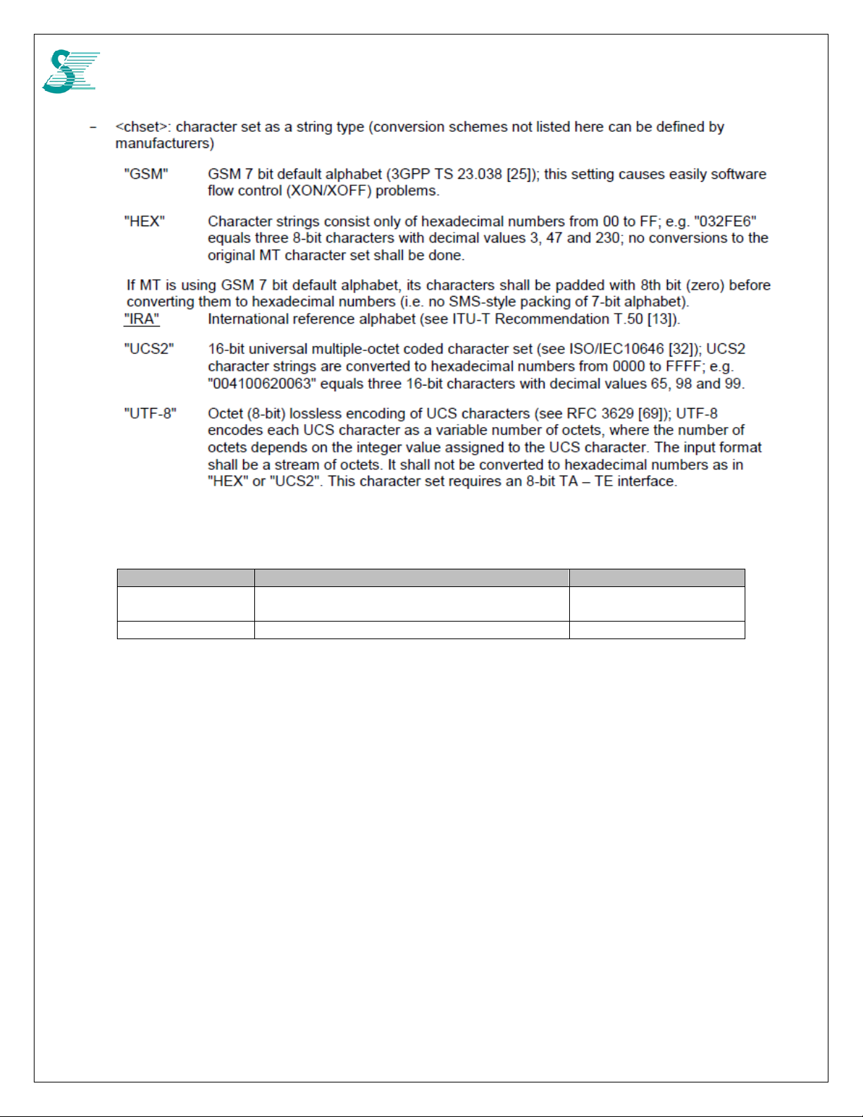
4.1.5 AT+CSCS Request TE character set
Command Response Value
+CSCS=[<chset>]
+CSCS? +CSCS:<chset>
+CSCS=? +CSCS: (list of supported <chset>s)
16
CONFIDENTIAL
4.1.6 AT+CIMI Request international mobile subscriber identity
Command Response Value
+CIMI <IMSI>
+CME ERROR: <err>
+CIMI=?
- <IMSI>: Interational Mobile Subscriber Identity (string without double quote)
17
CONFIDENTIAL
4.2 Network service related commands
4.2.1 AT+COPS PLMN selection
Forces an attemp to select and register the GSM/UMTS network operator
Command Possible Response
+COPS=? +COPS: ([list of supported<stat> ,long alphanumeric
<oper> ,short alphanumeric <oper> ,numeric
<oper>[,<Act>] )s][,,(list of supported<mode> s),(list
of supported <format> s)]
+CME ERROR:<err>
+COPS? +COPS: <mode>[,<format>,<oper>[,<Act>]]
+COPS=[<mode>[,format>[,<oper>]]]
- <stat>: Availability of operator
0 unknown
1 available
2 current
3 forbidden
- <oper>: Shows the operator identity in the format set by <format>
- <mode>: Registration mode
0 automatic (<oper> field is ignored)
1 manual (<oper> field shall be present, and <AcT> optionally)
2 deregister from network
3 set only <format> (for read command AT+COPS?), do not attempt registration / de-
registration (<oper> field is ignored); this value is not applicable in read command
response
4 manual/automatic (<oper> field shall be present); if manual selection fails, automatic
mode<mode> =0) is entered
5 manual (use plmn extension list)
- <format>: Format of <oper> reports
0 long format alphanumeric <oper>
1 short format alphanumeric <oper>
2 numeric <oper>
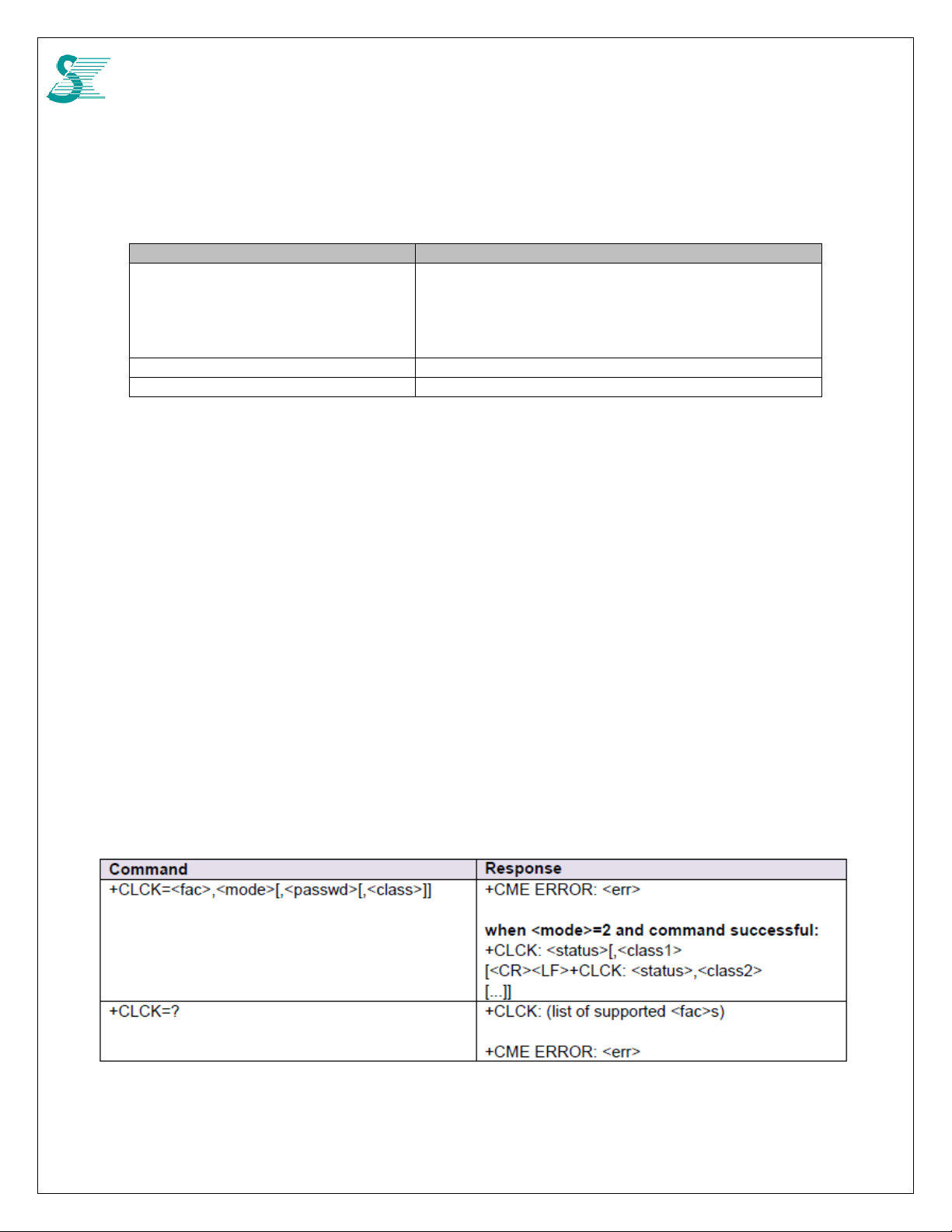
4.2.2 AT+CLCK Facility lock
18
CONFIDENTIAL
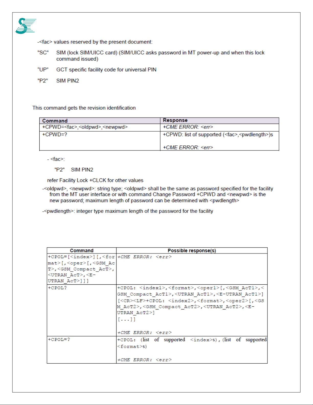
4.2.1 AT+CPWD Change password
4.2.2 AT+CPOL Preferred PLMN list
19
CONFIDENTIAL
20

CONFIDENTIAL
4.2.3 AT+CPLS Selection of preferred PLMN list
4.3 Mobile Termination control and status commands
4.3.1 AT+CPAS Phone activity status
21
CONFIDENTIAL
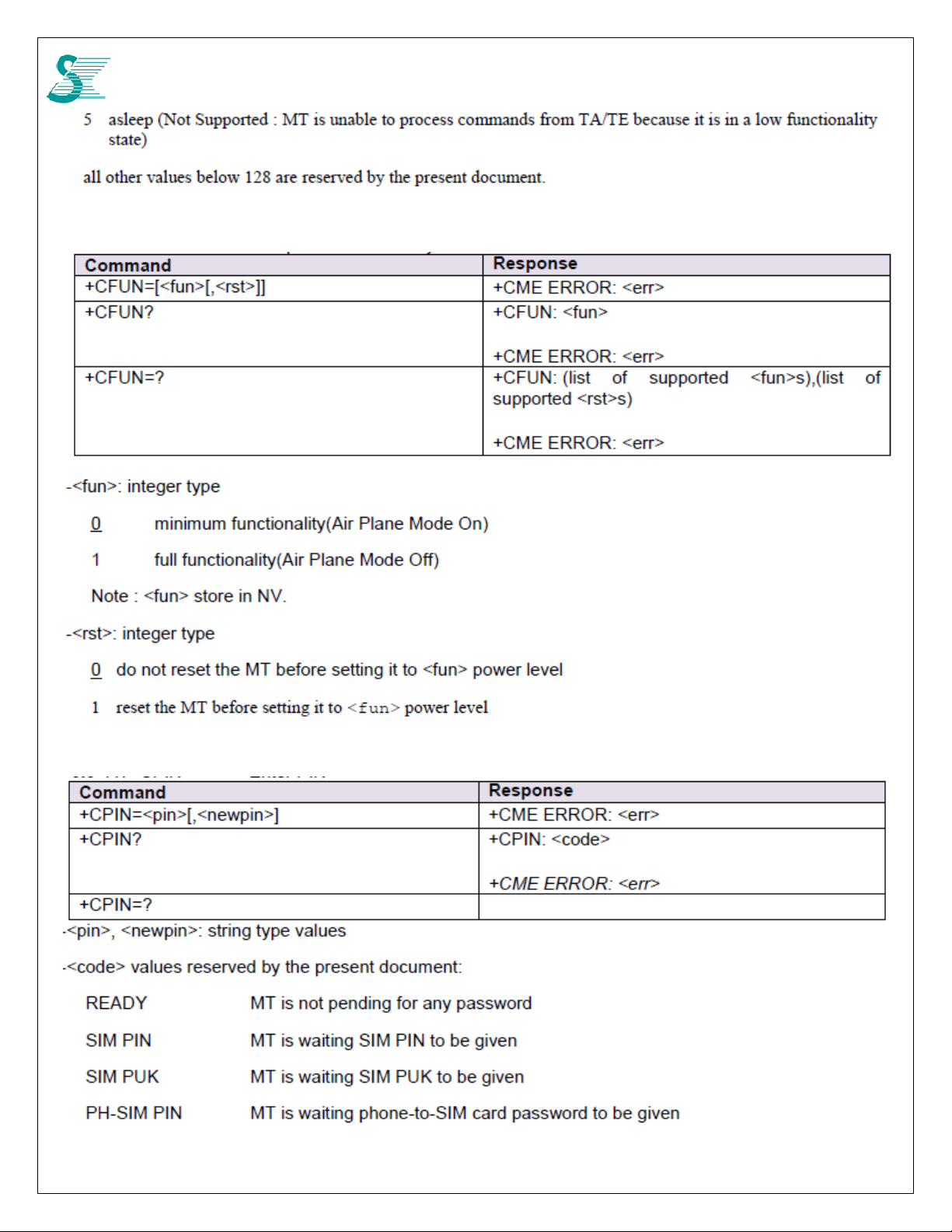
4.3.2 AT+CFUN Set phone functionality
4.3.3 AT+CPIN Enter PIN
22

CONFIDENTIAL
4.3.4 AT+CPUK Unblock PIN2
4.3.5 AT+CSQ Signal Quality
23

CONFIDENTIAL
4.3.6 AT+CCLK Clock
4.3.7 AT+CSIM Generic SIM access
24

CONFIDENTIAL
4.3.8 AT+CRSM Restricted SIM access
25

CONFIDENTIAL
4.3.9 AT+CLAC List all available AT commands
4.3.10 AT+CPINC PIN remaining attempt number
26

CONFIDENTIAL
4.3.11 AT+CPINR Remaining PIN retries
4.4 Commands for packet Domain
4.4.1 AT+CGDCONT Define PDP (Packet Data Protocol) Context
Specifies PDP context parameter values for a PDP context identified by the (local) context
identification parameter, <cid>.
- [set command]
: specifies PDP context parameter values for a PDP context identified by the (local) context
identification parameter, <cid>.
: a special form of the set command, +CGDCONT=<cid> causes the values for context
number <cid> to become undefined.
- [read command]
: returns the current settings for each defined context.
- [test command]
: returns values supported as a compound value.
Command Response
+CGDCONT=[<cid>[,<PDP_type>[,<APN>[,
<PD
P_addr>[,<d_comp>[,<h_comp>[,<IPv4Addr
A
lloc>[,<emergency indication>[,<PCSCF_
discovery>[,<IM_CN_Signalling_Flag
_Ind>]]]]]]]]]]
+CGDCONT? +CGDCONT: <cid>,<PDP_type>, <A PN>,<PDP_ad
OK
ERROR
dr>,<d_comp>,<h_comp>[,<IPv4AddrAlloc>[,<emerg
27

CONFIDENTIAL
ency indication>[,<PCSCF_
discovery>[,<IM_CN_Signalling_Flag_
Ind>]]]][<CR><LF>+CGDCONT:
<cid>,<PDP_type>,<APN>,<PDP_addr>,<d_comp>,
<h_comp>[,<IPv4Add
rAlloc>[,<emergency indication>[,<PCSCF_
discovery>[,<IM_CN_Signalling_Flag_
Ind>]]]][...]]
+CGDCONT=? +CGDCONT: (range of supported
<cid>s),<PDP_type>,,,(list of supported
<d_comp>s),(list of supported <h_comp>s),(list of
supported <IPv4AddrAlloc>s),(list of supported
<emergency indication>s),(list of supported <PCSCF_
discovery>s),(list of supported
<IM_CN_Signalling_Flag_Ind>s)
[<CR><LF>+CGDCONT: (range of supported
<cid>s),<PDP_type>,,,(list of supported
<d_comp>s),(list of supported <h_comp>s),(list of
supported <IPv4AddrAlloc>s),(list of supported
<emergency indication>s),(list of supported <PCSCF_
discovery>s),(list of supported
<IM_CN_Signalling_Flag_Ind>s)
[...]]
- <cid>: numeric; specifies a particular PDP context definition.
- <PDP_type>: string; specifies the type of packet data protocol
X.25 : ITU-T/CCITT X.25 layer 3 (Obsolete)
IP : Internet Protocol
IPV6 : Internet Protocol, version 6
IPV4V6 : Virtual <PDP_type> introduced to handle dual IP stack UE capability.
OSPIH : Internet Hosted Octect Stream Protocol (Obsolete)
PPP : Point to Point Protocol (IETF STD 51)
- <APN>: string; a logical name that is used to select the GGSN or the external packet data network
- <PDP_addr> for EPS, this field is omitted.
- <d_comp>: numeric; controls PDP data compression.
0 - off (default if value is omitted)
1 - on (manufacturer preferred compression)
2 - V.42bis
3 - V.44
Other values are reserved.
- <h_comp>: numeric; controls PDP header compression.
0 - off (default if value is omitted)
1 – on (manufacturer preferred compression)
2 - RFC1144 (applicable for SNDCP only)
3 - RFC2507
4 - RFC3095 (applicable for PDCP only)
Other values are reserved.
- <IPv4AddrAlloc>: numeric; controls how the MT/TA requests to get the IPv4 address information
0 - IPv4 Address Allocation through NAS Signaling (default if omitted)
1 - IPv4 Address Allocated through DHCP
- <emergency indication>: a numeric parameter used to indicate whether the PDP context is for emergency bearer
services or not.
0 PDP context is not for emergency bearer services
- <P-CSCF_discovery>: a numeric parameter influences how the MT/TA requests to get the P-CSCF address, see
3GPP TS 24.229 [89] annex B and annex L.
0 Preference of P-CSCF address discovery not influenced by +CGDCONT
1 Preference of P-CSCF address discovery through NAS Signalling
28
CONFIDENTIAL
2 Preference of P-CSCF address discovery through DHCP
- <IM_CN_Signalling_Flag_Ind>: a numeric parameter used to indicate to the network whether the PDP context is for
IM CN subsystem-related signalling only or not.
0 UE indicates that the PDP context is not for IM CN subsystem-related signalling only
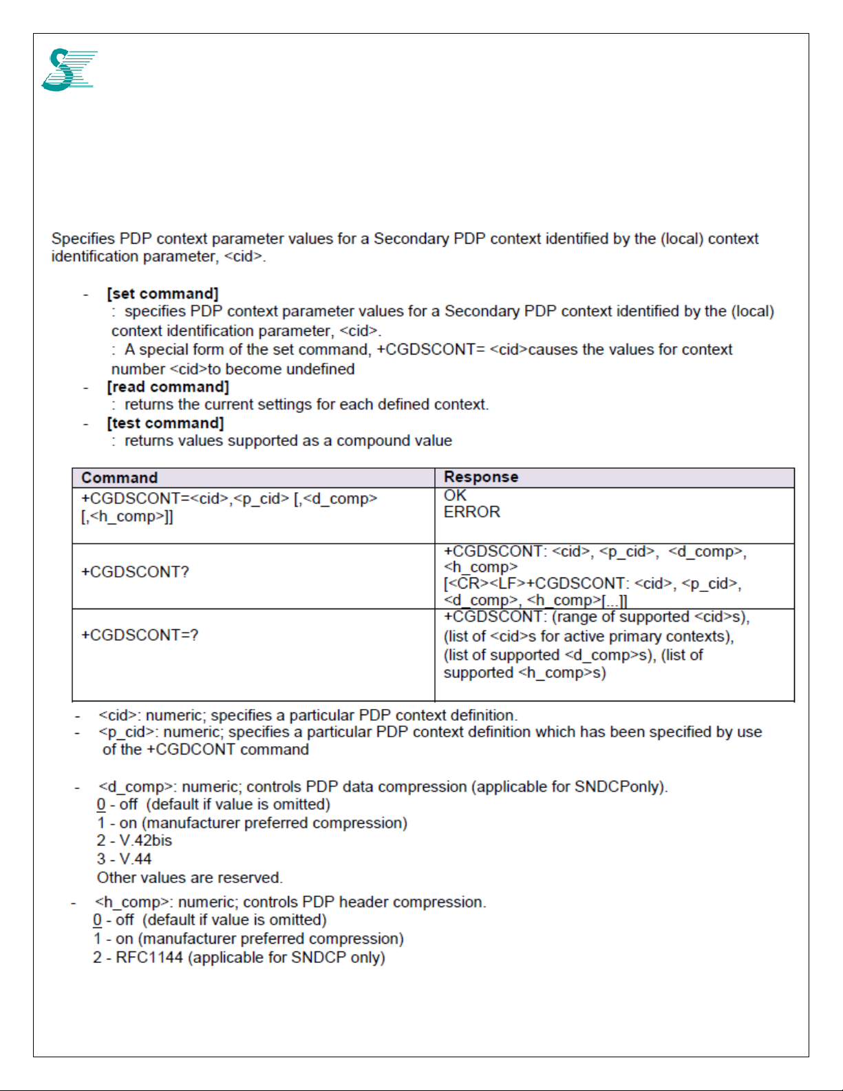
4.4.2 AT+CGDSCONT Define Secondar y PDP Context
29

CONFIDENTIAL
4.4.3 AT+CGTFT Traffic Flow Template
30

CONFIDENTIAL
31

CONFIDENTIAL
4.4.4 AT+CGATT PS attach or detach
32

CONFIDENTIAL
4.4.5 AT+CGACT PDP Context Activate or Deactivate
Activate or deactivate the specified PDP context(s).
- [execution command]
: activate or deactivate the specified PDP context(s). <cid>: is a numeric parameter which specifies a
particular PDP context definition.
- [read command]
: returns the current Packet Domain service state.
- [test command]
: requests information on the supported PDP context activation states
Command Response
+CGACT=<state>,<cid> OK
ERROR
+CGACT? +CGACT: <cid>, <state> [<CR><LF>+CGACT:
<cid>,
<state>[…]]
+CGACT=? +CGACT: (list of supported <state>s)
- <state>: indicates the state of PS attachment
0 – deactivated
1 – activated
other values are reserved and will result in an ERROR response to the execution command
- <cid>: numeric; specifies a particular PDP context definition.
4.4.6 AT+CGCMOD PDP Context Modify
4.4.7 AT+CGDATA Enter data rate
33

CONFIDENTIAL
4.4.8 AT+CGPADDR Show PDP (IP) address
4.4.9 AT+CGEREP Packet Domain event reporting
34

CONFIDENTIAL
4.4.10 AT+CEREG EPS network registration status
Reports changes in network registration
- [set command]
: controls the presentation of an unsolicited result code when there is a change in the MT's EPS network
registration status.
- [read command]
: returns the status of result code presentation and an integer <stat> which shows whether the network has
currently indicated the registration of the MT
- [test command]
: list of supported <n>s
Command Response
+CEREG=<n> OK
ERROR
+CEREG? +CEREG: <n>,<stat>[,<lac>,<rac>,<ci>[,<AcT>]]
+CME ERROR: <err>
+CEREG=? +CEREG: (list of supported <n>s)
-<n>: numeric;
0 disable network registration unsolicited result code
1 enable network registration unsolicited result code +CEREG: <stat>
2 enable network registration and location information unsolicited re sult code +CEREG:
<stat>[,<lac>,<rac>,<ci>[,<AcT>]]
-<stat>: numeric; EPS registration status
0 not registered, MT is not currently searching an operator to register to
1 registered, home network
2 not registered, but MT is currently trying to attach or searching an operator to register to
3 registration denied
4 unknown
5 registered, roaming
-<lac>: string; two byte location area code or tracking area code in hexadecimal format (e.g. "00C3" equals 195 in
decimal).
-<rac>: string; one byte routing area code in hexadecimal format (e.g. "1C" equals 28 in decimal). If no routing area
code is applicable, "00" (equals 00 in decimal) is provided.
-<ci>: string; four byte GERAN/UTRAN/E-UTRAN cell ID in hexadecimal format.
-<AcT>: numeric; access technology of the registered netwo rk
35

CONFIDENTIAL
0 GSM
1 GSM Compact
2 UTRAN
3 GSM w/EGPRS
4 UTRAN w/HSDPA
5 UTRAN w/HSUPA
6 UTRAN w/HSDPA and HSUPA
7 E-UTRAN
4.4.11 AT+CGCONTRDP PDP Context Read Dynamic Parameters
- [execution command]
: returns the relevant information <bearer_id>, <apn>, <ip_addr>, <subnet_mask>, <gw_ad dr>,
<DNS_prim_addr>, <DNS_sec_addr>, <P-CSCF_prim_addr> and <PCSCF_se c_addr> for a non secondary PDP
Context established by the network with the primary context identifier <p_cid>
: If the parameter <p_cid> is omitted, the relevant information for all established PDP contexts are returned
- [test command]
: returns a list of <p_cid>s associated with active contexts
Command Response
+CGCONTRDP=[<p_cid>] +CGCONTRDP: <p_cid>, <bearer_i d>, <apn>[,
<ip_addr>, <subnet_mask>[, <gw_addr>[,
<DNS_prim_addr>[, <DNS_sec_addr>[,
<PCSCF_
prim_addr>[, <P-CSCF_sec_addr>]]]]]]
[<CR><LF>+CGCONTRDP: <p_cid>,
<bearer_id>,
<apn>[, <ip_addr>, <subnet_mask>[,
<gw_addr>[,
<DNS_prim_addr>[, <DNS_sec_addr>[,
<PCSCF_
prim_addr>[, <P-CSCF_sec_addr>]]]]]]
[…]]
+CGCONTRDP=? +CGCONTRDP: (list of <p_cid>s associated
- <p_cid>: numeric; specifies a particular non secondary PDP context definition. The parameter is local to the TE-MT
interface and is used in other PDP context-related commands.
- <bearer_id>: numeric; identifies the bearer, EPS Bearer in EPS and NSAPI in UMTS/GPRS.
- <APN>: string; a logical name that was used to select the GGSN or the external packet data network.
- <ip_addr>: string; shows the IP Address of the MT. The string is given as dot-separated numeric (0-25 5) parameters
on the form:
"a1.a2.a3.a4" for IPv4 or
"a1.a2.a3.a4.a5.a6.a7.a8", for IPv6.
If the MT has dual stack capabilities the string shows first the dot separated IPv4 Address
followed by the dot separated IPv6 Global Prefix Address. The IPv4 address and the IPv6
address parameters are separated by space:
"a1.a2.a3.a4 a1:a2:a3:a4:a5:a6:a7:a8"
- <subnet_mask>: string; shows the subnet mask for the IP Address of the MT. The string is given as dot-separated
numeric (0-255) parameters.
If the MT has dual stack capabilities the string shows the dot separated IPV4 subnet mask
followed by the dot separated IPV6 subnet mask. The subnet masks are separated by space.
- <gw_addr>: string; shows the Gateway Address of the MT. The string is given as dot-separated
numeric (0-255) parameters
If the MT has dual stack capabilities the parameter shows first the dot separated IPV4 Gateway
address followed by the dot separated IPV6 Gateway Address. The gateway addresse s are
separated by space.
36

CONFIDENTIAL
- <DNS_prim_addr>: string; shows the IP Address of the primary DNS Server. If the MT has dual
stack capabilities the parameter shows first the dot separated IPV4 Address, followed by the dot
separated IPV6 Address of DNS Server.
- <DNS_sec_addr>: string; shows the IP address of the secondary DNS Server. If the MT has dual
stack capabilities the parameter shows first the dot separated IPV4 Address, followed by the dot
separated IPV6 Address of DNS Server.
- <P_CSCF_prim_addr>: string; shows the IP Address of the primary P-CSCF Server. If the MT
has dual stack capabilities the parameter shows first the dot separated IPV4 Address, followed
by the dot separated IPV6 primary Address of P-CSCF Server.
- <P_CSCF_sec_addr>: string; shows the IP Address of the secondary P-CSCF Server. If the MT has
dual stack capabilities the parameter shows first the dot separated IPV4 Address, followed by
the dot separated IPV6 Address of P-CSCF Server.
4.4.12 AT+CGSCONTRDP Secondary PDP Context Read Dynamic Parameters
4.4.13 AT+CGTFTRDP Traffic Flow Template Read Dynamic parameters
37

CONFIDENTIAL
38

CONFIDENTIAL
4.4.14 AT+CGEQOS Define EPS Quality of Service
39

CONFIDENTIAL
4.4.15 AT+CGEQOSRDP EPS Quality of Service Read Dynamic Parameters
40
CONFIDENTIAL
4.5 SMS Commands
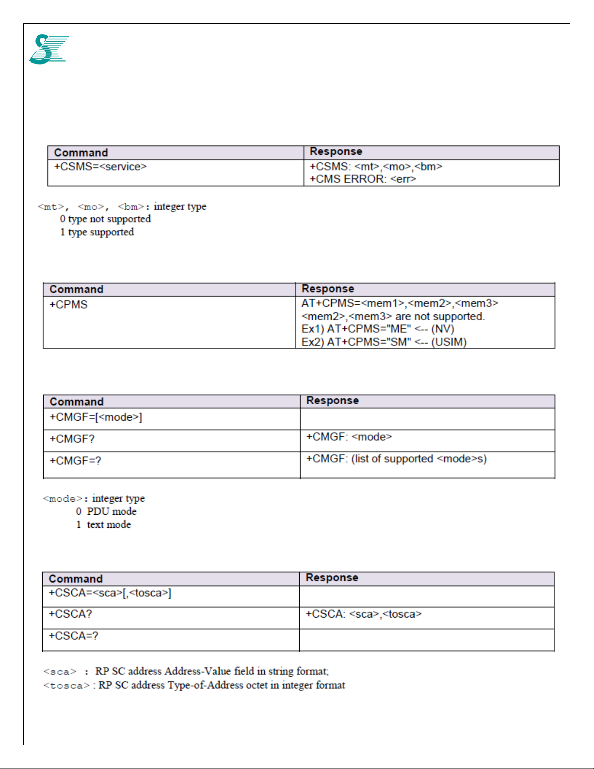
4.5.1 AT+CSMS
4.5.2 AT+CPMS
4.5.3 AT+CMGF
4.5.4 AT+CSCA
41

CONFIDENTIAL
4.5.5 AT+CSMP
4.5.6 AT+CMGL
42

CONFIDENTIAL
43
CONFIDENTIAL
4.5.7 AT+CMGR
4.5.8 AT+CMGS
44

CONFIDENTIAL
4.5.9 AT+CMSS
4.5.10 AT+CMGW
4.5.11 AT+CMGD
45

CONFIDENTIAL
4.5.12 AT+CMGC
46

CONFIDENTIAL
5 Other commands
5.1 CDD
5.1.1 CDD ON (2 Tx)
1. Run the command in shell mode,
2.Edit script file,
Update mode, chmod +x /etc/sysconfig/script/lte_init_script.sh
3.
vi etc/sysconfig/script/lte_init_script.sh
mount -o remount,rw /
4. write "
l1u t cdd 1 4" , save file, and reboot
5.1.2 CDD OFF (1 Tx)
Update etc/sysconfig/script/lte_init_script.sh with "l1u t cdd 0 4" and save file, reboot.
47

CONFIDENTIAL
5.2 Q Log Message
There are three text-DM modes when q log command uses, DM>q 0/1/2.
Interactive mode (q 0) Logging is disabled but command line interface is enabled.
Logging mode (q 1) Logging is enabled but command line interface is disabled.
Verbose mode (q 2) Both logging and CLI are enabled.
To enable NAS protocol dump, type DM>dbg nas* -1 before q log command.
5.2.1 PERF: CPU Usage Profile
Example: PERF : C(88.4/0.9/7.4/3.3) I(4101) M(H:10.0/2MB P:0.4/0.5/0.1/0.1/2MB)
48

CONFIDENTIAL
5.2.2 FRAME: LTE Radio Frame Information
Example: FRAME: CONNECTED CAT5 TDD(2:7,N) Pos=(38245,3824 7,38247,38247) STI=836
5.2.3 RF: RF Metric
49

CONFIDENTIAL
Example: RF : E(39850,39850) B41 F25160 AFC(R,0:-182:34,-160,H,0x409)
AGC(N,0x53:50:55,0x5f:5a:61,0x60:5d:61,0x6b:66:6d) ACI=0
5.2.4 CHAN: Channel Information
50

CONFIDENTIAL
Example: CHAN : 20MHz #A2 TM2 PCI=501 DS(S,96,0,0,0/0.3,0.3) ACE(I) FIB(-1:0:0:-1) CS(17:17:17:16)
5.2.5 MEAS: Measurement Result of a Serving Cell
Example: MEAS : CINR(32.1,33.6) RSRP(-75.2,-81.3) RSSI(-49.3,-55.5) RSRQ(-5.9,-5.8)
CINR(33.9,32.2) RSRP(-80.2,-87.3) RSSI(-54.3,-61.5) RSRQ(-5.9,-5.8)
51

CONFIDENTIAL
5.2.6 NMEAS: Measurement Result of a Neighbor Cell
Example: NMEAS: {39850,501,-75.0,-6.0}
5.2.7 L1D: PHY DL statistics
52

CONFIDENTIAL
53

CONFIDENTIAL
Example: L1D : DCI0=3 DCI={1A(0/3)}{} BLER(0/3,0/0) Dup(0,0) HI(0/4) CFI(796:3:1:0) TB(0,0) TP=1K
Layer-Map={1C1L=3,1C2L=0,2C2L=0,2C3L=0,2C4L=0}
54

CONFIDENTIAL
5.2.8 L1U: PHY UL Statistics
55

CONFIDENTIAL
Example: L1U : PUSCH(4)={2(0/3),7(0/1)} PRACH=1 ACK(0/3,0/0) DTX(9,12) PWR(-54.0,-23.3,-48.0,-,-28.1)
5.2.9 MCS: DL/UL MCS statistics
Example: MCS : DL={0(0/2),5(0/1)} UL={8(0/4)} PMCH={}
56

CONFIDENTIAL
5.2.10 CSI: Channel State Information
Example: CSI : RM(0,10,0,0) A30(0/0/0) P10(10/10/10) RI(0,0,0,0) PMI={}
CQI={15(10)}{}
57
CONFIDENTIAL
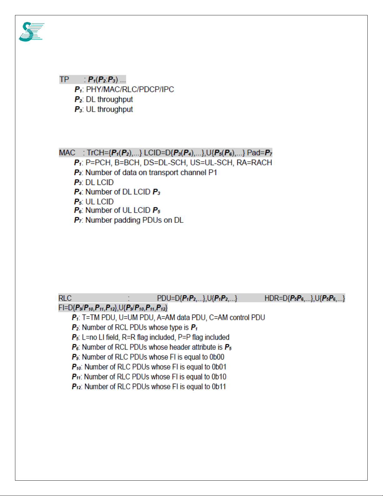
5.2.11 TP: Throughput Statistics
Example: TP : PHY(1K:1K) MAC(1K:1K) RLC(84:79) PDCP(75:73) DIM() IPC(0:0)
5.2.12 MAC
Example: MAC : [S] PDU=D{4},U{3}, CE=D{CR1,PAD(0/3)},U{PHR2,BSR(0/3/1),SR(0/2),PAD(0/3)}, I{0,0,0}
[S:0] PDU=D{1},U{2}
[S:1] PDU=D{2},U{3}
[R] RA{0/1}, CE{0,1}, CR{0,0,0}
5.2.13 RLC
Example: RLC : [0] PDU=D{T1},U{T1}
[1] PDU=D{A1,C1},U{A0/2,C1}, I{0,0,1,0}, STATE=D{1,1},U{2,2}
58

CONFIDENTIAL
5.2.14 DP: Data-path statistics
Example: DP : RLC=D0{DC0,AF0,UF0} IPC=D{F0,M0,T0},U{A0,M0,T0}
5.2.15 CIP: Cipher Integrity Statistics
Example: CIP : S=0 DL(0,0) UL(0,0) DI(0,0,0) DO(0,0,0) UI(0,0,0) UO(0,0,0) B(0)
59

CONFIDENTIAL
5.3 NAS Protocol Binary Decode
5.3.1 Install decoder
Install 3GPP message decoder
5.3.2 Copy NAS Data
Copy NAS protocol binary string
5.3.3 Paste to Decoder
60

CONFIDENTIAL
6 Network Connection Examples
6.1 Auto connection (Three bands)
Step command Description
1 DM> nv bcfgw 49 0 41 25 26 Write band number into scan list
2 DM> nv bcfgsv 1 Write NVRAM back to flash
3 DM>shell Enter shell mode
4 #ucfg set config wan lte vendor 1 Connection manager, lteautocm
5 #ucfg set config wan lte autocm manual 0 Lteautocm chooses Auto mode
6 #ucfg set config wan lte atcm use_autocm_req 1 Request to lteautocm
7 #ucfg set config wan lte apntable apn3 ENABLE 1 Enable APN3
8 #ucfg set config wan lte apntable apn3 apn_name <new_APN> Update correct APN, default is
internet
9 #reboot
6.2 Auto connection (One band, B41 for example)
Step command Description
1 DM> nv bcfgw 49 0 41 Write band number 41
2 DM> nv bcfgsv 1 Write NVRAM back to flash
3 DM>shell Enter shell mode
4 #ucfg set config wan lte vendor 1 Connection manager, lteautocm
5 #ucfg set config wan lte autocm manual 0 Lteautocm chooses Auto mode
6 #ucfg set config wan lte atcm use_autocm_req 1 Request to lteautocm
7 #ucfg set config wan lte apntable apn3 ENABLE 1 Enable APN3
8 #ucfg set config wan lte apntable apn3 apn_name <new_APN> Update correct APN, default is
9 #reboot
6.3 Manual Connection (Three bands)
Step 1 is to configure required information
Step command Description
1 DM> nv bcfgw 49 0 41 25 26 Write band number into scan list
2 DM> nv bcfgsv 1 Write NVRAM back to flash
3 DM>shell Enter shell mode
4 #ucfg set config wan lte vendor 0 Connection manager, None
5 #ucfg set config wan lte atcm use_autocm_req 0 By itself
6 #ucfg set config wan lte plmn_search_type 2 Search with extension mode
7 #ucfg set plmn search_list 3/3/41/25/26 Assign sca n band to sca n list
8 #reboot
internet
61

CONFIDENTIAL
Step 2 is using AT commands to enable modem dial up action
Step command Description
1
2
3
4
DM>AT+CGDCONT=1,"IPV4V6","APNNAME","",,,
DM>AT%GPDNTYPE=1,3 Choose APN 3 for internet
DM>AT+COPS=5
DM>AT+CGACT=1,1
APNNAME need to change to
your network internet APN
name, like ”internet”
Choose search extension
mode
Attached to network
6.4 Manual Connection (One band only)
Step 1 is to configure required information
Step command Description
1 DM> nv bcfgw 49 0 41 Write band number B41 into
scan list
2 DM> nv bcfgsv 1 Write NVRAM back to flash
3 DM>shell Enter shell mode
4 #ucfg set config wan lte vendor 0 Connection manager, None
5 #ucfg set config wan lte atcm use_autocm_req 0 By itself
6 #ucfg set config wan lte plmn_search_type 2 Search with extension mode
7 #ucfg set plmn search_list 3/1/41 Assign scan band to scan list
8 #reboot
Step 2 is using AT commands to enable modem dial up action
Step command Description
1
2 DM>AT%GPDNTYPE=1,3 Choose APN 3 for internet
3 DM>AT+COPS=5 Choose search extension
4 DM>AT+CGACT=1,1 Attached to network
DM>AT+CGDCONT=
1,"IPV4V6","APNNAME","",,,
APNNAME need to change to
your network internet APN
name, like ”internet”
mode
6.5 Disconnect
Step command Description
1 DM>AT+CGACT=0,1 Deactivate ”1” PDP context
6.6 Get IP Address
Step command Description
1 AT+CGCONTRDP=3? Cid=3
Response: AT+CGCONTRDP:
3,6,"internet.lguplus.co.kr","10.118.177.89","10.0.0.166","211.40.215.140","117.111.29.4","","",0
OK
Note: ipaddr:10.118.177.879, gateway:10.0.0.166, dns1:211.40.215.140, dns2:117.11 1.29.4
62

CONFIDENTIAL
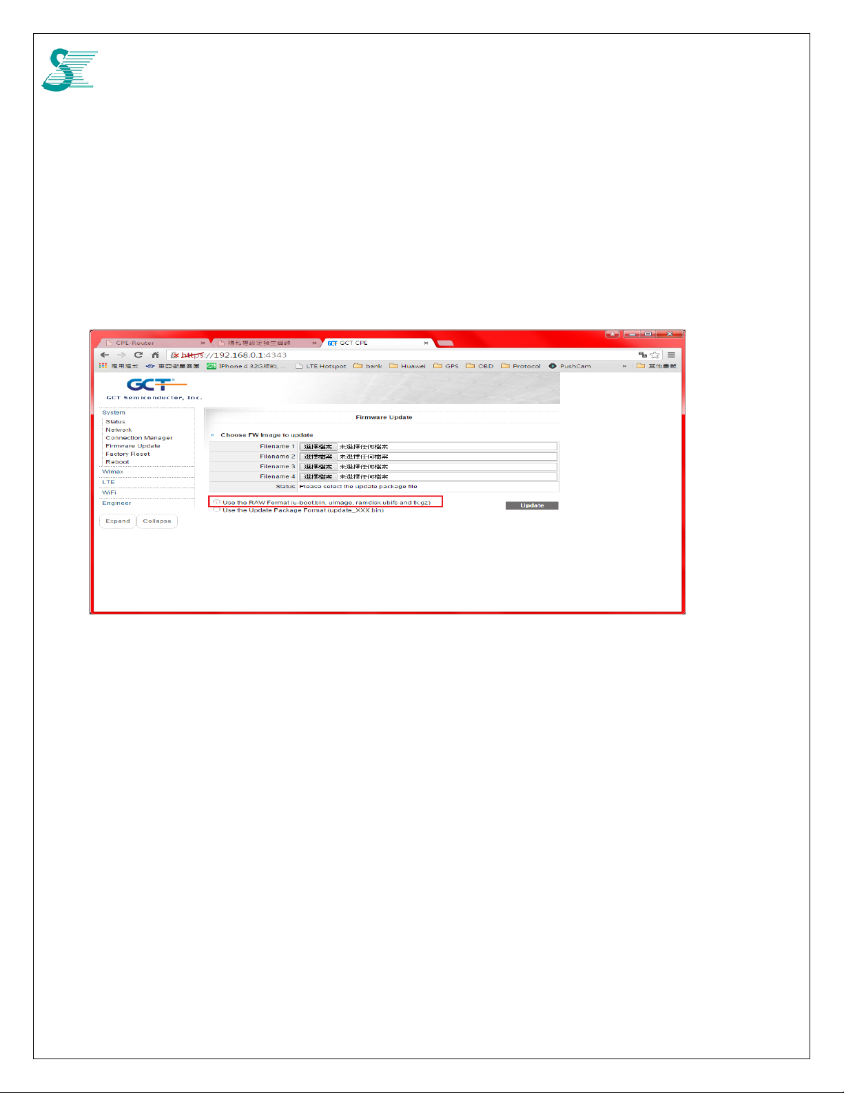
7 FW Upgrade
7.1 Using JIG board or CPE board
If JIP board is used, GCT LTE window driver and ACM driver are required to
install first. When connected PC get IP, 192.168.0.10, from JIG board USB port,
GDM7243Q module GUI can be accessed by http://192.168.0.1
web site link to go to main page.
If using CPE board, access GCT module by http://192.168.0.1
. Click continuous the
Select Firmware update from System Link and Select file from filename 1
RAW Format shall be selected; for xxx.bin, Package Format selected instead.
LTE version can be seen from LTEStatus page.
, click update button. For xxx.gz file,
63
CONFIDENTIAL
7.2 Upgrade FW from 64M to 80M
Two steps required.
Step 1: Get 80M package file and follow the ways to input to module web gui.
1. Select Filename 1 :u-boot-7243q.bin
2. Select Filename 2 :uImage
3. Select Filename 3 :ramdisk.ubifs
4. Select Filename 4 :tk.gz
5. Select RAW Format,
Click Update button, Then the system will move to 80M format.
Step 2: Reset to default
From JIG board console port:
#ucfg clean config
#ucfg clean factory
#ucfg sync
64
 Loading...