

Page 1
Title page
Alcatel-Lucent 9962
Multi-standard Enterprise Cell v1
Technical Description and Troubleshooting Guide
3MN-02001-0003-DEZZA
Issue 3 | November 2015
Page 2

Legal notice
Legal notice
Alcatel, Lucent, Alcatel-Lucent and the Alcatel-Lucent logo are trademarks of Alcatel-Lucent. All other trademarks are the property of their respective
owners.
The information presented is subject to change without notice. Alcatel-Lucent assumes no responsibility for inaccuracies contained herein.
Copyright © 2015 Alcatel-Lucent. All rights reserved.
Page 3

Contents
About this document
Purpose ............................................................................................................................................................................................. ixix
Intended audience
Supported systems
Conventions used
Related information
Document support
Technical support
How to order
How to comment
......................................................................................................................................................................... ixix
........................................................................................................................................................................ ixix
.......................................................................................................................................................................... ixix
..................................................................................................................................................................... ixix
.......................................................................................................................................................................... xx
........................................................................................................................................................................... xx
.................................................................................................................................................................................... xx
........................................................................................................................................................................... xixi
1 Alcatel-Lucent 9962 Multi-standard Enterprise Cell v1 : Overview
Overview
9962 MSEC v1.0 : Product Overview
Small Cells System Architecture
...................................................................................................................................................................................... 1-11-1
............................................................................................................................... 1-21-2
......................................................................................................................................... 1-61-6
9962 MSEC v1.0 : Physical characteristics
.................................................................................................................... 1-71-7
2 Alcatel-Lucent 9962 Multi-standard Enterprise Cell v1 : Functional Description
Overview
Advantages and Functional Description
...................................................................................................................................................................................... 2-12-1
........................................................................................................................... 2-22-2
3 Alcatel-Lucent 9962 Multi-standard Enterprise Cell v1 : Hardware
Overview
9962 MSEC : Hardware Description
Technical Requirements
....................................................................................................................................................................................................................................
Alcatel-Lucent 9962 MSEC v1.0
3MN-02001-0003-DEZZA
Issue 3 November 2015
...................................................................................................................................................................................... 3-13-1
................................................................................................................................. 3-23-2
......................................................................................................................................................... 3-83-8
iii
Page 4

Contents
....................................................................................................................................................................................................................................
4 Troubleshooting using the LED states
Index
Overview
...................................................................................................................................................................................... 4-14-1
LED states for the 3G and 3G/4G 9962 MSEC v1.0
................................................................................................... 4-24-2
....................................................................................................................................................................................................................................
iv
Alcatel-Lucent 9962 MSEC v1.0
3MN-02001-0003-DEZZA
Issue 3 November 2015
Page 5

List of tables
1-1 9962 MSEC Maximum Key Hardward Performances (based on Software used) ............................. 1-41-4
3-1 Frequency bands ........................................................................................................................................................ 3-83-8
3-2 Transmit Power .......................................................................................................................................................... 3-93-9
3-3 Radio Parameters .................................................................................................................................................... 3-103-10
4-1 Power LED initialization ........................................................................................................................................ 4-34-3
4-2 Power LED fault indication ................................................................................................................................... 4-44-4
4-3 Faults that set the Power LED hardware failure ............................................................................................. 4-44-4
4-4 LTE LED startup ........................................................................................................................................................ 4-44-4
4-5 LTE LED fault conditions ...................................................................................................................................... 4-54-5
4-6 WCDMA LED startup ............................................................................................................................................. 4-64-6
4-7 WCDMA LED fault condition .............................................................................................................................. 4-64-6
4-8 GPS LED ...................................................................................................................................................................... 4-74-7
4-9 GPS LED fault condition ........................................................................................................................................ 4-74-7
4-10 WiFi Status LED initialization states ................................................................................................................. 4-84-8
....................................................................................................................................................................................................................................
Alcatel-Lucent 9962 MSEC v1.0
3MN-02001-0003-DEZZA
Issue 3 November 2015
v
Page 6

List of tables
....................................................................................................................................................................................................................................
....................................................................................................................................................................................................................................
vi
Alcatel-Lucent 9962 MSEC v1.0
3MN-02001-0003-DEZZA
Issue 3 November 2015
Page 7

List of figures
1-1 9962 MSEC - Standard model, front view ....................................................................................................... 1-21-2
1-2 Small Cell Solution Architecture ......................................................................................................................... 1-61-6
3-1 9962 MSEC - Front and rear view ...................................................................................................................... 3-23-2
3-2 9962 MSEC - Rear view, with wall mount plate ........................................................................................... 3-33-3
3-3 Power and Input/Output Ports ............................................................................................................................... 3-43-4
3-4 GPS Connector - detailed view ............................................................................................................................ 3-53-5
3-5 Lock slot - detailed view ......................................................................................................................................... 3-53-5
3-6 9962 MSEC Antenna Placement .......................................................................................................................... 3-63-6
4-1 9962 MSEC v1.0 LEDs ........................................................................................................................................... 4-24-2
4-2 WiFi LEDs ................................................................................................................................................................... 4-84-8
....................................................................................................................................................................................................................................
Alcatel-Lucent 9962 MSEC v1.0
3MN-02001-0003-DEZZA
Issue 3 November 2015
vii
Page 8

List of figures
....................................................................................................................................................................................................................................
....................................................................................................................................................................................................................................
viii
Alcatel-Lucent 9962 MSEC v1.0
3MN-02001-0003-DEZZA
Issue 3 November 2015
Page 9

Aboutthis documentAbout this document
Purpose
The purpose of this document is to present a functional and technical description of the
Alcatel-Lucent 9962 Multi-standard Enterprise Cell v1 and its components, as well as
basic trouble-shooting techniques. It is part of the Small Cells product group, and is
designed for commercial use. The short name for the product is 9962 MSEC v1.0.
Intended audience
This document presents an integral overview of the 9962 MSEC v1.0 system, and is
intended for all audiences.
Supported systems
This document applies to the Alcatel-Lucent system for use with W-CDMA and LTE
carriers.
Conventions used
The full product name, Alcatel-Lucent 9962 Multi-standard Enterprise Cell v1, is also
referred to interchangeably as any of the following throughout this document:
• Alcatel-Lucent 9962 MSEC v1.0
• 9962 MSEC v1.0
Related information
For information on subjects related to the content of this document, refer to the
documents listed in the following table:
Refer to this document At this location For information on
Alcatel-Lucent Small Cell
WiFi AP Technical
Description,
3MN-1840-0004-DEZZA
http://support.alcatellucent.com
Descriptions of the WiFi
Access Point's functionality,
physical attributes and
architecture.
...................................................................................................................................................................................................................................
Alcatel-Lucent 9962 MSEC v1.0
3MN-02001-0003-DEZZA
Issue 3 November 2015
ix
Page 10

About this document
....................................................................................................................................................................................................................................
Alcatel-Lucent 9962
Multi-standard Enterprise
Cell v1 - Site Preparation,
3MN-02001-0001-RJZZA
Alcatel-Lucent 9962
Multi-standard Enterprise
Cell v1 - Hardware
Installation,
3MN-02001-0002-RJZZA
Alcatel-Lucent 9962
Multi-standard Enterprise
Cell v1 - Troubleshooting,
3MN-02001-0004-REZZA
Alcatel-Lucent W-CDMA
Radio Access Network,
Terminology Overview,
3MN-01111-0001TQZZA0003-TQZZA
Alcatel-Lucent 9400 LTE
Radio Access Network,
Terminology Overview,
9YZ-04152-0003-TQZZA
http://support.alcatellucent.com
http://support.alcatellucent.com
http://support.alcatellucent.com
http://support.alcatellucent.com
http://support.alcatellucent.com
Site preparation before
installation for the 9962
MSEC v1.0 system.
Installation and
commissioning processes
according to the product
configuration for the 9962
MSEC v1.0 system.
Trouble-shooting guide for
the 9962 MSEC v1.0 system.
A glossary of terms and
abbreviations used for
W-CDMA networks.
A glossary of terms and
abbreviations used for LTE
networks.
Document support
For support in using this or any other Alcatel-Lucent document, contact Alcatel-Lucent at
one of the following telephone numbers:
+1-888-582-3688 (for the United States)
+1-630-224-2485 (for all other countries)
Technical support
For technical support, contact your local Alcatel-Lucent customer support team. See the
Alcatel-Lucent Support web site (http://www.alcatel-lucent.com/support/) for contact
information.
How to order
To order Alcatel-Lucent documents, contact your local sales representative or use Online
Customer Support (OLCS) (http://support.alcatel-lucent.com)
....................................................................................................................................................................................................................................
x
Alcatel-Lucent 9962 MSEC v1.0
3MN-02001-0003-DEZZA
Issue 3 November 2015
Page 11

About this document
....................................................................................................................................................................................................................................
How to comment
To comment on this document, go to the Online Comment Form (http://infodoc.alcatel-
lucent.com/comments/
) or e-mail your comments to the Comments Hotline
(comments@alcatel-lucent.com).
....................................................................................................................................................................................................................................
Alcatel-Lucent 9962 MSEC v1.0
3MN-02001-0003-DEZZA
Issue 3 November 2015
xi
Page 12

About this document
....................................................................................................................................................................................................................................
....................................................................................................................................................................................................................................
xii
Alcatel-Lucent 9962 MSEC v1.0
3MN-02001-0003-DEZZA
Issue 3 November 2015
Page 13

1 1Alcatel-Lucent 9962
Multi-standard Enterprise
Cell v1 : Overview
Overview
Purpose
This chapter provides an overview of the Alcatel-Lucent Small Cells solution, and in
particular the Alcatel-Lucent 9962 Multi-standard Enterprise Cell v1 product.
Contents
9962 MSEC v1.0 : Product Overview 1-2
Small Cells System Architecture 1-6
9962 MSEC v1.0 : Physical characteristics 1-7
...................................................................................................................................................................................................................................
Alcatel-Lucent 9962 MSEC v1.0
3MN-02001-0003-DEZZA
Issue 3 November 2015
1-1
Page 14
Alcatel-Lucent 9962 Multi-standard Enterprise Cell v1 :
Overview
....................................................................................................................................................................................................................................
9962 MSEC v1.0 : Product Overview
9962 MSEC v1.0 : Product Overview
Introduction
The Alcatel-Lucent 9962 Multi-Standard Enterprise Cell, or 9962 MSEC, is a wireless
access point using licensed spectrum delivering improved network reach and increased
capacity while off-loading traffic from the macro network.
It is part of Alcatel-Lucent’s family of Small Cell Solutions.
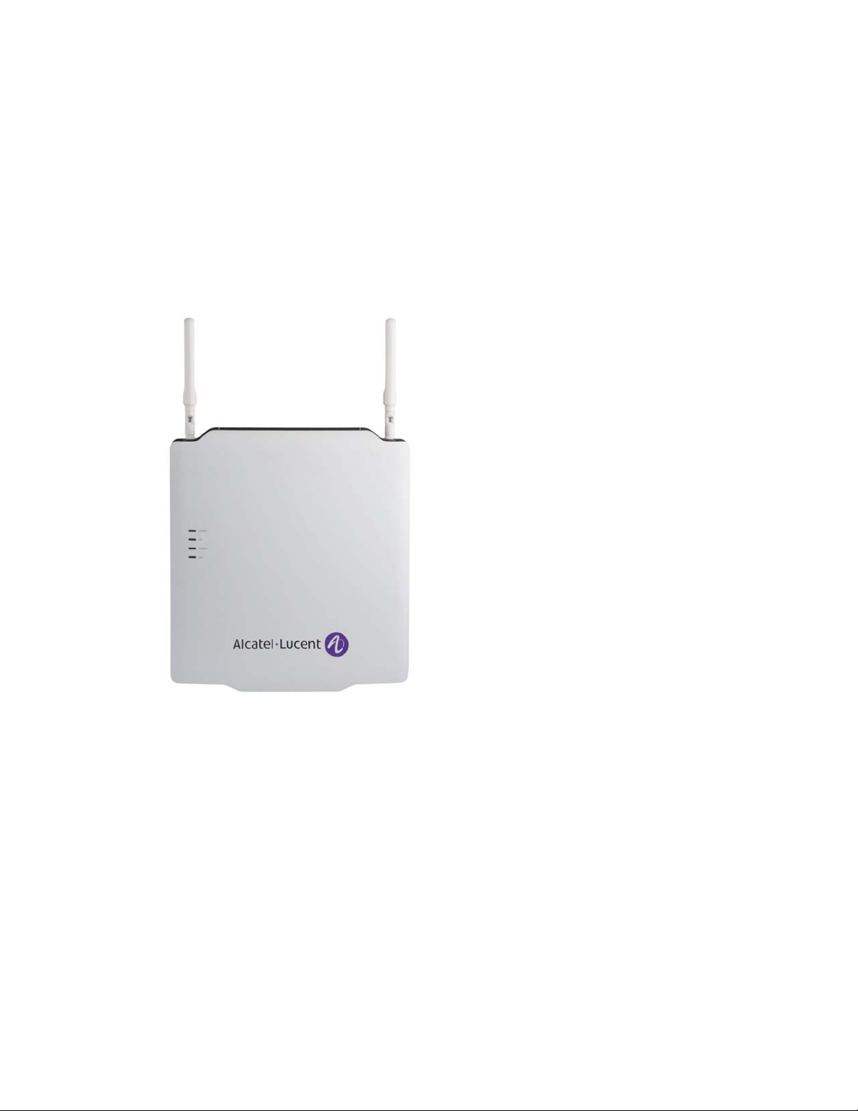
Figure 1-1 9962 MSEC - Standard model, front view
Note: The stick antennas, as pictured, are used only for wall-mount (vertical)
installation - not for ceiling mount (horizontal) installation - and are available
separately from the standard product package.
The 9962 MSEC leverages the latest innovations to provide an indoor small cell that
supports 3G W-CDMA and 4G LTE Radio Access Technology carriers, (using a single
System on Chip, SoC) operating in multiple bands, coupled with an integrated Wi-Fi
Access Point (Wi-Fi AP) functionality.
Its Software Defined Radio (SDR) capability provides the flexibility not only to evolve
from 3G to 4G technology in a given band but also to assign any of the multiple
supported bands to either technology. These software-only changes eliminate the need to
visit the site, thus simplifying maintenance and reducing operating costs.
....................................................................................................................................................................................................................................
1-2
Alcatel-Lucent 9962 MSEC v1.0
3MN-02001-0003-DEZZA
Issue 3 November 2015
Page 15

Alcatel-Lucent 9962 Multi-standard Enterprise Cell v1 :
Overview
....................................................................................................................................................................................................................................
9962 MSEC v1.0 : Product Overview
Integrated omni-directional antennas and optional external antennas are used to extend
coverage, add capacity and improve end-user experience in small, medium and large
indoor environments in a secure, cost effective and easily deployable manner.
Note: Operations in the 5.15-5.25GHz band are restricted to indoor usage only.
Product Capabilities
The 9962 MSEC has sophisticated capabilities developed by Bell Labs to ensure
zero-touch configuration in the case of a single deployment.
The 9962 MSEC has several unique capabilities:
• Designed to blend into most business, office, or warehouse environments.
• It has 2 simultaneous carriers: one LTE and one W-CDMA, or 2 LTE carriers with
Carrier Aggregation;
• It has a capacity up to 64 LTE and 32 W-CDMA active simultaneous users (128 users
in LTE only mode);
• Ithas2x2MIMO configuration with transmit and receive diversity for LTE, and 1 x
2 receive diversity for W-CDMA;
• It uses a single cable for power with 4p PoE (Power over HD Base-T) and backhaul;
• It has a common backhaul across 3G/4G/Wi-Fi via one RJ45 and one SFP Port.
It has 7 integrated omni-directional antennas and 2 attached dipole antennas :
• 4 antennas are dedicated to RAN access, one is used for sniffing RAN frequency
bands, 4 are dedicated to WiFi
• The Multi-Standard Enterprise Cell can support a set of external antennas.
• The internal or external antenna configuration is performed during hardware
installation (and is reversible).
• The two configurations allow flexible installation and indoor coverage optimization.
For specific solutions, the customer may use their own antennas (directional,
omni-directional) but must ensure that the necessary certifications are valid.
The 9962 Multi-Standard Enterprise Cell has also Wi-Fi capabilities:
• The Wi-Fi version module is Wi-Fi Certified™ ;
• IEEE 802.11n with dual-band dual-concurrent communication;
• Integrated antennas optimized for 2x2 MIMO, and up to 125/100 mW Tx power per
path;
• 20/40 MHz bandwidth
• Maximum physical data throughput of 2x300Mbps;
• Supports up to 256 connected users;
....................................................................................................................................................................................................................................
Alcatel-Lucent 9962 MSEC v1.0
3MN-02001-0003-DEZZA
Issue 3 November 2015
1-3
Page 16

Alcatel-Lucent 9962 Multi-standard Enterprise Cell v1 :
Overview
....................................................................................................................................................................................................................................
9962 MSEC v1.0 : Product Overview
• 32 SSIDs (16 per frequency band).
• The Wi-Fi internal antennas typical peak gain values are: 2.4GHz band: 5.4 dBi;
5GHz band 5.2 dBi.
Refer to the Alcatel-Lucent Small Cell Wi-Fi AP Technical Description,
3MN-01840-0004-DEZZA, for more information regarding the Wi-Fi Access Point
functionality.
Technical Performance
Table 1-1 9962 MSEC Maximum Key Hardward Performances (based on Software
used)
Maximal Performance
Capacities:
Maximum transmit power : 2 x 250 mW (2 x 24dBm) 250 mW (24 dBm)
Number of users: Up to 32 Up to 32
Peak data rate: DL: up to 75 Mbps
Technical Specifications Summary
Wi-Fi Capability
• Carrier grade Wi-Fi
• Dual-Band: Simultaneous support of 2.4/5GHz
• 802.11 n
• 2x2 MIMO
• Tx Power up to 19dBm in 2.4 GHz and 18dBm in 5GHz
• Integrated antenna in the module and external antenna option.
Interfaces
LTE W-CDMA
UL: up to 37 Mbps
DL: up to 21 Mbps
UL: up to 5.7 Mbps
• GPS antenna
• External Antenna Connectors
• RJ45 and SFP
• 48 V DC Input
Power Supply
• Power over HD Base-T (4p POE)
• 48V DC
• Typical power consumption at ambient temperature: ~48W
• AC/DC convertor provided to power the unit via AC
....................................................................................................................................................................................................................................
1-4
Alcatel-Lucent 9962 MSEC v1.0
3MN-02001-0003-DEZZA
Issue 3 November 2015
Page 17

Alcatel-Lucent 9962 Multi-standard Enterprise Cell v1 :
Overview
....................................................................................................................................................................................................................................
9962 MSEC v1.0 : Product Overview
Certifications and standards
• FCC Part 15 Subpart B Class B
• Safety: CSA-C22.2 No. 60950-1-07/UL 60950-1
• IPX2 certified
Environmental parameters
• Temperature range: 0°C to +50°C
• Relative humidity: Up to 93%
• Passive Cooling
Synchronization and Timing
• GPS
• NTP
Radio Characteristics
• Operating bands:
– W-CDMA (3G): B2 (PCS/1900MHz), B5 (850 MHz)
– LTE (4G): B2 (PCS/1900MHz) , B4 (AWS), B12 (700 MHz);
• 2x2 MIMO configuration with 2 transmit and 2 path receive diversity for LTE, and
1x2 W-CDMA
• Maximum transmission power: LTE 2x250 mW (24dBm) per path, W-CDMA 1x250
mW (24 dBm)
• Up to 64 LTE and 32 W-CDMA active simultaneous users (up to 128 users in
LTE-only mode)
• LTE Peak rate support (75Mb/s down link and 37 Mb/s uplink at 10 MHz, 150Mb/s
down link and 75 Mb/s uplink at 20 MHz)
• Network sniffing
....................................................................................................................................................................................................................................
Alcatel-Lucent 9962 MSEC v1.0
3MN-02001-0003-DEZZA
Issue 3 November 2015
1-5
Page 18

Alcatel-Lucent 9962 Multi-standard Enterprise Cell v1 :
Overview
....................................................................................................................................................................................................................................
Small Cells System Architecture
Small Cells System Architecture
Overview
The Alcatel-Lucent Small Cell unit uses 3GPP interfaces to connect to neighboring
eNodeBs and other existing mobile core network nodes, while offering a 3GPP-compliant
air interface. The architecture integrates seamlessly into existing LTE and UMTS
networks, including interfaces to other components, as well as to existing management
systems, and therefore integrates with existing applications, portals, and services through
standard interfaces.
Figure 1-2 Small Cell Solution Architecture
The Small Cell unit interconnects with the core network elements with the addition of a
Security Gateway (SeGW), a 3G Small Cell GW (HNB-GW) and optionally a HeNB-GW
between the unit and the 3G/LTE core elements.
It supports S1-MME and S1-U interfaces based on 3GPP specifications as per macro
eNodeB. The unit has connectivity to all MMEs/SGWs (located in the core network) in
the pool/serving area. The S1-flex function and requirements for the unit differ from those
for the macro eNodeB, as it is on the HeNB-GW, instead of on the unit itself.
The Serving Gateway (SGW) selection function selects an available SGW to serve a UE.
The SGW selection function is performed by the MME and does not require any changes
to support the unit.
....................................................................................................................................................................................................................................
1-6
Alcatel-Lucent 9962 MSEC v1.0
3MN-02001-0003-DEZZA
Issue 3 November 2015
Page 19

Alcatel-Lucent 9962 Multi-standard Enterprise Cell v1 :
Overview
....................................................................................................................................................................................................................................
9962 MSEC v1.0 : Physical characteristics
9962 MSEC v1.0 : Physical characteristics
Overview
The following are the physical characteristics of the Alcatel-Lucent 9962 Multi-standard
Enterprise Cell v1.
The physical dimensions of the system are estimated as follows :
• Height : 355 mm
• Width : 326 mm
• Depth : 56 mm to 96 mm
Weight
• 5.8 kg
....................................................................................................................................................................................................................................
Alcatel-Lucent 9962 MSEC v1.0
3MN-02001-0003-DEZZA
Issue 3 November 2015
1-7
Page 20

Alcatel-Lucent 9962 Multi-standard Enterprise Cell v1 :
9962 MSEC v1.0 : Physical characteristics
Overview
....................................................................................................................................................................................................................................
....................................................................................................................................................................................................................................
1-8
Alcatel-Lucent 9962 MSEC v1.0
3MN-02001-0003-DEZZA
Issue 3 November 2015
Page 21

2 2Alcatel-Lucent 9962
Multi-standard Enterprise
Cell v1 : Functional
Description
Overview
Purpose
This chapter presents a functional description and use cases of the 9962 MSEC v1.0.
Contents
Advantages and Functional Description 2-2
...................................................................................................................................................................................................................................
Alcatel-Lucent 9962 MSEC v1.0
3MN-02001-0003-DEZZA
Issue 3 November 2015
2-1
Page 22

Alcatel-Lucent 9962 Multi-standard Enterprise Cell v1 :
Functional Description
....................................................................................................................................................................................................................................
Advantages and Functional Description
Advantages and Functional Description
Use Cases
The Alcatel-Lucent 9962 Multi-Standard Enterprise Cell is designed for deployment in an
indoor environment with its associated environmental and physical constraints. Therefore,
it can be installed in many indoor private places such as business offices or warehouses,
as well as in numerous indoor public places (supermarkets, shopping malls, airports…)
The 9962 MSEC installation will depend on local or national laws in the country where
the product is deployed.
Product Benefits
Since the 9962 MSEC can be installed in a wide variety of indoor places, it can offer
many benefits to customers using those spaces.
If installed in business offices, new sources of revenue from corporate applications can
be enabled by the enhanced indoor coverage and corporate networking possibilities. For
instance, with the presence location API feature, the users can be connected to the Small
Cell Access Points to take advantage of enterprise services. For example, workers can be
connected to the company anytime, anywhere through a mobile application. They can
make and receive their business calls as if they were in their office, thanks to a “One
Number” capability.
Options such as call history, visual voice mails, corporate directory, and call routing are
available on this kind of mobile application.
If installed in indoor public places, the 9962 MSEC can be deployed in areas formerly
covered by microcells or picocells, but can also be used in many more cases, instead of
macrocells, since they are very easy to install and are less subject to regulatory constraints
with their low emission power.
With its high capacity, the Enterprise Cell is ideal for high user-density places where
additional capacity is required or even in areas where cell phone coverage is needed on
short notice. This deployment also allows new, innovative applications such as location,
Quality of Service (QoS) and trusted security for application development.
Enterprise Cells also allow the operator to propose bundled offers and to include an entire
group of employees into a single agreement. This leads to a reduction of customer churn,
and allows higher revenue per user.
....................................................................................................................................................................................................................................
2-2
Alcatel-Lucent 9962 MSEC v1.0
3MN-02001-0003-DEZZA
Issue 3 November 2015
Page 23

Alcatel-Lucent 9962 Multi-standard Enterprise Cell v1 :
Functional Description
....................................................................................................................................................................................................................................
Auto-configuration and self-optimisation
Advantages and Functional Description
The Network Listening feature is used for auto-configuration and self-optimisation of
the radio. It allows the 9962 Multi-Standard Enterprise Cell to act as a UE and receive
transmission from neighboring base stations. It is used to automatically identify, measure
and record its neighbor cells, reducing the need for operator-provisioned neighbor cell
lists.
The information is then used by the 9962 Multi-Standard Enterprise Cell to automatically
select:
• its Physical Cell id (PCI) and to create and update a list of neighbor cells before UE
measurements are received
• its primary scrambling code and power levels to transmit, and to create and update a
list of UMTS neighbor cells
Those neighbor cell lists are used by the 9962 Multi-Standard Enterprise Cell for
identification of the target cell for hand-over and for rebroadcasting of the system
information messages, in support of re-selection by the UE.
The Wi-Fi part is a dual-band dual-concurrent module, supporting:
Security
• Frequency bands: 2.4 and 5 GHz.
• Bandwidths: 20 and 40 MHz.
The 9962 Multi-Standard Enterprise Cell security solution offers robust and mature
security features to protect the Small Cell system against increasing security risks
resulting from exposure to untrusted areas.
This security solution is based on a long security hardening experience from W-CDMA
Small Cell, LTE wireless security knowledge and customer feedback and lessons learned
in this area, such as:
• IPsec tunnel for traffic integrity protection and encryption for OAM, control plane,
user plane
• Certificate-based authentication and security with Secure boot, Trusted Environment
to ensure the confidentiality and integrity of sensitive information on the Enterprise
Cell, and Authentication of the Enterprise Cell to the SeGW by Certificate as per
3GPP TS33.320.
• Security hardening of the 9962 Multi-Standard Enterprise Cell
• Tamper Alarm
• Evolved Packet System
Forced opening of the casing causes permanent disablement of the unit. In this case, the
repair process is not applicable, as irreversible damage is caused to the printed circuit
board and a new one must be provided.
....................................................................................................................................................................................................................................
Alcatel-Lucent 9962 MSEC v1.0
3MN-02001-0003-DEZZA
Issue 3 November 2015
2-3
Page 24

Alcatel-Lucent 9962 Multi-standard Enterprise Cell v1 :
Advantages and Functional Description
Functional Description
....................................................................................................................................................................................................................................
....................................................................................................................................................................................................................................
2-4
Alcatel-Lucent 9962 MSEC v1.0
3MN-02001-0003-DEZZA
Issue 3 November 2015
Page 25

3 3Alcatel-Lucent 9962
Multi-standard Enterprise
Cell v1 : Hardware
Overview
Purpose
This chapter presents the hardware of the 9962 MSEC v1.0.
Contents
9962 MSEC : Hardware Description 3-2
Technical Requirements 3-8
...................................................................................................................................................................................................................................
Alcatel-Lucent 9962 MSEC v1.0
3MN-02001-0003-DEZZA
Issue 3 November 2015
3-1
Page 26

Alcatel-Lucent 9962 Multi-standard Enterprise Cell v1 :
Hardware
....................................................................................................................................................................................................................................
9962 MSEC : Hardware Description
9962 MSEC : Hardware Description
Product Characteristics
Deployment Scenario : The Alcatel-Lucent 9962 Multi-Standard Enterprise Cell is
designed for use in an indoor environment, to be installed vertically, using the optional
wall bracket, or horizontally.
Customization options
The 9962 MSEC case has a number of customization options. Below are pictures of the
standard enclosure, front and back view:
Figure 3-1 9962 MSEC - Front and rear view
Note: The stick antennas, as pictured, are used only for wall-mount (vertical)
installation - not for ceiling mount (horizontal) installation - and are available
separately from the standard product package.
....................................................................................................................................................................................................................................
3-2
Alcatel-Lucent 9962 MSEC v1.0
3MN-02001-0003-DEZZA
Issue 3 November 2015
Page 27

Alcatel-Lucent 9962 Multi-standard Enterprise Cell v1 :
Hardware
....................................................................................................................................................................................................................................
9962 MSEC : Hardware Description
Figure 3-2 9962 MSEC - Rear view, with wall mount plate
Product delivery contents
The standard 9962 MSEC v1.0 is provided in a cardboard box with the following
contents:
• The 9962 MSEC v1.0 access point,
• A mounting kit (wall or ceiling) including M5 steel screws to be used with N°2 driver,
• A quick start guide/user guide.
The standard package can be customized on demand.
The custom-tailoring process allows the option of adding the following items to the
standard package :
• one GPS antenna with 10m cable length included,
• two RF stick antennas in case of wall-mounted installation.
The GPS antenna acquisition sensitivity is:
• -160dBm/Hz with AGPS server assistance and 2.5dB NF,
• -158dBm/Hz, unassisted.
....................................................................................................................................................................................................................................
Alcatel-Lucent 9962 MSEC v1.0
3MN-02001-0003-DEZZA
Issue 3 November 2015
3-3
Page 28

Alcatel-Lucent 9962 Multi-standard Enterprise Cell v1 :
Hardware
....................................................................................................................................................................................................................................
Ancillary items
9962 MSEC : Hardware Description
In addition to the standard delivered parts, the following ancillary items may be required.
They may be purchased separately from Alcatel-Lucent, or purchased locally :
• two RF stick antennas for use in wall-mounted installation,
• SFP transceiver,
• Ethernet and/or fiber cable,
• 4p PoE compliant with PoH standard adapter,
• AC to DC power adapter,
• Lock,
• RF antenna jumper,
• GPS extension cable.
Connectors and Interfaces
The following connectors and interfaces are part of the 9962 MSEC solution :
• 1 Gigabit Ethernet connector (1000Base-T RJ-45) for backhauling or daisy-chaining.
If 4p PoE is used to supply the power, this connector is to be connected to a 4p PoE
capable router or a 4p PoE injector when the DC power connector is not used.
• 1 SFP interface for backhauling or daisy-chaining which supports a 1000base-X GbE
optical transceiver or 100/1000Base-T electrical transceiver
• Jack connector for power supply. When the AC/DC power adaptor is used to supply
the power, the PoE capable router is not used
• 1 SMA-type connector for the GPS antenna
• 9 SMA-type connectors for the external antenna version
• A lock slot
• 6 bi-color LEDs to provide the status of the unit
• A re-set button
Figure 3-3 Power and Input/Output Ports
....................................................................................................................................................................................................................................
3-4
Alcatel-Lucent 9962 MSEC v1.0
3MN-02001-0003-DEZZA
Issue 3 November 2015
Page 29

Alcatel-Lucent 9962 Multi-standard Enterprise Cell v1 :
Hardware
....................................................................................................................................................................................................................................
9962 MSEC : Hardware Description
Figure 3-4 GPS Connector - detailed view
Figure 3-5 Lock slot - detailed view
Antennas
The 9962 Multi-Standard Enterprise Cell supports 4 polarized antennas configured for
2x2 MIMO with 2 transmit and 2 receive paths diversity for LTE, and 1x2 MIMO with 1
transmit and 2 receive paths diversity for W-CDMA.
Two internal omnidirectional W-CDMA and LTE antennas are included in the 9962
MSEC for B2/B5:
• Typical peak gain for internal antennas at B2 frequency: 3.2 dBi.
• Typical peak gain for internal antennas at B5 frequency: 1.8 dBi.
Two external omnidirectional “stick” antennas are available for B4/B12 frequencies :
• Typical peak gain for RAN attached dipole antenna at B4 frequency: 1.8 dBi
• Typical peak gain for RAN attached dipole antenna at B12 frequency: 2.3 dBi
....................................................................................................................................................................................................................................
Alcatel-Lucent 9962 MSEC v1.0
3MN-02001-0003-DEZZA
Issue 3 November 2015
3-5
Page 30

Alcatel-Lucent 9962 Multi-standard Enterprise Cell v1 :
Hardware
....................................................................................................................................................................................................................................
9962 MSEC : Hardware Description
A version with external, omni-directional antennas is available. The average gain of the
given antennas is the same as the internal ones, but offers a better coverage with a
superior peak gain :
• Typical peak gain for external antenna at B4 or B12 frequency: up to 5 dBi
(depending on the design)
• Typical peak gain for external antenna at B2 and B5 frequency: up to 5 dBi
(depending on the design)
For specific solutions, the customer may use their own antennas (directional,
omni-directional…) but must ensure that the necessary certifications are valid.
Figure 3-6 9962 MSEC Antenna Placement
The minimum value is 10 dBm (10mW).
Wi-Fi Parameters
The Wi-Fi module supports 4 integrated antennas optimized for 2x2 MIMO with up to 2
spatial streams. It uses advanced antenna design to support IEEE standard 802.11n,
providing optimized MIMO performance and coverage.
The Wi-Fi internal antennas peak gain values are:
• 2.4GHz band: 5.4dBi
• 5GHz band 5.2 dBi
For a detailed description of the internal Wi-Fi Access Point attenas, refer to the
Alcatel-Lucent Small Cell Wi-Fi AP Technical Description, 3MN-01840-0004-DEZZA, .
5620 Service Aware Manager (SAM)
The Alcatel-Lucent 5620 Service Aware Manager, or 5620 SAM, enables end-to-end
network and service management of Alcatel-Lucent NEs, and limited management of
third-party NEs. Third-party NEs are referred to as generic NEs, or GNEs.
....................................................................................................................................................................................................................................
3-6
Alcatel-Lucent 9962 MSEC v1.0
3MN-02001-0003-DEZZA
Issue 3 November 2015
Page 31

Alcatel-Lucent 9962 Multi-standard Enterprise Cell v1 :
Hardware
....................................................................................................................................................................................................................................
9962 MSEC : Hardware Description
The 5620 SAM performs the following tasks :
• It provisions a network with fast and easy configuration and multi-vendor scripting
workflows that reduce the risk of error and shorten network deployment time.
• It accelerates set-up for integrated IP/optical performance and SLA monitoring with
service-aware diagnostics that validate end-to-end services and IP/optical paths.
• It prevents service degradation through end-to-end power control, monitoring, tracing,
and fault localization.
• It correlates faults to identify whether the problem resides in the IP or optical layer,
and the root cause. This function simplifies troubleshooting and isolates problems
before services are affected.
....................................................................................................................................................................................................................................
Alcatel-Lucent 9962 MSEC v1.0
3MN-02001-0003-DEZZA
Issue 3 November 2015
3-7
Page 32

Alcatel-Lucent 9962 Multi-standard Enterprise Cell v1 :
Hardware
....................................................................................................................................................................................................................................
Technical Requirements
Technical Requirements
Power Supply
The power supply requirements and consumption are as follows :
• If a Power supply over 4p PoE is used to supply the power, a 4p PoE injector can be
used while the AC/DC power connector is not used. Otherwise, a 4p PoE capable
router can also be used. 4p PoE capable router and 4p PoE injector are not part of the
standard product delivery.
• Power supply with AC/DC power adaptor : The Multi-standard Enterprise Cell v1
requires a 48V DC power feed. In this case, power injector is not used but a AC/DC
power adaptor is needed.
• Power consumption : The maximum power consumption of the Enterprise Cell
depends on the transmit power.
The power consumption on the 250 mW variant is approximately 48 W.
Frequency Bands
The Alcatel-Lucent Enterprise Cell Multi-Standard supports 5, 10, 15 and 20 MHz carrier
bandwidths for LTE and 5 MHz carrier bandwidth for W-CDMA applications.
Supported band and frequencies are provided in the table below:
Table 3-1 Frequency bands
Operating
Band for LTE
II 1900 PCS 1850 – 1910
IV 1700 AWS 1710 – 1755
XII 700 LMSH A/B/C 699 – 716 MHz 729 – 746 MHz
Operating
Band for UMTS
Operation
II 1900 PCS 1850 – 1910
Frequency
Band
Frequency
Band
Common
Name
Common
Name
UL
Frequencies
MHz
MHz
UL
Frequencies
MHz
DL
Frequencies
1930 – 1990
MHz
2110 – 2155
MHz
DL
Frequencies
1930 – 1990
MHz
V 850 CLR 824 - 849 MHz 869 - 894 MHz
....................................................................................................................................................................................................................................
3-8
Alcatel-Lucent 9962 MSEC v1.0
3MN-02001-0003-DEZZA
Issue 3 November 2015
Page 33

Alcatel-Lucent 9962 Multi-standard Enterprise Cell v1 :
Hardware
....................................................................................................................................................................................................................................
Technical Requirements
Operating
Band for
Frequency
Band
Common Name UL Frequencies DL Frequencies
Network
Listening
II 1900 PCS - 1930 – 1990
MHz
LTE and 3G
Network
Listening
IV 1700 AWS - 2110 – 2155
MHz
LTE
Network
Listening
V 850 CLR - 869 - 894 MHz
3G Network
Listening
XII 700 LMSH A/B/C - 729 – 746 MHz
Transmission Power
The Multi-standard Enterprise Cell v1 is capable of output power up to 2x250 mW
(250mW at each antenna connector). Due to its transmit power, the 9962 MSEC v1.0 is
part of the 3GPP Local Area BS classification. It is configurable in 1 dB steps from
minimum to maximum configuration.
The minimum value is 10 dBm (10mW).
The Wi-Fi transmit power has a minimum conducted TX power per chain of
21dBm/20dBm for 2,4/5GHz band and is configurable in 1 dB steps from minimum to
maximum configuration.
Table 3-2 Transmit Power
Radio Access
Technology
LTE
Network
Listening
W-CDMA, LTE W-CDMA, LTE WiFi
Frequency band: 1900 /1700 MHz 850/700 MHz 2.4 GHz 5 GHz
....................................................................................................................................................................................................................................
Alcatel-Lucent 9962 MSEC v1.0
3MN-02001-0003-DEZZA
Issue 3 November 2015
3-9
Page 34

Alcatel-Lucent 9962 Multi-standard Enterprise Cell v1 :
Hardware
....................................................................................................................................................................................................................................
Technical Requirements
Table 3-2 Transmit Power (continued)
Radio Access
Technology
Max conducted
power per chain
(dBm):
Typical Max
EIRP (dBm) per
band:
Radio Parameters
The Enterprise Cell Multi-Standard is designed according to the following parameters in
3GPP TS 25.104 and 3GPP TS 36.104 specifications.
Table 3-3 Radio Parameters
Sensitivity : -116.5 dBm - 107 dBm (or
W-CDMA, LTE W-CDMA, LTE WiFi
23 24 FCC : 19
Depending on antenna gain FCC : 28
Parameter W-CDMA Value 3GPP 25.104
requirement
less)
FCC:18
ETSI : 11
ETSI : 18
FCC:26
ETSI : 20
ETSI : 26
LTE Value 3GPP 36.104
requirement
-94.5 -93.5
Reliability
QPSK EVM 17.5% 17.5% (or less) 17.5% 17.5%
16QAM EVM 12.5% 12.5% (or less) 12.5% 12.5%
64QAM EVM 7% - 7% 8%
ACLR 5MHz 45 dB 45 dB (or
45 dB 45 dB
greater)
ACLR 10MHz 50 dB 50 dB (or
45 dB 45 dB
greater)
The MTBF (Mean Time Between Failures) is calculated based on Telcordia SR-332 Issue
2, September 2006.
The MTBF of the Enterprise Cell Multi-Standard v1.0 at 25°C on a stand position is
356,000 hours.
....................................................................................................................................................................................................................................
3-10
Alcatel-Lucent 9962 MSEC v1.0
3MN-02001-0003-DEZZA
Issue 3 November 2015
Page 35

Alcatel-Lucent 9962 Multi-standard Enterprise Cell v1 :
Hardware
....................................................................................................................................................................................................................................
Technical Requirements
Status Indicators
Six bi-color LEDs provide indication for the system:
• Power
• LTE
• W-CDMA
• GPS status
• 2 rear LEDs indicate Wi-Fi status, labelled 2G and 5G
When the system is fully working for 15 minutes, the LEDs are extinguished.
Assuming the service functions normally, the system status LED color is green. In
addition, it is possible to monitor different status elements following a LED sequence
described later in this user guide, in the chapter on Troubleshooting.
....................................................................................................................................................................................................................................
Alcatel-Lucent 9962 MSEC v1.0
3MN-02001-0003-DEZZA
Issue 3 November 2015
3-11
Page 36

Alcatel-Lucent 9962 Multi-standard Enterprise Cell v1 :
Technical Requirements
Hardware
....................................................................................................................................................................................................................................
....................................................................................................................................................................................................................................
3-12
Alcatel-Lucent 9962 MSEC v1.0
3MN-02001-0003-DEZZA
Issue 3 November 2015
Page 37

4 4Troubleshooting using the
LED states
Overview
Purpose
This chapter details LED status and their meaning for the 9962 MSEC v1.0 product and
troubleshooting.
Contents
LED states for the 3G and 3G/4G 9962 MSEC v1.0 4-2
...................................................................................................................................................................................................................................
Alcatel-Lucent 9962 MSEC v1.0
3MN-02001-0003-DEZZA
Issue 3 November 2015
4-1
Page 38

Troubleshooting using the LED states LED states for the 3G and 3G/4G 9962 MSEC v1.0
....................................................................................................................................................................................................................................
LED states for the 3G and 3G/4G 9962 MSEC v1.0
Overview
This topic describes the states of the LEDs on the 9962 MSEC v1.0 device.
There are two variants of the 9962 MSEC v1.0:
• 3G only
• 3G and 4G (LTE)
There are six red/green bicolored LEDs that indicate the status:
• Power
• LTE cells: only on the 3G/4G variant
• W-CDMA cell
• GPS receiver
• 2 WiFi module status indicators on the rear of the unit, labelled 2G and 5G.
Figure 4-1 9962 MSEC v1.0 LEDs
The LEDs can take these states:
• Off
• flashing green
• solid green
• flashing red
• solid red
• toggling between red and green
....................................................................................................................................................................................................................................
4-2
Alcatel-Lucent 9962 MSEC v1.0
3MN-02001-0003-DEZZA
Issue 3 November 2015
Page 39

Troubleshooting using the LED states LED states for the 3G and 3G/4G 9962 MSEC v1.0
....................................................................................................................................................................................................................................
LED interpretation
When the 9962 MSEC v1.0 is powered on, all LEDs are solid red: if the software fails to
start, the LEDs remain in this condition. Otherwise the LEDs indicate the progress of the
initialization of the unit.
After the four LEDs, excluding the WiFi LEDs, have been in a normal state for fifteen
minutes, these four LEDs are all turned off to avoid bringing attention to the unit. If an
event occurs that changes an LED state, then the four LEDs are turned on. After the LEDs
have returned to normal state for fifteen minutes, all LEDs are turned off again.
The WiFi status LEDs act independently of this management.
Power LED
The system initialization and fault states are represented by a single bicolored red/green
LED.
Table 4-1 Power LED initialization
System state LED state Description
Power off OFF Power is off
Boot Red Power is applied or the system is reset.
During this phase the BLST is performed, DHCP access
is made and the IP address is assigned.
The system remains in this state if the boot fails or
BLST fails.
Network attach flashing red The system attempts to establish contact with the DNS
external server.
The system negotiates with the Security Gateway and
establishes an OAM IPSec tunnel.
EMS connect Toggling
red/green
Download and
flashing green The system is verifying the 9962 MSEC v1.0 software
configuration
Attempt to contact DNS Internal for HDM/SAM address
resolution
and database.
It updates if necessary, followed by a reset.
System stable Green Software and database are current, and the system is
ready to enable applications
....................................................................................................................................................................................................................................
Alcatel-Lucent 9962 MSEC v1.0
3MN-02001-0003-DEZZA
Issue 3 November 2015
4-3
Page 40

Troubleshooting using the LED states LED states for the 3G and 3G/4G 9962 MSEC v1.0
....................................................................................................................................................................................................................................
In the case where a fault is detected, the LED turns red.
Table 4-2 Power LED fault indication
LED state Description Comment
Red Hardware fault is detected such that
no service can be provided or service
is degraded
The LTE and WCDMA LEDs
indicate whether service is still
active.
If either is not active, see
“Faults that set the Power LED
hardware failure” (p. 4-4)
that set this LED.
The LED fault state clears when the
fault clears or the unit is reset
Red 9962 MSEC v1.0 temperature is
outside of the supported range.
Service may be affected by extreme
temperature conditions.
The LED fault state clears when the
fault clears or the unit is reset
Table 4-3 Faults that set the Power LED hardware failure
Hardware Fault Comment
Ethernet switch May prevent backhaul communication
RF transceiver Blocks or degrades air interface operation
Table 4-3,
for faults
Oscillator module failure Affects all clock and frequency generation
Network listen receiver Affects network listen function
LTE LED
The LTE start-up sequence and fault state are indicated by a single bicolored red/green
LED. This LED is only managed in the 3G/4G variant.
Table 4-4 LTE LED startup
State LED state Description
Power off OFF Power off
Booting and
BLST
....................................................................................................................................................................................................................................
4-4
Red Power on or restart
Alcatel-Lucent 9962 MSEC v1.0
3MN-02001-0003-DEZZA
Issue 3 November 2015
Page 41

Troubleshooting using the LED states LED states for the 3G and 3G/4G 9962 MSEC v1.0
....................................................................................................................................................................................................................................
Table 4-4 LTE LED startup (continued)
State LED state Description
System
initializing
(timing, RF,
cell) and begin
location check
Location check
failure
Toggling
red/green
flashing red The 9962 MSEC v1.0 remains in this state if the location
Establishing resources needed by the LTE cell. The 9962
MSEC v1.0 may leave this state before the location
check completes if
passiveGPS
is True.
Otherwise it remains in this state until the location check
completes.
check or movement check fails and
showLocationCheck
is True
Unit reset is required to clear the state.
Boot complete Off LED comes on initially but is turned off once the
Cell unlocked
and ready for
software starts and
Green Location check may be running in the background or no
location check to be performed
operatingMode
is WCDMA-only.
service (LTE cell
AST Unlocked
and OST
Enabled)
In the case where a fault is detected, the LED indicates the fault.
Table 4-5 LTE LED fault conditions
LED state Description Comment
flashing green Cell blocked.
LTE cell AST set to
Locked, or OST is
Disabled due to ongoing
Network Listen activity
Red Cell failure
LTE cell OST is Disabled
for any reason other than
ongoing Network Listen
activity
Cell successfully configured but not
transmitting
The LED fault state clears when the cell is
unlocked or Network Listen completes and
OST is now Enabled.
cell configuration failure, cell operational
failure reported by 3G application, WCDMA
tunnel down, SCTP association failure or
another fault.
The LED fault state clears when the cell is
reconfigured and unblocked.
....................................................................................................................................................................................................................................
Alcatel-Lucent 9962 MSEC v1.0
3MN-02001-0003-DEZZA
Issue 3 November 2015
4-5
Page 42

Troubleshooting using the LED states LED states for the 3G and 3G/4G 9962 MSEC v1.0
....................................................................................................................................................................................................................................
WCDMA LED
The WCDMA start-up sequence and fault state are indicated by a single bicolored
red/green LED.
Table 4-6 WCDMA LED startup
State LED state Description
Power off OFF Power off
Booting and
Red Power on or restart
BLST
System
initializing
(timing, RF,
cell) and begin
location check
Toggling
red/green
Establishing resources needed by the LTE cell. The 9962
MSEC v1.0 may leave this state before location check
completes if
passiveGPS
is True.
Otherwise it remains in this state until the location check
completes.
Location failure flashing red The 9962 MSEC v1.0 remains in this state if location
check or movement check fails and
showLocationCheck
is True
Unit reset is required to clear this state.
Cell unlocked
and ready for
Green Location check may be running in the background or no
location check to be performed
service (LTE cell
AST Unlocked
and OST
Enabled)
In the case where a fault is detected, the LED indicates the fault.
Table 4-7 WCDMA LED fault condition
LED state Description Comment
flashing green Cell blocked.
LTE cell AST is set to
Locked, or OST is
Disabled due to ongoing
Network Listen activity
....................................................................................................................................................................................................................................
4-6
Cell successfully configured but not
transmitting
The LED fault state clears when the cell is
unlocked or Network Listen completes and
OST is now Enabled.
Alcatel-Lucent 9962 MSEC v1.0
3MN-02001-0003-DEZZA
Issue 3 November 2015
Page 43

Troubleshooting using the LED states LED states for the 3G and 3G/4G 9962 MSEC v1.0
....................................................................................................................................................................................................................................
Table 4-7 WCDMA LED fault condition (continued)
LED state Description Comment
Red Cell failure cell configuration failure, cell operational
failure reported by 3G application, WCDMA
tunnel down, SCTP association failure or
another fault.
The LED fault state clears when the LTE cell
OST is Enabled, WCDMA tunnel is ready
GPS LED
The status and fault condition of the GPS are represented by a single bicolored red/green
LED.
Table 4-8 GPS LED
State LED state Description
Power off OFF Power off
Boot and BLST
in progress
Red Unit will remain in this state if BLST fails or the
software does not successfully boot
GPS off Off LED will come on at startup but turn off again once the
database is validated and GPS is not required
(syncReferenceSource
enableGPSLocationCheck
does not include GPS and
is False)
Acquiring GPS flashing red Looking for a GPS signal
If it stays in this condition, the antenna may be bad or
mounted in a poor location
Lost GPS flashing green The GPS signal has been lost
GPS lock Green A GPS signal has been acquired
In the case where a fault is detected, the LED indicates the fault.
Table 4-9 GPS LED fault condition
LED state Description Comment
flashing green Satellite lost Satellite lock must have been previously attained.
This may be a temporary outage due to marginal satellite
visibility, or a long-term outage due to a failed antenna.
Red Hardware
GPS receiver has failed.
Failure
....................................................................................................................................................................................................................................
Alcatel-Lucent 9962 MSEC v1.0
3MN-02001-0003-DEZZA
Issue 3 November 2015
4-7
Page 44

Troubleshooting using the LED states LED states for the 3G and 3G/4G 9962 MSEC v1.0
....................................................................................................................................................................................................................................
WiFi LEDs
These LEDs indicate the state of the WiFi module. They are driven directly from the WiFi
module itself and not by the Multi-Standard Small Cell OAM software. Expected LED
states are documented below.
The WiFi LEDs are extinguished during normal activity like the other LEDs.
The WiFi LEDs are located on the WiFi module on the rear of the 9962 MSEC v1.0
hardware. The 2G label corresponds with the 2.4 GHz segment while the 5G label
corresponds with the 5 GHz segment.
Figure 4-2 WiFi LEDs
The table describes the initialization steps of the 2G and 5G WiFi LEDs.
Table 4-10 WiFi Status LED initialization states
Step Description State 5G LED 2G LED
1 Power-up or reload BOOTING Solid On Solid On
2 AP tries to get adopted by
controller
3 (optional) controller pushes a
software upgrade
4 The controller pushes the AP
configuration
5 WLAN are mapped to radios:
normal service
6 After 30
1
minutes in the same
state
....................................................................................................................................................................................................................................
4-8
ADOPTING Slow
Off
blinking
UPGRADING Off Slow
blinking
CONFIGURING Fast blinking Fast blinking
OPERATIONAL 5GHz
service: Slow
blinking
2.4GHz
service: Slow
blinking
HIDING Off Off
Alcatel-Lucent 9962 MSEC v1.0
3MN-02001-0003-DEZZA
Issue 3 November 2015
Page 45

Troubleshooting using the LED states LED states for the 3G and 3G/4G 9962 MSEC v1.0
....................................................................................................................................................................................................................................
Notes:
1. configurable from 15 to 1440 minutes.
....................................................................................................................................................................................................................................
Alcatel-Lucent 9962 MSEC v1.0
3MN-02001-0003-DEZZA
Issue 3 November 2015
4-9
Page 46

Troubleshooting using the LED states LED states for the 3G and 3G/4G 9962 MSEC v1.0
....................................................................................................................................................................................................................................
....................................................................................................................................................................................................................................
4-10
Alcatel-Lucent 9962 MSEC v1.0
3MN-02001-0003-DEZZA
Issue 3 November 2015
Page 47

Index
Alcatel-Lucent 9962
A
Multi-Standard Enterprise Cell
Functional Description,
Hardware Description, 3-2
Physical characteristics, 1-7
Product Overview, 1-2
Alcatel-Lucent Small Cells
Solutions - general
2-2
.............................................................
Service Aware Manager (SAM),
S
3-6
.............................................................
Wi-Fi Parameters, 3-6
W
System Architecture,
1-6
Antennas, 3-5
.............................................................
Connectors and Interfaces, 3-4
C
Customization options, 3-2
.............................................................
LED
L
GPS,
4-7
LTE, 4-4
Power, 4-3
WCDMA, 4-6
WiFi, 4-8
LEDs, 4-2
.............................................................
Orderable items, 3-4
O
.............................................................
Product box content, 3-3
P
....................................................................................................................................................................................................................................
Alcatel-Lucent 9962 MSEC v1.0
3MN-02001-0003-DEZZA
Issue 3 November 2015
IN-1
Page 48

Index
....................................................................................................................................................................................................................................
....................................................................................................................................................................................................................................
IN-2
Alcatel-Lucent 9962 MSEC v1.0
3MN-02001-0003-DEZZA
Issue 3 November 2015
 Loading...