

Page 1
Title page
D
RAFT
Alcatel-Lucent 9962
Multi-standard Enterprise Cell v1 | LR14 SCM
Hardware Installation and Commissioning
3MN-02001-0002-RJZZA
Issue 0.02 | January 2015
D
RAFT
Page 2

Legal notice
Legal notice
Alcatel, Lucent, Alcatel-Lucent and the Alcatel-Lucent logo are trademarks of Alcatel-Lucent. All other trademarks are the property of their respective
RAFT
owners.
The information presented is subject to change without notice. Alcatel-Lucent assumes no responsibility for inaccuracies contained herein.
D
Copyright © 2015 Alcatel-Lucent. All rights reserved.
RAFT
D
Page 3

D
Contents
About this document
Purpose ............................................................................................................................................................................................ viivii
Intended audience
Supported systems
How to use this document
Safety information
Conventions used
Related information
Document support
Technical support
RAFT
....................................................................................................................................................................... viivii
...................................................................................................................................................................... viivii
........................................................................................................................................................ viivii
...................................................................................................................................................................... viivii
....................................................................................................................................................................... viiiviii
................................................................................................................................................................... viiiviii
...................................................................................................................................................................... viiiviii
.......................................................................................................................................................................... ixix
How to comment
........................................................................................................................................................................... ixix
1 Safety and general information
Overview
Structure of safety statements
General hazard statements
Basic safety aspects
...................................................................................................................................................................................... 1-11-1
............................................................................................................................................... 1-11-1
..................................................................................................................................................... 1-31-3
.................................................................................................................................................................. 1-71-7
2 Alcatel-Lucent 9962 Multi-standard Enterprise Cell v1 installation
Overview
Pre-installation information
Mounting guidelines
Cabling
...................................................................................................................................................................................... 2-12-1
.................................................................................................................................................. 2-12-1
................................................................................................................................................................ 2-42-4
....................................................................................................................................................................................... 2-102-10
3 Alcatel-Lucent 9962 Multi-standard Enterprise Cell v1 commissioning
Overview
....................................................................................................................................................................................................................................
Alcatel-Lucent 9962 MSEC v1.0
3MN-02001-0002-RJZZA LR14 SCM
Issue 0.02 January 2015
...................................................................................................................................................................................... 3-13-1
iii
D
RAFT
Page 4

Contents
....................................................................................................................................................................................................................................
RAFT
D
4 Post-installation activities
Commissioning process .......................................................................................................................................................... 3-23-2
Overview
Post-installation information
...................................................................................................................................................................................... 4-14-1
................................................................................................................................................ 4-24-2
A Product conformance statements
Overview
United States
Environmental requirements
..................................................................................................................................................................................... A-1A-1
.............................................................................................................................................................................. A-1A-1
................................................................................................................................................ A-2A-2
Glossary
Index
....................................................................................................................................................................................................................................
iv
RAFT
D
Alcatel-Lucent 9962 MSEC v1.0
3MN-02001-0002-RJZZA LR14 SCM
Issue 0.02 January 2015
Page 5

D
List of figures
2-1 9962 MSEC v1.0 antenna ....................................................................................................................................... 2-52-5
2-2 9962 MSEC v1.0 mounting plate ........................................................................................................................ 2-62-6
2-3 Notch, groove and lock locations ........................................................................................................................ 2-82-8
2-4 Mounting plate on the 9962 MSEC v1.0 access point ................................................................................. 2-92-9
2-5 9962 MSEC v1.0 connectors and antennas ................................................................................................... 2-102-10
2-6 Example of 4 9962 MSEC v1.0 daisy chain ................................................................................................. 2-142-14
3-1 9962 MSEC v1.0 front LEDs ................................................................................................................................ 3-33-3
3-2 9962 MSEC v1.0 WiFi LEDs ............................................................................................................................... 3-53-5
RAFT
....................................................................................................................................................................................................................................
Alcatel-Lucent 9962 MSEC v1.0
3MN-02001-0002-RJZZA LR14 SCM
Issue 0.02 January 2015
D
RAFT
v
Page 6

List of figures
....................................................................................................................................................................................................................................
RAFT
D
....................................................................................................................................................................................................................................
vi
RAFT
D
Alcatel-Lucent 9962 MSEC v1.0
3MN-02001-0002-RJZZA LR14 SCM
Issue 0.02 January 2015
Page 7

Aboutthis documentAbout this document
Purpose
The purpose of this document is to provide hardware installation instructions for the
Alcatel-Lucent 9962 Multi-standard Enterprise Cell v1 Small Cell access point.
Procedures are provided for product handling, placement, powering on and off, and
cabling.
D
RAFT
Intended audience
The audience for this document is installation personnel.
Supported systems
This document applies to the Alcatel-Lucent 9962 Multi-standard Enterprise Cell v1
access point.
How to use this document
Start with the first chapter and work through the manual to the end. Once you have done
this, you will have carried out the hardware installation completely and in the proper
sequence. Before installing the product, the installer should be familiar with the safety
precautions, warnings, and product conformance statements.
Safety information
For your safety, this document contains safety statements. Safety statements are given at
points where risks of damage to personnel, equipment, and operation may exist. Failure to
follow the directions in a safety statement may result in serious consequences.
...................................................................................................................................................................................................................................
Alcatel-Lucent 9962 MSEC v1.0
3MN-02001-0002-RJZZA LR14 SCM
Issue 0.02 January 2015
vii
D
RAFT
Page 8

About this document
....................................................................................................................................................................................................................................
Conventions used
RAFT
D
Naming Conventions
The full product name, Alcatel-Lucent 9962 Multi-standard Enterprise Cell v1, is referred
to as one of the following throughout this manual:
• Alcatel-Lucent 9962 MSEC
• 9962 MSEC v1.0
• MSEC
Typographical conventions
The following typographical convention is used in this document:
Appearance Description
Document reference, reference number Related document that is referenced in the document
Related information
For information on subjects related to the content of this document, refer to the
documents listed in the following table:
Refer to this document At this location For more information on
Alcatel-Lucent 9962
Multi-standard Enterprise
Cell v1 - Technical
Description,
3MN-02001-0003-DEZZA
Document support
For support in using this or any other Alcatel-Lucent document, contact Alcatel-Lucent at
the following telephone numbers.
From United States
• If you are using a landline, a cellular phone or VoIP, dial this number: 1-888-582-3688
From other countries
• If you are using a cellular phone or VoIP, dial this number: +1-630-224-2485
http://www.alcatel-lucent.com/ The 9962 MSEC v1.0:
• Basic characteristics
• Hardware description
• Troubleshooting
• If you are using a landline (phone without a plus [+] character), replace the plus sign
with your country's exit code. Dial this number: Exit code for the country of origin:
1-630-224-2485. See the country-specific exit codes listed
....................................................................................................................................................................................................................................
viii
RAFT
D
here.
Alcatel-Lucent 9962 MSEC v1.0
3MN-02001-0002-RJZZA LR14 SCM
Issue 0.02 January 2015
Page 9

About this document
....................................................................................................................................................................................................................................
These numbers apply for document support only. Please see the section “Technical
support” for details about product hardware, software, and technical support.
Technical support
For technical support, contact your local Alcatel-Lucent customer support team. See the
Alcatel-Lucent Support web site (http://www.alcatel-lucent.com/support/) for contact
information.
How to comment
Note to reviewers: The following "How to comment" text will appear in the final
document when it is published. However, the feedback method described below is for use
only on final documents. Please send your review comments to the author using the
process you were given when you received this draft document.
D
RAFT
To comment on this document, go to the
lucent.com/comments/
) or e-mail your comments to the Comments Hotline
(comments@alcatel-lucent.com).
Online Comment Form (http://infodoc.alcatel-
....................................................................................................................................................................................................................................
Alcatel-Lucent 9962 MSEC v1.0
3MN-02001-0002-RJZZA LR14 SCM
Issue 0.02 January 2015
ix
D
RAFT
Page 10

About this document
....................................................................................................................................................................................................................................
RAFT
D
....................................................................................................................................................................................................................................
x
RAFT
D
Alcatel-Lucent 9962 MSEC v1.0
3MN-02001-0002-RJZZA LR14 SCM
Issue 0.02 January 2015
Page 11

1 1Safety and general
information
Overview
Purpose
This chapter provides a generic overview of the standard hazard symbols and statements
that are currently used in Alcatel-Lucent documentation, and which may appear in this
document.
D
RAFT
Contents
Structure of safety statements 1-1
General hazard statements 1-3
Basic safety aspects 1-7
Structure of safety statements
Overview
This topic describes the components of safety statements that appear in this document.
General structure
Safety statements include the following structural elements:
...................................................................................................................................................................................................................................
Alcatel-Lucent 9962 MSEC v1.0
3MN-02001-0002-RJZZA LR14 SCM
Issue 0.02 January 2015
1-1
D
RAFT
Page 12
Safety and general information Structure of safety statements
....................................................................................................................................................................................................................................
RAFT
D
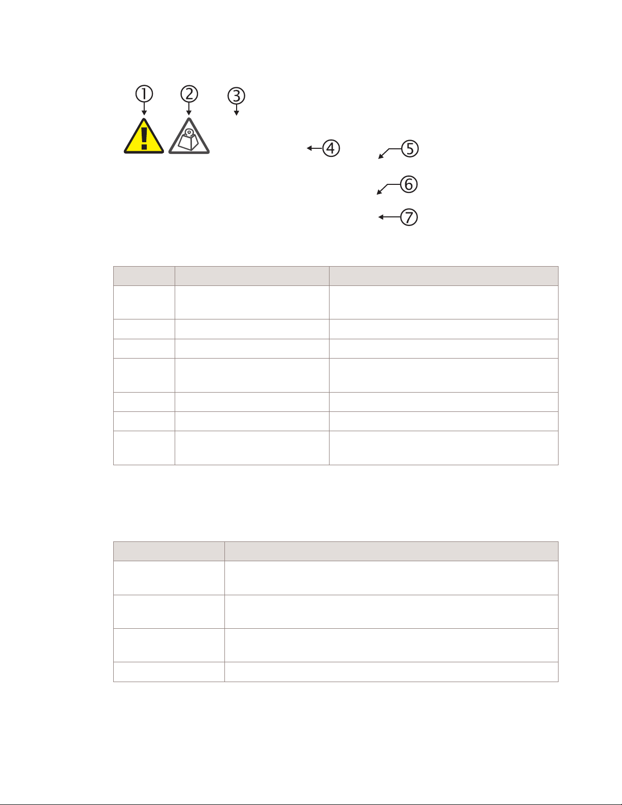
CAUTION
Lifting hazard
Lifting this equipment by yourself can result in injury
due to the size and weight of the equipment.
Always use three people or a lifting device to transport
SAMPLE
and position this equipment. [ABC123]
Item Structure element Purpose
1 Safety alert symbol Indicates the potential for personal injury
(optional)
2 Safety symbol Indicates hazard type (optional)
Signal words
3 Signal word Indicates the severity of the hazard
4 Hazard type Describes the source of the risk of damage or
injury
5 Safety message Consequences if protective measures fail
6 Avoidance message Protective measures to take to avoid the hazard
7 Identifier The reference ID of the safety statement
(optional)
The signal words identify the hazard severity levels as follows:
Signal word Meaning
DANGER Indicates an extremely hazardous situation which, if not avoided, will
result in death or serious injury.
WARNING Indicates a hazardous situation which, if not avoided, could result in
death or serious injury.
CAUTION Indicates a hazardous situation which, if not avoided, could result in
minor or moderate injury.
NOTICE Indicates a hazardous situation not related to personal injury.
....................................................................................................................................................................................................................................
1-2
RAFT
D
Alcatel-Lucent 9962 MSEC v1.0
3MN-02001-0002-RJZZA LR14 SCM
Issue 0.02 January 2015
Page 13
Safety and general information General hazard statements
....................................................................................................................................................................................................................................
General hazard statements
Purpose
Provides information on general hazard statements that may arise in the course of your
work, but are not necessarily related to a specific procedure.
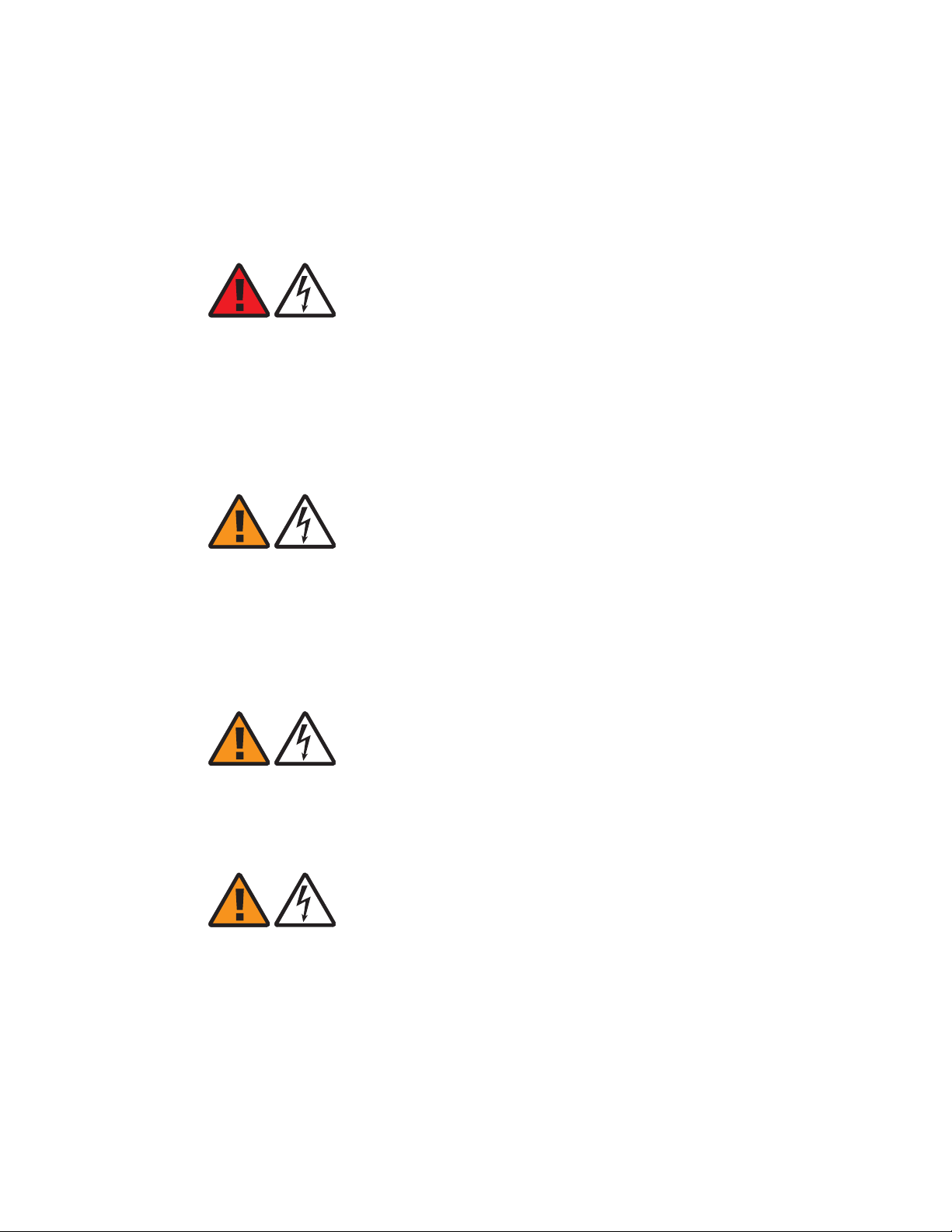
DANGER
Electric-shock hazard
This equipment generates high leakage current. This can lead to high voltages with
respect to ground for accessible parts of the installation. Contact with these parts can
cause serious health effects, possibly including death, even hours after the event.
This equipment is only suited for permanent connection. Before connecting the power
supply, establish a grounding connection.
D
RAFT
WARNING
Electric-shock hazard
Contact with energized parts can cause serious injury.
At least one other trained person must be in attendance, who can immediately and safely
disconnect the system if necessary.
This second person must be trained in first aid for emergency purposes.
WARNING
Electric-shock hazard
There is a danger of electric shock if the grounding system is inadequate.
You must comply with the grounding requirements for the grounding system.
WARNING
Electric-shock hazard
Contact with energized parts can cause serious injury.
Work on energized equipment is only permitted if you are using insulated connection
terminals, are adequately trained and follow safe work practices.
....................................................................................................................................................................................................................................
Alcatel-Lucent 9962 MSEC v1.0
3MN-02001-0002-RJZZA LR14 SCM
Issue 0.02 January 2015
1-3
D
RAFT
Page 14
Safety and general information General hazard statements
....................................................................................................................................................................................................................................
RAFT
WARNING
D
Electric-shock hazard
Contact with energized parts can cause serious personal injury.
Seal off the installation area (warning tape, signs) to prevent untrained or unauthorized
persons from entering.
Follow safe work practices and lockout/tagout procedures.
WARNING
Electric-shock hazard
Some parts of all electrical installations are energized. Failure to follow safe work
practices and the safety warnings may lead to bodily injury and property damage.
For this reason, only trained and qualified personnel (electrical workers as defined in
IEC 60215 or EN 60215 + A1 or in the National Electrical Code or in ANSI/NFPA No.
10) may install or service the installation.
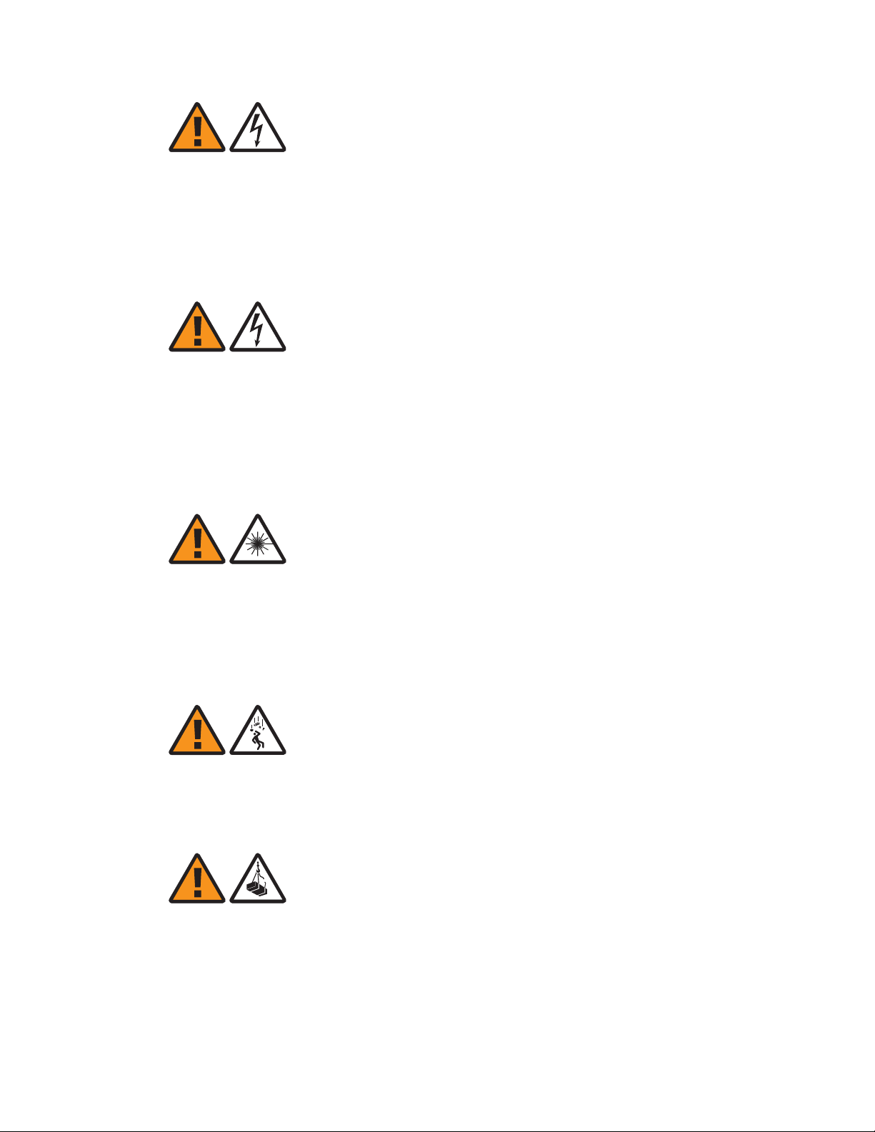
WARNING
Laser hazard
The light from laser and high-radiance LED’s may cause eye damage if absorbed by the
retina.
In the US consult ANSI Z136.2, in Europe consult IEC-60825 Safety of laser products, for
guidance on the safe use of optical fiber communication systems in the workplace.
WARNING
Falling-object hazard
Cabinet may tip when it is moved if an obstacle or a downward step is encountered.
Do not use dolly wheels if the installation location has an uneven surface, steps etc.
WARNING
Overhead-load hazard
Cabinet eyebolts can break, severely damaging the cabinet, if a crane is used to lift the
cabinet into an upright position.
Ensure that the cabinet is in an upright position before transportation by crane.
....................................................................................................................................................................................................................................
1-4
RAFT
D
Alcatel-Lucent 9962 MSEC v1.0
3MN-02001-0002-RJZZA LR14 SCM
Issue 0.02 January 2015
Page 15
Safety and general information General hazard statements
....................................................................................................................................................................................................................................
WARNING
Inhalation hazard
Inhalation of asbestos fibers can result in serious illness or death.
Buildings constructed before 1980 MAY contain asbestos. Buildings constructed before
1970 OFTEN contain asbestos. Potential exposure could occur during routing of cable or
wires, removing cables, removing transite or asbestos cement boards, drilling wallboard,
transite panels, or floor tiles, removing sprayed-on fireproofing, moving or removing
ceiling tiles, installing cable hangers.
Do not disturb asbestos. If asbestos is present, ensure potential expose is controlled by
adhering to local asbestos management regulations and follow safe work practices.
NOTICE
Service-disruption hazard
D
RAFT
Condensation can occur in the network element during transport, especially on moving
from outside to closed rooms. Condensation can cause malfunctioning of the circuit
packs.
Ensure that circuit packs and shelves have reached room temperature and are dry before
taking them into operation.
NOTICE
Service-disruption hazard
Tools left in the work area can cause short circuits during operation which can lead to the
destruction of units.
Make sure after finishing your work that no tools, testing equipment, flashlights, etc.,
have been left in or on the equipment.
CAUTION
Lifting hazard
Lifting this equipment by yourself can result in injury due to the size and weight of the
equipment.
Always use three people or a lifting device to transport and position this equipment.
....................................................................................................................................................................................................................................
Alcatel-Lucent 9962 MSEC v1.0
3MN-02001-0002-RJZZA LR14 SCM
Issue 0.02 January 2015
1-5
D
RAFT
Page 16
Safety and general information General hazard statements
....................................................................................................................................................................................................................................
RAFT
NOTICE
D
Flammable-material hazard
The heat vent (grill) at the top of the cabinet can become obstructed, preventing
ventilation of the cabinet.
Make sure that the airvent is not obstructed and remains clear at all times.
NOTICE
ESD hazard
Semiconductor components can be damaged by static discharges.
The following rules must be followed when handling any module containing
semiconductor components:
• Wear conductive or antistatic working clothes (for example, a coat made of 100%
cotton).
• Wear the grounded wrist strap.
• Wear shoes with conductive soles on a conductive floor surface or conductive work
mat.
• Leave the modules in their original packaging until ready for use.
• Make sure there is no difference in potential between yourself, the workplace, and the
packaging before removing, unpacking, or packing a module.
• Hold the module only by the grip without touching the connection pins, tracks, or
components.
• Place modules removed from the equipment on a conductive surface.
• Test or handle the module only with grounded tools on grounded equipment.
• Handle defective modules exactly like new ones to avoid causing further damage.
....................................................................................................................................................................................................................................
1-6
RAFT
D
Alcatel-Lucent 9962 MSEC v1.0
3MN-02001-0002-RJZZA LR14 SCM
Issue 0.02 January 2015
Page 17

Safety and general information Basic safety aspects
....................................................................................................................................................................................................................................
Basic safety aspects
General safety requirements
In order to keep the technically unavoidable residual risk to a minimum, it is imperative
to observe the following rules:
• DO NOT CONNECT CABLES TO WORKING/LIVE EQUIPMENT. This
activity should only be performed by the services/delivery team during
integration.
• Transport, storage, installation, and operation of the system must be under specified
permissible conditions only. See accompanying documentation and information on the
system.
• Installation, configuration, and disassembly must be carried out only by suitably
qualified personnel and with reference to the respective documentation. Due to the
complexity of the system, personnel require special training.
• Identify potential hazards prior to starting the installation.
• The system must be operated by trained and authorized users only. The user must only
operate the system after having read and understood the chapter on safety and the
parts of the documentation relevant to operation. For complex systems, additional
training is recommended. Any obligatory training for operating and service personnel
must be carried out and documented.
D
RAFT
• Follow all instructions marked on the product, including both general instructions and
the stated methods for avoiding hazards.
• The system must not be operated unless safety is guaranteed. Any faults and errors
that might affect safety must be reported immediately by the user to a person in
responsibility.
• The system must only be operated under the environmental conditions and with the
connections, described in the documentation.
• Modifications to any part of the system (including software) must be carried out by
Alcatel-Lucent or by trained and qualified personnel authorized by Alcatel-Lucent.
Unauthorized modifications will lead to a complete exemption from liability. Only
components recommended by the manufacturer and listed in the procurement
documents should be used.
• The use of non-system software is not recommended. The use/installation of
non-system software can adversely affect the normal functioning of the system.
• Only use tested and virus-free data carriers (for example, floppy disks and streamer
tapes).
• The removal or disabling of safety facilities, fault clearance, and maintenance of
equipment must be carried out by trained and qualified personnel only and in
conjunction with the respective documentation. Only approved measuring and test
equipment must be used.
D
....................................................................................................................................................................................................................................
Alcatel-Lucent 9962 MSEC v1.0
3MN-02001-0002-RJZZA LR14 SCM
Issue 0.02 January 2015
1-7
RAFT
Page 18

Safety and general information Basic safety aspects
....................................................................................................................................................................................................................................
RAFT
• Calibrations, special tests after repairs, and regular safety checks must be carried out,
documented, and archived.
D
• Follow applicable hazardous waste, electronic scrap, and take-back disposal
procedures.
Other important safety instructions
Observe the following safety instructions, they are of particular importance for your
safety:
• Be familiar with evacuation plans and emergency telephone numbers.
• Ensure first-aid kits are available.
• Wear appropriate personal protective equipment (PPE) such as safety glasses, hard
hats, gloves, and fall protection.
• Never wear jewelry (rings, bracelets, watches, etc.) when working on or near
energized equipment.
Summary of equipment safety instructions
Observe the following safety instructions while working with the equipment:
• This product is to be installed only in restricted access areas.
• This product should be only operated from the type of power source indicated on the
marking label.
• This product must be provided with a readily accessible disconnect device as part of
the building installation.
• Installation must include an independent frame ground drop to the building ground.
Refer to the Hardware Installation Guide.
• For information on correct mounting instruction, refer to the Hardware Installation
Guide.
• Install only equipment identified in the Hardware Installation Guide provided with
this product. Use of other equipment may result in improper connection of circuitry
leading to fire or injury to persons.
• To reduce the risk of electrical shock, do not disassemble this product. Only trained
personnel should install and service this product. Opening or removing covers and/or
circuit boards may expose you to dangerous voltages or other risks. Incorrect
reassembly can cause electrical shock when the unit is subsequently used.
• Slots and openings in this product are provided for ventilation. To protect the product
from overheating, these openings must not be blocked or covered. This product
should not be placed in a built-in installation unless proper ventilation is provided
....................................................................................................................................................................................................................................
1-8
RAFT
D
Alcatel-Lucent 9962 MSEC v1.0
3MN-02001-0002-RJZZA LR14 SCM
Issue 0.02 January 2015
Page 19

Safety and general information Basic safety aspects
....................................................................................................................................................................................................................................
• Never push objects of any kind into this product through slots as they may touch
dangerous voltage points or short-out parts that could result in risk of fire or electrical
shock. Never spill liquids of any kind on the product. Any telecommunication
interfaces should not leave the building premises unless connected to
telecommunication devices providing primary and secondary protection, as
applicable.
• Use caution when installing or modifying telecommunication lines.
• Never install telecommunication wiring during a lightning storm.
• Never install telecommunication connections in wet locations.
• Never touch non insulated telecommunication wires or terminals unless the
telecommunication line has been disconnected at the interface.
D
RAFT
....................................................................................................................................................................................................................................
Alcatel-Lucent 9962 MSEC v1.0
3MN-02001-0002-RJZZA LR14 SCM
Issue 0.02 January 2015
1-9
D
RAFT
Page 20

Safety and general information Basic safety aspects
....................................................................................................................................................................................................................................
RAFT
D
....................................................................................................................................................................................................................................
1-10
RAFT
D
Alcatel-Lucent 9962 MSEC v1.0
3MN-02001-0002-RJZZA LR14 SCM
Issue 0.02 January 2015
Page 21

2 2Alcatel-Lucent 9962
Multi-standard Enterprise
Cell v1 installation
Overview
Purpose
This chapter describes the installation procedure for the 9962 MSEC v1.0 access point.
Contents
D
RAFT
Pre-installation information 2-1
Mounting guidelines 2-4
Cabling 2-10
Pre-installation information
Introduction
The Alcatel-Lucent 9962 Multi-standard Enterprise Cell v1, or 9962 MSEC v1.0, is a
wireless access point using licensed spectrum delivering improved network reach and
increased capacity while offloading traffic from the macro network.
The 9962 MSEC v1.0 supports simultaneous transmission of three different air interface
technologies:
• LTE
• WCDMA
• WiFi
As part of the Alcatel-Lucent 9360 Small Cell Solution, it can be deployed in a network
supporting a mix of Home and Enterprise cells.
Refer to the Alcatel-Lucent 9962 Multi-standard Enterprise Cell v1 - Technical
Description, 3MN-02001-0003-DEZZA for complete technical details on the 9962 MSEC
v1.0 access point.
...................................................................................................................................................................................................................................
Alcatel-Lucent 9962 MSEC v1.0
3MN-02001-0002-RJZZA LR14 SCM
Issue 0.02 January 2015
2-1
D
RAFT
Page 22

Alcatel-Lucent 9962 Multi-standard Enterprise Cell v1
installation
....................................................................................................................................................................................................................................
Device placement
RAFT
D
The Alcatel-Lucent 9962 Multi-standard Enterprise Cell v1 has been designed to be
Pre-installation information
deployed in any (and only) indoor environment :
• either in private places such as business offices, warehouses etc,
• either in public places such as supermarkets, shopping malls, airports etc.
The access point and all its components (including cables and power adaptor) have to be
placed in a dry area and be kept away from any wet or damp environments; such as
lavatories or any other areas with exposure to moisture, sprays, drips, or running water.
For the safety of stored data, it must not be placed near magnetic devices such as audio or
video tapes.
The 9962 MSEC v1.0 emits a radio signal. The quality of coverage achieved therefore
depends upon where the device is placed.
For best results it should be located:
• In a central place within the area in which the product is intended to operate,
• As high as possible, for example, on high shelving, or mounted on a wall.
To improve coverage, avoid installing near the following:
• Other radio transmitters
• Other metallic devices or objects
• Windows
Product delivery contents
The 9962 MSEC v1.0 is provided in a standard cardboard box. The contents are as
follows:
• The 9962 MSEC v1.0 access point
• A wall mounting kit
• A quick start guide/user guide
• A GPS antenna with 10m cable length
Ancillary items
In addition to the standard delivered parts the following ancillary items are available but
must be ordered separately if needed:
• SFP transceivers
• Data cables
• 4p PoE compliant with PoH standard adapter
• AC to DC power adapter
• Lock
....................................................................................................................................................................................................................................
2-2
RAFT
D
Alcatel-Lucent 9962 MSEC v1.0
3MN-02001-0002-RJZZA LR14 SCM
Issue 0.02 January 2015
Page 23

Alcatel-Lucent 9962 Multi-standard Enterprise Cell v1
installation
....................................................................................................................................................................................................................................
Pre-installation information
• Wall mount stick antenna
• Jumper type N to SMA cables
Installation tools required
The following is a list of the tools that may be used during installation:
• Drill and assorted drill bits
• Screwdrivers (power and/or manual)
• Measuring tape
• Marker, to mark wall mounting holes
• Vacuum cleaner or equivalent (required for clearing debris from wall mounting holes)
• Spirit level
D
RAFT
....................................................................................................................................................................................................................................
Alcatel-Lucent 9962 MSEC v1.0
3MN-02001-0002-RJZZA LR14 SCM
Issue 0.02 January 2015
2-3
D
RAFT
Page 24

Alcatel-Lucent 9962 Multi-standard Enterprise Cell v1
installation
....................................................................................................................................................................................................................................
RAFT
Mounting guidelines
Mounting guidelines
D
Introduction
The 9962 MSEC v1.0 has been designed for an effective plug & play installation. The
device is based on single hardware core associated with dedicated wall mounting kit.
This topic describes the procedures to be followed when installing the 9962 MSEC v1.0
access point.
Prerequisites
A site survey has been conducted and a location for the device has been selected that is
both central to the available space and elevated in order to maximize coverage.
Before installation begins you should ensure the following are in place:
• Internet service is available,
• The Ethernet cable has been routed and is in place,
• Site specific fixing materials according to the mounting (wall or ceiling).
Mounting characteristics
Radiated patterns of integrated and attached 9962 MSEC v1.0 antennas are optimized for
wall mounting installation.
....................................................................................................................................................................................................................................
2-4
RAFT
D
Alcatel-Lucent 9962 MSEC v1.0
3MN-02001-0002-RJZZA LR14 SCM
Issue 0.02 January 2015
Page 25

Alcatel-Lucent 9962 Multi-standard Enterprise Cell v1
installation
....................................................................................................................................................................................................................................
Figure 2-1 9962 MSEC v1.0 antenna
Mounting guidelines
D
RAFT
Attention: The access point is only supported in the upright orientation with the
external antennas pointing upward (not downwards or sideways). The external
antennas cannot be flipped. Failure to comply with these requirements would
change and degrade the omnidirectional radio frequency pattern.
The wall mounting installation is easy and fast: it takes benefit of the small footprint of
the 9962 MSEC v1.0 access point by offering a small visible size and making it
inconspicuous.
Important! Various building materials and construction methods dictate that the
device be fastened to the wall with appropriate mounting hardware. It is the
responsibility of the customer to provide any necessary support material and
structures to ensure that the installation will be in compliance with Building Officials
and Code Administrators (BOCA), Uniform Building Code (UBC), and all local
codes.
....................................................................................................................................................................................................................................
Alcatel-Lucent 9962 MSEC v1.0
3MN-02001-0002-RJZZA LR14 SCM
Issue 0.02 January 2015
2-5
D
RAFT
Page 26

Alcatel-Lucent 9962 Multi-standard Enterprise Cell v1
installation
....................................................................................................................................................................................................................................
Mounting plate
RAFT
D
The 9962 MSEC v1.0 requires a mounting plate to be installed onto the wall.
Mounting guidelines
The following figure illustrates the mounting plate.
Figure 2-2 9962 MSEC v1.0 mounting plate
Before you begin
Note: Record the 18 digit serial number before mounting the 9962 MSEC v1.0 access
point.
Mount to wall
WARNING
Fall hazard
Falls can occur when working at heights resulting in serious personal injury or death.
To prevent a fall when working at heights (ladder, scaffold, manlift, roof etc.) follow safe
work practices and wear appropriate fall protection equipment.
....................................................................................................................................................................................................................................
2-6
RAFT
D
Alcatel-Lucent 9962 MSEC v1.0
3MN-02001-0002-RJZZA LR14 SCM
Issue 0.02 January 2015
Page 27

Alcatel-Lucent 9962 Multi-standard Enterprise Cell v1
installation
....................................................................................................................................................................................................................................
Mounting guidelines
To mount the device onto a wall, perform the following steps:
...................................................................................................................................................................................................
At the selected installation location, mark the points on the flat surface for the four (4)
1
fixing holes, using the holes in the mounting plate as a guide.
Check the horizontal position with a spirit level.
...................................................................................................................................................................................................
Drill holes at the marked points, and insert wall plugs into the fixing holes.
2
...................................................................................................................................................................................................
Attach the mounting plate to the wall using appropriate screw fixings.
3
Note: Depending on the wall the device must be mounted to, different screw fixings
might be needed. After site survey, these mounting accessories must be procured
locally.
...................................................................................................................................................................................................
D
RAFT
Connect the cables.
4
...................................................................................................................................................................................................
Attach the 9962 MSEC v1.0 to the mounting plate as follows:
5
1. Line up the four grooves in the back of the 9962 MSEC v1.0 with the four notches
protruding from the mounting plate.
The following graphic shows the notches and the lock location on the mounting plate and
the grooves in the back of the 9962 MSEC v1.0:
....................................................................................................................................................................................................................................
Alcatel-Lucent 9962 MSEC v1.0
3MN-02001-0002-RJZZA LR14 SCM
Issue 0.02 January 2015
2-7
D
RAFT
Page 28

Alcatel-Lucent 9962 Multi-standard Enterprise Cell v1
installation
....................................................................................................................................................................................................................................
Mounting guidelines
RAFT
D
Figure 2-3 Notch, groove and lock locations
2. Push the 9962 MSEC v1.0 downwards to lock it into position.
3. Then screw four (4) screws to attach the 9962 MSEC v1.0 to the mounting plate.
...................................................................................................................................................................................................
If locks have been ordered by the customer, attach the lock to secure the 9962 MSEC v1.0
6
from removing of the mounting plate.
The following graphic shows the mounting plate attached to the back of the 9962 MSEC
v1.0:
....................................................................................................................................................................................................................................
2-8
RAFT
D
Alcatel-Lucent 9962 MSEC v1.0
3MN-02001-0002-RJZZA LR14 SCM
Issue 0.02 January 2015
Page 29

Alcatel-Lucent 9962 Multi-standard Enterprise Cell v1
installation
....................................................................................................................................................................................................................................
Mounting guidelines
Figure 2-4 Mounting plate on the 9962 MSEC v1.0 access point
D
RAFT
E ND OF STEPS
...................................................................................................................................................................................................
....................................................................................................................................................................................................................................
Alcatel-Lucent 9962 MSEC v1.0
3MN-02001-0002-RJZZA LR14 SCM
Issue 0.02 January 2015
2-9
D
RAFT
Page 30

Alcatel-Lucent 9962 Multi-standard Enterprise Cell v1
installation
....................................................................................................................................................................................................................................
RAFT
Cabling
Cabling
D
Purpose
This topic describes the procedures to be followed when connecting the 9962 MSEC v1.0
cables.
Cable connectors
The following picture shows the positions of the different physical connectors and
antennas on the 9962 MSEC v1.0 access point:
Figure 2-5 9962 MSEC v1.0 connectors and antennas
The 9962 MSEC v1.0 access point provides two GE ports for backhaul and daisy chain
(refer to
“Daisy chain” (p. 2-13) for details about the daisy chaining).
One of those ports provides a RJ45 connector and the second port a SFP slot.
If the SFP port is already used, it is possible to use the RJ45 port with an adapted SFP.
....................................................................................................................................................................................................................................
2-10
RAFT
D
Alcatel-Lucent 9962 MSEC v1.0
3MN-02001-0002-RJZZA LR14 SCM
Issue 0.02 January 2015
Page 31

Alcatel-Lucent 9962 Multi-standard Enterprise Cell v1
installation
....................................................................................................................................................................................................................................
Cabling
Power supply and backhaul options
The 9962 MSEC v1.0 access point can be powered through:
• DC input power with an AC-DC power adapter including an appropriate Jack,
• or 4p PoE compliant with PoH standard (following IEEE 802.3 at Power over
Ethernet standard).
If PoE compliant with PoH standard is used to supply the power then a PoE injector
or a PoE capable router can be used.
Data cables
Each 9962 MSEC v1.0 access point requires at least one data cable to connect the
backhaul. In case of daisy chain, an additional data cable is required (refer to
chain” (p. 2-13)
).
“Daisy
The data cable can be a standard Ethernet cable with RJ45 connector or a fiber cable with
an optical transceiver.
Before you begin
D
RAFT
Ensure the 9962 MSEC v1.0 access point has been correctly installed.
Connect the 9962 MSEC v1.0 cables
...................................................................................................................................................................................................
According to the configuration on site, select the appropriate option in the following
1
table, and perform the associated procedure:
If you want to... Then ...
Use an AC-DC power adaptor and a standard
router,
Use PoE supplied by a DSL router with PoE
function,
E ND OF STEPS
...................................................................................................................................................................................................
Connect to a standard DSL router
Go to
“Connect to a standard DSL router”
(p. 2-11)
and “Connect the AC-DC power
adapter” (p. 2-12)
Go to “Connect to a DSL router with PoE
function” (p. 2-12)
To connect the 9962 MSEC v1.0 to a standard DSL router using an Ethernet cable
through which power is not supplied, perform the following steps:
...................................................................................................................................................................................................
Route the Ethernet cable from the 9962 MSEC v1.0 to a standard DSL router.
1
....................................................................................................................................................................................................................................
Alcatel-Lucent 9962 MSEC v1.0
3MN-02001-0002-RJZZA LR14 SCM
Issue 0.02 January 2015
2-11
D
RAFT
Page 32

Alcatel-Lucent 9962 Multi-standard Enterprise Cell v1
installation
....................................................................................................................................................................................................................................
RAFT
D
...................................................................................................................................................................................................
Connect one end of the Ethernet cable to the 9962 MSEC v1.0.
2
...................................................................................................................................................................................................
Connect the other end of the Ethernet cable to the router.
3
...................................................................................................................................................................................................
Finally, secure the Ethernet cable to the wall.
4
E ND OF STEPS
...................................................................................................................................................................................................
Cabling
Connect the AC-DC power adapter
If you intend to use an AC-DC power adapter to supply power to the 9962 MSEC v1.0,
perform the following steps:
...................................................................................................................................................................................................
Route the power supply cable from the 9962 MSEC v1.0 to the supplied AC-DC power
1
adapter.
...................................................................................................................................................................................................
Connect the power supply cable to the 9962 MSEC v1.0.
2
...................................................................................................................................................................................................
Finally, secure the power supply cable to the wall.
3
E ND OF STEPS
...................................................................................................................................................................................................
Connect to a DSL router with PoE function
To connect the 9962 MSEC v1.0 to a DSL router with PoE function, perform the
following steps:
...................................................................................................................................................................................................
Route the Ethernet cable from the 9962 MSEC v1.0 to a DSL router with PoE function.
1
...................................................................................................................................................................................................
Connect one end of the Ethernet cable to the 9962 MSEC v1.0.
2
...................................................................................................................................................................................................
Connect the other end of Ethernet cable to the router.
3
....................................................................................................................................................................................................................................
2-12
RAFT
D
Alcatel-Lucent 9962 MSEC v1.0
3MN-02001-0002-RJZZA LR14 SCM
Issue 0.02 January 2015
Page 33

Alcatel-Lucent 9962 Multi-standard Enterprise Cell v1
installation
....................................................................................................................................................................................................................................
...................................................................................................................................................................................................
Finally, secure the Ethernet cable to the wall.
4
E ND OF STEPS
...................................................................................................................................................................................................
Cabling
Connect to the GPS antenna
The GPS antenna is used for synchronization purpose. Perform the following steps to
connect the 9962 MSEC v1.0 to the GPS antenna:
...................................................................................................................................................................................................
Route the GPS antenna cable to the 9962 MSEC v1.0 access point.
1
...................................................................................................................................................................................................
Connect the GPS antenna cable to the dedicated SMA connector in the 9962 MSEC v1.0.
2
...................................................................................................................................................................................................
D
RAFT
3
Daisy chain
Finally, secure the GPS antenna cable to the wall.
E ND OF STEPS
...................................................................................................................................................................................................
The 9962 MSEC v1.0 access point can be linked in a daisy chain with up to eight devices.
The daisy chain hop is set by connecting the SFP slot of the “Master” access point to the
RJ45 port of the “Slave” access point. Therefore, the “Master” SFP slot must be equipped
with an appropriate RJ45 SFP .
....................................................................................................................................................................................................................................
Alcatel-Lucent 9962 MSEC v1.0
3MN-02001-0002-RJZZA LR14 SCM
Issue 0.02 January 2015
2-13
D
RAFT
Page 34

Alcatel-Lucent 9962 Multi-standard Enterprise Cell v1
installation
....................................................................................................................................................................................................................................
Cabling
RAFT
D
Figure 2-6 Example of 4 9962 MSEC v1.0 daisy chain
....................................................................................................................................................................................................................................
2-14
RAFT
D
Alcatel-Lucent 9962 MSEC v1.0
3MN-02001-0002-RJZZA LR14 SCM
Issue 0.02 January 2015
Page 35

3 3Alcatel-Lucent 9962
Multi-standard Enterprise
Cell v1 commissioning
Overview
Purpose
This chapter describes the 9962 MSEC v1.0 commissioning process. The 9962 MSEC
v1.0 is self commissioning in the case of single device deployments.
D
RAFT
Contents
Commissioning process 3-2
...................................................................................................................................................................................................................................
Alcatel-Lucent 9962 MSEC v1.0
3MN-02001-0002-RJZZA LR14 SCM
Issue 0.02 January 2015
3-1
D
RAFT
Page 36

Alcatel-Lucent 9962 Multi-standard Enterprise Cell v1
commissioning
....................................................................................................................................................................................................................................
RAFT
Commissioning process
Commissioning process
D
Overview
The 9962 MSEC v1.0 supports the following technology combinations:
• One cell of LTE,
• One cell of WCDMA,
• One cell of LTE plus one cell of WCDMA.
In any of these configurations the 9962 MSEC v1.0 simultaneously supports WiFi thanks
to the integrated Motorola WiFi module that supports 802.11n operation.
GPS is the primary frequency reference source and is used whenever satellite signal is
available, fallback is to NTP.
Purpose
This section outlines the 9962 MSEC v1.0 zero-touch commissioning process.
Related information
If any problems occur during the commissioning process refer to the following document
for more details:
• Alcatel-Lucent 9962 Multi-standard Enterprise Cell v1 - Technical Description,
3MN-02001-0003-DEZZA
Before you begin
The 9962 MSEC v1.0 is intended to be installed and then left unattended so the LED
pattern activated in the commissioning process is mainly focused on indicating that the
installation and initial network connection have succeeded and that the access point is
properly functioning.
9962 MSEC v1.0 access point commissioning
...................................................................................................................................................................................................
Power on the 9962 MSEC v1.0 access point. All LEDs (Power, LTE, WCDMA and GPS)
1
are solid red: if the software fails to start, the LEDs remain in this condition. Otherwise
the LEDs indicate the progress of the initialization of the unit.
....................................................................................................................................................................................................................................
3-2
RAFT
D
Alcatel-Lucent 9962 MSEC v1.0
3MN-02001-0002-RJZZA LR14 SCM
Issue 0.02 January 2015
Page 37

Alcatel-Lucent 9962 Multi-standard Enterprise Cell v1
commissioning
....................................................................................................................................................................................................................................
Commissioning process
Figure 3-1 9962 MSEC v1.0 front LEDs
...................................................................................................................................................................................................
D
RAFT
After approximately 2 minutes the 9962 MSEC v1.0 access point will initialize and
2
establish IPsec connectivity. During this operation the Power status indicator will blink
slowly. Only red at the beginning then toggling red/green once the access point attempts
to contact DNS Internal for HDM/SAM address resolution.
...................................................................................................................................................................................................
After the 9962 MSEC v1.0 access point has established a network connection it will
3
automatically update its software and configuration database. This process takes
approximately 15 minutes. During this operation the Power indicator will blink green.
...................................................................................................................................................................................................
Once the software update has completed the 9962 MSEC v1.0 access point will carry out
4
an automatic reboot. During reboot the Power indicator will still be blinking green.
...................................................................................................................................................................................................
The access point is ready to enable applications and the Power indicator is solid green.
5
...................................................................................................................................................................................................
The 9962 MSEC v1.0 access point starts looking for a GPS signal: the GPS LED is
6
blinking red.
Important! If GPS signal is not available, the GPS LED turns off.
...................................................................................................................................................................................................
A soon as the GPS signal is acquired, the GPS LED goes solid green.
7
....................................................................................................................................................................................................................................
Alcatel-Lucent 9962 MSEC v1.0
3MN-02001-0002-RJZZA LR14 SCM
Issue 0.02 January 2015
3-3
D
RAFT
Page 38

Alcatel-Lucent 9962 Multi-standard Enterprise Cell v1
commissioning
....................................................................................................................................................................................................................................
RAFT
D
...................................................................................................................................................................................................
8
If the access point configuration ... Then ...
supports one LTE cell go to
“LTE commissioning” (p. 3-4)
Commissioning process
supports one WCDMA cell go to “WCDMA commissioning” (p. 3-4)
supports WiFi go to “WiFi commissioning” (p. 3-5)
...................................................................................................................................................................................................
After the 9962 MSEC v1.0 access point has been in a normal system state for fifteen
9
minutes, all the non-WiFi LEDs are turned off to avoid bringing attention to the unit.
They remain off until one of them changes to an Off-Normal state. As the WiFi LEDs are
managed by the WiFi module they are not included in this procedure but turned off in a
separate procedure after thirty minutes in the same state.
E ND OF STEPS
...................................................................................................................................................................................................
LTE commissioning
...................................................................................................................................................................................................
The 9962 MSEC v1.0 access point starts its LTE auto-configuration and self optimisation
1
of the radio access. During this operation the LTE status indicator will blink red/green
until the service is operational marked by a solid green LTE status indicator.
Important! In case the configuration supports only one LTE cell, the WCDMA LED
is off. If the configuration enables LTE and WCDMA concurrent operation, the LTE
and WCDMA commissioning proceed simultaneously.
...................................................................................................................................................................................................
Return to the Step 8.
2
E ND OF STEPS
...................................................................................................................................................................................................
WCDMA commissioning
...................................................................................................................................................................................................
The 9962 MSEC v1.0 access point starts its WCDMA auto-configuration and self
1
optimisation of the radio access. During this operation the WCDMA status indicator will
blink red/green until the WCDMA service is operational marked by a solid green
WCDMA status indicator.
....................................................................................................................................................................................................................................
3-4
RAFT
D
Alcatel-Lucent 9962 MSEC v1.0
3MN-02001-0002-RJZZA LR14 SCM
Issue 0.02 January 2015
Page 39

Alcatel-Lucent 9962 Multi-standard Enterprise Cell v1
commissioning
....................................................................................................................................................................................................................................
Commissioning process
Important! In case the configuration supports only one WCDMA cell, the LTE LED
is off. If the configuration enables WCDMA and LTE concurrent operation, the
WCDMA and LTE commissioning proceed simultaneously.
...................................................................................................................................................................................................
Return to the Step 8.
2
E ND OF STEPS
...................................................................................................................................................................................................
WiFi commissioning
The 9962 MSEC v1.0 integrated WiFi module manages the WiFi LEDs located at the rear
of the access point.
...................................................................................................................................................................................................
As soon as the access point is powered on, the 9962 MSEC v1.0 starts booting and the
1
WiFi LEDs are solid on.
D
RAFT
Figure 3-2 9962 MSEC v1.0 WiFi LEDs
...................................................................................................................................................................................................
Then the 9962 MSEC v1.0 tries to get adopted by the controller and the 5GHz LED starts
2
blinking slowly. The 2GHz LED related to the 2.4GHz frequency is off.
...................................................................................................................................................................................................
The controller pushes the configuration. During this operation the both WiFi LEDs will
3
blink quickly until the service is operational marked by a slow blinking WiFi status
indicator.
The WiFi service may be operational on a single frequency (2.4GHz or 5GHz) or
simultaneously on the both frequencies.
....................................................................................................................................................................................................................................
Alcatel-Lucent 9962 MSEC v1.0
3MN-02001-0002-RJZZA LR14 SCM
Issue 0.02 January 2015
3-5
D
RAFT
Page 40

Alcatel-Lucent 9962 Multi-standard Enterprise Cell v1
commissioning
....................................................................................................................................................................................................................................
RAFT
D
...................................................................................................................................................................................................
Return to the Step 9.
4
E ND OF STEPS
...................................................................................................................................................................................................
Commissioning process
....................................................................................................................................................................................................................................
3-6
RAFT
D
Alcatel-Lucent 9962 MSEC v1.0
3MN-02001-0002-RJZZA LR14 SCM
Issue 0.02 January 2015
Page 41

4 4Post-installation activities
Overview
Purpose
This chapter describes the post-installation activities and checks.
Contents
D
RAFT
Post-installation information 4-2
...................................................................................................................................................................................................................................
Alcatel-Lucent 9962 MSEC v1.0
3MN-02001-0002-RJZZA LR14 SCM
Issue 0.02 January 2015
4-1
D
RAFT
Page 42

Post-installation activities Post-installation information
....................................................................................................................................................................................................................................
RAFT
Post-installation information
D
Final installation checks
Before leaving the installation site, carry out the following:
...................................................................................................................................................................................................
Secure all cables along their routes.
1
...................................................................................................................................................................................................
Verify that all the exterior conduit and cable connections are secure.
2
...................................................................................................................................................................................................
Inspect the site and remove all loose tools, materials, and parts.
3
E ND OF STEPS
...................................................................................................................................................................................................
....................................................................................................................................................................................................................................
4-2
RAFT
D
Alcatel-Lucent 9962 MSEC v1.0
3MN-02001-0002-RJZZA LR14 SCM
Issue 0.02 January 2015
Page 43

Appendix A: Product conformance statements
Overview
Purpose
This appendix provides the product conformance statements relating to the Alcatel-Lucent
9962 MSEC v1.0.
D
RAFT
Contents
United States A-1
Environmental requirements A-2
United States
Introduction
The statements that follow are the product conformance and eco-environmental
statements that apply to the 9962 MSEC v1.0 when deployed in the United States.
Federal Communications Commission
Important! Changes or modifications not expressly approved by Alcatel-Lucent, Inc.
could void the user's authority to operate the equipment.
This device complies with Part 15 of the FCC Rules. Operation is subject to the following
two conditions:
• This device may not cause harmful interference
• This device must accept any interference received, including interference that may
cause undesired operation.
...................................................................................................................................................................................................................................
Alcatel-Lucent 9962 MSEC v1.0
3MN-02001-0002-RJZZA LR14 SCM
Issue 0.02 January 2015
A-1
D
RAFT
Page 44

Product conformance statements United States
....................................................................................................................................................................................................................................
Packaging collection recovery requirements
RAFT
D
Countries, states, localities, or other jurisdictions may require that systems be established
for the return and/or collection of packaging waste from the consumer, or other end user,
or from the waste stream. Additionally, reuse, recovery, and/or recycling targets for the
return and/or collection of the packaging waste may be established.
For more information regarding collection and recovery of packaging and packaging
waste within specific jurisdictions, please contact the Alcatel-Lucent Field Services /
Installation - Environmental Health and Safety organization.
For technical support, contact your local Alcatel-Lucent customer support team. See the
Alcatel-Lucent Support web site http://www.alcatel-lucent.com/support/ for contact
information.
Environmental requirements
Environmental factors
The installation location requires the following environmental factors to be controlled:
• Temperature
• Humidity
• Ventilation
Environmental limits
The atmosphere in the room that houses the device must be maintained within the
following limits:
Environmental factor
Operating
temperature
Operating
relative
humidity
Requirement Range
Normal Operation -5°C to 50°C (23°F to 122°F)
• Telcordia GR-63-CORE
• Telcordia GR-3108-CORE
• ANSI ATIS-0600010.2007
Cold start-up
Condensing 5% to 90%
• Telcordia GR-63-CORE
• Telcordia GR-3108-CORE
• ANSI ATIS-0600010.2007
....................................................................................................................................................................................................................................
A-2
RAFT
D
Alcatel-Lucent 9962 MSEC v1.0
3MN-02001-0002-RJZZA LR14 SCM
Issue 0.02 January 2015
Page 45

Product conformance statements Environmental requirements
....................................................................................................................................................................................................................................
D
RAFT
Environmen-
Requirement Range
tal factor
Ingress protection NEMA Level 1
IP2X of IEC 60529
Operating
0 to 4000m (13 000ft)
altitude
Vibration NAR Telcordia GR-63-CORE sections
4.4.4 & 5.4.2
Earthquake Richter scale 7
....................................................................................................................................................................................................................................
Alcatel-Lucent 9962 MSEC v1.0
3MN-02001-0002-RJZZA LR14 SCM
Issue 0.02 January 2015
A-3
D
RAFT
Page 46

Product conformance statements Environmental requirements
....................................................................................................................................................................................................................................
RAFT
D
....................................................................................................................................................................................................................................
A-4
RAFT
D
Alcatel-Lucent 9962 MSEC v1.0
3MN-02001-0002-RJZZA LR14 SCM
Issue 0.02 January 2015
Page 47

D
Glossary
...................................................................................................................................................................................................................................
Numerics
4p PoE
4 pair Power over Ethernet
...................................................................................................................................................................................................................................
AAC
Alternative Current
...................................................................................................................................................................................................................................
DDC
Direct Current
DNS
Domain Name Server
RAFT
DSL
Digital Subscriber Line
...................................................................................................................................................................................................................................
EEU
European Union
...................................................................................................................................................................................................................................
GGE
Giga Ethernet
GPS
Global Positioning System
...................................................................................................................................................................................................................................
H HDM
Home Device Manager
...................................................................................................................................................................................................................................
IIP
Internet Protocol
....................................................................................................................................................................................................................................
Alcatel-Lucent 9962 MSEC v1.0
3MN-02001-0002-RJZZA LR14 SCM
Issue 0.02 January 2015
GL-1
D
RAFT
Page 48

Glossary
....................................................................................................................................................................................................................................
...................................................................................................................................................................................................................................
RAFT
LLTE
D
Long Term Evolution - 4G
...................................................................................................................................................................................................................................
N NAR
North America
NTP
Network Time Protocol
...................................................................................................................................................................................................................................
P PoE+
Power over Ethernet
PoH
Power-on Hours
...................................................................................................................................................................................................................................
R RNC
Radio Network Controller
...................................................................................................................................................................................................................................
S SAM
Service Activation Manager
SFP
Small form-factor pluggable
...................................................................................................................................................................................................................................
W WCDMA
Wideband Code Division Multiple Access
WiFi
Wireless Fidelity (IEEE 802.11b wireless networking)
....................................................................................................................................................................................................................................
GL-2
RAFT
D
Alcatel-Lucent 9962 MSEC v1.0
3MN-02001-0002-RJZZA LR14 SCM
Issue 0.02 January 2015
Page 49

D
Index
Numerics
9962 MSEC v1.0 installation, 2-1
.............................................................
Alcatel-Lucent 9962
A
Multi-standard Enterprise Cell v1
cabling,
commissioning, 3-2
mounting guidelines, 2-4
.............................................................
2-10
RAFT
document support, viii
D
.............................................................
environmental requirements, A-2
E
.............................................................
General hazard statements, 1-3
G
.............................................................
phone numbers
P
for document support,
Post-installation, 4-2
Pre-installation information, 2-1
viii
D
....................................................................................................................................................................................................................................
Alcatel-Lucent 9962 MSEC v1.0
3MN-02001-0002-RJZZA LR14 SCM
Issue 0.02 January 2015
IN-1
RAFT
Page 50

Index
....................................................................................................................................................................................................................................
RAFT
D
....................................................................................................................................................................................................................................
IN-2
RAFT
D
Alcatel-Lucent 9962 MSEC v1.0
3MN-02001-0002-RJZZA LR14 SCM
Issue 0.02 January 2015
Page 51

Federal Communication Commission Interference Statement
This device complies with Part 15 of the FCC Rules. Operation is subject to the following
two conditions: (1) This device may not cause harmful interference, and (2) this device
must accept any interference received, including interference that may cause undesired
operation.
This equipment has been tested and found to comply with the limits for a Class B digital
device, pursuant to Part 15 of the FCC Rules. These limits are designed to provide
reasonable protection against harmful interference in a residential installation. This
equipment generates, uses and can radiate radio frequency energy and, if not installed and
used in accordance with the instructions, may cause harmful interference to radio
communications. However, there is no guarantee that interference will not occur in a
particular installation. If this equipment does cause harmful interference to radio or
television reception, which can be determined by turning the equipment off and on, the
user is encouraged to try to correct the interference by one of the following measures:
-Reorient or relocate the receiving antenna.
-Increase the separation between the equipment and receiver.
-Connect the equipment into an outlet on a circuit different from that to which the receiver
is connected.
-Consult the dealer or an experienced radio/TV technician for help.
FCC Caution: Any changes or modifications not expressly approved by the party
responsible for compliance could void the user's authority to operate this equipment.
This transmitter must not be co-located or operating in conjunction with any other antenna
or transmitter.
Note: The country code selection is for non-US model only and is not available to all US
model. Per FCC regulation, all WiFi product marketed in US must fixed to US operation
channels only.
Operations in the 5.15-5.25GHz band are restricted to indoor usage only.
Radiation Exposure Statement:
This equipment complies with FCC radiation exposure limits set forth for an uncontrolled
environment. This equipment should be installed and operated with minimum distance
20cm between the radiator & your body.
 Loading...